CN111003099B - Bicycle shifter with high precision control and method of shifting gears in a bicycle shifter - Google Patents
Bicycle shifter with high precision control and method of shifting gears in a bicycle shifter Download PDFInfo
- Publication number
- CN111003099B CN111003099B CN201910931936.9A CN201910931936A CN111003099B CN 111003099 B CN111003099 B CN 111003099B CN 201910931936 A CN201910931936 A CN 201910931936A CN 111003099 B CN111003099 B CN 111003099B
- Authority
- CN
- China
- Prior art keywords
- pin
- sprocket
- shifter
- gear set
- bicycle shifter
- Prior art date
- Legal status (The legal status is an assumption and is not a legal conclusion. Google has not performed a legal analysis and makes no representation as to the accuracy of the status listed.)
- Active
Links
Images


Classifications
-
- B—PERFORMING OPERATIONS; TRANSPORTING
- B62—LAND VEHICLES FOR TRAVELLING OTHERWISE THAN ON RAILS
- B62M—RIDER PROPULSION OF WHEELED VEHICLES OR SLEDGES; POWERED PROPULSION OF SLEDGES OR SINGLE-TRACK CYCLES; TRANSMISSIONS SPECIALLY ADAPTED FOR SUCH VEHICLES
- B62M9/00—Transmissions characterised by use of an endless chain, belt, or the like
- B62M9/04—Transmissions characterised by use of an endless chain, belt, or the like of changeable ratio
- B62M9/06—Transmissions characterised by use of an endless chain, belt, or the like of changeable ratio using a single chain, belt, or the like
- B62M9/10—Transmissions characterised by use of an endless chain, belt, or the like of changeable ratio using a single chain, belt, or the like involving different-sized wheels, e.g. rear sprocket chain wheels selectively engaged by the chain, belt, or the like
- B62M9/12—Transmissions characterised by use of an endless chain, belt, or the like of changeable ratio using a single chain, belt, or the like involving different-sized wheels, e.g. rear sprocket chain wheels selectively engaged by the chain, belt, or the like the chain, belt, or the like being laterally shiftable, e.g. using a rear derailleur
- B62M9/121—Rear derailleurs
- B62M9/126—Chain guides; Mounting thereof
-
- B—PERFORMING OPERATIONS; TRANSPORTING
- B62—LAND VEHICLES FOR TRAVELLING OTHERWISE THAN ON RAILS
- B62M—RIDER PROPULSION OF WHEELED VEHICLES OR SLEDGES; POWERED PROPULSION OF SLEDGES OR SINGLE-TRACK CYCLES; TRANSMISSIONS SPECIALLY ADAPTED FOR SUCH VEHICLES
- B62M9/00—Transmissions characterised by use of an endless chain, belt, or the like
- B62M9/04—Transmissions characterised by use of an endless chain, belt, or the like of changeable ratio
- B62M9/06—Transmissions characterised by use of an endless chain, belt, or the like of changeable ratio using a single chain, belt, or the like
- B62M9/10—Transmissions characterised by use of an endless chain, belt, or the like of changeable ratio using a single chain, belt, or the like involving different-sized wheels, e.g. rear sprocket chain wheels selectively engaged by the chain, belt, or the like
- B62M9/12—Transmissions characterised by use of an endless chain, belt, or the like of changeable ratio using a single chain, belt, or the like involving different-sized wheels, e.g. rear sprocket chain wheels selectively engaged by the chain, belt, or the like the chain, belt, or the like being laterally shiftable, e.g. using a rear derailleur
- B62M9/121—Rear derailleurs
- B62M9/124—Mechanisms for shifting laterally
- B62M9/1244—Mechanisms for shifting laterally limiting or positioning the movement
-
- B—PERFORMING OPERATIONS; TRANSPORTING
- B62—LAND VEHICLES FOR TRAVELLING OTHERWISE THAN ON RAILS
- B62M—RIDER PROPULSION OF WHEELED VEHICLES OR SLEDGES; POWERED PROPULSION OF SLEDGES OR SINGLE-TRACK CYCLES; TRANSMISSIONS SPECIALLY ADAPTED FOR SUCH VEHICLES
- B62M9/00—Transmissions characterised by use of an endless chain, belt, or the like
- B62M9/04—Transmissions characterised by use of an endless chain, belt, or the like of changeable ratio
- B62M9/06—Transmissions characterised by use of an endless chain, belt, or the like of changeable ratio using a single chain, belt, or the like
- B62M9/10—Transmissions characterised by use of an endless chain, belt, or the like of changeable ratio using a single chain, belt, or the like involving different-sized wheels, e.g. rear sprocket chain wheels selectively engaged by the chain, belt, or the like
- B62M9/12—Transmissions characterised by use of an endless chain, belt, or the like of changeable ratio using a single chain, belt, or the like involving different-sized wheels, e.g. rear sprocket chain wheels selectively engaged by the chain, belt, or the like the chain, belt, or the like being laterally shiftable, e.g. using a rear derailleur
- B62M9/121—Rear derailleurs
- B62M9/124—Mechanisms for shifting laterally
-
- B—PERFORMING OPERATIONS; TRANSPORTING
- B62—LAND VEHICLES FOR TRAVELLING OTHERWISE THAN ON RAILS
- B62M—RIDER PROPULSION OF WHEELED VEHICLES OR SLEDGES; POWERED PROPULSION OF SLEDGES OR SINGLE-TRACK CYCLES; TRANSMISSIONS SPECIALLY ADAPTED FOR SUCH VEHICLES
- B62M9/00—Transmissions characterised by use of an endless chain, belt, or the like
- B62M9/04—Transmissions characterised by use of an endless chain, belt, or the like of changeable ratio
- B62M9/06—Transmissions characterised by use of an endless chain, belt, or the like of changeable ratio using a single chain, belt, or the like
- B62M9/10—Transmissions characterised by use of an endless chain, belt, or the like of changeable ratio using a single chain, belt, or the like involving different-sized wheels, e.g. rear sprocket chain wheels selectively engaged by the chain, belt, or the like
- B62M9/12—Transmissions characterised by use of an endless chain, belt, or the like of changeable ratio using a single chain, belt, or the like involving different-sized wheels, e.g. rear sprocket chain wheels selectively engaged by the chain, belt, or the like the chain, belt, or the like being laterally shiftable, e.g. using a rear derailleur
- B62M9/121—Rear derailleurs
- B62M9/124—Mechanisms for shifting laterally
- B62M9/1242—Mechanisms for shifting laterally characterised by the linkage mechanisms
-
- B—PERFORMING OPERATIONS; TRANSPORTING
- B62—LAND VEHICLES FOR TRAVELLING OTHERWISE THAN ON RAILS
- B62M—RIDER PROPULSION OF WHEELED VEHICLES OR SLEDGES; POWERED PROPULSION OF SLEDGES OR SINGLE-TRACK CYCLES; TRANSMISSIONS SPECIALLY ADAPTED FOR SUCH VEHICLES
- B62M9/00—Transmissions characterised by use of an endless chain, belt, or the like
- B62M9/04—Transmissions characterised by use of an endless chain, belt, or the like of changeable ratio
- B62M9/06—Transmissions characterised by use of an endless chain, belt, or the like of changeable ratio using a single chain, belt, or the like
- B62M9/10—Transmissions characterised by use of an endless chain, belt, or the like of changeable ratio using a single chain, belt, or the like involving different-sized wheels, e.g. rear sprocket chain wheels selectively engaged by the chain, belt, or the like
- B62M9/12—Transmissions characterised by use of an endless chain, belt, or the like of changeable ratio using a single chain, belt, or the like involving different-sized wheels, e.g. rear sprocket chain wheels selectively engaged by the chain, belt, or the like the chain, belt, or the like being laterally shiftable, e.g. using a rear derailleur
- B62M9/121—Rear derailleurs
- B62M9/125—Mounting the derailleur on the frame
-
- B—PERFORMING OPERATIONS; TRANSPORTING
- B62—LAND VEHICLES FOR TRAVELLING OTHERWISE THAN ON RAILS
- B62M—RIDER PROPULSION OF WHEELED VEHICLES OR SLEDGES; POWERED PROPULSION OF SLEDGES OR SINGLE-TRACK CYCLES; TRANSMISSIONS SPECIALLY ADAPTED FOR SUCH VEHICLES
- B62M9/00—Transmissions characterised by use of an endless chain, belt, or the like
- B62M9/04—Transmissions characterised by use of an endless chain, belt, or the like of changeable ratio
- B62M9/06—Transmissions characterised by use of an endless chain, belt, or the like of changeable ratio using a single chain, belt, or the like
- B62M9/10—Transmissions characterised by use of an endless chain, belt, or the like of changeable ratio using a single chain, belt, or the like involving different-sized wheels, e.g. rear sprocket chain wheels selectively engaged by the chain, belt, or the like
- B62M9/12—Transmissions characterised by use of an endless chain, belt, or the like of changeable ratio using a single chain, belt, or the like involving different-sized wheels, e.g. rear sprocket chain wheels selectively engaged by the chain, belt, or the like the chain, belt, or the like being laterally shiftable, e.g. using a rear derailleur
- B62M9/121—Rear derailleurs
- B62M9/124—Mechanisms for shifting laterally
- B62M2009/12406—Rear derailleur comprising a rigid pivoting arm
Abstract
A bicycle shifter with high precision control and a method of shifting gears in a bicycle shifter. A bicycle shifter (10: -engaging the drive chain (5) with the chain guide (20), -exerting a primary displacement on the chain guide (20) in an axial direction relative to the gear set (2) to move the drive chain (5) between the sprockets of the gear set (2), -simultaneously exerting a secondary displacement on the chain guide (20) in a radial direction relative to the gear set (2) to move the chain guide (20) towards the gear set (2) when the drive chain (5) moves from a larger chain to a smaller sprocket, and vice versa to move the chain guide (20) away from the gear set (2) when the drive chain (5) moves from a smaller sprocket to a larger sprocket. The secondary displacement has a larger amount when the primary displacement occurs in a region of the gear set including the larger sprocket, and a smaller amount when the primary displacement occurs in a region of the gear set including the smaller sprocket.
Description
Technical Field
The invention relates to a bicycle shifter with high-precision control.
Background
The term "bicycle shifter" means a mechanical device that shifts the drive chain between different chainrings, for which purpose the chain guide engaged with the chain is moved.
In the context of this patent specification and the appended claims, the shifter referred to is a rear shifter which moves a drive chain between different sprockets of a gear set associated with a rear wheel of a bicycle.
Generally, a bicycle shifter comprises an articulated quadrilateral linkage (generally an articulated parallelogram) having, in an articulated quadrilateral, a base body and a mobile body opposite the base body, connected together by a pair of connecting rods articulated to these bodies according to four articulation axes through four pin elements, wherein the base body is fixed to the frame of the bicycle and the mobile body is fixed to a chain guide.
The deformation of the articulated quadrilateral thus determines the main displacement of the chain guide with respect to the frame in the axial direction with respect to the gear set and in this way determines the gear shift.
The deformation of the articulated quadrilateral can be achieved with manual actuation, i.e. by movement of the control rod and transmission of the articulated quadrilateral via a cable (for example a Bowden cable); or can be realised with motorized actuation, in which, by means of an electric motor, according to suitable controls exerted by the rider and by means of suitable mechanisms, the electric motor moves mutually different portions of the articulated quadrilateral, deforming it and thus moving the chain guide.
A constant goal of manufacturers of gear shifters is to improve the actuation accuracy, while the ease and reliability of the shifting operation depends on the actuation accuracy.
In high-level bicycle racing, the more shifts are expected to be used, the more important this requirement becomes.
In order to obtain a high precision control of the known bicycle shifters, the bicycle is initially adjusted with the aim of optimizing the tensioning of the chain according to the configuration and structure of the frame and of the gear set associated with the rear wheel.
In particular, some shifters for mountain bikes include an initial setting interface of the relative angular position between the base body of the link and the frame and a chain tensioning spring inserted into the link, which enables the configuration of the chain guide to be determined when the chain guide is engaged with the chain of the transmission.
In this type of shifter, the initial adjustment acts on the relative angular position between the basic body of the connecting rod and the frame, as well as on the spring inserted in the connecting rod, possibly preloading it in order to maintain the correct tension of the transmission chain in the different travel configurations.
An initial setting of the relative angular position between the basic body and the frame and an initial setting of the preload of the chain tensioning spring are performed in order to lift the chain guide as close as possible to the sprocket.
In fact, the reduction of the distance between the chain guide and the sprocket determines a higher control sensitivity, since in this case the component of displacement of the chain guide parallel to the sprocket axis corresponds to a tilt exerted on the chain sufficient to trigger the movement from one sprocket to the other.
However, the lifting of the chain guide towards the sprocket has a limit determined by the largest diameter sprocket. In fact, too close to the largest diameter sprocket causes drawbacks such as a harsh shift feel between the lowest gear ratio and the next, and a skimming (raking) between the chain and the chain guide in the case of low gear ratios and backward pedaling.
However, in the adjustment configuration closest to the sprocket (imposed by the size of the largest sprocket), there is still significant vertical spacing between the chain guide and the smaller sprocket, and therefore the accuracy of the shift control between high gear ratios is lower than the accuracy of the shift control between low gear ratios.
In order to avoid these drawbacks and to improve the accuracy of the gear shift, EP 2769907 A1 by the same applicant describes a shifter in which the moving body is given a complex motion such that when the moving body of the shifter is moved (with any shift actuation system) determining the main displacement of the chain guide in the direction of the axis of the gear set, the basic body rotates with respect to the frame of the bicycle in order to determine the auxiliary displacement of the chain guide simultaneously in the radial direction with respect to the axis of the gear set. Thus, even when the chain engages one of the smaller sprockets, it is possible to ensure that the chain guide is very close to the gear set.
Although in any case this solution may improve the shifting accuracy by bringing the chain guide close to the gear set, the applicant has realized that for certain gear sets, in particular those increasingly common with a very large number of sprockets (11, 12 or even more), the radial distance between the chain guide and the gear set can only be minimized at the largest and smallest sprocket, whereas at the intermediate sprockets there will inevitably be a greater distance.
The reason for this drawback is that in a gear set with a large number of sprockets, the difference in the number of teeth between two adjacent sprockets is generally equal to 1 for the smallest sprocket and 2 for the largest sprocket; these are well known situations, generally indicated in the art briefly as hop 1 and hop 2. This determines that the outer contour of the gear set (seen in the radial direction, for example from behind with respect to the direction of travel) deviates from a conical shape and has an indicative funnel-like shape, i.e. is determined by two conical shapes placed together and having different inclinations: a first inclination at the smaller sprocket (lower inclination, i.e. less deviation from being parallel to the gearset axis); a second inclination at the larger sprocket (larger inclination).
Disclosure of Invention
The problem forming the basis of the present invention is therefore to avoid the above drawbacks by providing a bicycle shifter capable of presenting a higher shifting accuracy.
More specifically, the problem forming the basis of the present invention is to make a bicycle shifter that makes it possible to reduce the positioning distance between the chain guide and the intermediate-sized sprocket with respect to the shifter known from EP 2769907 A1.
Accordingly, the present invention relates to a bicycle shifter and a method for performing a shift in a bicycle shifter; preferred features of the bicycle shifter and method are given in the dependent claims.
The bicycle shifter includes:
-an articulated quadrilateral linkage having a base body and a moving body connected together by a pair of connecting rods articulated with the base body and the moving body,
a fixing group for fixing the base body to the bicycle frame,
-a chain guide mounted on the moving body, said articulated quadrangular linkage being associated with actuating means for actuating the gear shifter, which actuating means are adapted to deform the articulated quadrangular linkage in order to determine the displacement of the moving body relative to the base body, and therefore the main displacement of the chain guide in an axial direction relative to the axis (a) of the gear set.
The fixed group includes:
-a pin body having an axis (C) and being used for fixing the base body to a frame of a bicycle,
-a changing mechanism for changing the relative angular position between the base body of the articulated quadrilateral linkage and the frame in accordance with the main displacement of the chain guide, wherein said changing mechanism for changing the relative angular position between the base body and the frame comprises:
-a rotating body connected to the pin body such that rotation of the rotating body determines a relative rotation between the pin body and the base body about an axis (C);
a pin set in rotation, directly or indirectly, by an actuating device for actuating the shifter,
-transmission means between the pin and the rotating body.
According to the invention, the transmission between the pin and the rotating body has a variable transmission ratio.
The method for performing a gear shift in a bicycle shifter comprises the steps of:
-engaging the drive chain with the chain guide,
-exerting a primary displacement on the chain guide in an axial direction relative to the gear set to move the drive chain between the sprockets of the gear set,
-simultaneously exerting an auxiliary displacement on the chain guide in a radial direction with respect to the gear set to move the chain guide towards the gear set when the drive chain moves from a larger sprocket to a smaller sprocket and vice versa to move the chain guide away from the gear set when the drive chain moves from a smaller sprocket to a larger sprocket,
it is characterized in that
The secondary displacement has a greater amount when the primary displacement occurs in a region of the gear set including the largest sprocket and a lesser amount when the primary displacement occurs in a region of the gear set including the smallest sprocket.
Here and hereinafter, the term "transmission with variable transmission ratio" means a transmission between two rotating parts (in practice, such as a pin and a rotating body) which is configured so that the transmission ratio varies during the rotation of the rotating parts themselves.
Due to the variable transmission ratio, the rotation of the moving body relative to the pin body and thus relative to the frame (responsible for the auxiliary displacement of the chain guide) is no longer linearly proportional to the rotation of the pin (related to the main displacement of the chain guide). By thus suitably selecting and dimensioning the transmission, it is possible to ensure that: the secondary displacement of the chain guide at the primary displacement is relatively greater when the primary displacement is in the region of the gear set that includes the larger sprocket (where the skip 1 condition exists, i.e., one tooth difference from the next sprocket), relative to when the primary displacement is in the region of the gear set that includes the smaller sprocket (where the skip 2 condition exists, i.e., two teeth difference from the one sprocket to the next sprocket).
Preferably, the pin and the rotating body can be coupled together in at least two mutual angular positions, so that different initial calibrations can be given to the shifter.
Preferably, the transmission between the pin and the rotating body comprises a non-circular gear having a sector rotating as a unit with the rotating body, and a sprocket rotating as a unit with the pin, wherein the sector and the sprocket are engaged with each other and comprise a toothing (toothing) having a variable diameter. Here and hereinafter, the term "tooth profile with a variable diameter" means a tooth profile in which at each tooth its own tooth profile diameter is set to be different from the tooth profile diameter at the adjacent tooth.
Thus, the sector and sprocket dimensions can be determined such that: the transmission ratio changes from a minimum value to a maximum value at a rotation of the sprocket (and thus of the pin) corresponding to an offset of the chain guide along the entire gear set in the axial direction. The angular extension of the sector and the sprocket is less than 360 deg., which is sufficient to cover an angle corresponding to a complete offset of the chain guide; typically, for a sector, it is necessary between 45 ° and 90 °, and for a sprocket, it is necessary between 90 ° and 180 °. In terms of the number of teeth, to ensure good transmission uniformity, the sectors and the sprocket preferably have different numbers of teeth, equal or different by one, and at least equal to 4, better at least 5, preferably 7 on the sprocket and 8 on the sectors.
Preferably, the pin and the sprocket are able to be selectively coupled to each other in at least two mutual angular positions, more preferably by means of a coupling. Thus, different calibrations can be given to the shifter by adjusting the transmission with variable transmission ratio in different ways, in order to thus obtain different values of auxiliary displacement of the chain guide (i.e. in radial direction with respect to the gear set) at different positions in axial direction; in fact, in this way, the shifter can be calibrated differently depending on the particular gear set installed. This possibility is particularly useful when there are options to install different gear sets, for example to adapt the bicycle to level ground races instead of steep climbing.
In other words, the transmission has a maximum angular offset and a useful angular offset; the useful offset may be selected within a range of maximum offsets, depending on the desired gear set to be used.
Preferably, the coupler is a front coupler and comprises:
an axial bore formed in the sprocket and provided with at least two pairs of opposed seats extending radially from the bore,
two opposite fins formed to extend radially on the pin, which engage in a removable manner in one of the pairs of seats in the hole of the sprocket.
This configuration ensures a significant robustness of the coupling, which guarantees a minimum of deformation and therefore a high actuation precision.
Even more preferably, there are only two pairs of mounts. In practice, it is generally sufficient to have two mutual coupling positions between the pin and the sprocket to ensure the possibility of adjustment, which in practice is more than sufficient.
Preferably, said pairs of seats are offset from each other by an angle comprised between 10 ° and 45 °, preferably equal to about 35 °.
Preferably, the pin is mounted between the base body and a first of the two connecting rods, is housed in a seat formed in the connecting rod, is locked in the seat against rotation, and is able to rotate with respect to the base body. In this way, the pin is the same pin that ensures the articulation of the first connecting rod to the base body, and therefore during a gear shifting operation, the pin rotates directly with respect to the base body by the same angle as the first connecting rod also rotates with respect to the base body. The absence of intermediate elements ensures maximum operating accuracy.
Preferably, the pin comprises a shank having a polygonal cross-section and the seat has a corresponding polygonal cross-section. This coupling ensures maximum accuracy in the angular direction, so that each rotation is transmitted without dead angle (dead angle), which allows displacements in the axial direction.
Alternatively, the seat in the connecting rod comprises a shaped portion, which is formed by means of a detachable portion of the connecting rod, and the shank has a correspondingly shaped cross-section. This coupling and the excellent precision facilitate the assembly operation.
Preferably, the pin is axially movable in the seat between a withdrawn coupling position (drawn coupling position) in which it is coupled to the sprocket and an extracted decoupling position (extracted decoupling position) in which it is released from the sprocket; removable locking means are provided for retaining the pin in the withdrawn position and possibly in the extracted position. The coupled position is obviously a normal operating position, while the uncoupled position allows the pin to rotate relative to the sprocket without having to remove it, so as to be able to select which pair of seats engages the pair of fins, depending on the gear set used.
In a preferred embodiment, the removable locking means comprises:
two recesses formed in the pin and aligned and spaced apart in the axial direction of the pin,
a pointer mounted in a side hole formed in the chassis,
-an elastic element in the side hole, which elastically presses the pointer in a radial direction, so as to keep the pointer engaged with one or other of the two recesses.
Thus, the pin can be easily moved from its coupled position to its uncoupled position and vice versa by simply pressing the pin in the axial direction so as to overcome the thrust of the pointer in the recess.
In another preferred embodiment, the removable locking means comprises:
-a slit open laterally on the base,
a side window of the slit, which side window is arranged longitudinally with respect to the slit and faces the outside of the first connecting rod,
a bolt mounted in the slit in such a way as to be movable between a retaining position, in which it projects inside the seat and retains the pin in its withdrawn coupling position with the sprocket, and a release position, in which it does not project in the seat and allows to place the pin in its extracted uncoupling position from the sprocket,
an elastic element which pushes the bolt into its retaining position,
a handling portion of the bolt, which protrudes from the window so as to be actuatable to move the bolt in opposition to the elastic element.
Also in this case, the pin can be easily moved from its coupled position to its uncoupled position and vice versa by simply moving the bolt in the slit against the thrust of the elastic element so as to make the pin free in the axial direction.
Preferably, there is an end stop mechanism for the pin to prevent it from sliding from the base beyond the extracted position.
In this way, the risk is avoided: the pin is inadvertently withdrawn completely, separating the first connecting rod from the base body, which may lead to disassembly of the articulated quadrilateral.
Preferably, the shifter comprises an external indicator of the mutual angular position between the pin and the sprocket.
This allows the user to immediately identify from the outside and without disassembling any parts which initial alignment has been set between the pin and the sprocket and thus which gear set the shifter has been configured for.
Drawings
Other features and advantages of the present invention will become more apparent from the following detailed description of some preferred embodiments of the invention, which proceeds with reference to the accompanying drawings. In these drawings:
fig. 1 is a schematic top side view of a bicycle using a bicycle shifter according to the present invention (shown only schematically here);
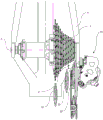
figure 2 shows a bicycle shifter according to the present invention in relation to a bicycle frame and a gear set;
fig. 3 is a front view of the shifter according to the present invention, taken according to a transverse direction with respect to the bicycle (not shown);
fig. 4 is a rear view of the shifter of fig. 3, taken according to a transverse direction with respect to a bicycle (not shown);
figure 5 is a sectional view of the shifter of figure 3 according to the plane V-V;
fig. 6 is an enlarged view of the transmission with variable transmission ratio of the shifter of fig. 3.
Figure 7 (in a similar way to figure 6) shows a transmission of the prior art with fixed transmission ratios;
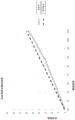
fig. 8 is a graph comparing the characteristics of the transmission with variable transmission ratio (shifter of the invention) of fig. 6 with those of the transmission of fig. 7 (shifter of the prior art), showing the progression of the displacement angle of the driven wheel (sector) with respect to the rotation of the driving wheel (sprocket);
fig. 9 is a top rear schematic view of the shifter of fig. 3 with the longest gear ratio inserted; the position of the chain guide is also schematically shown in the case of an inserted shortest transmission ratio and in the case of an inserted intermediate transmission ratio;
fig. 10 (in a similar way to fig. 9) shows a prior art shifter for comparison;
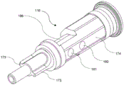
figure 11 is an enlarged view of the components of a transmission with variable transmission ratio according to a second embodiment of the invention;
FIG. 12 is an enlarged view of another component of the transmission with variable transmission ratio according to the embodiment of the invention of FIG. 11;
fig. 13 is a partial cross-sectional view of the shifter according to the embodiment of fig. 11 and 12, taken along the plane XIII-XIII;
figure 14 is a partial cross-sectional view of the shifter of figure 13, taken along the plane XIV-XIV;
fig. 15 is a view similar to fig. 14 during a setting operation of the shifter;
fig. 16 is a front view of some parts of the shifter of fig. 13 in a first set position, said some parts being isolated from the rest of the shifter to better illustrate the features of the invention;
fig. 17 is a rear view of the part of the shifter shown in fig. 16;
figure 18 is a front view of the same part of the shifter shown in figure 16 in a second setting position;
fig. 19 is a rear view of the part of the shifter shown in fig. 18;
the graph of fig. 20 is similar to that of fig. 8, comparing the characteristics of the transmission with variable transmission ratio (shifter of the invention) of fig. 11 to 19 with those of fig. 7 (shifter of the prior art), showing the progression of the displacement angle of the driven wheel (sector) with respect to the rotation of the driving wheel (sprocket); since the transmission of fig. 11 to 19 allows two different setting positions, in the graph of fig. 20 two curves are shown corresponding to the two setting positions;
figures 21 and 22 are graphs derived from the graph of figure 20, in which the curves relating to the two setting positions are shown only in isolation and in an enlarged manner;
figure 23 is a view similar to figure 3 of a third embodiment of the invention;
figure 24 is a cross-sectional view of the shifter of figure 23 according to the planes XXIV-XXIV indicated in figure 23;
fig. 25 is a view similar to fig. 24 during a setting operation of the shifter;
fig. 26 is a partial sectional view of the shifter as shown in fig. 24, taken along the plane XXVI-XXVI;
fig. 27 is a partial sectional view of the shifter as shown in fig. 25, taken along the plane XXVII-XXVII;
fig. 28 is a rear view of the portion of the shifter shown in fig. 26;
figures 29 and 30 are enlarged views of the components of the transmission with variable transmission ratio according to the embodiment of the invention of figures 23 to 28;
fig. 31 is a cross-sectional view of the shifter of fig. 26 and 27, taken along the plane XXXI-XXXI.
Detailed Description
Referring to the drawings, a bicycle shifter is shown, generally indicated at 10.
The indicated bicycle shifter 10 is a rear shifter that moves the drive chain 5 between a plurality of sprockets concentrated in a gear set 2, the gear set 2 having an axis a, associated with the rear wheel 3 of the bicycle 1.
The bicycle shifter 10 comprises an articulated quadrangular link 11 having a base body 12 and a moving body 14, said base body 12 and moving body 14 being connected together by a pair of connecting rods 13, 15, a first connecting rod 13 of said pair being hinged to the base body 12 at a first hinge axis B passing through a first pin 16 and to the moving body 14 at a second hinge axis passing through a second pin 17, and a second connecting rod 15 being hinged to the base body 12 at a third hinge axis passing through a third pin 18 and to the moving body 14 at a fourth hinge axis passing through a fourth pin 19.
The base body 12 is intended to be fixed to the frame 4 of the bicycle 1.
In the articulated quadrilateral 11, the mobile body 14 opposite the base body 12 carries a chain guide 20.
The chain guide 20 comprises a rocker arm 21, the rocker arm 21 carrying an upper roller 22 and a lower roller 23 for the relay chain 5.
For the coupling between the base body 12 and the frame 4, there is a first fixing group 30 to fix said base body 12 to the frame 4 of the bicycle 1, this first fixing group 30 comprising a pin body 31 having an axis C.
The pin body 31 comprises a cylindrical bush 31b and a closing screw 31a, the closing screw 31a being provided with an enlarged head adapted to abut against the base body 12. Cylindrical bushing 31b and closing screw 31a are screwed to each other, thereby holding base body 12 therebetween to prevent axial movement of base body 12 along axis C, but allow base body 12 to rotate.
The closing screw 31a of the pin body 31 engages on a fixing element 40 of the frame 4, the relative angular position of the fixing element 40 with respect to the frame 4 being adjustable.
For this purpose, there is an adjusting screw 41, which adjusting screw 41 engages tangentially on the fixing element 40 and abuts against a projection 42 fixed relative to the frame 4.
Thus, the fixing element 40 and the adjusting screw 41 of the frame 4 constitute an initial setting interface of the relative angular position between the base body 12 and the frame 4.
The purpose of the adjustment of the initial relative angular position between the base body 12 of the articulated quadrangular linkage 11 and the frame 4, which is usually performed during installation, is to adapt the bicycle shifter 10 to different types of frames 4 and gear sets 2, thereby influencing the position that can be occupied by the chain guide 20 relative to such frames 4 and thus relative to the gear sets 2.
The initial setting interfaces 40, 41 of the relative angular position cooperate with a relay element 43, which relay element 43 is provided with a pair of holes 44, 45 and a projection 42 is made on the relay element 43. In particular, the fixing element 40 is inserted in the first hole 44, while the second hole 45 is intended to be fixed to the frame 4 by means of a clamping screw 46.
The anti-lash spring 25 is preferably mounted coaxially on the pin body 31. The term "anti-impact spring" means a spring which is rigid in normal operation but intervenes, in the event of an impact and therefore when external forces intervene beyond a certain limit, by deforming and absorbing them.
In the shifter 10, in the event of an impact, the anti-impact spring 25 transmits its action to the base body 12, allowing a temporary mutual rotation between the base body 12 and the pin body 31, in such a way as to avoid damage to the shifter and in particular to the articulated quadrilateral linkage 11. For this purpose, the first end of the anti-impact spring 25 is indirectly associated with the base body 12 and the second end is associated with the pin body 31.
For the rotational coupling between the moving body 14 and the swing arm 21 of the chain guide 20, there is a fixed group which is conventional per se and which is not illustrated or described in detail below.
An actuating device for actuating the shifter 10 is also provided, which is adapted to modify the configuration of the articulated quadrilateral linkage 11 in order to determine the relative displacement between the moving body 14 and the base body 12, and therefore the displacement of the chain guide 20 with respect to the frame 4.
Such actuating means may be of any of the numerous types known in the art and may be manual or motorized. By way of example only, a sheath mount 50 can be seen which is adapted to receive the end of a manually actuated Bowden cable (not shown).
Although not highlighted in the figures, a clip is provided for fixing the end of the core of the Bowden cable in the articulated quadrangular linkage 11 in a diagonally opposite position with respect to the sheath base 50, so that the traction force exerted by the relative movement between the sheath and the core of the cable determines the deformation of the articulated quadrangular linkage 11.
The pulling action exerted by the relative movement between the sheath and the core of the cable is counteracted by a return spring 51 arranged at the fourth pin 19.
According to the invention, the first fixed group 30 comprises a change mechanism 60 for changing the relative position between the base body 12 of the articulated quadrilateral linkage 11 and the frame 4 according to the main displacement of the chain guide 20, in order to determine a change in the configuration of the chain guide 20.
The changing mechanism 60 for changing the relative position includes a rotating body 61 provided with: at least one sector 62 connected to pin body 31, so that rotation of rotating body 61 determines a relative rotation between pin body 31 and base body 12 about axis C of pin body 31; and at least one sprocket 63, preferably of frustoconical configuration, which sprocket 63 engages the sector 62 so as to impart a commanded rotation to the sector 62.
The sector 62 and the sprocket 63 do not extend 360 ° around the respective axes, but only extend over a much smaller angle, sufficient to meet the operational requirements. In particular, the sector 62 extends over an angle between 45 ° and 90 °, preferably an angle of about 60 °, while the sprocket 63 extends over an angle between 90 ° and 180 °, preferably an angle of about 120 °. The sectors 62 and the sprocket 63 preferably comprise teeth having the same number or a different number of teeth by one, preferably at least equal to four: in the illustrated example, the sector 62 has eight teeth and the sprocket 63 has 7 teeth. The ratio between the angular extension of the sector 62 (driven) and the angular extension of the sprocket 63 (driving) is equal to 1:2.
In particular, the rotating body 61 is constrained to the cylindrical bush 31b of the pin body 31 by means of the interposed anti-impact spring 25. The sprocket 63 is mounted on the pin 16 in a fixed connection, the commanded rotation being applied to the pin 16 so that, at the same time, a displacement of the chain guide 20 is determined having at least one axial component. Thus, the sector 62 and the sprocket 63 together form a gear transmission, which constitutes the transmission between the pin 16 and the rotating body 61.
The changing mechanism 60 for changing the initial relative position is actuated by the relative rotation between the base body 12 of the articulated quadrangular link 11 and the first connecting rod 13. This relative rotation between the base body 12 and the first connecting rod 13 also determines the deformation of the articulated quadrangular link 11 and therefore the main displacement of the chain guide 20 along the axis a.
In order for the rotation between the base body 12 and the connecting rod 13 to determine the rotation of the sprocket 63, the sprocket 63 is fixedly connected to a first pin 16, which first pin 16 in turn is fitted to the first connecting rod 13, i.e. rotates as a unit with the first connecting rod 13 (for example, by polygonal coupling or grooved profile coupling).
In this way, the movement of the first connecting rod 13 causes the movement of the first pin 16, which in turn determines the rotation of the sprocket 63 and therefore of the sector 62 of the rotating body 61 and of the cylindrical bush 31b of the pin body 31.
In this way, a relative rotation between the base body 12 and the pin body 31 of the first fixed group 30, which is related to the axial displacement of the chain guide 20, therefore takes place.
As can be clearly seen in particular in fig. 6, the engagement formed by the sector 62 and by the sprocket 63 is a non-circular gear, in which the teeth are arranged on a non-circular line; thus, each tooth has its own radius relative to its own axis of rotation, and its own radius is different from the own radius of the adjacent tooth. The transmission therefore has a variable transmission ratio between a minimum and a maximum value.
For comparison, fig. 7 shows on the other hand the gears 62TN, 63TN of a similar shifter according to the prior art (corresponding, for example, to the cited document EP 2769907 A1), wherein the transmission has a fixed transmission ratio, with a circular sector 62TN and sprocket 63TN.
Fig. 8 is a graph illustrating the kinematics of the gears 62, 63 of the present invention compared to the kinematics of the gears 62TN, 63TN of the prior art. In particular, it can be seen that in the prior art the relationship between the rotation angle of the driving wheel (sprocket) and the rotation angle of the driven wheel (sector) has a linear progression, whereas in the case of the present invention the progression is not linear: as the rotational angle of the sprocket increases, the slope of the curve increases, i.e., the gear ratio increases.
In particular, the gear ratio in the initial portion may be about 1:4 and in the final portion up to 1:2; in order to be suitable for gear sets with large diameter excursions, for example in the case of a shifter for mountain bikes, it can even reach 1.5 from the initial value of 1:6.
Fig. 9 and 10 illustrate the effect of the different kinematic characteristics described above on the positioning of the chain guide 20, and in particular the rollers 22 thereon. Fig. 9 shows the shifter 10 according to the present invention with the upper roller 22 in three positions, at the even smallest sprocket (longer speed ratio), at the largest sprocket (shorter speed ratio), and at the middle sprocket. Fig. 10 shows a shifter 10TN identical to the shifter 10, except that it comprises gears 62TN, 63TN according to the prior art, i.e. with a constant transmission ratio; in fig. 10, for individual elements, the same reference numerals are used as those of the corresponding elements of the invention, with the addition of the suffix TN. It can thus be seen that at the first and last sprocket of the gearset, the position of the upper roller 22 relative to the gearset 2 is the same as the position of the upper roller 22TN relative to the gearset 2 TN; in contrast, at the intermediate sprocket of gear sets 2, 2TN, the distance d between upper roller 22 and gear set 2 is significantly less than the distance dTN of roller 22TN and gear set 2 TN.
The fact that the chain guide 20 is brought closer to the gear set 2 due to the non-linearity (progressivity) of the transmissions 62, 63 with variable transmission ratio makes it possible to improve the accuracy, sensitivity and speed of the shift at the middle sprocket of the gear set 2 without the risk of causing slip or interference at the larger and smaller sprockets as a result.
Fig. 11 to 19 show a gear selector 110 according to a second exemplary embodiment of the invention, which allows further adjustment possibilities. The shifter 110 according to this embodiment differs from the shifter 10 described above only in the sprockets and pins, only these elements will be described herein; it should be understood that the remaining elements of the shifter 110 are consistent with that described with respect to the shifter 10 and that they will be designated with the same reference numerals only, hereinafter and in the drawings.
In the shifter 10, the sprocket 63 is fitted on the pin 16, whereas in the shifter 110, the sprocket 163 and the pin 116 can be coupled to each other by a coupling, and this coupling makes it possible to mount the sprocket 163 and the pin 116 in at least two different mutual angular positions, allowing a better initial adjustment for the different gear sets.
In this way, the transmission formed by the sprocket 63 together with the sector 62 has a maximum angular offset and a useful angular offset; depending on the desired use of the gear set 2, the useful offset may be selected within limits of maximum offset.
For this purpose, the sprocket 163 comprises a substantially cylindrical axial hole 170, the axial hole 170 being provided with two pairs of opposite lateral seats 171, 172 extending in the radial direction and in the axial direction in the hole 170; the pair of opposing seats 171 are angularly offset from the pair of opposing seats 172 by an angle between 10 ° and 30 °, preferably an angle of about 20 °. Accordingly, the pin 116 includes two opposing fins 173 that extend axially on the pin 116 and radially from the pin 116. If it is desired to enable the device to accommodate a greater number of gear sets, three or more pairs of lateral mounts may be provided.
With reference to the graphs of fig. 20 to 22, the useful angular offset of the transmission, i.e. the angular offset actually used during operation, corresponds to a fraction of the maximum offset and can be adjusted by the positioning of the pin 116. In the example case, the maximum angular offset (drive angle) of sprocket 163 is 130 °, the maximum angular offset (driven angle) of sector 62 is about 45 °, and the transmission ratio is about 1. Fig. 20 shows, in a manner similar to fig. 8, a comparison of the kinematic characteristics of the gear of the present invention with those of the gears of the prior art. According to the chain-dotted line YY in fig. 20, also shown in isolation and in an enlarged manner in fig. 21, when the pin 116 is coupled with the sprocket 163 in the seat 171, its initial and central portions are utilized; in this position, the drive wheel uses an offset of 80 ° and the driven wheel uses an offset of about 25 °; the gear ratio is about 1. According to the dashed line WW in fig. 20, also shown in isolation and enlarged in fig. 22 (where the zero angle in fig. 20 corresponds to an "absolute" angle of about 35 ° on the drive wheel and 10 ° on the driven wheel), the central and final portions of the pin are utilized when it is coupled in the base 172; in this position, the offset used by the drive wheel is 80 °, the offset of the driven wheel is about 30 °, the transmission ratio is about 1, 2.7, which is optimal for a gear set with 11 teeth for the smallest sprocket and 36 teeth for the largest sprocket (i.e., z11 to z 36). In this sense, the shifter of the invention can be defined as "adaptive" in that the coupling mechanism has a variable phase depending on the gear set installed, i.e. it enables selection of which part of the curve of fig. 20 to follow in order to position the part corresponding to the useful angular offset of the transmission differently within the maximum angular offset (see fig. 20 to 22).
The pin 116 is mounted in the connecting rod 13 so as to be movable angularly to the connecting rod 13, but axially along the axis B. For this purpose, the pin 116 comprises a shank 174 with a polygonal cross-section, while the connecting rod 13 comprises a polygonal seat 175 extending along the axis B, shaped to match the shank 174.
In addition, a removable locking device is provided to hold the pin 116 in its coupled or uncoupled position. These removable locking means comprise two recesses 180, 181 formed in the pin 116 on one side of the pin 116, said two recesses 180, 181 being aligned and spaced apart along the axis B and comprising a pointer 183 (in fact, a ball) of rounded shape, which is mounted in a lateral hole 184 formed in the seat 175; a spring 185 is inserted in the side hole 184, which pushes the pointer 183 elastically against the side of the pin 116, so that the pointer 183 is held engaged in one or other of the two recesses 180, 181. The rounded shape of the pointer 183 ensures that: pressure in the direction of axis B can determine disengagement of the pointer 183 from the recesses 180, 181.
In addition, an end stop mechanism is provided for the pin 116 to prevent the pin 116 from sliding completely out of its seat 175 during the initial calibration operation. The end stop mechanism includes a recess 186 on the side of the pin 116, with the pin 187 inserted in a side hole 188 of the seat 175 and engaged in the recess 186.
The shifter 110 further comprises an external indicator indicating the mutual angular position that has been set between the pin 116 and the sprocket 163. The external indicator includes: an indicator 190, the indicator 190 being rotatably mounted on the base body 12 and rotating as a unit with the sprocket 163; and two verification notches 191, 192 formed on the base body 12; depending on which of the bases 171 or 172 the fin 173 is engaged, the indicator 190 is directed toward one or the other of the verification notches 191, 192. In this way it is immediately possible to see externally which setting has been set, and hence with which gear set 2 the shifter can be advantageously used.
Although fig. 11 and 12 illustrate sprocket 163 and pin 116 in isolation, the cross-sections of fig. 13-15 clearly illustrate locking devices 180-185 and end stops 186-188. In particular, the section of fig. 14 shows the coupled position of the pin 116, while the section of fig. 15 shows the uncoupled position thereof.
Fig. 16 to 19 clearly show two possible initial calibration or setting conditions. In particular, in fig. 16 and 17, the fins 173 are engaged in the seat 171, so the indicator 190 is directed towards the verification recess 191, whereas in fig. 18 and 19, the fins 173 are engaged in the seat 172, so the indicator 190 is directed towards the verification recess 192.
Fig. 23 to 31 show a gear shifter 210 according to a third exemplary embodiment of the invention, which allows the same adjustment possibilities as in the second exemplary embodiment. The shifter 210 according to this embodiment differs from the shifter 110 described above only in the removable locking device for retaining the pin, only these components are described here; it should be understood that the remaining elements of the shifter 210 are identical to those described with respect to the shifter 110 and the shifter 10, and only those elements are labeled with the same reference numerals in the following and in the drawings; therefore, in fig. 20 to 22 illustrating the kinematics of the shifter 110, the kinematics of the shifter 210 is also illustrated.
It should be noted that the shifter 210 is of the type having motorized actuation means (generally indicated at 250), which are not illustrated in detail, since they are not relevant per se for the purpose of the present invention.
The pin 216 (as can be seen in particular in fig. 24, 25, 29 and 30) is formed by two coaxial portions 216a and 216b, which two coaxial portions 216a and 216b are coupled together so as to be able to slide axially with respect to each other, while still rotating as a unit; this feature is obtained by prismatic coupling (not visible in the figures). The portion 216a comprises fins 173 and is engaged in the seats 171, 172 with the fins 173, just as in the shifter 110; the portion 216a is also provided with a shaped shank 274 for a keyed coupling in a corresponding shaped portion 277 of the seat 175 of the connecting rod 13. Shaped portion 277 is placed in connecting rod 13 by means of a removable portion 278 (visible in fig. 31) of connecting rod 13 and is connected to the remaining part of connecting rod 13 by means of two screws 279.
The removable locking means for retaining the portion 216a of the pin 216 in its coupled position comprise: a flange 280 on the portion 216 a; and a bolt 283, the bolt 283 being slidably mounted in the slot 284, the slot 284 being laterally open in the base 175 of the connecting rod 13. The bolt 283 is movable between a retaining position (fig. 24 and 26) and a releasing position (fig. 25 and 27); in the retaining position, bolt 283 protrudes inside seat 175 and retains flange 280 of portion 216a of pin 216 so that portion 216a cannot disengage from sprocket 163; in the release position, the bolt 283 is recessed into the slot 284 and does not interfere with the flange 280, allowing the portion 216a to slide axially relative to the portion 216b, disengaging from the sprocket 163. A spring 285 is provided in the slot 284 and urges the bolt 283 toward the retaining position. The slit 284 is provided with side windows 282, the side windows 282 extending longitudinally with respect to the slit 284 and opening toward the outside of the connecting rod 13; through the window 282, the handling portion 281 of the bolt 283 can be manually handled to push the bolt 283 into its release position opposite the spring 285.
Unlike the shifter 110, the shifter 210 does not require an end stop mechanism because it is essentially useless. In fact, only the portion 216a of the pin 216 slides axially, in any case the portion 216a is locked axially inside the seat 175 of the connecting rod 13 by the portion 216b which cannot move axially.
In a completely similar manner to the shifter 110, on the other hand, as can be seen in fig. 28, the shifter 210 is also provided with external indicators 190 to 192.
From the above description and from the drawings, the features and operation of the bicycle shifter of the present invention can be clearly seen, as can the relative advantages.
Due to the change of the initial relative position between the base body of the articulated quadrangular linkage and the pin body of the first fixed group, the relative position between the chain guide and the sprocket can be reached, which makes it possible to obtain, on the one hand, a higher control sensitivity with respect to the prior art shifters and, on the other hand, to reduce the drawbacks associated with the chain guide being too close to the largest diameter sprocket.
Due to the non-linearity of the transmission with variable transmission ratio, it can be ensured in particular that the chain guide is always as close as possible to the sprocket engaging the chain, irrespective of the axial position of the sprocket inside the gear train.
Further variants of the above described embodiments are also possible, which variants are not explicitly described herein, but which are covered by the scope of protection defined by the claims.
For example, it may be provided that the actuating means for actuating the gear shifter are of different types (e.g. electrically actuated) or are arranged to act on the articulated quadrilateral linkage in different ways with respect to the one illustrated.
Claims (16)
1. A bicycle shifter (10
-an articulated quadrilateral linkage (11) having a base body (12) and a moving body (14), the base body (12) and the moving body (14) being connected together by a pair of connecting rods (13, 15) articulated with the base body (12) and the moving body (14),
-a fixing group (30), the fixing group (30) being used for fixing the base body (12) to a bicycle frame (4),
-a chain guide (20) mounted on the moving body (14), the articulated quadrangular linkage (11) being associated with actuation means (50;
wherein the fixed group (30) comprises
-a pin body (31), the pin body (31) having an axis (C) and being used to fix the base body (12) to a frame (4) of a bicycle,
-a change mechanism (60) for changing the relative angular position between the base body (12) of the articulated quadrangular linkage (11) and the frame (4) according to the main displacement of the chain guide (20), wherein the change mechanism (60) for changing the relative angular position between the base body (12) and the frame (4) comprises:
-a rotating body (61), said rotating body (61) being connected to said pin body (31) such that a rotation of said rotating body (61) determines a relative rotation between said pin body (31) and said base body (12) about said axis (C);
-a pin (16,
-transmission means (62, 63, 162, 163) between the pin (16,
it is characterized in that
-said transmission means (62, 63, 162, 163) between said pin (16.
2. The bicycle shifter (10.
3. The bicycle shifter (110.
4. The bicycle shifter (110.
5. The bicycle shifter (110:
-an axial hole (170), said axial hole (170) being formed in said sprocket (163) and being provided with at least two pairs of opposite seats (171, 172) radially extending from said hole (170),
-two opposite fins (173) formed to extend radially on said pin (116, 216) and engaged in a removable manner in one of said pairs of seats (171, 172) in said hole (170) of said sprocket (163).
6. The bicycle shifter (110, 210) of claim 1, wherein the pin (116.
7. The bicycle shifter (110) of claim 6, wherein the pin (116) includes a shank having a polygonal cross-section, and wherein the foot (175) has a corresponding polygonal cross-section.
8. The bicycle shifter (210) according to claim 6, wherein the pin (216) includes a shank (274), the seat (175) in the first connecting rod (13) includes a shaped portion (277) formed by means of a detachable portion (278) of the first connecting rod (13), and the shank (274) has a corresponding shaped cross section.
9. The bicycle shifter (110, 210) of claim 3, wherein the pin (116, 216) is axially movable in a base (175) of a first (13) of the two connecting rods between a retracted coupling position in which the pin is coupled with the sprocket (163) and an extracted decoupling position in which the pin is decoupled from the sprocket (163), wherein a removable locking device is provided for holding the pin (116.
10. The bicycle shifter (110) of claim 9, wherein the removable locking device comprises:
-two recesses (180, 181) formed in the pin (116) and aligned and spaced apart in the direction of the axis (B) of the pin (116),
a pointer (183) mounted in a side hole (184) formed in the seat (175) of the first connecting rod (13),
-an elastic element (185) in the side hole (184), the elastic element (185) elastically pressing the pointer (183) in a radial direction to hold the pointer in engagement with one or the other of the two recesses (180, 181).
11. The bicycle shifter (210) of claim 9, wherein the removable locking device comprises:
-a slit (284) open laterally on the seat (175) of the first connecting rod (13),
-a lateral window (282) of the slit (284), arranged longitudinally with respect to the slit (284) and facing the outside of the first connecting rod (13),
-a bolt (283) mounted in said slit (284) in such a way as to be movable between a retaining position, in which it projects inside the seat (175) of the first connecting rod (13) and retains the pin (216) in a withdrawn coupling position of the pin (216) with the sprocket (163), and a release position, in which it does not project in the seat (175) of the first connecting rod (13) and allows to place the pin (216) in an extracted uncoupling position in which the pin (216) is extracted from the sprocket (163),
-a resilient element (285) pushing the bolt (283) into its retaining position,
-a handling portion (281) of the bolt, protruding from the side window (282), so as to be actuatable to move the bolt (283) in opposition to the elastic element (285).
12. The bicycle shifter (110) according to claim 9, the bicycle shifter (110) comprising an end stop mechanism (186-188) of the pin (116) to prevent the pin from being withdrawn from the seat (175) of the first connecting rod (13) beyond the extracted position.
13. The bicycle shifter (110) according to claim 3 or 4, the bicycle shifter (110) comprising an external indicator (190-192) of the mutual angular position between the pin (116).
14. A method for performing a gear shift in a bicycle shifter (10:
-engaging the drive chain (5) with the chain guide (20),
-exerting a primary displacement on the chain guide (20) in an axial direction relative to the gear set (2) to move the drive chain (5) between the sprockets of the gear set (2),
-simultaneously exerting an auxiliary displacement on the chain guide (20) in a radial direction with respect to the gear set (2) to move the chain guide (20) towards the gear set (2) when the drive chain (5) moves from a larger sprocket to a smaller sprocket, whereas to move the chain guide (20) away from the gear set (2) when the drive chain (5) moves from a smaller sprocket to a larger sprocket,
it is characterized in that
The secondary displacement has a greater amount when the primary displacement occurs in a region of the gear set including the largest sprocket and a lesser amount when the primary displacement occurs in a region of the gear set including the smallest sprocket.
15. The method according to claim 14, wherein the auxiliary displacement is adjustable in dependence of the gear set (2) installed in the shifter (110, 210).
16. The method of claim 15, wherein the secondary displacement is obtained by the primary displacement with a transmission having a maximum offset and a useful offset, the useful offset extending only in a portion of the maximum offset, wherein the secondary displacement is adjustable by selecting the useful offset of the transmission within the maximum offset.
Applications Claiming Priority (2)
| Application Number | Priority Date | Filing Date | Title |
|---|---|---|---|
| IT102018000009245 | 2018-10-08 | ||
| IT102018000009245A IT201800009245A1 (en) | 2018-10-08 | 2018-10-08 | Bicycle shifting with high control precision and method for making a shift in a bicycle shift |
Publications (2)
| Publication Number | Publication Date |
|---|---|
| CN111003099A CN111003099A (en) | 2020-04-14 |
| CN111003099B true CN111003099B (en) | 2023-04-11 |
Family
ID=65010822
Family Applications (1)
| Application Number | Title | Priority Date | Filing Date |
|---|---|---|---|
| CN201910931936.9A Active CN111003099B (en) | 2018-10-08 | 2019-09-29 | Bicycle shifter with high precision control and method of shifting gears in a bicycle shifter |
Country Status (6)
| Country | Link |
|---|---|
| US (1) | US11433972B2 (en) |
| EP (1) | EP3636536B1 (en) |
| JP (1) | JP2020075702A (en) |
| CN (1) | CN111003099B (en) |
| IT (1) | IT201800009245A1 (en) |
| TW (1) | TWI807111B (en) |
Families Citing this family (1)
| Publication number | Priority date | Publication date | Assignee | Title |
|---|---|---|---|---|
| TWI729557B (en) * | 2019-11-06 | 2021-06-01 | 天心工業股份有限公司 | Rear derailleur |
Family Cites Families (26)
| Publication number | Priority date | Publication date | Assignee | Title |
|---|---|---|---|---|
| US5620383A (en) * | 1995-02-06 | 1997-04-15 | Sram Corporation | Bicycle derailleur and actuating system |
| IT1320581B1 (en) * | 2000-08-03 | 2003-12-10 | Campagnolo Srl | FRONT BIKE FRONT DERAILLEUR WITH ELECTRIC CONTROL MOTOR AND GEAR REDUCER. |
| IT1321071B1 (en) * | 2000-11-17 | 2003-12-30 | Campagnolo Srl | ACTUATOR DEVICE FOR A BIKE FRONT DERAILLEUR, WITH CONNECTION JOINT TO THE DRIVEN SHAFT. |
| US20030083162A1 (en) * | 2001-10-26 | 2003-05-01 | Sunrace Roots Enterprise Co., Ltd. | Rear derailleur of a bicycle |
| CN1224787C (en) * | 2002-04-25 | 2005-10-26 | 周祖焕 | Fish-shaped gear and infinitely gearbox for bicycle |
| EP1504989B1 (en) * | 2003-08-05 | 2012-03-21 | Campagnolo S.R.L. | Actuator device and relative nut for a bicycle gearshift, with an elastically yieldind member |
| ITMO20040107A1 (en) * | 2004-05-06 | 2004-08-06 | L A M S R L | CHANGE FOR BICYCLE |
| JP2006137206A (en) * | 2004-11-10 | 2006-06-01 | Shimano Inc | Electrical component for bicycle and derailleur for bicycle using the same |
| JP2006219029A (en) * | 2005-02-10 | 2006-08-24 | Shimano Inc | Electric driving device for bicycle |
| US8419573B2 (en) * | 2005-07-28 | 2013-04-16 | Shimano Inc. | Bicycle rear derailleur |
| US8066597B2 (en) * | 2007-03-15 | 2011-11-29 | Shimano, Inc. | Electrically operated derailleur with force overload protection |
| US8137223B2 (en) * | 2007-05-16 | 2012-03-20 | Shimano Inc. | Bicycle rear derailleur |
| US7942767B2 (en) * | 2007-12-19 | 2011-05-17 | Shimano, Inc. | Bicycle derailleur with multiple mounting adjustments |
| US20110224035A1 (en) * | 2010-03-15 | 2011-09-15 | Kristopher Wehage | Derailleur for Bicycle |
| ITMI20130251A1 (en) | 2013-02-22 | 2014-08-23 | Campagnolo Srl | CHANGE OF BICYCLE WITH IMPROVED COMMAND PRECISION |
| ITMI20130253A1 (en) * | 2013-02-22 | 2014-08-23 | Campagnolo Srl | MOTORIZED BICYCLE CHANGE WITH DRIVE SHIFTING THE CRANKSHAFT |
| ITMI20130252A1 (en) * | 2013-02-22 | 2014-08-23 | Campagnolo Srl | CHANGE OF BICYCLE WITH IMPROVED COMMAND PRECISION |
| US9085340B1 (en) * | 2014-03-14 | 2015-07-21 | Tien Hsin Industries Co., Ltd. | Electronic front derailleur |
| ITMI20142069A1 (en) * | 2014-12-02 | 2016-06-02 | Campagnolo Srl | DERAILLEUR OF A BICYCLE CHANGE AND METHOD OF ELECTRONICALLY CONTROL OF A BICYCLE CHANGE |
| US9656723B1 (en) * | 2015-12-14 | 2017-05-23 | Shimano Inc. | Electrical bicycle derailleur |
| US9950769B2 (en) * | 2016-05-20 | 2018-04-24 | Tien Hsin Industries Co., Ltd. | Electric front derailleur |
| ITUA20163996A1 (en) * | 2016-05-31 | 2017-12-01 | Campagnolo Srl | Electric bicycle derailleur |
| IT201600128989A1 (en) * | 2016-12-20 | 2018-06-20 | Campagnolo Srl | Bicycle rear derailleur |
| US10793222B1 (en) * | 2017-03-21 | 2020-10-06 | Jonathan K. Harris | Bicycle derailleur having upper and lower alignment assemblies |
| US11697474B2 (en) * | 2020-06-30 | 2023-07-11 | Shimano Inc. | Bicycle derailleur and link pin for bicycle derailleur |
| US11745828B2 (en) * | 2020-06-30 | 2023-09-05 | Shimano Inc. | Front derailleur and chain guide of bicycle derailleur |
-
2018
- 2018-10-08 IT IT102018000009245A patent/IT201800009245A1/en unknown
-
2019
- 2019-09-26 JP JP2019176015A patent/JP2020075702A/en active Pending
- 2019-09-29 CN CN201910931936.9A patent/CN111003099B/en active Active
- 2019-10-01 EP EP19200883.7A patent/EP3636536B1/en active Active
- 2019-10-03 US US16/592,056 patent/US11433972B2/en active Active
- 2019-10-07 TW TW108136249A patent/TWI807111B/en active
Also Published As
| Publication number | Publication date |
|---|---|
| US20200108890A1 (en) | 2020-04-09 |
| EP3636536A1 (en) | 2020-04-15 |
| JP2020075702A (en) | 2020-05-21 |
| TW202023895A (en) | 2020-07-01 |
| EP3636536B1 (en) | 2021-01-27 |
| IT201800009245A1 (en) | 2020-04-08 |
| TWI807111B (en) | 2023-07-01 |
| CN111003099A (en) | 2020-04-14 |
| US11433972B2 (en) | 2022-09-06 |
Similar Documents
| Publication | Publication Date | Title |
|---|---|---|
| US8240448B2 (en) | Parking device of transmission | |
| US9505462B2 (en) | Bicycle gearshift with improved precision control | |
| EP3381787B1 (en) | Bicycle rear derailleur | |
| CN103154557B (en) | Disk type braker and manufacture method thereof | |
| EP3339159B1 (en) | Rear derailleur of a bicycle | |
| US20140243129A1 (en) | Bicycle gearshift with improved precision control | |
| CN108482574B (en) | Actuating device for actuating a front derailleur of a bicycle | |
| US20030094328A1 (en) | Motor vehicle with automatic transmission | |
| US20150274255A1 (en) | Actuator device for a bicycle gearshift and nut for such a device | |
| CN111003099B (en) | Bicycle shifter with high precision control and method of shifting gears in a bicycle shifter | |
| CN103249964A (en) | Output member and multi-haft drive device | |
| US10442499B2 (en) | Actuation device for the control cable of a bicycle gearshift | |
| TW201742785A (en) | Actuator device for a bicycle gearshift and respective bicycle gearshift | |
| CN108146576B (en) | Actuating device for control cable of bicycle speed variator | |
| JP2007520669A (en) | Gear shift device | |
| EP3246241B1 (en) | Actuator device for a bicycle gearshift and respective bicycle gearshift | |
| US10676155B2 (en) | Device for actuating a front derailleur of a bicycle | |
| DE102019214113B4 (en) | Shift fork arrangement, actuating arrangement with the shift fork arrangement, manual transmission with the actuating arrangement, motor vehicle with the manual transmission, and a method for engaging a gear of the manual transmission. | |
| KR20060113094A (en) | Parking device for an auto transmission |
Legal Events
| Date | Code | Title | Description |
|---|---|---|---|
| PB01 | Publication | ||
| PB01 | Publication | ||
| SE01 | Entry into force of request for substantive examination | ||
| SE01 | Entry into force of request for substantive examination | ||
| GR01 | Patent grant | ||
| GR01 | Patent grant |