CN110955048B - Head-mounted display device - Google Patents
Head-mounted display device Download PDFInfo
- Publication number
- CN110955048B CN110955048B CN201910910872.4A CN201910910872A CN110955048B CN 110955048 B CN110955048 B CN 110955048B CN 201910910872 A CN201910910872 A CN 201910910872A CN 110955048 B CN110955048 B CN 110955048B
- Authority
- CN
- China
- Prior art keywords
- temple
- head
- display device
- case
- mounted display
- Prior art date
- Legal status (The legal status is an assumption and is not a legal conclusion. Google has not performed a legal analysis and makes no representation as to the accuracy of the status listed.)
- Active
Links
- 239000002184 metal Substances 0.000 claims description 8
- 210000003128 head Anatomy 0.000 description 34
- 210000001508 eye Anatomy 0.000 description 29
- 230000000694 effects Effects 0.000 description 13
- 238000002347 injection Methods 0.000 description 10
- 239000007924 injection Substances 0.000 description 10
- 230000000052 comparative effect Effects 0.000 description 6
- 238000006073 displacement reaction Methods 0.000 description 6
- 238000005452 bending Methods 0.000 description 5
- 210000005069 ears Anatomy 0.000 description 4
- 239000011521 glass Substances 0.000 description 4
- 238000009434 installation Methods 0.000 description 4
- 230000007480 spreading Effects 0.000 description 4
- 238000003892 spreading Methods 0.000 description 4
- 230000003287 optical effect Effects 0.000 description 3
- 238000003825 pressing Methods 0.000 description 3
- 210000005252 bulbus oculi Anatomy 0.000 description 2
- 238000005401 electroluminescence Methods 0.000 description 2
- 230000004438 eyesight Effects 0.000 description 2
- 238000004519 manufacturing process Methods 0.000 description 2
- 229920000089 Cyclic olefin copolymer Polymers 0.000 description 1
- 230000037237 body shape Effects 0.000 description 1
- 238000010586 diagram Methods 0.000 description 1
- 210000001061 forehead Anatomy 0.000 description 1
- 238000004898 kneading Methods 0.000 description 1
- 239000004973 liquid crystal related substance Substances 0.000 description 1
- 239000000463 material Substances 0.000 description 1
- 238000012986 modification Methods 0.000 description 1
- 230000004048 modification Effects 0.000 description 1
- 230000002093 peripheral effect Effects 0.000 description 1
- 210000001747 pupil Anatomy 0.000 description 1
- 239000011347 resin Substances 0.000 description 1
- 229920005989 resin Polymers 0.000 description 1
- 210000001525 retina Anatomy 0.000 description 1
- 238000000926 separation method Methods 0.000 description 1
- 238000002834 transmittance Methods 0.000 description 1
Images


Classifications
-
- G—PHYSICS
- G02—OPTICS
- G02B—OPTICAL ELEMENTS, SYSTEMS OR APPARATUS
- G02B27/00—Optical systems or apparatus not provided for by any of the groups G02B1/00 - G02B26/00, G02B30/00
- G02B27/01—Head-up displays
- G02B27/017—Head mounted
- G02B27/0176—Head mounted characterised by mechanical features
-
- G—PHYSICS
- G02—OPTICS
- G02B—OPTICAL ELEMENTS, SYSTEMS OR APPARATUS
- G02B27/00—Optical systems or apparatus not provided for by any of the groups G02B1/00 - G02B26/00, G02B30/00
- G02B27/01—Head-up displays
- G02B27/017—Head mounted
- G02B27/0172—Head mounted characterised by optical features
-
- G—PHYSICS
- G02—OPTICS
- G02B—OPTICAL ELEMENTS, SYSTEMS OR APPARATUS
- G02B27/00—Optical systems or apparatus not provided for by any of the groups G02B1/00 - G02B26/00, G02B30/00
- G02B27/01—Head-up displays
- G02B27/0179—Display position adjusting means not related to the information to be displayed
-
- G—PHYSICS
- G02—OPTICS
- G02C—SPECTACLES; SUNGLASSES OR GOGGLES INSOFAR AS THEY HAVE THE SAME FEATURES AS SPECTACLES; CONTACT LENSES
- G02C5/00—Constructions of non-optical parts
- G02C5/001—Constructions of non-optical parts specially adapted for particular purposes, not otherwise provided for or not fully classifiable according to technical characteristics, e.g. therapeutic glasses
-
- G—PHYSICS
- G02—OPTICS
- G02C—SPECTACLES; SUNGLASSES OR GOGGLES INSOFAR AS THEY HAVE THE SAME FEATURES AS SPECTACLES; CONTACT LENSES
- G02C5/00—Constructions of non-optical parts
- G02C5/14—Side-members
- G02C5/146—Side-members having special front end
-
- G—PHYSICS
- G02—OPTICS
- G02B—OPTICAL ELEMENTS, SYSTEMS OR APPARATUS
- G02B27/00—Optical systems or apparatus not provided for by any of the groups G02B1/00 - G02B26/00, G02B30/00
- G02B27/01—Head-up displays
- G02B27/017—Head mounted
- G02B2027/0178—Eyeglass type
-
- G—PHYSICS
- G02—OPTICS
- G02B—OPTICAL ELEMENTS, SYSTEMS OR APPARATUS
- G02B27/00—Optical systems or apparatus not provided for by any of the groups G02B1/00 - G02B26/00, G02B30/00
- G02B27/01—Head-up displays
- G02B27/0179—Display position adjusting means not related to the information to be displayed
- G02B2027/0187—Display position adjusting means not related to the information to be displayed slaved to motion of at least a part of the body of the user, e.g. head, eye
-
- G—PHYSICS
- G02—OPTICS
- G02C—SPECTACLES; SUNGLASSES OR GOGGLES INSOFAR AS THEY HAVE THE SAME FEATURES AS SPECTACLES; CONTACT LENSES
- G02C11/00—Non-optical adjuncts; Attachment thereof
- G02C11/10—Electronic devices other than hearing aids
-
- G—PHYSICS
- G02—OPTICS
- G02C—SPECTACLES; SUNGLASSES OR GOGGLES INSOFAR AS THEY HAVE THE SAME FEATURES AS SPECTACLES; CONTACT LENSES
- G02C2200/00—Generic mechanical aspects applicable to one or more of the groups G02C1/00 - G02C5/00 and G02C9/00 - G02C13/00 and their subgroups
- G02C2200/22—Leaf spring
Abstract
Provided is a head-mounted display device which has improved wearability. A head-mounted display device includes: a frame extending in a 1 st direction; a display unit that emits image light in a 2 nd direction intersecting the 1 st direction; a housing which is mounted on one end of the frame in the 1 st direction and accommodates a part of the display unit; and a temple arranged on a center side in the 1 st direction of the head-mounted display device with respect to the housing, the housing including: a side surface located on the arrangement side of the temple; and a 1 st recess that opens in the 2 nd direction on a side surface, and a 1 st gap is formed between the 1 st recess and a temple arranged along the side surface.
Description
Technical Field
The present invention relates to a head-mounted display device.
Background
Conventionally, a head-mounted display device is known which is worn on the head of a user and displays an image so as to be visually recognizable to the user. As such a head mounted display device, a head mounted display having a pair of temples suspended from the left and right ears of a user is known (for example, see patent document 1).
The head mounted display described in patent document 1 includes a 1 st display device, a 2 nd display device, a frame portion, and an inner frame that is detachable from the frame portion and the like and is adjustable in accordance with the eyesight and body shape of an observer as a user. The 1 st display device is configured by combining a 1 st light guide device which covers the eyes of an observer in a see-through manner and a 1 st image forming main body portion which is attached to the frame portion. The 2 nd display device is also configured by combining the 2 nd light guide device and the 2 nd image forming main body portion which are the same as the 1 st light guide device and the 1 st image forming main body portion. The frame portion has an exterior member covering the 1 st image forming main body portion and an exterior member covering the 2 nd image forming main body portion.
The internal frame is provided between the 1 st display device and the 2 nd display device that bear the optical structure of the head mounted display. The inner frame has a pair of frame portions into which spectacle lenses for vision correction are inserted, a pair of temples extending rearward from both left and right ends of the pair of frame portions, and a nose pad attached to a central portion between the pair of frame portions.
The inner frame is disposed in front of the eyes of the observer via a nose pad supported by the nose and a pair of temples supported by the side head such as the ears or temples, and the head mounted display is worn on the observer.
Documents of the prior art
Patent document
Patent document 1: japanese patent laid-open publication No. 2016-180939
Disclosure of Invention
Problems to be solved by the invention
Since the head mounted display described in patent document 1 is configured such that the internal frame can be replaced for each viewer, it is necessary to secure a space for replacing the internal frame between the 1 st display device and the 2 nd display device. Therefore, the distance between the 1 st display device and the 2 nd display device needs to be increased, and the size of the head mounted display is likely to be increased.
In contrast, it is conceivable to reduce the size of the head-mounted display device by providing a right side support portion for rotatably supporting the right side temple on the right side outer case of the observer and providing a left side support portion for rotatably supporting the left side temple on the left side outer case of the observer. In order to improve the wearability on the head, the following configuration is considered: the right side support portion is provided on the left side surface of the right outer case, and the left side support portion is provided on the right side surface of the left outer case, whereby the right temple and the left temple are disposed in the vicinity of the head of the observer.
However, in a state where the extended left temple is in contact with the right side surface of the left outer case and the extended right temple is in contact with the left side surface of the right outer case, when the left temple is to be unfolded outward, a fulcrum at which the left temple is flexed outward becomes a contact point located at the rearmost position between the left temple and the left outer case. The same applies to the case where the right side temples are to be spread outward.
Therefore, when the fulcrum of the deflection of each temple is located at the rear end of the left outer case and the right outer case, the range of the deflection of each temple is small, and therefore, the user may not easily wear the head-mounted display device. This is particularly remarkable in the case where a user with a small head is to wear a head-mounted display device.
In this situation, a head-mounted display device having improved wearability is desired.
Means for solving the problems
A head-mounted display device according to an aspect of the present invention includes: a frame extending in a 1 st direction; a display unit that emits image light in a 2 nd direction intersecting the 1 st direction; a housing attached to one end of the frame in the 1 st direction and configured to accommodate a part of the display unit; and a temple arranged on a center side in the 1 st direction of the head-mounted display device with respect to the housing, the housing including: a side surface located on the arrangement side of the temple; and a 1 st recess that opens in the 2 nd direction at the side surface, and a 1 st gap is formed between the 1 st recess and the temple arranged along the side surface.
In the above aspect, it is preferable that the temple has a 2 nd recessed portion into which a part of the case is fitted in an arrangement state along the side surface.
In the above aspect, it is preferable that the temple has a protruding portion that abuts the side surface in an arrangement state in which the temple is arranged along the side surface, and the protruding portion has elasticity.
In the above aspect, the temple preferably has an opening portion surrounding a part of the protruding portion.
In the above aspect, it is preferable that the case has a temple support portion provided on the side surface and supporting the temple, the temple has a 1 st link and a 2 nd link, the 1 st link and the 2 nd link sandwich the temple support portion in a 3 rd direction intersecting with the 1 st direction and the 2 nd direction, respectively, and are supported by the temple support portion, and the temple support portion includes: a 1 st mounting part to which the 1 st connecting part is mounted; and the 2 nd installation department, it supplies the 2 nd connecting portion to install, in 3 rd direction the 1 st installation department with be provided with the 2 nd clearance between the 2 nd installation department.
In the above aspect, it is preferable that the display unit includes: an image emitting unit that is disposed in the housing along the 2 nd direction and emits the image light; and a light guide unit arranged along the 1 st direction and configured to guide the image light emitted from the image emitting unit to a predetermined viewing position.
In the above aspect, it is preferable that the case has a temple support portion provided on the side surface and supporting the temple, and the temple support portion is disposed in a direction opposite to the 2 nd direction with respect to a center of the 2 nd direction in the side surface.
In the above aspect, it is preferable that the frame is formed of metal, and the image emitting portion is fixed to the frame.
In the above aspect, it is preferable that the housing has an inner housing provided in the housing, and the inner housing has an upright portion located between the image emitting portion and the side surface.
Drawings
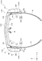
Fig. 1 is a perspective view showing a head-mounted display device in embodiment 1.
Fig. 2 is a perspective view showing the head mounted display device in embodiment 1.
Fig. 3 is a plan view showing the head-mounted display device according to embodiment 1.
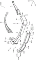
Fig. 4 is an exploded perspective view showing the head mounted display device in embodiment 1.
Fig. 5 is an exploded perspective view showing a head-mounted display device according to embodiment 1.
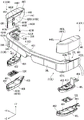
Fig. 6 is an exploded perspective view showing the support portion in embodiment 1.
Fig. 7 is an exploded perspective view showing a display unit and a support unit in embodiment 1.
Fig. 8 is an exploded perspective view showing a display unit and a support unit in embodiment 1.
Fig. 9 is a perspective view showing a temple on the left side in embodiment 1.
Fig. 10 is a perspective view showing a temple on the left side in embodiment 1.
Fig. 11 is a perspective view showing the temple on the right side in embodiment 1.
Fig. 12 is a perspective view showing the right temple in embodiment 1.
Fig. 13 is a plan view showing the head-mounted display device according to embodiment 1 with the upper case removed.
Fig. 14 is a sectional view showing the left temple and the left side case in embodiment 1.
Fig. 15 is a plan view showing a head-mounted display device according to a comparative example in embodiment 1.
Fig. 16 is a plan view showing the head-mounted display device according to embodiment 1.
Fig. 17 is a plan view showing the head-mounted display device according to embodiment 2.
Description of the reference symbols
1A, 1B: a head-mounted display device; 2A, 2B: a device main body; 3: a display unit; 3L: a left side display section; 3R: a right display section; 31L: a left side emitting section (image emitting section); 31R: a right side emitting section (image emitting section); 36L: a left light guide portion (light guide portion); 36R: a right light guide portion (light guide portion); 4: a support portion; 41: assembling the components; 42: a frame; 43L, 63L: a left side case (housing); 43R, 63R: a right side case (case); 443L, 443R: a shaft support portion (temple support portion); 43L1, 43R 1: an abutting surface; 43L2, 43R 2: an inclined surface; 43LX, 63LX, 43RX, 63 RX: a side surface; 43L3, 43R3, 63L3, 63R 3: a recess (1 st recess); 44LY, 44 RY: kneading; 444L, 444R: 1 st installation part; 446L, 446R: a 2 nd mounting part; 448: a step portion; 45L, 45R: an inner housing; 452: a standing part; 5L, 5R: a temple; 5L2, 5R 2: a 1 st connecting part; 5L3, 5R 3: a 2 nd connecting part; 5L5, 5R 5: a recess (2 nd recess); 5L7, 5R 7: a protrusion; 5L8, 5R 8: an opening part; GL1, GR 1: a gap (2 nd gap); GL2, GR 2: a gap (1 st gap); NP: a nose pad.
Detailed Description
[ embodiment 1 ]
Next, embodiment 1 of the present invention will be described with reference to the drawings.
[ schematic Structure of head-mounted display device ]
Fig. 1 and 2 are perspective views of the head-mounted display device 1A according to the present embodiment as viewed from the front side upward and the rear side downward. Fig. 3 is a plan view of the head mounted display device 1A as viewed from above.
The Head-Mounted Display device 1A according to the present embodiment is a so-called Head Mounted Display (HMD) that is used so as to be Mounted on the Head of a user and displays an image so as to be visually recognizable to the user. As shown in fig. 1 to 3, the head-mounted display device 1A includes a device main body 2A, and the device main body 2A includes a display unit 3, a support unit 4, temples 5L and 5R, and a nose pad NP. In addition, the head-mounted display device 1A may include a cover member that is attached to the device main body 2A and covers the left light guide portion 36L and the right light guide portion 36R constituting the display unit 3 on the front side.
As will be described in detail later, the display unit 3 includes a left display unit 3L and a right display unit 3R that display images, respectively. The support portion 4 includes a fitting 41, a frame 42, a left side case 43L, and a right side case 43R, and the support portion 4 supports the display portion 3, the temples 5L, 5R, and the nose pad NP. The temples 5L and 5R are suspended on the left and right ears of the user, and the nose pad NP abuts the nose of the user, whereby the head-mounted display device 1A is mounted on the head of the user.
Next, the structure of the head-mounted display device 1A will be described in detail.
In the following description, 3 directions perpendicular to each other are defined as a + X direction, a + Y direction, and a + Z direction, and a direction from the back surface to the front surface of the head-mounted display device 1A is defined as a + Z direction. Further, a direction from the right to the left when the head-mounted display device 1A is viewed from the + Z direction is defined as a + X direction, and a direction from the bottom to the top when the head-mounted display device 1A is viewed from the + Z direction is defined as a + Y direction.
Although not shown, for convenience of explanation, the directions opposite to the + X direction, + Y direction, and + Z direction are assumed to be the-X direction, -Y direction, and-Z direction.
In the present embodiment, the 2 nd direction, which is a direction in which the display unit 3 described later emits image light, is the-Z direction. The 1 st direction in which the frame 42 extends is the + X direction, and the direction intersecting the 1 st direction and the 2 nd direction is the + Y direction. Specifically, the + X direction as the 1 st direction is a direction from the left display section 3L to the right display section 3R out of the left display section 3L and the right display section 3R constituting the display section 3. The + X direction is a direction from the left emission portion 31L constituting the left display portion 3L toward the right emission portion 31R constituting the right display portion 3R. Further, the + X direction is a direction from the shaft support portion 443L of the support temple 5L in the left casing 43L toward the shaft support portion 443R of the support temple 5R in the right casing 43R.
In addition, for the user wearing the head-mounted display device 1A, the + X direction is a direction from the left to the right, the + Y direction is a direction from the lower side to the upper side, and the + Z direction is a direction from the rear side to the front side.
Therefore, in the configuration of the head-mounted display device 1A, "L" is assigned to the reference numeral of the configuration disposed on the left side of the user, i.e., in the-X direction, and "R" is assigned to the reference numeral of the configuration disposed on the right side of the user, i.e., in the + X direction.
[ Structure of support part ]
Fig. 4 and 5 are exploded perspective views showing the head-mounted display device 1A viewed from the front side upper side and the rear side lower side. In detail, fig. 4 and 5 are exploded perspective views showing the head-mounted display device 1A in which the attachment member 41 of the support portion 4 and the temples 5L and 5R are separated.
Here, the support portion 4 will be described first.
The support portion 4 supports the display portion 3 and the nose pad NP, and rotatably supports the temples 5L and 5R. As shown in fig. 4 and 5, the support portion 4 includes a fitting 41, a frame 42, a left side case 43L, and a right side case 43R.
[ Structure of Assembly Member ]
The attachment member 41 is fixed to the right case 43R and the left case 43L so as to cover the frame 42 and the right light guide portion 36R and the left light guide portion 36L constituting the display unit 3 in the + Z direction. The mounting member 41 is a portion to which the cover member is detachably mounted in the + Z direction.
The mounting member 41 includes a main body 411 disposed in the + Z direction with respect to the left and right light guide portions 36L and 36R, and fixing portions 415L and 415R extending in the-Z direction from the main body 411.
The main body 411 includes a left frame 413L forming a left opening 412L and a right frame 413R forming a right opening 412R. In addition, as shown in fig. 5, the main body 411 includes magnets 414L and 414R for attracting the cover member.
As shown in fig. 4 and 5, the left frame portion 413L is positioned in the + Z direction with respect to the left light guide portion 36L, and the left frame portion 413L surrounds a region including a display region of the left-eye image displayed by the left light guide portion 36L when viewed from the + Z direction.
The right frame portion 413R is positioned in the + Z direction with respect to the right light guide portion 36R, and the right frame portion 413R surrounds a region including the display region of the right-eye image displayed by the right light guide portion 36R when viewed from the + Z direction.
When the user views the outside world through the left and right light guide portions 36L and 36R, the user's line of sight passes through the left and right opening portions 412L and 412R.
As shown in fig. 5, the magnet 414L is provided at a corner in the-X direction and the + Y direction of the surface of the main body 411 in the-Z direction. The magnet 414R is provided at a corner in the + X direction and the + Y direction on the surface in the-Z direction of the main body 411.
As shown in fig. 4 and 5, the fixing portion 415L is provided at a position near an end in the-X direction in the main body portion 411. The fixing portion 415L includes an upper arm portion 4151 extending in the-Z direction from an end edge in the + Y direction in the body 411, and a lower arm portion 4153 extending in the-Z direction from an end edge in the-Y direction in the body 411.
The fixing portion 415R is provided in the vicinity of the end portion in the + X direction of the body 411, and includes an upper arm portion 4151 and a lower arm portion 4153, as with the fixing portion 415L.
The upper arm 4151 and the lower arm 4153 of the fixing portion 415L are fixed to a later-described shaft support portion 443L of the left housing 43L by screws SL, and the upper arm 4151 and the lower arm 4153 of the fixing portion 415R are fixed to a shaft support portion 443R of the right housing 43R by screws SR, whereby the mounting member 41 is fixed to the left housing 43L and the right housing 43R.
[ Structure of frame ]
Fig. 6 is an exploded perspective view showing the support portion 4. In detail, fig. 6 is a perspective view of the frame 42 and the left and right cases 43L and 43R after separating the upper cases 44L and 44R and the lower cases 46L and 46R from each other from the back side. Fig. 7 and 8 are exploded perspective views showing the display unit 3 and the support unit 4. In detail, fig. 7 and 8 are exploded perspective views of the right and left display units 3R and 3L, the right and left cases 43R and 43L, respectively, as viewed from the front side upward and the rear side downward.
The frame 42 is a metal member having a substantially U shape when viewed from the + Y direction, and is disposed along the + X direction which is the 1 st direction. That is, one end of the frame 42 is located in the-X direction and the other end is located in the + X direction.
As shown in fig. 6 to 8, the frame 42 includes a front end 421 extending along the forehead of the user, and side portions 422L and 422R extending in the-Z direction from ends of the front end 421 in the ± X direction.
The front end 421 is a portion along the XZ plane in the frame 42. The distal end portion 421 supports a nose pad NP disposed between the light guide portions 36L and 36R, in addition to the left light guide portion 36L and the right light guide portion 36R, which will be described later, of the display portion 3.
Of the front end 421, a right end 421R in the + X direction and a left end 421L in the-X direction are curved in a circular arc shape in the-Z direction when viewed from the + Y direction.
The side surface portion 422R extends in the-Z direction from the right end portion 421R. A case fixing portion 423R is provided at an end in the-Z direction of the surface in the-X direction of the side surface portion 422R, and the case fixing portion 423R fixes an inner case 45R, which will be described later, of the right side case 43R.
A lens barrel fixing portion 424R is provided at a position in the + Y direction where the side surface portion 422R and the distal end portion 421 intersect, and the lens barrel fixing portion 424R fixes a lens barrel 35R of a right emission portion 31R described later constituting the right display portion 3R.
The side surface portion 422L extends in the-Z direction from the left end 421L. A case fixing portion 423L is provided at an end portion in the-Z direction of the + X direction surface of the side surface portion 422L, and the case fixing portion 423L fixes an internal case 45L, which will be described later, of the left case 43L.
A lens barrel fixing portion 424L is provided at a position in the + Y direction where the side surface portion 422L and the distal end portion 421 intersect, and the lens barrel fixing portion 424L fixes a lens barrel 35L constituting a left emission portion 31L described later of the left display portion 3L.
[ Structure of left side case ]
The left housing 43L is attached to an end portion of the frame 42 in the-X direction, and houses a left emission portion 31L of the left display portion 3L, which will be described later.
As shown in fig. 6 to 8, the left side case 43L includes an upper case 44L, an inner case 45L, and a lower case 46L.
[ Structure of Upper casing ]
The upper case 44L covers the left emission portion 31L in the + Y direction. In detail, the upper case 44L is a box-shaped case arranged as follows: the lens barrel 35L and the side surface portion 422L constituting the left side injection portion 31L are accommodated inside through an opening 441 that opens in the-Y direction, and cover the lens barrel 35L and the side surface portion 422L in the + Y direction, the ± X direction, and the ± Z direction.
The upper case 44L has an opening 442, a shaft support 443L provided on the + X direction surface 44LX, and a step 448 provided on the + Y direction surface 44 LY.
The opening 442 is an opening that: when upper case 44L is attached to frame 42, front end 421 and left light guide 36L are arranged therein.
The shaft support portion 443L is a portion: in addition to rotatably supporting the temple 5L, the fixing portion 415L of the attachment member 41 is fixed. That is, the shaft support portion 443L is a temple support portion that supports the temple 5L. The axial support portion 443L is positioned in the + Z direction from the center in the-Z direction, which is the 2 nd direction, of the side surface of the left side case 43L on the temple 5L side, that is, the + X direction side surface 43LX including the surface 44 LX. In detail, the shaft support portion 443L is provided at the end in the + Z direction of the surface 44 LX. Therefore, the shaft support portion 443L is disposed in the vicinity of an intersection portion where the lens barrel 35L of the later-described left light emitting portion 31L disposed along the-Z direction, which is the 2 nd direction, and the later-described left light guide portion 36L disposed along the + X direction, which is the 1 st direction, intersect on the surface 44 LX.
The shaft bearing portion 443L has a 1 st mounting portion 444L located in the + Y direction and a 2 nd mounting portion 446L located in the-Y direction.
The 1 st attachment portion 444L has a screw hole 445L into which the screw SL (see fig. 4) is screwed, and the screw SL penetrates the upper arm portion 4151 of the attachment portion 415L and a through hole 5L21, which will be described later, of the temple 5L in the-Y direction.
The 2 nd mounting portion 446L has a screw hole 447L into which a screw, not shown, is screwed, and the screw is inserted in the + Y direction through the lower arm portion 4153 of the fixing portion 415L and a through hole 5L31 of the temple 5L, which will be described later.
The 1 st mounting portion 444L and the 2 nd mounting portion 446L are disposed at a predetermined interval in the + Y direction. In other words, in the + Y direction as the 3 rd direction, a gap GL1 as a 2 nd gap is formed between the 1 st mounting part 444L and the 2 nd mounting part 446L. The gap GL1 is a portion where the left leg of the eyeglasses is disposed when the user wearing the eyeglasses wears the head-mounted display device 1A.
The stepped portion 448 is a portion recessed in the-Y direction along the end edge in the-X direction in the + Y direction surface 44 LY. When the temple 5L axially supported by the shaft support portion 443L is disposed along the + Z direction, the stepped portion 448 is disposed in the recessed portion 5L5 of the temple 5L.
[ Structure of inner case ]
The inner case 45L is a component of: lens barrel 35L of left-side emission unit 31L is fixed to lens barrel 35L so as to cover the same from the-Y direction, and supports control unit 32L located in the-Y direction. That is, the inner case 45L is disposed in a space formed by combining the upper case 44L and the lower case 46L. The inner case 45L has a mounting portion 451, an upright portion 452, a support portion 453, and a fixing portion 454.
The mount portion 451 is a portion fixed to the lens barrel 35L and is located on the surface in the + Y direction.
The standing portion 452 is a rib standing from an end edge in the + X direction in the surface in the + Y direction to the + Y direction.
The support portion 453 is a portion that supports the control portion 32L constituting the left side injection portion 31L, and is positioned on the surface in the-Y direction.
The fixing portion 454 is a portion fixed to the case fixing portion 423L of the side surface portion 422L, and is located at an end in the-Z direction.
[ Structure of lower casing ]
The lower case 46L covers the inner case 45L in the-Y direction, and is combined with the upper case 44L to house the left injection portion 31L. The lower case 46L has a connecting portion 461 and fixing portions 462 and 463.
The connection portion 461 stands in the + Y direction from the peripheral edge of the surface in the + Y direction in the lower case 46L, and is connected to the end edge of the opening 441 in the upper case 44L. The inner case 45L is disposed inside the connection portion 461.
The fixing portion 462 is located in the + Z direction, and the fixing portion 463 is located in the-Z direction. The fixing portion 462 is fixed to the inner case 45L fixed to the frame 42 via the lens barrel 35L, and the fixing portion 463 is fixed to the upper case 44L. Thus, the upper case 44L, the inner case 45L, and the lower case 46L are combined to form the left case 43L.
The side surface 43LX in the + X direction in the left side case 43L is a side surface facing the center of the head-mounted display device 1A in the + X direction. The side surface 43LX is constituted by a surface 44LX in the + X direction in the upper case 44L and a surface 46LX in the + X direction in the lower case 46L. As shown in fig. 3, the-Z direction portion of the side surface 43LX is inclined so as to be located in the-X direction as it goes to the-Z direction. That is, the side surface 43LX has: an abutment surface 43L1 located at a position in the + Z direction, extending along the temple 5L and abutting against the temple 5L; and an inclined surface 43L2 located in the-Z direction and located in the-X direction, which is a direction away from the temple 5L as it goes toward the-Z direction. Thus, the left side case 43L is cut away in the-Z direction obliquely in the + X direction. In other words, the left side case 43L has a recess 43L3 as a 1 st recess, the recess 43L3 opens in the-Z direction, and a gap GL2 as a 1 st gap is formed between the left side case 43L and a temple 5L in an extended state described later.
The function and effect of the gap GL2 will be described in detail later.
[ Structure of Right side case ]
As shown in fig. 7 and 8, the right side case 43R includes an upper case 44R, an inner case 45R, and a lower case 46R, and the upper case 44R, the inner case 45R, and the lower case 46R have mirror-symmetrical structures with the upper case 44L, the inner case 45L, and the lower case 46L, respectively.
The inner case 45R includes a mounting portion 451, an upright portion 452, a support portion 453, and a fixing portion 454, as in the inner case 45L. The lower case 46R has a connecting portion 461 and fixing portions 462 and 463, as in the lower case 46L.
The inner case 45R and the lower case 46R are mirror-symmetrical to the inner case 45L and the lower case 46L, and therefore, detailed description thereof is omitted.
The upper case 44R is attached to the end of the frame 42 in the + X direction, and is combined with the lower case 46R to house the right injection portion 31R. Similarly to the upper case 44L, the upper case 44R has an opening 442, a shaft support portion 443R provided on the surface 44RX in the-X direction, and a stepped portion 448 provided on the surface 44RY in the + Y direction.
The shaft support portion 443R is a portion including: in addition to rotatably supporting the temple 5R, the fixing portion 415R of the attachment member 41 is fixed. That is, the shaft support portion 443R is a temple support portion that supports the temple 5R. The axial support portion 443R is positioned in the + Z direction from the center in the-Z direction, which is the 2 nd direction, of the side surface of the right side case 43R on the temple 5R side, that is, the + X direction side surface 43RX including the surface 44 RX. In detail, the shaft support portion 443R is provided at the end in the + Z direction of the surface 44 RX. Therefore, the shaft supporting portion 443R is disposed in the vicinity of an intersection portion where the lens barrel 35R of the right emitting portion 31R described later disposed along the-Z direction, which is the 2 nd direction, and the right light guiding portion 36R described later disposed along the + X direction, which is the 1 st direction, intersect on the surface 44 RX.
The shaft bearing portion 443R has a 1 st mounting portion 444R in the + Y direction and a 2 nd mounting portion 446R in the-Y direction.
The 1 st attachment portion 444R has a screw hole 445R into which the screw SR (see fig. 4) is screwed, and the screw SR is inserted in the-Y direction through the upper arm portion 4151 of the fixing portion 415R and a through hole 5R21 of the temple 5R, which will be described later.
The 2 nd mounting portion 446R has screw holes 447R into which screws, not shown, are screwed, and the screws are inserted in the + Y direction through the lower arm portion 4153 of the fixing portion 415R and through holes 5R31, which will be described later, of the temples 5R.
The 1 st mounting portion 444R and the 2 nd mounting portion 446R are disposed at a predetermined interval in the + Y direction. In other words, in the + Y direction as the 3 rd direction, a gap GR1 as a 2 nd gap is formed between the 1 st mounting portion 444R and the 2 nd mounting portion 446R. Similarly to the gap GL1, the gap GR1 is a portion where the right leg of the eyeglasses is disposed when the user wearing the eyeglasses wears the head-mounted display device 1A.
The side surface 43RX in the-X direction in the right side case 43R is a side surface facing the center in the + X direction of the head mounted display device 1A. The side surface 43RX is constituted by a surface 44RX in the-X direction in the upper case 44R and a surface 46RX in the-X direction in the lower case 46R. As shown in fig. 3, the portion of the side surface 43RX in the-Z direction is inclined so as to be located in the + X direction as it goes toward the-Z direction. That is, the side surface 43RX has: an abutment surface 43R1 located at a position in the + Z direction, extending along the temple 5R and abutting against the temple 5R; and an inclined surface 43R2 located in the-Z direction and located in the + X direction, which is a direction away from the temple 5R as it goes toward the-Z direction. Thus, the right side case 43R obliquely cuts off a portion in the-Z direction in the-X direction. In other words, the right side case 43R has a recess 43R3 as a 1 st recess, the recess 43R3 opens in the-Z direction, and a gap GR2 as a 1 st gap is formed between the right side case 43R and a temple 5R in an extended state described later.
The function and effect of the gap GR2 are described in detail later.
[ Structure of display part ]
The display unit 3 emits image light to a predetermined viewing position and displays an image formed by the image light. The predetermined viewing position is a position of an exit pupil formed by an optical system constituting the display unit 3. In the present embodiment, the predetermined viewing position is set as a virtual position corresponding to the left eye and the right eye of the user.
As shown in fig. 6 to 8, the display unit 3 includes a left display unit 3L that emits left-eye image light to the left eye of a user in one viewing position to display a left-eye image, and a right display unit 3R that emits right-eye image light to the right eye of a user in another viewing position to display a right-eye image.
[ Structure of left display part ]
The left display section 3L is located in the-X direction in the head-mounted display device 1A. The left display unit 3L includes a left emitting unit 31L as an image emitting unit that emits left-eye image light for forming a left-eye image, and a left light guide unit 36L as a light guide unit that guides the emitted left-eye image light to the left eye of the user.
The left emitting portion 31L is accommodated in the left housing 43L, and forms and emits left-eye image light corresponding to image information input from the outside. The left emission part 31L includes a control part 32L, an image forming part 33L, and an image projecting part 34L.
The control unit 32L outputs an image signal corresponding to the input image information to the image forming unit 33L, and causes the image forming unit 33L to form left-eye image light corresponding to the image information. As shown in fig. 7 and 8, the control portion 32L is supported by the inner case 45L.
The image forming unit 33L is connected to the control unit 32L via a flexible printed circuit board, not shown, and forms left-eye image light corresponding to an image signal input from the control unit 32L. In the present embodiment, the image forming unit 33L is formed of a self-luminous display panel such as an organic EL (Electro-Luminescence) panel. However, the image forming section 33L is not limited to this, and may be configured by a combination of a light source such as an LED and an optical modulation device such as a device using a micromirror such as a liquid crystal panel or a MEMS mirror.
The image projecting section 34L projects the left-eye image light formed by the image forming section 33L to the left light guide section 36L. As shown in fig. 6 and 8, the image projection unit 34L includes a lens barrel 35L and a lens or a prism, not shown, disposed in the lens barrel 35L. The lens barrel 35L is integrated with the image forming section 33L, the lens barrel 35L is fixed to a barrel fixing section 424L of the frame 42 along the-Z direction which is the 2 nd direction, and an inner case 45L is fixed to the lens barrel 35L.
As described above, the left light guide 36L is supported by the frame 42 and is disposed along the + X direction, which is the 1 st direction, at a position corresponding to the left eye of the user, as shown in fig. 6 to 8. The left light guide unit 36L internally reflects the left-eye image light emitted from the image projection unit 34L at the interface, guides the light in the + X direction, and emits the light to the left eye through a semi-transmissive layer provided in accordance with the eyeball of the left eye of the user. That is, the left display unit 3L emits the left-eye image light from the left light guide unit 36L in the-Z direction, which is the 2 nd direction.
The left light guide 36L is made of, for example, a resin such as a cycloolefin polymer that exhibits high light transmittance in a visible light region, and a user can observe the outside world through the left light guide 36L.
[ Structure of Right-side display part ]
The right display section 3R is located in the + X direction in the apparatus main body 2A. As shown in fig. 6 to 8, the right display unit 3R includes a right emitting unit 31R serving as an image emitting unit that emits right-eye image light for forming a right-eye image, and a right light guide unit 36R serving as a light guide unit that guides the emitted right-eye image light to the right eye of the user.
The right emitting section 31R is housed in the right casing 43R, and forms and emits right-eye image light corresponding to image information input from the outside. The right emitting portion 31R includes a control portion 32R, an image forming portion 33R, and an image projecting portion 34R, as in the left emitting portion 31L.
The control unit 32R outputs an image signal corresponding to the input image information to the image forming unit 33R, and causes the image forming unit 33R to form right-eye image light corresponding to the image information. The control portion 32R is supported by the inner case 45R.
The image forming unit 33R forms right-eye image light corresponding to the image signal input from the control unit 32R.
The image projection unit 34R includes a lens barrel 35R and a lens or a prism that is disposed in the lens barrel 35R and projects the right-eye image light to the right light guide unit 36R. The lens barrel 35R is integrated with the image forming unit 33R, the lens barrel 35R is fixed to a right end 421R of the frame 42 along the-Z direction as the 2 nd direction, and the inner case 45R is fixed to the lens barrel 35R.
As described above, right light guide 36R is supported by frame 42 and is disposed along the + X direction, which is the 1 st direction, at a position corresponding to the right eye of the user. The right light guide unit 36R internally reflects the right-eye image light emitted from the right emission unit 31R at the interface, guides the light in the-X direction, and emits the light to the right eye through a semi-transmissive layer provided according to the eyeball of the right eye of the user. That is, the right display unit 3R emits right-eye image light for forming a right-eye image from the right light guide unit 36R in the-Z direction, which is the 2 nd direction. The right light guide part 36R is made of, for example, the same light-transmitting material as the left light guide part 36L, and a user can observe the outside world through the right light guide part 36R.
In this way, the apparatus main body 2A is a see-through head-mounted display apparatus in which the user can view an image and the outside simultaneously.
[ Structure of temples ]
As shown in fig. 3, the temple 5L is supported by the shaft support portion 443L of the left casing 43L so as to be rotatable about a rotation shaft along the + Y direction in the + DL1 direction and the-DL 1 direction.
The temple 5R is supported by the shaft support portion 443R of the right casing 43R so as to be rotatable about a rotation shaft along the + Y direction in the + DR1 direction and the-DR 1 direction. When the user wears the head-mounted display device 1A on the head, the temples 5L, 5R are elongated in the-Z direction and suspended on the left and right ears of the user. That is, the temples 5L and 5R are attachment members for attaching the head-mounted display device 1A to the head of the user.
The + DL1 direction is a direction in which the temple 5L is spread outward, is a direction away from the temple 5R, and is clockwise when viewed from the + Y direction. the-DL 1 direction is the opposite direction of the + DL1 direction, which is the direction in which the temple 5L is folded inward, which is the direction approaching the temple 5R, and which is counterclockwise when viewed from the + Y direction. The + DR1 direction is a direction in which the temple 5R is spread outward, is a direction away from the temple 5L, and is a counterclockwise direction when viewed from the + Y direction. the-DR 1 direction is the opposite direction of the + DR1 direction, is the direction in which the temple 5R is folded inward, is the direction approaching the temple 5L, and is clockwise when viewed from the + Y direction.
The temples 5L and 5R are arranged in an extended state such that the extending direction from the shaft supports 443L and 443R extends along the-Z direction. The temples 5L and 5R are bent at the shaft support portions 443L and 443R such that the extending directions extending from the shaft support portions 443L and 443R are along the + X direction and the-X direction.
Each direction in the following description of the temples 5L, 5R is each direction when the temples 5L, 5R are in the extended state.
[ Structure of temple on left side ]
Fig. 9 is a perspective view of the temple 5L in an extended state as viewed from the + X direction and the + Y direction, and fig. 10 is a perspective view of the temple 5L in an extended state as viewed from the-X direction and the-Y direction.
As shown in fig. 3, the temple 5L is positioned in the + X direction with respect to the left ejection portion 31L provided in the left casing 43L. In other words, the temple 5L is positioned on the center side of the head-mounted display device 1A in the + X direction with respect to the left side emitting portion 31L.
As shown in fig. 9 and 10, the temple 5L has an extension 5L1 and a temple 5L9, and is formed in a shape corresponding to the left head of the user.
The extension 5L1 is a portion of the temple 5L from the support position of the shaft support portion 443L to a position corresponding to the left ear of the user. The extension 5L1 is formed in an arc shape as follows: the bending is performed in the-X direction from the end in the + Z direction toward the-Z direction, and then in the + X direction toward the-Z direction.
The extending portion 5L1 includes a 1 st link portion 5L2, a 2 nd link portion 5L3, a placement portion 5L4, a recess portion 5L5, a protruding strip portion 5L6, a protruding portion 5L7, and an opening portion 5L 8.
The 1 st link 5L2 and the 2 nd link 5L3 project from the end of the extending portion 5L1 in the + Z direction and are support positions of the shaft support 443L. The 1 st land 5L2 is located in the + Y direction, and the 2 nd land 5L3 is located in the-Y direction.
The 1 st connecting portion 5L2 is disposed between the 1 st mounting portion 444L and the upper arm portion 4151 of the fixing portion 415L. That is, the 1 st connecting portion 5L2 is arranged in the + Y direction with respect to the 1 st mounting portion 444L. The 1 st link portion 5L2 has through holes 5L21 through which the screws SL (see fig. 4) inserted into the upper arm portion 4151 are inserted, and the screws SL inserted into the through holes 5L21 are screwed into the screw holes 445L.
The 2 nd connecting portion 5L3 is disposed between the 2 nd mounting portion 446L and the lower arm portion 4153 of the fixing portion 415L. That is, the 2 nd connecting part 5L3 is arranged in the-Y direction with respect to the 2 nd mounting part 446L. The 2 nd connecting portion 5L3 has a through hole 5L31 through which a screw, not shown, inserted into the lower arm portion 4153 is inserted, and the screw inserted into the through hole 5L31 is screwed into the screw hole 447L.
Thereby, the temple 5L is rotatably supported by the shaft support portion 443L.
As shown in fig. 9, the arrangement portion 5L4 is a concave portion that is located on the + X direction side surface 5L11 of the extension portion 5L1 and is concave in the-X direction. The placement unit 5L4 is a location where the temple (leg) of the glasses is placed when the head-mounted display device 1A is worn on the head of the user wearing the glasses.
The recessed portion 5L5 corresponds to the 2 nd recessed portion, and as shown in fig. 10, is formed by a protruding strip portion 5L6 protruding in the-X direction from the end in the + Y direction in the side surface 5L12 in the-X direction in the extending portion 5L 1. In detail, the recessed portion 5L5 is a recessed portion that is located closer to the-Y direction than the protruding portion 5L6 and is recessed in the + X direction. The recessed portion 5L5 is a portion where a part of the left side case 43L is disposed when the temple 5L is in the extended state. That is, the recessed portion 5L5 is a portion into which the protruding strip 5L6 covers the stepped portion 448 (see fig. 6) of the left casing 43L in the + Y direction and into which a portion in the + X direction of the left casing 43L is fitted.
The protrusion 5L7 is located in the + Z direction in the extension 5L1 and abuts against the + X direction side surface 43LX of the left side case 43L. The protruding portion 5L7 protrudes toward the side surface 43LX and abuts against the side surface 43 LX.
The opening 5L8 is an opening that surrounds the three directions of ± Y direction and-Z direction in the protruding portion 5L7 and penetrates the temple 5L in the + X direction. That is, the protrusion 5L7 is connected to the extension 5L1 at the + Z direction.
Since the opening 5L8 is formed around the projection 5L7, the projection 5L7 has elasticity to be displaceable in the-X direction. The operation and effect of the protrusion 5L7 will be described in detail later.
The temple 5L9 is a part disposed along a part behind the left ear of the user, and suppresses the head-mounted display device 1A from shifting from the head. The temple 5L9 is formed continuously with the extension portion 5L1 at a portion of the extension portion 5L1 on the side opposite to the shaft support portion 443L, that is, on the side opposite to the 1 st link portion 5L2 and the 2 nd link portion 5L 3. The temple 5L9 extends while bending in the + X direction and the-Y direction as it goes to the-Z direction. That is, the distal end portion of the temple 5L9 is positioned closer to the-Y direction than the end edge in the + Y direction in the extension portion 5L 1.
[ Structure of temple on the right side ]
Fig. 11 is a perspective view of the temple 5R in an extended state as viewed from the-X direction and the + Y direction, and fig. 12 is a perspective view of the temple 5R in an extended state as viewed from the + X direction and the-Y direction.
As shown in fig. 6 and 7, the temple 5R is positioned in the-X direction with respect to the right injection part 31R provided in the right housing 43R. In other words, the temple 5R is located on the center side in the + X direction of the head mounted display device 1A with respect to the right side emitting portion 31R. The temple 5R can be rotated in the ± DR1 direction within the rotation range between the extended state and the bent state about the shaft supporting portion 443R.
The temple 5R has a mirror-symmetrical configuration with respect to the temple 5L. Specifically, as shown in fig. 11 and 12, the temple 5R includes an extension 5R1 and a temple 5R9, the extension 5R1 includes a side 5R11 in the-X direction and a side 5R12 in the + X direction, and the temple 5R is formed in a shape corresponding to the right head of the user.
That is, the extension 5R1 is a portion of the temple 5R from the support position of the shaft support portion 443R to a position corresponding to the right ear of the user. The extension portion 5R1 is formed in an arc shape as follows: the bending is performed in the + X direction from the end in the + Z direction toward the-Z direction, and then in the-X direction toward the-Z direction.
The extending portion 5R1 includes the 1 st connecting portion 5R2, the 2 nd connecting portion 5R3, the arrangement portion 5R4, the recess 5R5, the ridge 5R6, the protruding portion 5R7, and the opening portion 5R8, which are the same as the 1 st connecting portion 5L2, the 2 nd connecting portion 5L3, the arrangement portion 5L4, the recess 5L6, the protruding portion 5L7, and the opening portion 5L 8. The 1 st connector 5R2 has a through hole 5R21, and the 2 nd connector 5R3 has a through hole 5R 31.
The temple 5R9 is a part disposed along a part behind the right ear of the user, and sandwiches the head together with the temple 5R9 to suppress the head-mounted display device 1A from shifting from the head. The temple 5R9 extends while bending in the-X direction and the-Y direction as it goes to the-Z direction.
[ function of protruding part of temple ]
As described above, since the opening 5L8 surrounding the protruding portion 5L7 in three directions is formed, the protruding portion 5L7 has elasticity capable of being displaced in the + X direction. Therefore, when the extending portion 5L1 abuts against the side surface 43LX, the extending portion 5L1 is rotated in the direction away from the side surface 43LX, i.e., -DL1, by the elasticity of the protruding portion 5L 7.
Similarly, since the opening 5R8 is formed, the protrusion 5R7 has elasticity that enables displacement in the-X direction. Therefore, when the extending portion 5R1 abuts against the side surface 43RX, the extending portion 5R1 is rotated in the direction of separation from the side surface 43RX, that is, in the direction of — DR1, by the elasticity of the protruding portion 5R 7.
Thus, for example, when a user with a small head wears the head-mounted display device 1A, the temples 5L and 5R appropriately press the head, and the wearing feeling of the head-mounted display device 1A is improved.
Fig. 13 is a plan view of the head-mounted display device 1A with the upper cases 44L and 44R removed, as viewed from the + Y direction. In other words, fig. 13 is a view showing the contact portion of the protruding portion 5L7 with the left side case 43L and the contact portion of the protruding portion 5R7 with the right side case 43R.
Here, as shown in fig. 13, the contact portion of the protruding portion 5L7 with the left case 43L is a portion in the-Z direction in the side surface 43 LX. In detail, the contact portion of the protrusion 5L7 is an inclined surface 43L2 located closer to the-Z direction than the portion corresponding to the left injection portion 31L in the side surface 43 LX. Similarly, the contact portion of the protruding portion 5R7 with the right casing 43R is an inclined surface 43R2 of the side surface 43RX located in the-Z direction with respect to the portion corresponding to the right injection portion 31R.
Therefore, even when the temples 5L and 5R are arranged in the extended state or the like and the protruding portions 5L7 and 5R7 apply a high pressing force to the side surfaces 43LX and 43RX, deformation of the side surfaces 43LX and 43RX or displacement of the lens barrel 35L arranged in the left housing 43L and the lens barrel 35R arranged in the right housing 43R are suppressed.
The lens barrels 35L and 35R are fixed to lens barrel fixing portions 424L and 424R of the frame 42, which is a metal member. Therefore, displacement of the lens barrels 35L, 35R is also suppressed.
Fig. 14 is a view showing a cross section of the temple 5L and the left side case 43L along the YZ plane. In other words, fig. 14 is a diagram showing a part of a cross section of the head-mounted display device 1A in the XIV-XIV line in fig. 3. In fig. 14, a part of the structure of the left injection portion 31L and the left housing 43L is omitted for illustration.
As described above, the left side case 43L has the inner case 45L disposed inside the upper case 44L and the lower case 46L combined with each other. As shown in fig. 14, the standing portion 452 of the inner case 45L is located between the lens barrel 35L and the side surface 43LX in the + X direction.
Therefore, even if the side surface 43LX tries to deform due to the pressing force of the protruding portion 5L7, the standing portion 452 suppresses the deformation of the side surface 43LX, and suppresses the displacement of the lens barrel 35L.
The same applies to the inner case 45R of the right case 43R.
[ Effect of the gap between the left side case and the left side temple and the gap between the right side case and the right side temple ]
Fig. 15 is a plan view of the head mounted display device HD which is a comparative example of the head mounted display device 1A seen from the + Y direction.
Here, in the head mounted display device 1A, the functions of the gap GL2 between the left side case 43L and the temple 5L in the extended state and the gap GR2 between the right side case 43R and the temple 5R in the extended state are described in comparison with the head mounted display device HD in which the gaps GL2 and GR2 are not provided.
As shown in fig. 15, the head-mounted display device HD has the same structure as the head-mounted display device 1A except that a left side case HL and a right side case HR are provided instead of the left side case 43L and the right side case 43R. That is, the head-mounted display device HD includes a left housing HL accommodating the left emitting portion 31L, a temple 5L rotatably supported by the left housing HL, a right housing HR accommodating the right emitting portion 31R, and a temple 5R rotatably supported by the right housing HR.
The left side case HL has the same structure as the left side case 43L, but has a different outer shape from the left side case 43L. Specifically, in the left side casing HL, a side surface HL1 in the + X direction on the temple 5L side is formed in a shape along the temple 5L in the extended state in a range from the shaft support portion 443L provided at the end in the + Z direction to the end in the-Z direction of the left side casing HL. That is, the left side case HL has no recess 43L 3.
The right casing HR also has the same configuration as the right casing 43R, but has a different outer shape from the right casing 43R. Specifically, in the right casing HR, a side face HR1 in the-X direction on the temple 5R side is formed in a shape extending along the temple 5R in the extended state in a range from the shaft support portion 443R provided at the end in the + Z direction to the end in the-Z direction of the right casing HR. That is, the right side casing HR does not have the recess 43R 3.
In other words, in the + X direction with respect to the left casing HL, there is no gap GL2 between the left casing HL and the temple 5L, and in the-X direction with respect to the right casing HR, there is no gap GR2 between the right casing HR and the temple 5R.
The dimensions in the + Z direction of the left and right cases HL and HR are the same as those of the left and right cases 43L and 43R.
When the user intends to extend the temples 5L and 5R in the extended state outward by wearing the head-mounted display device HD on the head, the part of the temple 5L in the-Z direction extends outward from the contact part with the left casing HL, and the part of the temple 5R in the-Z direction extends outward from the contact part with the right casing HR.
That is, when the temple 5L is applied with a force spreading in the direction of DL2, which is the outer side, the temple 5L supported by the left casing HL flexes in the direction of DL2 with the end HL2 in the-Z direction in the left casing HL as a fulcrum.
Similarly, when the temple 5R is applied with a force spreading in the direction DR2, which is the outer side, the temple 5R supported by the right casing HR flexes in the direction DR2 with the end HR2 in the-Z direction in the right casing HR as a fulcrum. In this case, 2/3 in the-Z direction of the entire temple 5L, 5R partially flexes outward.
However, in this case, the + Z direction portions of the temples 5L and 5R are not easily bent, and therefore, the bending amounts of the temples 5L and 5R are insufficient, and the wearing feeling of the head-mounted display device HD to the head of the user, particularly the wearing feeling of the head-mounted display device HD to the head of the user whose head is small, may be insufficient.
Fig. 16 is a plan view of the head mounted display device 1A as viewed from the + Y direction. In other words, fig. 16 is a plan view showing the position of the fulcrum of the flexure of the temples 5L, 5R in the head-mounted display device 1A.
As shown in fig. 16, the left casing 43L of the head mounted display device 1A has a recess 43L3 in a region in the + X direction and the-Z direction on the temple 5L side with respect to the left casing HL of the head mounted display device HD as a comparative example. In addition, the right side case 43R of the head mounted display device 1A has a recessed portion 43R3 in a region in the-X direction and the-Z direction which is the side closer to the temple 5R, with respect to the right side case HR of the head mounted display device HD which is the comparative example. Thus, a gap GL2 is formed between the left side case 43L and the extended temple 5L, and a gap GR2 is formed between the right side case 43R and the extended temple 5R.
Further, in the left side case 43L, the abutment surface 43L1 in the + Z direction in the side surface 43LX in the + X direction is in contact with the temple 5L. Therefore, when the temple 5L is applied with a force spreading in the direction of DL2, which is the outer side, the temple 5L flexes in the direction of DL2 with the end 43L11 in the-Z direction of the abutment surface 43L1 as a fulcrum.
Also, in the right side case 43R, the abutment surface 43R1 in the + Z direction in the side surface 43RX in the-X direction is in contact with the temple 5R. Therefore, when the temple 5R is applied with a force spreading in the DR2 direction as the outer side, the temple 5R bends in the DR2 direction with the end 43R11 in the-Z direction of the abutment surface 43R1 as a fulcrum.
In this way, in the head-mounted display device 1A, the temples 5L and 5R are deflected in the DL2 direction and the DR2 direction with the ends 43L11 and 43R11 in the + Z direction as fulcrums than the ends HL2 and HR2 in the head-mounted display device HD as a comparative example.
Accordingly, since the temples 5L and 5R can be greatly flexed as compared with the head-mounted display device HD, the wearing feeling of the head-mounted display device 1A on the head of the user, particularly the wearing feeling of the head-mounted display device 1A on the head of the user whose head is small, can be improved.
[ Effect of embodiment 1 ]
According to the head mounted display device 1A of the present embodiment described above, the following effects can be exhibited.
The head-mounted display device 1A includes: a frame 42 extending in the + X direction as the 1 st direction; a display unit 3 that emits image light in a-Z direction that is a 2 nd direction intersecting the 1 st direction; a left housing 43L and a right housing 43R as housings which are attached to both ends in the + X direction in the frame 42 and which house the left emitting portion 31L and the right emitting portion 31R as parts of the display unit 3; and temples 5L, 5R arranged on the center side in the + X direction of the head-mounted display device 1A with respect to the left side case 43L and the right side case 43R. The left side case 43L has: a side surface 43LX located on the temple 5L side; and a recess 43L3 as a 1 st recess that opens in the-Z direction in the side surface 43LX and forms a 1 st gap GL2 with the temple 5L arranged along the side surface 43 LX. The same applies to the right side case 43R.
With this configuration, the fulcrum of the deflection of the temples 5L, 5R can be positioned in the + Z direction, as compared with the head-mounted display device HD as the comparative example described above. Therefore, the temples 5L, 5R can be easily flexed, and the amount of flexure of the temples 5L, 5R can be increased. Therefore, the wearing feeling of the head-mounted display device 1A on the head of the user can be improved.
The temple 5L has a recess 5L5 as a 2 nd recess, and this recess 5L5 fits in a part of the left side case 43L in an extended state in which the temple 5L is disposed along the side surface 43LX of the left side case 43L on the temple 5L side. In the extended state of the temple 5L, the protruding portion 5L6 protruding toward the left side case 43L in the temple 5L covers the step portion 448 on the surface of the left side case 43L in the + Y direction. The temple 5R also has the same recess 5R5 and protrusion 5R 6.
According to this structure, a part of the left casing 43L is covered in the + Y direction by the temple 5L in the extended state. This ensures a space for housing the left emission part 31L, and allows the left case 43L to be seen small when the temple 5L is extended, that is, when the head-mounted display device 1A is mounted on the head. The right side case 43R and the temple 5R can also exhibit the same effect. Therefore, the appearance of the head-mounted display device 1A can be improved.
The temple 5L has a protruding portion 5L7 that abuts the side surface 43LX in an extended state arranged along the side surface 43LX, and the protruding portion 5L7 has elasticity.
With this configuration, the protruding portion 5L7 abuts against the side surface 43LX, and thereby the temple 5L rotates toward the center side in the + X direction of the head-mounted display device 1A. Thus, for example, when the head-mounted display device 1A is worn on the head of a user with a small head, appropriate pressure can be applied to the head of the user. Therefore, the wearing feeling of the head-mounted display device 1A can be improved.
Further, the protruding portion 5L7 has elasticity, and thus the temple 5L can be made to follow the side surface 43 LX. Therefore, when the head-mounted display device 1A is worn on the head of a user with a large head, the distance between the temples 5L and 5R can be widened, and the protrusion 5L7 can be prevented from becoming an obstacle.
The same effect can be exerted by the temple 5R having the same structure as the temple 5L.
The temple 5L has an opening 5L8 surrounding portions in the ± Y direction and the-Z direction, which are parts of the protrusion 5L 7. Similarly, the temple 5R has an opening 5R8 surrounding a part of the protrusion 5R7, i.e., the ± Y direction and the-Z direction.
With this structure, the projections 5L7, 5R7 can be easily elastically deformed. In addition, since it is not necessary to provide the protruding portions 5L7 and 5R7 as separate members from the temples 5L and 5R, the manufacturing process of the temples 5L and 5R can be simplified, and the manufacturing cost can be reduced.
The left side case 43L has a shaft support 443L provided on the side surface 43LX and serving as a temple support portion that supports the temple 5L. The temple 5L includes the 1 st link 5L2 and the 2 nd link 5L3, and the 1 st link 5L2 and the 2 nd link 5L3 sandwich the shaft support portion 443L in the + Y direction, which is the 3 rd direction intersecting with the 1 st direction and the 2 nd direction, respectively, and are supported by the shaft support portions 443L, respectively. The shaft support portion 443L includes a 1 st attaching portion 444L to which the 1 st connecting portion 5L2 is attached, and a 2 nd attaching portion 446L to which the 2 nd connecting portion 5L3 is attached. In the + Y direction, a gap GL1 as a 2 nd gap is formed between the 1 st mounting part 444L and the 2 nd mounting part 446L.
With this configuration, when the user wearing the glasses wears the head-mounted display device 1A, the leg portions of the glasses can be arranged in the gap GL 1. Therefore, interference of the eyeglasses with the temple 5L and the left side case 43L can be suppressed, and the head-mounted display device 1A can be appropriately worn. The same effect can be exerted by the temple 5R having the same structure as the temple 5L and the shaft support 443R having the temple support having the same structure as the shaft support 443L.
The display unit 3 includes: a left emission portion 31L as an image emission portion, which is disposed in the left housing 43L along the-Z direction as the 2 nd direction and emits image light in the + Z direction; and a left light guide unit 36L as a light guide unit arranged along the + X direction, and configured to guide the left-eye image light emitted from the left light emitting unit 31L to the left eye of the user as a predetermined viewing position. Display unit 3 also has right light emitting unit 31R and right light guiding unit 36R similar to left light emitting unit 31L and left light guiding unit 36L.
With this configuration, the left-eye image light emitted from the left emission portion 31L disposed in the left housing 43L can be guided to the left eye of the user by the left light guide portion 36L, and the right-eye image light emitted from the right emission portion 31R disposed in the right housing 43R can be guided to the right eye of the user by the right light guide portion 36R. Therefore, the image light can be made incident on the eyes of the user, and the image formed by the image light can be displayed so as to be visually recognized by the user.
The left side case 43L has a shaft support 443L provided on the side surface 43LX and serving as a temple support portion that supports the temple 5L. The shaft support portion 443L is disposed in the + Z direction, which is a direction opposite to the 2 nd direction, closer to the center in the ± Z direction in the side surface 43 LX. Similarly, the shaft support portion 443R as a temple support portion that supports the temple 5R is disposed closer to the center in the ± Z direction in the side surface 43RX in the + Z direction, which is a direction opposite to the 2 nd direction.
With this configuration, the shaft supports 443L and 443R can be positioned in the + Z direction, and therefore the temples 5L and 5R supported by the shaft supports 443L and 443R can be extended in the-Z direction. Therefore, the temples 5L and 5R can be easily made to follow the head, and the wearing feeling of the head-mounted display device 1A can be improved.
Here, the vicinity of the intersection where the left light emitting portion 31L and the left light guide portion 36L intersect and the vicinity of the intersection where the right light emitting portion 31R and the right light guide portion 36R intersect tend to become dead spaces.
In contrast, the shaft support portion 443L can be disposed near the intersection where the left light emitting portion 31L as an image emitting portion and the left light guiding portion 36L as a light guiding portion intersect. The shaft support portion 443R can be disposed near an intersection where the right light emitting portion 31R as an image emitting portion and the right light guide portion 36R as a light guide portion intersect. This makes it possible to effectively utilize the dead space and to reduce the size of the head-mounted display device 1A. In addition, the shaft support portions 443L and 443R can be arranged at positions where the user's field of view is not easily entered.
The frame 42 is a metal member formed of metal. In the left side emitting portion 31L as an image emitting portion, a lens barrel 35L in which an image forming portion 33L and an image projecting portion 34L are integrated is fixed to a barrel fixing portion 424L of the frame 42. In right-side emission portion 31R as an image emission portion, lens barrel 35R in which image forming portion 33R and image projection portion 34R are integrated is fixed to lens barrel fixing portion 424R of frame 42.
With this configuration, lens barrel 35L of left-side emission portion 31L is fixed to a metal frame, and thus displacement of lens barrel 35L can be suppressed. Therefore, the left-eye image light emitted from the left emission portion 31L can be stably guided to the left eye of the user. The same effect can be exerted by fixing the lens barrel 35R of the right emission portion 31R that emits the right-eye image light to the barrel fixing portion 424R of the frame 42.
The left side case 43L has an inner case 45L, and the inner case 45L is provided in a space formed by combining an upper case 44L and a lower case 46L of the left side case 43L. The inner case 45L has an upright portion 452 located between the lens barrel 35L of the left side injection portion 31L and the side surface 43 LX. Inner case 45R also has an upright portion 452 located between lens barrel 35R of right side ejection portion 31R and side surface 43 RX.
According to this configuration, even when a pressing force is applied to the side surface 43LX by the protruding portion 5L7 or the like, deformation of the side surface 43LX can be suppressed, and thus displacement of the lens barrel 35L positioned in the left side case 43L can be suppressed. Therefore, the left eye image light can be appropriately emitted to the left light guide portion 36L. The same effect can be exerted by the standing portion 452 of the inner case 45R constituting the right side case 43R.
[ 2 nd embodiment ]
Next, embodiment 2 of the present invention will be explained.
The head-mounted display device of the present embodiment has the same configuration as the head-mounted display device 1A shown in embodiment 1, but differs from the head-mounted display device 1A in that the shapes of the concave portions of the left and right housings at the portions located in the-Z direction are different. In the following description, the same or substantially the same portions as those already described are denoted by the same reference numerals, and description thereof is omitted.
Fig. 17 is a plan view of the head-mounted display device 1B according to the present embodiment as viewed from the + Y direction.
As shown in fig. 17, the head-mounted display device 1B of the present embodiment has the same configuration and function as the head-mounted display device 1A except that a left side case 63L and a right side case 63R are provided instead of the left side case 43L and the right side case 43R. That is, the head-mounted display device 1B includes a device main body 2B, and the device main body 2B includes the display unit 3, the support unit 4B, the temples 5L and 5R, and the nose pad NP.
The support portion 4B includes the mounting member 41, the frame 42, a left side case 63L provided at an end portion in the-X direction in the frame 42, and a right side case 63R provided at an end portion in the + X direction in the frame 42, and functions in the same manner as the support portion 4.
The left and right cases 63L and 63R have the same structure and function as the right and left cases 43R and 43L, except for their different outer shapes.
Specifically, the left side case 63L has the same configuration and function as the left side case 43L except that the recess 63L3 is provided as the 1 st recess instead of the recess 43L 3. The right side case 63R has the same structure and function as the right side case 43R, except that the recess 63R3 is provided as the 1 st recess instead of the recess 43R 3.
More specifically, a side surface 63LX in the + X direction, which is a side surface 63LX facing the center in the + X direction of the head-mounted display device 1B in the left side case 63L, has a contact surface 43L1 located in the + Z direction, an inclined surface 43L2 located in the-Z direction with respect to the contact surface 43L1, and a flat surface 63L1 located in the-Z direction with respect to the inclined surface 43L2 and substantially parallel to the contact surface 43L 1. Wherein the plane 63L1 is separated from the temple 5L in the extended state in the-X direction. By providing such inclined surface 43L2 and flat surface 63L1, recess 63L3 which opens in the-Z direction and forms gap GL2 between left side case 63L and extended temple 5L is provided in left side case 63L. In other words, the left side case 63L has a concave portion 63L3 forming a gap GL2 with the temple 5L in the extended state.
In the present embodiment, the protruding portion 5L7 of the temple 5L abuts against the inclined surface 43L2, but may abut against the flat surface 63L 1.
Similarly, the side 63RX facing the center in the + X direction of the head mounted display device 1B, that is, the side 63RX in the-X direction in the right casing 63R has an abutment surface 43R1 located in the + Z direction, an inclined surface 43R2 located in the-Z direction from the abutment surface 43R1, and a flat surface 63R1 located in the-Z direction from the inclined surface 43R2 and substantially parallel to the abutment surface 43R 1. Here, the plane 63R1 is separated from the temple 5R in the extended state in the + X direction. By providing such inclined surface 43R2 and flat surface 63R1, a recess 63R3 that opens in the-Z direction and forms a gap GR2 between the right housing 63R and the extended temple 5R is provided in the right housing 63R. In other words, right side case 63R has recess 63R3 forming gap GR2 with temple 5R in the extended state.
In the present embodiment, the protruding portion 5R7 of the temple 5R abuts against the inclined surface 43R2, but may abut against the flat surface 63R 1.
The head-mounted display device 1B according to the present embodiment can also exhibit the same effects as the head-mounted display device 1A according to embodiment 1.
Further, a connection surface of the side surface 63LX connecting the abutment surface 43L1 and the plane 63L1 may not be the inclined surface 43L2, and may be a surface parallel to the XY plane, for example. Similarly, the connection surface of the side surface 63RX connecting the abutment surface 43R1 and the plane 63R1 may be a surface parallel to the XY plane, for example, instead of the inclined surface 43R 2. In this case, the projections 5L7 and 5R7 of the temples 5L and 5R may abut on the connection surface, or may abut on the planes 63L1 and 63R 1.
[ variation of embodiment ]
The present invention is not limited to the above embodiments, and modifications, improvements, and the like within a range in which the object of the present invention can be achieved are included in the present invention.
In the above embodiments, the recesses 43L3, 43R3, 63L3, and 63R3 as the 1 st recesses are opened in the ± Y direction in addition to the-Z direction, respectively. However, the present invention is not limited to this, and the 1 st recess may be positioned in a direction away from the temple and open in the-Z direction to form the 1 st gap with the temple in the extended state, and the 1 st recess may not be open in at least one of the + Y direction and the-Y direction.
In the above embodiments, the temples 5L, 5R have the concave portions 5L5, 5R5 into which the portions of the left casings 43L, 63L in the + X direction and the portions of the right casings 43R, 63R in the-X direction are fitted when the temples 5L, 5R are in the extended state. The temples 5L, 5R have protruding strips 5L6, 5R6 that overlap in the + Y direction with respect to the stepped portion 448 of the left and right casings 43L, 63L, 43R, 63R when the temples 5L, 5R are in the extended state. However, the present invention is not limited to this, and the recesses 5L5 and 5R5 and the protrusions 5L6 and 5R6 may not be provided. Furthermore, each temple may also be configured as follows: other protruding strips protruding in the same direction as the protruding strips 5L6, 5R6 are provided at the-Y direction portions of the temples, and the portions of the left side cases 43L, 63L in the + X direction and the portions of the right side cases 43R, 63R in the-X direction are fitted into the concave portions formed between the protruding strips 5L6, 5R6 and the other protruding strips.
In the above embodiments, the temples 5L and 5R have the elastic protrusions 5L7 and 5R 7. However, the present invention is not limited thereto, and the projections 5L7 and 5R7 may not be provided. Further, instead of the protrusions 5L7 and 5R7, an elastic member such as rubber or a cushion pad may be provided on the temple, thereby providing a protrusion having the same function as the protrusions 5L7 and 5R 7.
In each of the above embodiments, the shaft supporting portion 443L of the 1 st link 5L2 and the 2 nd link 5L3 in the support temple 5L has the 1 st attaching portion 444L and the 2 nd attaching portion 446L, and a gap GL1, which is the 2 nd gap in the + Y direction, is formed between the 1 st attaching portion 444L and the 2 nd attaching portion 446L. The shaft supporting portion 443R that supports the 1 st link 5R2 and the 2 nd link 5R3 in the temple 5R includes the 1 st attaching portion 444R and the 2 nd attaching portion 446R, and a gap GR1 that is a 2 nd gap in the + Y direction is formed between the 1 st attaching portion 444R and the 2 nd attaching portion 446R. However, the present invention is not limited to this, and the gaps GL1 and GR1, which are the 2 nd gaps, may not be provided. That is, the temple may be supported so as to be rotatable about a rotation axis extending in the + Y direction, and the configuration of the axial support portion may be appropriately changed. For example, the 1 st mounting portion 444L and the 2 nd mounting portion 446L may be integrated, and the 1 st mounting portion 444R and the 2 nd mounting portion 446R may also be integrated. For example, the 1 st mounting parts 444L and 444R and the 2 nd mounting parts 446L and 446R may have different shapes.
In each of the above embodiments, the left emitting portion 31L as an image emitting portion disposed in the left housings 43L and 63L includes the control portion 32L, the image forming portion 33L, and the image projecting portion 34L, and the image forming portion 33L is integrally provided in the lens barrel 35L of the image projecting portion 34L. However, the present invention is not limited to this, and the control unit 32L may not be provided in the left side cases 43L and 63L. The image forming unit 33L and the lens barrel 35L may not be integrated. That is, the left emitting portion may have any configuration as long as it can emit the left eye image light. The same applies to the right emitting portion 31R as an image emitting portion including the control portion 32R, the image forming portion 33R, and the image projecting portion 34R.
In each of the above embodiments, the axial support portion 443L as the temple support portion is provided at the end in the + Z direction, which is the direction opposite to the 2 nd direction, of the side surfaces 43LX and 63LX including the surface 44LX, and the axial support portion 443R as the temple support portion is provided at the end in the + Z direction, of the side surfaces 43RX and 63RX including the surface 44 RX. In other words, the shaft supporting portion 443L is disposed in the vicinity of the intersection portion where the lens barrel 35L of the left light emitting portion 31L disposed along the-Z direction, which is the 2 nd direction, and the left light guide portion 36L disposed along the + X direction, which is the 1 st direction, intersect, of the side surfaces 43LX and 63 LX. The shaft support portion 443R is disposed in the vicinity of an intersection portion where the lens barrel 35R of the right emitting portion 31R disposed along the-Z direction, which is the 2 nd direction, and the right light guide portion 36R disposed along the + X direction, which is the 1 st direction, intersect with the side surfaces 43RX and 63RX including the side surface 44 RX. Although the shaft support portion 443L is provided to protrude toward the side surfaces 43LX and 63LX, the shaft support temple 5L may be located at a position in the + Z direction from the center in the-Z direction, which is the 2 nd direction, of the side surfaces 43LX and 63LX as viewed from the + X direction, regardless of the standing position from the side surfaces 43LX and 63 LX. The same applies to the shaft support portion 443R.
On the other hand, the arrangement positions of the shaft support portions 443L and 443R are not required to be the end portions in the-Z direction in the side surfaces 43LX and 43RX, and can be changed as appropriate.
In each of the above embodiments, the temple 5L is supported by the shaft support portion 443L as the temple support portion so as to be rotatable about the rotation axis along the + Y direction, and the temple 5R is supported by the shaft support portion 443R as the temple support portion so as to be rotatable about the rotation axis along the + Y direction. However, the temple support section is not limited to this, and the corresponding temple may be supported, and does not necessarily have to be rotatably supported. The rotation axis of the temple rotatably supported by the temple support portion is not limited to the rotation axis along the + Y direction, and may be a rotation axis along another direction, for example, a rotation axis along the + X direction.
In the above embodiments, the axial support portion 443L as the temple support portion is provided on the side surfaces 43LX, 63LX of the left housings 43L, 63L, and the axial support portion 443R as the temple support portion is provided on the side surfaces 43RX, 63RX of the right housings 43R, 63R. However, the position where the temple support portion is provided is not limited to the side surface of the case that houses a part of the display portion, the side surface being closer to the side where the temple is disposed.
That is, the temple support portion that supports the temple 5L may support the temple 5L so as to be positioned on the center side in the + X direction of the head-mounted display devices 1A and 1B with respect to the left side cases 43L and 63L, and the temple support portion is not limited to be provided on the side faces 43LX and 63LX, and may be provided on another surface of the left side cases 43L and 63L, for example, at least one surface of the + Y direction surface and the-Y direction surface. The temple support portion that supports the temple 5L may be provided on a member other than the left housings 43L and 63L among the members constituting the support portion 4, for example, the frame 42. The same applies to the temple support portion that supports the temple 5R.
In each of the above embodiments, frame 42 is a metal member, and lens barrel 35L of left output portion 31L and lens barrel 35R of right output portion 31R are fixed to lens barrel fixing portions 424L, 424R of frame 42. However, the present invention is not limited to this, and the lens barrels 35L and 35R may be disposed in the left side cases 43L and 63L and the right side cases 43R and 63R, and the members for fixing the lens barrels 35L and 35R are not particularly limited.
In each of the above embodiments, the standing portion 452 of the inner case 45L is disposed between the lens barrel 35L constituting the left side injection portion 31L and the side surface 43 LX. Further, an upright portion 452 of the inner case 45R is disposed between the lens barrel 35R constituting the right side emission portion 31R and the side surface 43 RX. However, the present invention is not limited to this, and the standing part 452 may not be provided, and the inner cases 45L and 45R may not be provided.
In each of the above embodiments, the display unit 3 includes the left emitting portion 31L and the right emitting portion 31R as image emitting portions for forming and emitting the left-eye image light and the right-eye image light, and the left light guide portion 36L and the right light guide portion 36R as light guide portions for guiding the left-eye image light and the right-eye image light to the left eye and the right eye of the user as predetermined viewing positions. However, the present invention is not limited to this, and the image may be displayed so as to be visually recognizable to the user, and the configuration of the display unit is not limited to the above configuration. For example, the display unit may be configured to include an image display panel disposed in front of the eyes of the user, or may be configured to include an image projecting unit that projects an image onto the retinas of the user.
The light guide unit may guide the image light in a direction other than the + X direction or the-X direction, in the + Y direction or the-Y direction, in combination with the + X direction and the ± Y direction, or in combination with the-X direction and the ± Y direction.
For example, the left light guide unit 36L may be configured to advance the left-eye image light emitted from the left light emitting unit 31L in the + Z direction in the + Y direction or the-Y direction and in the + X direction, and to emit the left-eye image light to the left eye of the user, which is a predetermined viewing position. That is, the light guiding path of the left-eye image formed by the left light guiding portion 36L is not limited to the above path.
Similarly, the right light guide unit 36R may be configured to be able to advance the right-eye image light emitted from the right light emitting unit 31R in the + Z direction toward the + Y direction or the-Y direction and also advance the right-eye image light in the-X direction, and to emit the right-eye image light to a predetermined viewing position, that is, to the right eye of the user. That is, the light guiding path of the right eye image formed by the right light guiding portion 36R is not limited to the above path.
In the above embodiments, the temple 5L and the temple 5R are mirror-symmetrical. However, without being limited thereto, one temple and the other temple may not be mirror-symmetrical. That is, the shape of one temple and the shape of the other temple of the pair of temples included in the head-mounted display device may be different from each other.
Similarly, the left and right casings 43L and 43R may not be mirror-symmetrical, and the left and right casings 63L and 63R may not be mirror-symmetrical. For example, only one of the left side case 43L and the right side case 43R may have a recess that forms the 1 st gap with the temple in the extended state. The same applies to the left case 63L and the right case 63R.
In each of the above embodiments, the display unit 3 is configured to include a left display unit 3L for displaying a left-eye image by being incident on the left eye of a user, and a right display unit 3R for displaying a right-eye image by being incident on the right eye of the user. However, the present invention is not limited to this, and one of the left display section 3L and the right display section 3R may not be provided.
In each of the above embodiments, the head-mounted display devices 1A and 1B have the temples 5L and 5R as the mounting means for mounting the head-mounted display devices 1A and 1B on the head of the user. However, instead of the temples, a band portion disposed around the head of the user may be used as the wearing member. In this case, if a band portion having a substantially U-shape as viewed in the + Y direction is used as the wearing member, and the band portion is disposed such that one end of the band portion is supported by the shaft supporting portion 443L and the other end is supported by the shaft supporting portion 443R, the same effect as that of the head-mounted display devices 1A and 1B described above can be exhibited.
Claims (8)
1. A head-mounted display device, comprising:
a frame extending in a 1 st direction;
a display unit that emits image light in a 2 nd direction intersecting the 1 st direction;
a housing attached to one end of the frame in the 1 st direction and configured to accommodate a part of the display unit; and
temples attached to a side of the case facing a center of the head-mounted display device in a 1 st direction,
the side surface of the case has an abutting surface abutting against the temple and an inclined surface inclined so as to be away from the temple and forming a 1 st gap with the temple,
the temple has a protruding portion that protrudes toward the side surface in an arrangement state along the side surface and abuts against the inclined surface, and an opening portion that surrounds a part of the protruding portion,
the protrusion has elasticity.
2. The head-worn display device of claim 1,
the temple has a recess into which a part of the case is fitted in an arrangement state along the side surface.
3. The head-worn display device of claim 1,
the case has a temple support part provided on the side and supporting the temple,
the temple has a 1 st link and a 2 nd link, the 1 st link and the 2 nd link sandwiching the temple support in a 3 rd direction intersecting the 1 st direction and the 2 nd direction, respectively, and being supported by the temple support,
the temple support section includes:
a 1 st mounting part to which the 1 st connecting part is mounted; and
a 2 nd mounting part to which the 2 nd connecting part is mounted,
a 2 nd gap is provided between the 1 st mounting part and the 2 nd mounting part in the 3 rd direction.
4. The head-worn display device of claim 1,
the display unit includes:
an image emitting unit that is disposed in the housing along the 2 nd direction and emits the image light; and
and a light guide unit arranged along the 1 st direction and configured to guide the image light emitted from the image emitting unit to a predetermined viewing position.
5. The head-worn display device of claim 4,
the case has a temple support part provided on the side and supporting the temple,
the temple support portion is arranged in a direction opposite to the 2 nd direction with respect to a center of the 2 nd direction in the side surface.
6. The head-worn display device of claim 4,
the frame is formed of a metal and,
the image emitting portion is fixed to the frame.
7. A head-mounted display device according to any one of claims 4 to 6,
the housing has an inner housing disposed within the housing,
the inner case has an upright portion located between the image emitting portion and the side surface.
8. A head-mounted display device, comprising:
a frame extending in a 1 st direction;
a display unit that emits image light in a 2 nd direction intersecting the 1 st direction;
a housing attached to one end of the frame in the 1 st direction and configured to accommodate a part of the display unit; and
a temple arranged on a center side in the 1 st direction of the head-mounted display device with respect to the housing,
the case has a side surface located on the arrangement side of the temple,
the side surface has an abutting surface abutting against the temple and an inclined surface which is separated from the temple as the side surface is directed to the 2 nd direction,
the temple has a protruding portion that protrudes toward the side surface in an arrangement state along the side surface and abuts against the inclined surface, and an opening portion that surrounds a part of the protruding portion,
the protrusion has elasticity.
Applications Claiming Priority (2)
| Application Number | Priority Date | Filing Date | Title |
|---|---|---|---|
| JP2018182321A JP7155815B2 (en) | 2018-09-27 | 2018-09-27 | head mounted display |
| JP2018-182321 | 2018-09-27 |
Publications (2)
| Publication Number | Publication Date |
|---|---|
| CN110955048A CN110955048A (en) | 2020-04-03 |
| CN110955048B true CN110955048B (en) | 2022-08-16 |
Family
ID=69945785
Family Applications (1)
| Application Number | Title | Priority Date | Filing Date |
|---|---|---|---|
| CN201910910872.4A Active CN110955048B (en) | 2018-09-27 | 2019-09-25 | Head-mounted display device |
Country Status (3)
| Country | Link |
|---|---|
| US (1) | US11340464B2 (en) |
| JP (1) | JP7155815B2 (en) |
| CN (1) | CN110955048B (en) |
Families Citing this family (12)
| Publication number | Priority date | Publication date | Assignee | Title |
|---|---|---|---|---|
| US11726332B2 (en) | 2009-04-27 | 2023-08-15 | Digilens Inc. | Diffractive projection apparatus |
| WO2016020630A2 (en) | 2014-08-08 | 2016-02-11 | Milan Momcilo Popovich | Waveguide laser illuminator incorporating a despeckler |
| US9933684B2 (en) * | 2012-11-16 | 2018-04-03 | Rockwell Collins, Inc. | Transparent waveguide display providing upper and lower fields of view having a specific light output aperture configuration |
| EP3245444B1 (en) | 2015-01-12 | 2021-09-08 | DigiLens Inc. | Environmentally isolated waveguide display |
| US9632226B2 (en) | 2015-02-12 | 2017-04-25 | Digilens Inc. | Waveguide grating device |
| JP6598269B2 (en) | 2015-10-05 | 2019-10-30 | ディジレンズ インコーポレイテッド | Waveguide display |
| CN108780224B (en) | 2016-03-24 | 2021-08-03 | 迪吉伦斯公司 | Method and apparatus for providing a polarization selective holographic waveguide device |
| WO2018129398A1 (en) | 2017-01-05 | 2018-07-12 | Digilens, Inc. | Wearable heads up displays |
| US20200264378A1 (en) | 2019-02-15 | 2020-08-20 | Digilens Inc. | Methods and Apparatuses for Providing a Holographic Waveguide Display Using Integrated Gratings |
| KR20220016990A (en) | 2019-06-07 | 2022-02-10 | 디지렌즈 인코포레이티드. | Waveguides incorporating transmission and reflection gratings and related manufacturing methods |
| CN114450608A (en) | 2019-08-29 | 2022-05-06 | 迪吉伦斯公司 | Vacuum Bragg grating and method of manufacture |
| WO2021199097A1 (en) * | 2020-03-28 | 2021-10-07 | 株式会社diVRse | Eyeglasses frame for head-mounted display device |
Family Cites Families (11)
| Publication number | Priority date | Publication date | Assignee | Title |
|---|---|---|---|---|
| US7313246B2 (en) * | 2001-10-06 | 2007-12-25 | Stryker Corporation | Information system using eyewear for communication |
| JP2012054713A (en) | 2010-08-31 | 2012-03-15 | Brother Ind Ltd | Head-mounted display |
| US8743463B2 (en) * | 2011-02-04 | 2014-06-03 | Seiko Epson Corporation | Virtual image display |
| JP5915552B2 (en) * | 2013-01-23 | 2016-05-11 | ソニー株式会社 | Head mounted display, display device and input device |
| JP6197864B2 (en) * | 2013-03-11 | 2017-09-20 | コニカミノルタ株式会社 | Wearable computer |
| JP6391952B2 (en) * | 2014-03-17 | 2018-09-19 | ソニー株式会社 | Display device and optical device |
| WO2016052135A1 (en) * | 2014-09-30 | 2016-04-07 | コニカミノルタ株式会社 | Head-mounted display and wearable computer |
| JP2016180939A (en) | 2015-03-25 | 2016-10-13 | セイコーエプソン株式会社 | Head-mounted display |
| US20170090200A1 (en) | 2015-09-30 | 2017-03-30 | Kabushiki Kaisha Toshiba | Display device and head mounted display |
| JP2018011227A (en) | 2016-07-14 | 2018-01-18 | セイコーエプソン株式会社 | Display device and head-mounted image display device |
| JP2018046387A (en) | 2016-09-14 | 2018-03-22 | セイコーエプソン株式会社 | Head-mounted-type image display device |
-
2018
- 2018-09-27 JP JP2018182321A patent/JP7155815B2/en active Active
-
2019
- 2019-09-25 CN CN201910910872.4A patent/CN110955048B/en active Active
- 2019-09-26 US US16/583,360 patent/US11340464B2/en active Active
Also Published As
| Publication number | Publication date |
|---|---|
| CN110955048A (en) | 2020-04-03 |
| US20200103661A1 (en) | 2020-04-02 |
| JP2020053875A (en) | 2020-04-02 |
| JP7155815B2 (en) | 2022-10-19 |
| US11340464B2 (en) | 2022-05-24 |
Similar Documents
| Publication | Publication Date | Title |
|---|---|---|
| CN110955048B (en) | Head-mounted display device | |
| CN107085301B (en) | Head-mounted image display device | |
| US8004769B2 (en) | Binocular apparatus and system | |
| CN111123517B (en) | Head-mounted display device | |
| US9465217B2 (en) | Virtual image display apparatus | |
| JP5030595B2 (en) | Head mounted display | |
| JP5389493B2 (en) | Glasses-mounted image display device | |
| US20160062126A1 (en) | Virtual image display device | |
| JP6686503B2 (en) | Head-mounted image display device | |
| CN106019585B (en) | Head-mounted display | |
| CN107621697B (en) | Display device and head-mounted image display device | |
| JP4581632B2 (en) | Video display device | |
| US9575320B2 (en) | Ocular video display device enabling natural field of view | |
| JP2018046387A (en) | Head-mounted-type image display device | |
| JP2017147522A (en) | Head mounted type image display device | |
| CN110955047B (en) | Head-mounted display device | |
| JP2019101085A (en) | Image display device | |
| JP7392433B2 (en) | head mounted display device | |
| JP6190337B2 (en) | Eyepiece-type image display device that can realize a natural field of view | |
| JP2012065193A (en) | Eyeglass-wearing-type display device |
Legal Events
| Date | Code | Title | Description |
|---|---|---|---|
| PB01 | Publication | ||
| PB01 | Publication | ||
| SE01 | Entry into force of request for substantive examination | ||
| SE01 | Entry into force of request for substantive examination | ||
| GR01 | Patent grant | ||
| GR01 | Patent grant |