CN110940130A - Refrigerator with a door - Google Patents
Refrigerator with a door Download PDFInfo
- Publication number
- CN110940130A CN110940130A CN201910157289.0A CN201910157289A CN110940130A CN 110940130 A CN110940130 A CN 110940130A CN 201910157289 A CN201910157289 A CN 201910157289A CN 110940130 A CN110940130 A CN 110940130A
- Authority
- CN
- China
- Prior art keywords
- temperature zone
- switching chamber
- refrigerator
- damper
- cold air
- Prior art date
- Legal status (The legal status is an assumption and is not a legal conclusion. Google has not performed a legal analysis and makes no representation as to the accuracy of the status listed.)
- Pending
Links
Images


Classifications
-
- F—MECHANICAL ENGINEERING; LIGHTING; HEATING; WEAPONS; BLASTING
- F25—REFRIGERATION OR COOLING; COMBINED HEATING AND REFRIGERATION SYSTEMS; HEAT PUMP SYSTEMS; MANUFACTURE OR STORAGE OF ICE; LIQUEFACTION SOLIDIFICATION OF GASES
- F25D—REFRIGERATORS; COLD ROOMS; ICE-BOXES; COOLING OR FREEZING APPARATUS NOT OTHERWISE PROVIDED FOR
- F25D11/00—Self-contained movable devices, e.g. domestic refrigerators
- F25D11/02—Self-contained movable devices, e.g. domestic refrigerators with cooling compartments at different temperatures
-
- F—MECHANICAL ENGINEERING; LIGHTING; HEATING; WEAPONS; BLASTING
- F25—REFRIGERATION OR COOLING; COMBINED HEATING AND REFRIGERATION SYSTEMS; HEAT PUMP SYSTEMS; MANUFACTURE OR STORAGE OF ICE; LIQUEFACTION SOLIDIFICATION OF GASES
- F25D—REFRIGERATORS; COLD ROOMS; ICE-BOXES; COOLING OR FREEZING APPARATUS NOT OTHERWISE PROVIDED FOR
- F25D17/00—Arrangements for circulating cooling fluids; Arrangements for circulating gas, e.g. air, within refrigerated spaces
- F25D17/04—Arrangements for circulating cooling fluids; Arrangements for circulating gas, e.g. air, within refrigerated spaces for circulating air, e.g. by convection
- F25D17/06—Arrangements for circulating cooling fluids; Arrangements for circulating gas, e.g. air, within refrigerated spaces for circulating air, e.g. by convection by forced circulation
- F25D17/062—Arrangements for circulating cooling fluids; Arrangements for circulating gas, e.g. air, within refrigerated spaces for circulating air, e.g. by convection by forced circulation in household refrigerators
-
- F—MECHANICAL ENGINEERING; LIGHTING; HEATING; WEAPONS; BLASTING
- F25—REFRIGERATION OR COOLING; COMBINED HEATING AND REFRIGERATION SYSTEMS; HEAT PUMP SYSTEMS; MANUFACTURE OR STORAGE OF ICE; LIQUEFACTION SOLIDIFICATION OF GASES
- F25D—REFRIGERATORS; COLD ROOMS; ICE-BOXES; COOLING OR FREEZING APPARATUS NOT OTHERWISE PROVIDED FOR
- F25D23/00—General constructional features
- F25D23/06—Walls
-
- F—MECHANICAL ENGINEERING; LIGHTING; HEATING; WEAPONS; BLASTING
- F25—REFRIGERATION OR COOLING; COMBINED HEATING AND REFRIGERATION SYSTEMS; HEAT PUMP SYSTEMS; MANUFACTURE OR STORAGE OF ICE; LIQUEFACTION SOLIDIFICATION OF GASES
- F25D—REFRIGERATORS; COLD ROOMS; ICE-BOXES; COOLING OR FREEZING APPARATUS NOT OTHERWISE PROVIDED FOR
- F25D29/00—Arrangement or mounting of control or safety devices
Landscapes
- Engineering & Computer Science (AREA)
- Chemical & Material Sciences (AREA)
- Combustion & Propulsion (AREA)
- Physics & Mathematics (AREA)
- Mechanical Engineering (AREA)
- Thermal Sciences (AREA)
- General Engineering & Computer Science (AREA)
- Cold Air Circulating Systems And Constructional Details In Refrigerators (AREA)
- Devices That Are Associated With Refrigeration Equipment (AREA)
- Refrigerator Housings (AREA)
Abstract
The invention provides a refrigerator which can be switched to a refrigerating temperature zone or a freezing temperature zone and can perform cooling suitable for each temperature zone. The refrigerator main body (10) is provided with a damper member (120) which is opened when the upper layer switching chamber (60) is set to a freezing temperature zone, a damper member (130) which is opened when the lower layer switching chamber (70) is set to a freezing temperature zone, a damper portion (141) which is opened when the upper layer switching chamber is set to a refrigerating temperature zone, and a damper portion (142) which is opened when the lower layer switching chamber is set to a refrigerating temperature zone. The refrigerator main body is provided with discharge ports (63a, 63b, 73a, 73b) for supplying the cold air introduced from the damper members (120, 130) to the inside of the storage containers (61, 62, 71, 72), and discharge ports (63c, 73c) for supplying the cold air introduced from the damper portions (141, 142) to the outside of the storage containers (61, 62, 71, 72).
Description
Technical Field
The present invention relates to a refrigerator.
Background
Documents of the prior art
Patent document 1: japanese laid-open patent publication No. 5-133670
However, the refrigerator described in patent document 1 has a problem that each compartment is only a refrigerating temperature zone.
Disclosure of Invention
The present invention has been made to solve the above-described conventional problems, and an object thereof is to provide a refrigerator that can be switched between a refrigerating temperature zone and a freezing temperature zone and can perform cooling suitable for each temperature zone.
The present invention is characterized by comprising a plurality of switching chambers for switching from a refrigerating temperature zone to a freezing temperature zone, wherein each of the plurality of switching chambers performs indirect cooling when set to the refrigerating temperature zone and performs direct cooling when set to the freezing temperature zone.
The effects of the invention are as follows.
According to the present invention, it is possible to provide a refrigerator that can be switched between a refrigerating temperature zone and a freezing temperature zone and can perform cooling suitable for each temperature zone.
Drawings
Fig. 1 is an external perspective view showing a refrigerator of a first embodiment.
Fig. 2 is a longitudinal sectional view showing the inside of the refrigerator of the first embodiment.
Fig. 3 is a front view showing the inside of the cabinet of the refrigerator main body.
Fig. 4 is a diagram illustrating the flow of cold air.
Fig. 5 is a diagram showing a fan housing.
Fig. 6 is a sectional view taken along line a-a of fig. 4.
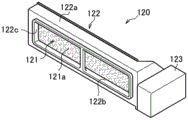
Fig. 7 is a perspective view showing a damper member for cooling the upper switching chamber to a freezing temperature zone.
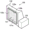
Fig. 8 is a perspective view showing a damper member for cooling the lower stage switching chamber to a freezing temperature zone.
Fig. 9 is a perspective view showing a damper member for cooling the upper stage switching chamber and the lower stage switching chamber to a refrigerating temperature zone.
FIG. 10 is a top view showing the back side of the damper component of FIG. 9.
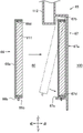
Fig. 11 is a sectional view showing the configuration of the damper component.
Fig. 12 is a schematic view illustrating the flow of cold air in the whole refrigerator according to the first embodiment.
Fig. 13 (a) is a sectional view showing a refrigerator including a centrifugal fan as a first embodiment, and (b) is a sectional view showing a refrigerator including a propeller fan as a comparative example.
Fig. 14 is an exploded perspective view showing the heat insulating partition member.
Fig. 15 is a sectional view showing an installation state of the heat insulating partition member.
Fig. 16 is a cross-sectional view showing a modification of the heat insulating partition member.
Fig. 17 is a sectional view showing the rear heat insulating partition member.
Fig. 18 is a sectional view showing the arrangement of the heater of the switching chamber.
Fig. 19 is a plan view showing the arrangement of the heaters of the rear heat insulating partition member.
Fig. 20 is a sectional view showing the arrangement of the blower fan and the heater of the fan housing.
Fig. 21 is a cross-sectional view showing a modification of the arrangement of the heater of the blower fan.
Fig. 22 is a diagram showing an operation panel for switching the temperature zone.
Fig. 23 is a diagram showing a modification of the arrangement of the operation panel.
Fig. 24 is a diagram showing a confirmation mechanism of the temperature zone.
Fig. 25 is a schematic diagram showing a reporting mechanism of the temperature zone.
Fig. 26 is a sectional view showing a refrigerator of the second embodiment.
Fig. 27 is a sectional view showing a refrigerator of a third embodiment.
Fig. 28 is a sectional view showing a refrigerator of the fourth embodiment.
In the figure:
1. 1A, 1B, 1C-refrigerator, 10-refrigerator body, 11-inner box, 11e, 11 g-rib, 12-outer box, 16, 17-heat insulating partition member, 30-refrigerating chamber, 40-ice making chamber (storage chamber), 50-freezing chamber (storage chamber), 60-upper layer switching chamber (switching chamber), 61-upper layer storage container (storage container), 62-lower layer storage container (storage container), 63a, 63B-ejection port (ejection port for freezing temperature zone), 63C-ejection port (ejection port for refrigerating temperature zone), 64-storage container (storage container for freezing temperature zone), 65-back heat insulating partition member, 66-storage panel, 67-holding panel, 68 a-light emitting section (first light emitting section), 68B-light emitting section (second light emitting section), 70-lower layer switching chamber (switching chamber), 71-upper layer storage container (storage container), 72-lower storage container (storage container), 73a, 73 b-ejection port (ejection port for freezing temperature zone), 73 c-ejection port (ejection port for freezing temperature zone), 74-storage container (storage container for freezing temperature zone), 78 a-light emitting portion (first light emitting portion), 78 b-light emitting portion (second light emitting portion), 80A-cooler, 90-blower fan, 100-cooler storage space, 111-fan housing, 111 s-opening, 120-damper member (damper for freezing temperature zone, damper for upper switching chamber), 121-damper plate (vane member), 121 a-seal member, 122-damper plate support portion, 122 a-valve body, 122 b-opening, 122 c-valve seat portion, 123-drive portion, 130-damper member (damper for freezing temperature zone, damper for lower switching chamber), 140-damper member (damper for freezing temperature zone), 141-damper part (damper for upper switching chamber), 142-damper part (damper for lower switching chamber), 143-drive part, 143 a-female connector part, 143 b-terminal part, 150-control panel (operation panel), 160-housing, 161-lower housing, 162-upper housing, 164-seal, H1-H11-heater, P1-outer peripheral end, P2-front end, V1-V11-vacuum insulation material.
Detailed Description
Hereinafter, a mode for carrying out the present invention (present embodiment) will be described. However, the present embodiment is not limited to the following, and can be modified and implemented as desired within a range not to impair the gist of the present invention. Hereinafter, the description will be made with reference to the direction shown in fig. 1.
(first embodiment)
Fig. 1 is an external perspective view showing a refrigerator of a first embodiment. In the following, a six-door refrigerator 1 will be described as an example, but the present invention can also be applied to a refrigerator having five doors or less and seven doors or more.
As shown in fig. 1, the refrigerator 1 includes a refrigerator main body 10, and the refrigerator main body 10 includes a refrigerating compartment 30, an ice making compartment 40, a freezing compartment 50, an upper switching compartment 60 (switching compartment), and a lower switching compartment 70 (switching compartment). The upper switching chamber 60 can switch the temperature band from a refrigerating temperature band (for example, 1 ℃ to 6 ℃) to a freezing temperature band (for example, about-20 ℃ to-18 ℃). The lower layer switching chamber 70 is also the same, and can switch the temperature band from the refrigerating temperature band to the freezing temperature band. The refrigerating compartment 30 is set to a refrigerating temperature zone (e.g., 6 deg.c), and the ice-making compartment 40 and the freezing compartment 50 are set to a freezing temperature zone (e.g., about-20 deg.c).
The refrigerating chamber doors 2 and 3 are configured to be openable. The ice making chamber door 4, the freezing chamber door 5, the upper switching chamber door 6, and the lower switching chamber door 7 are configured to be able to be drawn out in a forward direction. The refrigerating compartment doors 2, 3, the ice making compartment door 4, the freezing compartment door 5, the upper switching compartment door 6, and the lower switching compartment door 7 are heat-insulated doors.
Fig. 2 is a longitudinal sectional view showing the inside of the refrigerator of the first embodiment.
As shown in fig. 2, the refrigerator main body 10 is formed by combining an inner box 11 and an outer box 12, and a foam heat insulating material and a vacuum heat insulating material are interposed therebetween to form a heat insulating box body. The thermal insulating foamed material is formed of rigid polyurethane foam. The rigid polyurethane foam is formed by foaming and then curing a polyurethane foam stock solution (a stock solution for a foamed heat insulating material). That is, examples of the polyurethane foam raw liquid include a liquid obtained by mixing a solution obtained by premixing a blowing agent such as cyclopentane or water, and an auxiliary agent such as a catalyst or a foam stabilizer with a polyether polyol, and an isocyanate solution.
The outer box 12 includes a top plate 1a formed by bending a thin steel plate into a door shape, left and right side plates 1b and 1c (see fig. 1), a back plate 1d formed of different members, and a bottom plate 1e formed of different members. A recess is provided in the top plate 1a at the rear, and a control board 13 is provided in the recess. The control substrate 13 collectively controls the refrigerator 1.
Vacuum heat insulating materials V1 and V2 are provided on the inner wall surfaces of the top plate 1a and the back plate 1 d. A vacuum insulation material V3 is provided on the bottom surface side of the inner box 11. Vacuum heat insulating materials V7, V8 (see fig. 3) are provided on the inner wall surfaces of the left and right side plates 1b, 1c (see fig. 1).
The refrigerating chamber doors 2 and 3 are provided with vacuum heat insulating materials V4. The upper switching chamber door 6 is provided with a vacuum insulation material V5. A vacuum insulation material V6 is provided on the lower layer switching chamber door 7.
Refrigerator main body 10 includes heat insulating partition member 15 for vertically and thermally partitioning refrigerating compartment 30, ice making compartment 40, and freezing compartment 50. The refrigerator main body 10 includes a heat insulating partition member 16 that thermally partitions the ice making chamber 40, the freezing chamber 50, and the upper switching chamber 60. The refrigerator main body 10 includes a heat insulating partition member 17 for dividing the upper stage switching chamber 60 and the lower stage switching chamber 70 into heat insulation. Vacuum heat insulating materials V9 and V10 are provided in the heat insulating partition members 16 and 17, respectively.
In order to cool each of the ice making compartment 40, the freezing compartment 50, the upper stage switching compartment 60, and the lower stage switching compartment 70 to a predetermined temperature, a cooler 80A (EVP: evaporator) is provided on the back side of the upper stage switching compartment 60 and the lower stage switching compartment 70 of the refrigerator 1. The cooler 80A constitutes a refrigeration cycle by a compressor 81, a condenser (not shown), and a capillary tube (not shown). Above cooler 80A, air blowing fan 90 is disposed to circulate the cold air cooled by cooler 80A to each of ice making compartment 40, freezing compartment 50, upper layer switching compartment 60, and lower layer switching compartment 70 to maintain a predetermined temperature.
The cooler 80A is disposed in the cooler storage space 100, and the cooler storage space 100 is provided between the inner box 11 and the back surfaces of the ice making compartment 40, the freezing compartment 50, the upper stage switching compartment 60, and the lower stage switching compartment 70. The cooler accommodating space 100 extends from a position right above the compressor 81 provided in the machine chamber Q to a height position of the blower fan 90.
A defrosting heater 82 is provided below the cooler 80A in the cooler housing space 100. The drain water generated during defrosting by the defrosting heater 82 temporarily flows down the downpipe (water conduit) 83, and is accumulated in an evaporation tray (not shown) provided above the compressor 81 through a drain hole (not shown).
The air (cold air) cooled by the cooler 80A is directly supplied to the ice making chamber 40 and the freezing chamber 50 without passing through the damper member. The upper switching chamber 60 is supplied with cold air through a damper member 120 for direct cooling and a damper portion 141 (see fig. 4) of a damper member 140 for indirect cooling, which will be described later. Cold air is supplied to the lower stage switching chamber 70 through a damper member 130 for direct cooling (see fig. 4) and a damper portion 142 of a damper member 140 for indirect cooling (see fig. 4), which will be described later. Direct cooling is a method of directly supplying cold air to the stored food to cool the food. The indirect cooling is a cooling method in which cold air is supplied so as not to directly contact with the stored food in order to suppress drying of the food.
In refrigerator 1, cooler 80B is provided at a lower portion of the rear side of refrigerating compartment 30 in order to cool refrigerating compartment 30 to a predetermined temperature. The cooler 80B constitutes a refrigeration cycle by a compressor 81, a condenser (not shown), and a capillary tube (not shown). A blower fan (not shown) for circulating the cold air cooled by cooler 80B to refrigerating compartment 30 to maintain a predetermined temperature is provided above cooler 80B.
For example, an upper storage container 61 and a lower storage container 62 are disposed vertically in the upper switching chamber 60. For example, an upper storage container 71 and a lower storage container 72 are disposed vertically in the lower switching chamber 70. The number of the storage containers 61, 62, 71, and 72 is not limited to the present embodiment, and may be changed as appropriate, and may be one layer or three or more layers.
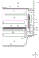
Fig. 3 is a front view showing the inside of the cabinet of the refrigerator main body. Fig. 3 schematically shows a state where the doors 2 to 7, the storage container, and the like are removed from the refrigerator 1.
As shown in fig. 3, the refrigerator main body 10 includes a rear heat insulating partition member 65 that constitutes the rear surfaces of the upper stage switching chamber 60 and the lower stage switching chamber 70. The lower end of the rear heat insulating partition member 65 is positioned above the inward projection of the machine chamber Q (see fig. 2).
The discharge port 63a is formed at a position where cold air can be directly supplied into the upper layer storage container 61 (see fig. 2). Further, discharge port 63b is formed at a position where cold air can be directly supplied into lower storage container 62 (see fig. 2).
At least a part of vacuum heat insulating material V11 (see fig. 2) is present in the rear projection of case member 112. This can increase the area of the vacuum insulation material V11 to ensure high insulation performance, and can also ensure the width of the air blowing duct inside the casing member 112, thereby suppressing a reduction in ventilation resistance.
The material of the vacuum insulation materials V1 to V11 is not particularly limited, and examples thereof include an insulation material in which a core material such as a porous glass wool is vacuum-packed with a laminate film and the interior is sealed by reducing the pressure. Since the gas thermal conductivity is substantially zero, it has excellent thermal insulation properties.
A return port 73d for returning the cold air discharged from discharge ports 73a, 73b, and 73c to cooler 80A (see fig. 2) is formed in rear surface heat insulating partition member 65. The return port 73d is formed on the opposite side (right side in fig. 3) of the discharge port 73c with the discharge port 73a interposed therebetween.
Further, ejection ports 40a and 50a for directly supplying cold air into the ice making container (not shown) and the freezing container (not shown) are formed in ice making chamber 40 and freezing chamber 50, respectively. A return port 41a for returning the cold air discharged from discharge ports 40a and 50a is formed in the rear surface of freezing chamber 50.
Fig. 4 is a view of the cool air duct as viewed from the back. Fig. 4 schematically shows a state where the inner case 11 is removed and viewed from the rear.
As shown in fig. 4, an air supply fan 90 is provided above the cooler 80A. The blower fan 90 is a centrifugal fan such as a turbo fan or a sirocco fan.
A fan case 111 that houses the blower fan 90 is provided above the cooler housing space 100. A circular opening 111s is formed in the fan casing 111 at a position facing the blower fan 90. The air-sending fan 90 sucks in the cold air through the opening 111s and discharges the cold air from the circumferential direction into the fan casing 111.
Returning to fig. 3, the case member 112 is disposed so as to cover the front of the damper member 120 (see fig. 2), and is formed so as to protrude forward from the rear heat insulating partition member 65. The case member 113 is disposed so as to cover the front of the damper section 141 (see fig. 4), and is formed to protrude forward from the rear heat insulating partition member 65.
The case member 114 is formed to cover the front of the damper member 130 (see fig. 4) and to protrude forward from the rear heat insulating partition member 65. The case member 115 communicates with the flow path 116 extending from the damper section 142, and is formed to protrude forward from the rear heat insulating partition member 65.
As shown in fig. 4, the cooler storage space 100 is formed with a return flow path 41b that merges the cold air blown out from the return port 41a and the cold air blown out from the return port 73 d. The return flow path 41b is configured to flow in the vertical direction on the right side (left side in fig. 4) of the rear heat insulating partition member 65.
The cold air discharged from discharge ports 63a and 63b (see fig. 3) flows downward of cooler 80A through return port 63d, rises in cooler 80A, and is then again sucked into air blowing fan 90. Similarly, the cold air discharged from discharge port 63c (see fig. 3) passes through cooler 80A from return port 63d, and is then again sucked into blower fan 90.
The cold air discharged from discharge ports 73a and 73b (see fig. 3) is returned to the lower side of cooler 80A from return port 73d, rises in cooler 80A, and is then sucked into air blowing fan 90 again. Similarly, the cold air discharged from discharge port 73c (see fig. 3) returns to return port 73d and passes through cooler 80A, and is then again sucked into blower fan 90.
Further, the cold air having cooled the ice-making chamber 40 and the freezing compartment 50 passes through the return flow path 41b from the return port 41a, passes through the same flow path as the return flow path from the return port 73d, and then returns to the cooler 80A.
Fig. 5 is a diagram showing a fan housing.
As shown in fig. 5, the fan case 111 includes a flow path 111a for guiding the cold air toward the shutter member 120 and a flow path 111b for guiding the cold air toward the shutter member 130. The fan case 111 includes a flow path 111c for guiding the cold air toward the damper portion 141 of the damper member 140, and a flow path 111d for guiding the cold air toward the damper portion 142 of the damper member 140.
A damper member 120 is fitted to an end of the flow path 111a via a seal not shown. A damper member 130 is fitted to an end of the flow path 111b via a seal not shown. A damper portion 141 is fitted to an end of the flow path 111c via a seal not shown. A damper portion 142 is fitted to an end of the flow passage 111d via a seal not shown.
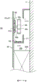
Fig. 6 is a sectional view taken along line a-a of fig. 4. In fig. 6, the outer box 12, the insulating material between the inner box 11 and the outer box 12, the doors 4, 6, and 7, and the storage containers 61, 62, 71, and 72 are not shown.
As shown in fig. 6, the refrigerator main body 10 includes a heat insulating partition member 16 that insulates the ice making chamber 40 and the freezing chamber 50 (see fig. 3) from the upper switching chamber 60. The refrigerator main body 10 is provided with a heat insulating partition member 17 for insulating the upper stage switching chamber 60 from the lower stage switching chamber 70. The refrigerator main body 10 includes a rear heat-insulating partition member 65 that insulates the upper switching chamber 60 from the blower fan 90 and the cooler 80A.
The blower fan 90 is fixed to the rear heat insulating partition member 65 via a bracket 92. The attachment mechanism of the blower fan 90 is not limited to the mechanism fixed to the rear heat insulating partition member 65, and may be fixed by providing a bracket on the cold air intake side of the fan casing 111.
The heat insulating partition members 16 and 17 are each configured to include vacuum heat insulating materials V9 and V10. The rear heat insulating partition member 65 is configured to include a vacuum heat insulating material V11.
As described above, the vacuum heat insulators V7 and V8 are provided on the left and right side surfaces of the upper switching chamber 60 of the refrigerator main body 10 (see fig. 3). As described above, the vacuum insulation material V5 (see fig. 2) is also provided on the upper switching chamber door 6 for opening and closing the upper switching chamber 60. Thus, the upper switching chamber 60 is surrounded on its front, rear, right, left, and upper and lower six sides by vacuum insulation materials V5, V7, V8, V9, V10, and V11. In this way, ice making compartment 40 and freezing compartment 50 are set to the freezing temperature zone, and cooler 80A is disposed on the rear surface, and in this case, even when the conditions when upper layer switching compartment 60 is set to the refrigerating temperature zone are severe, upper layer switching compartment 60 can be set to the refrigerating temperature zone.
Further, in the refrigerator main body 10, an opening 63e communicating with a return port 63d returning to the cooler 80A is formed on the rear side of the heat insulating partition member 17 constituting the bottom surface of the upper stage switching chamber 60. The opening 63e is formed to be elongated in the left-right direction.
A rail member 11a that slidably supports an upper storage container 61 (see fig. 2) in the front-rear direction is formed on the left side surface of the upper switching chamber 60 of the refrigerator main body 10. The upper switching chamber door 6 (see fig. 2) is provided with a slide member (not shown) for holding the lower storage container 62 (see fig. 2), and the slide member is slidably supported by the rail member 11b provided in the upper switching chamber 60. Further, a rail member having the same structure is provided on the right side surface of the upper stage switching chamber 60.
A rail member 11c that slidably supports the upper storage container 71 (see fig. 2) in the front-rear direction is formed on the left side surface of the lower switching chamber 70 of the refrigerator main body 10. The lower switching chamber door 7 (see fig. 2) is provided with a slide member (not shown) for holding the lower storage container 72 (see fig. 2), and the slide member is slidably supported by the rail member 11d provided in the lower switching chamber 70. Further, a rail member having the same structure is also provided on the right side surface of the lower stage switching chamber 70.
Fig. 7 is a perspective view showing a damper member for cooling the upper stage switching chamber to a freezing temperature zone, fig. 8 is a perspective view showing a damper member for cooling the lower stage switching chamber to a freezing temperature zone, fig. 9 is a perspective view showing a damper member for cooling the upper stage switching chamber and the lower stage switching chamber to a refrigerating temperature zone, and fig. 10 is a plan view showing a back side of fig. 9.
As shown in fig. 7, the damper member 120 (the damper for the freezing temperature zone) includes an insert plate support portion 122 that openably supports an insert plate 121 (a blade member), and a drive portion 123 that applies a rotational drive force to the insert plate 121. The driving unit 123 opens and closes the board 121 by a known technique including a motor and a gear.
The insert plate support portion 122 has a valve body 122a formed to be elongated in the lateral direction (width direction), and a rectangular opening 122b formed in the front surface of the valve body 122 a. An annular valve seat portion 122c extending from the opening 122b toward the back side is formed in the opening 122 b.
A sheet-like sealing material 121a is attached to the entire front side of the insert plate 121. The peripheral edge portion of the front surface of insert plate 121 abuts valve seat portion 122c, so that the cold air does not leak from opening 122 b.
As shown in fig. 8, the damper member 130 (the damper for the freezing temperature zone) includes an insert plate support portion 132 that openably supports an insert plate 131 (a blade member), and a drive portion 133 that applies a rotational drive force to the insert plate 131.
The insert plate support portion 132 has a valve body 132a formed substantially in a square shape, and a square opening 132b formed in the front surface of the valve body 132 a. An annular seat portion 132c extending from the opening 132b toward the back side is formed in the opening 132 b.
A sheet-like sealing material 131a is attached to the entire front side of the insert plate 131. The peripheral edge portion of the front surface of the insert plate 131 abuts on the valve seat portion 132c, so that the cold air does not leak from the opening 132 b.
As shown in fig. 9, the damper component 140 has a driving portion 143 between the damper portion 141 and the damper portion 142. The damper parts 141 and 142 include the inlet plates 141a and 142a and the inlet plate support parts 141b and 142b, as in the damper members 120 and 130. The insert plate support portions 141b and 142b include valve bodies 141c and 142c, opening portions 141d and 142d, and seat portions 141e and 142 e. Sealing materials 141f and 142f are bonded to the entire front sides of the inserts 141a and 142 a.
The driving unit 143 includes a single motor, and the gate 141 and 142 can be independently opened and closed by a known technique. That is, the shutter member 140 is configured to be able to close both the shutter portions 141, 142 and to open both the shutter portions 141, 142. The shutter member 140 is configured to be able to open the shutter portion 141 and close the shutter portion 142, and to be able to close the shutter portion 141 and open the shutter portion 142. In this way, the damper member 140 is formed by concentrating the damper sections 141 and 142, thereby reducing the manufacturing cost. In the present embodiment, the case where the damper portions 141 and 142 are integrally formed has been described as an example, but the damper portions 141 and 142 may be separately formed.
As shown in fig. 10, the back sides of the damper portions 141, 142 of the damper component 140 are shaped such that the peripheries of the insert plates 141a, 142a are open toward the back side. That is, the insert plate support portions 141b and 142b have valve bodies 141c and 142c having a shape that opens rearward. A groove-like slit is formed between the valve elements 141c, 142c and the seat portions 141e, 142e (see fig. 9), in other words, slits S1, S2 are formed around the insert plates 141a, 142 a.
Similarly to the damper component 140, the damper components 120 and 130 are also shaped so as to open toward the back side and have slits formed around the insert plates 121 and 131.
The insert plate 141a has a rotating shaft 141g and is rotatably supported inside the valve body 141 c. The insert plate 142a has a rotating shaft 142g and is rotatably supported inside the valve body 142 c. The rotating shafts 141g and 142g are arranged in parallel with each other in the axial direction and are formed at positions not overlapping each other in the axial direction. The insert plates 141a and 142a are configured to open in opposite directions to each other in a direction orthogonal to the axial direction.
A female connector portion 143a for control is provided on the back side of the housing of the driving portion 143. The terminal portion 143b of the female connector portion 143a is formed to extend toward the door portion 142 side, and a male connector (not shown) is inserted into the female connector portion 143a from below in the vertical direction to perform electrical connection. The shutter member 140 is disposed such that the shutter portion 141 is positioned above the fan case 111 (see fig. 4) in the vertical direction, the shutter portion 142 is positioned below, and the female connector portion 143a is positioned downward. Therefore, even if drain water produced when frost generated in the damper member 140 melts flows down on the housing of the driving portion 143, the terminal portion 143b can be prevented from being exposed to the drain water.
Fig. 11 is a sectional view showing the configuration of the damper component.
In the damper member 120, in the arrangement shown in fig. 11 (a), water W is likely to accumulate on the inner wall surface of the lower portion of the valve body 122a of the insert plate supporting portion 122. If the water W freezes at such a position, the insert plate 121 may be caught by ice and may not be opened. Therefore, as shown in fig. 11 (b), by inclining the shutter member 120 so that the valve body 122a is lowered toward the rear side, the water W can be prevented from accumulating on the back side of the insert plate support portion 122. The damper members 130 and 140 are also similarly disposed obliquely.
When the shutter member 120 is disposed as shown in fig. 11 (b), water accumulates in the recess formed by the valve seat portion 122c and the insert plate 121. However, since the heater H6 (see fig. 19) described later is provided in the damper member 120, the water flows to the rear side by opening the insert plate 121.
The resin material of the damper member 120 may be made of a resin having a hydrophobic property or a resin having a hydrophilic property.
Fig. 12 is a schematic view illustrating the flow of cold air of the refrigerator of the present embodiment.
As shown in fig. 12, in refrigerating room 30 of refrigerator 1, cold air generated by cooler 80B dedicated to refrigerating room 30 is sucked into air blowing fan 91 and is discharged from a plurality of discharge ports (not shown) provided on the rear surface in refrigerating room 30. The cold air having cooled the food is returned to cooler 80B through a return port (not shown) provided in the lower portion of refrigerating compartment 30.
In the ice making chamber 40 and the freezing chamber 50 of the refrigerator 1, the cool air generated by the cooler 80A is blown out by the blower fan 90 from the discharge port 40A (see fig. 3) provided in the ice making chamber 40 and the discharge port 50A (see fig. 3) provided in the freezing chamber 50. The air having cooled the food is sucked into return port 41 provided on the back surface side of freezer compartment 50, and is returned to cooler 80A through return flow path 41 b. In this way, in the ice making compartment 40 and the freezing compartment 50, the cold air generated by the transport cooler 80A is always supplied.
When the upper switching chamber 60 is set to the freezing temperature zone, the damper member 120 is opened. In this case, the cold air generated by the cooler 80A passes through the damper member 120. The cold air is supplied directly from the discharge port 63a provided in the upper switching chamber 60 to the food in the upper storage container 61, and is supplied directly from the discharge port 63b to the food in the lower storage container 62.
When the upper stage switching chamber 60 is set to the cooling temperature range, the damper portion 141 of the damper member 140 is opened. In this case, the cold air generated by the cooler 80A passes through the damper portion 141. The cold air flows from the discharge port 63c provided in the upper switching chamber 60 to the outside of the upper storage container 61 and the outside of the lower storage container 62, thereby indirectly cooling the food. This can suppress drying of the food in the upper storage container 61 and the lower storage container 62.
When the lower layer switching chamber 70 is set to the freezing temperature zone, the cold air generated by the cooler 80A passes through the damper member 130. The food in the upper storage container 71 is directly supplied from the discharge port 73a provided in the lower switching chamber 70, and the food in the lower storage container 72 is directly supplied from the discharge port 73 b.
When the lower layer switching chamber 70 is set to the refrigerating temperature zone, the damper portion 142 of the damper member 140 is opened. In this case, the cold air generated by the cooler 80A passes through the damper portion 142 and the flow path 116 (see fig. 4). The cold air flows from discharge port 73c provided in lower switching chamber 70 to the outside of upper storage container 71 and the outside of lower storage container 72, thereby indirectly cooling the food. This can suppress drying of the food in the upper storage container 71 and the lower storage container 72.
In this way, in the refrigerator 1 of the first embodiment, the upper stage switching chamber 60 can be set to the refrigerating temperature zone and the lower stage switching chamber 70 can be set to the freezing temperature zone. In the refrigerator 1, the upper stage switching chamber 60 can be set to a freezing temperature zone and the lower stage switching chamber 70 can be set to a refrigerating temperature zone. In the refrigerator 1, both the upper stage switching chamber 60 and the lower stage switching chamber 70 can be set to the freezing temperature zone. In the refrigerator 1, both the upper stage switching chamber 60 and the lower stage switching chamber 70 can be set to the refrigerating temperature zone.
Fig. 13 (a) is a sectional view showing a refrigerator including a centrifugal fan as a blower fan according to the first embodiment, and fig. 13 (b) is a sectional view showing a refrigerator including a propeller fan as a blower fan according to a comparative example.
As shown in fig. 13 (a), the refrigerator 1 includes a centrifugal fan (turbo fan, sirocco fan) as the air blowing fan 90, and the air blowing fan 90 is disposed behind the rear heat insulating partition member 65. Such a blower fan 90 sucks in cold air from the center side in the radial direction and discharges the cold air in the circumferential direction, thereby reducing the space in the axial direction forward of the blower fan 90 and securing the space in the axial direction rearward (suction side). Therefore, in the first embodiment, the dimension D1 in the front-rear direction of the cooler accommodating space 100 provided on the rear side of the upper stage switching chamber 60 can be reduced.
In contrast, the refrigerator 200 shown as a comparative example in fig. 13 (b) includes a propeller fan as the blower fan 201, and the blower fan 201 is disposed behind the rear heat insulating partition member 202. In such a case, the blower fan 201 is disposed obliquely, and needs a suction space and a discharge space at the rear and the front, respectively. Therefore, it is necessary to ensure a large space of the cooling flow path provided on the rear surface side of the upper switching chamber 203 by the dimension D100 (> D1) in the front-rear direction.
In this way, in the first embodiment, the volume Q1 of the upper stage switching chamber 60 in the case of the blower fan 90 can be ensured to be larger than the volume Q100 of the upper stage switching chamber 203 in the case of the blower fan 201 as a comparative example. This can increase the amount of food stored in the upper layer switching chamber 60.
Further, by dividing cooler 80B for refrigerating room 30 and cooler 80A on the lower side of refrigerating room 30, cooler 80A can be made small (for example, seven layers → five layers). This makes it possible to reduce the size of the cooler accommodating space 100 in the vertical direction. Therefore, the volume of the back surface of ice making chamber 40 and freezing chamber 50 protruding forward can be reduced, and the volume of ice making chamber 40 and freezing chamber 50 can be increased.
Further, an air supply fan 90 is provided in a top projection of the cooler 80A, and at least a part of a damper member 120 (see fig. 6) is provided in a top projection of the air supply fan 90. The axial direction of the blower fan 90 is substantially parallel to the front-rear direction of the opening 122b of the damper member 120. Therefore, the cold air sent in the centrifugal direction from the air sending fan 90 hits the shutter member 120 in the open state of the shutter member 121, and is then sent to the upper switching chamber 60 located on the front side of the opening 122 b. The support portion 92b of the blower fan 90 or the surface of the holding panel 67 facing the support portion 92b (see fig. 20), the front surface portion of the damper member 120 where the opening 122b is provided, and the vacuum insulation material V11 or the holding panel 67 facing the rear surface portion of the vacuum insulation material V11 are arranged substantially in parallel. This makes it possible to make the cooler housing space 100 and the air duct for guiding the air blown by the air blowing fan 90 compact in size in the front-rear direction, and to ensure a large capacity of the upper stage switching chamber 60.
Fig. 14 is an exploded perspective view showing the heat insulating partition member.
As shown in fig. 14, the heat insulating partition member 16 includes a synthetic resin case 160 composed of a lower case 161 and an upper case 162, expanded polystyrene (so-called expanded styrene) 163 as a heat insulating material, and a vacuum heat insulating material V9 as another heat insulating material. Since the heat insulating and partitioning member 17 has the same structure as the heat insulating and partitioning member 16, only the heat insulating and partitioning member 16 will be described below.
The lower case 161 is formed in a rectangular parallelepiped shape, and has an upright side surface portion 161a at an outer peripheral edge portion. The side surface 161a is formed on the whole four sides. The lower case 161 is formed with locking claws 161b, 161b on the side of the side surface portion 161a facing the outer surface.
The upper case 162 is formed in a rectangular parallelepiped shape, and an outer peripheral edge portion has a side surface portion 162a extending toward the lower case 161. The side surface 162a is formed on the entire four sides. The upper case 162 is formed with a locking hole 162b that engages with the locking claw 161b at a side of the side surface portion 162a facing the outer surface.
The expanded polystyrene 163 has a rectangular shape fitted into the lower case 161. The expanded polystyrene 163 is formed to have a thickness lower than the height of the side surface 161 a.
The vacuum insulation material V9 is configured in the same manner as the vacuum insulation materials V1 to V8 described above, and is formed in a rectangular shape to be accommodated in the lower case 161. When the vacuum insulation material V9 is accommodated in the lower case 161 together with the expanded polystyrene 163, the surface of the vacuum insulation material V9 is set to have a thickness at the upper end of the side surface portion 161 a.
A sealing material 164 is bonded to a side surface of the vacuum insulation material V9. The seal 164 is formed on the entire outer peripheral surface of the vacuum insulation material V9. By providing the seal 164, the gap between the lower case 161 and the outer peripheral surface of the vacuum insulation material V9 can be filled, and the vacuum insulation material V9 can be prevented from moving in the lower case 161 and being damaged.
In the heat insulating partition member 16, the lower case 161 accommodates the expanded polystyrene 163 and the vacuum heat insulating material V9, and then covers the upper case 162. In this case, the side surface portion 162a of the upper case 162 is located outside the side surface portion 161a of the lower case 161. Therefore, when the upper case 162 is covered on the lower case 161, the side surface portion 162a does not contact the vacuum heat insulating material V9, and the vacuum heat insulating material V9 can be prevented from being damaged.
A double-sided tape 162c is provided on the inner surface of the upper case 162. By bonding the upper case 162 and the vacuum insulation material V9 with the double-sided tape 162c, the upper case 162 can be prevented from being peeled off from the lower case 161. Further, the double-sided tape 162c can prevent a gap (space) from being formed between the upper case 162 and the vacuum insulation material V9, and can prevent frost and dew from being generated in the gap.
In the present embodiment, a case where the lower case 161 and the upper case 162 are fixed by fitting the locking claws 161b into the locking holes 162b has been described as an example. However, the structure is not limited to this, and the lower case 161 and the upper case 162 may be screwed.
Fig. 15 is a sectional view showing an installation state of the heat insulating partition member.
As shown in fig. 15, in the case where the heat insulating partition member 16 is installed, a partition wall 18 that partitions the ice making compartment 40 and the freezing compartment 50 into left and right is provided on the upper side of the heat insulating partition member 16. Therefore, the heat insulating partition member 16 is attached from below the partition wall 18, and the heat insulating partition member 16 cannot be attached from above.
However, in manufacturing, the outer dimensions of the vacuum insulation material V9 are likely to vary, and the largest vacuum insulation material differs from the smallest vacuum insulation material. Due to the size of such a difference, heat insulation is not possible, and in this case, frost may be generated at the end of the switching chamber (in the case of a cold storage temperature zone chamber). Therefore, the front end portion P2 of the polyurethane (rigid polyurethane foam) of the rib 11e is located inward (inward) in the left-right direction (width direction) compared to the position (outer peripheral end portion P1) where the vacuum insulation material V9 is the smallest size. In other words, the end of the vacuum insulation material V9 and the rib 11e filled with urethane are arranged to overlap in the vertical direction. By providing such a configuration, it is possible to suppress the risk of non-heat insulation between the upper stage switching chamber 60 and the ice making chamber 40 at the left end and between the upper stage switching chamber 60 and the freezing chamber 50 at the right end.
When the heat insulating partition member 17 that partitions the upper switching chamber 60 and the lower switching chamber 70 is attached, only the upper switching chamber 60 is present above the heat insulating partition member 17. Therefore, the heat insulating partition member 17 can be attached from the upper side opposite to the heat insulating partition member 16. The heat insulating partition member 17 is fixed to ribs 11g formed on the left and right side surfaces of the inner box 11.
Similarly, the heat insulating partition member 17 has the front end P2 of the polyurethane (rigid polyurethane foam) of the rib 11g positioned inward (inward) in the lateral direction (width direction) as compared with the position (outer peripheral end P1) of the smallest dimension of the vacuum heat insulating material V10 (see fig. 2). In other words, the end of the vacuum insulation material V10 and the rib 11g filled with urethane are arranged to overlap in the vertical direction. By adopting such a configuration, the risk of thermal insulation failure between the upper-stage switching chamber 60 and the lower-stage switching chamber 70 can be suppressed.
Further, a gap (not shown) is provided between the inner box 11 and at least one of the left and right end portions of the heat insulating partition member 16 and the heat insulating partition member 17. The foamed heat insulating material is filled between the inner box 11 and the outer box 12, and in the manufacturing process, the outer dimensions are likely to vary, and for example, the inner box 11 may be deformed so as to expand toward the inside of the box. On the other hand, the heat insulating partition member 16 and the heat insulating partition member 17 are not filled with a thermal insulating foamed material therein, and variations in outer dimensions in manufacturing are less likely to occur. Therefore, in consideration of the ease of assembling the heat insulating partition member 16 and the heat insulating partition member 17 at a predetermined position of the inner box 11, it is desirable to provide a gap for absorbing dimensional tolerance generated after foaming of the thermal insulating foamed material inside the inner box 11. In this case, a seal (not shown) having elasticity may be interposed at least in a part of the gap, and the gap may be filled with the seal, whereby the influence of the thermal bridge can be suppressed.
Fig. 16 is a sectional view showing a modification of the partition heat-insulating wall. Note that the same components as those of the heat insulating and partitioning members 16 and 17 shown in fig. 15 are denoted by the same reference numerals, and redundant description thereof is omitted.
As shown in fig. 16, the heat insulating partition members 16 and 17 include expanded polystyrene (expanded styrene) 163a provided below the vacuum heat insulating materials V9 and V10, and expanded polystyrene (expanded styrene) 163b provided above the vacuum heat insulating materials V9 and V10. Thus, the entire periphery of the vacuum insulation materials V9 and V10 is covered with the expanded polystyrene 163a and 163 b. Since the entire vacuum insulation materials V9 and V10 are covered with such a structure, damage to the vacuum insulation materials V9 and V10 can be more reliably suppressed, and the seal 164 used in the above-described embodiment can be eliminated. The same applies to the left and right end portions of the heat insulating partition members 16 and 17, and the same arrangement as that in fig. 15 can suppress the risk of heat non-insulation.
Fig. 17 is a sectional view showing the rear heat insulating partition member.
As shown in fig. 17, the rear heat-insulating partition member 65 is configured to include a vacuum heat-insulating material V11, a storage panel 66 that stores the vacuum heat-insulating material V11, and a holding panel 67 that holds the storage panel 66. In the present embodiment, the housing is configured by the housing panel 66 and the holding panel 67.
The receiving panel 66 has a bottom surface 66a which one surface of the vacuum insulation material V11 contacts, and a side surface 66b which stands from the bottom surface 66 a. A locking claw 66c is formed to protrude from an outer surface of the side surface 66 b. Further, a seal 66d is provided on the outer peripheral surface of the vacuum insulation material V11. Thus, the gap between the outer peripheral surface of the vacuum insulation material V11 and the side surface 66b is filled, and the vacuum insulation material V11 can be prevented from moving in the storage panel 66 and damaging the vacuum insulation material V11.
The holding panel 67 includes a partition plate 67a that partitions the upper stage switching chamber 60 and the cooler storage space 100, an upper holding portion 67b that holds the upper portion of the storage panel 66, and a lower holding portion 67c that holds the lower portion of the storage panel 66. The upper holding portion 67b is formed in a concave shape so that the concave surface is opened downward. The lower holding portion 67c is formed with a locking hole 67d to which the locking claw 66c is locked.
When the storage panel 66 storing the vacuum insulation material V11 is attached, the vacuum insulation material V11 is attached in a state where the exposed surface faces the holding panel 67 side. In this case, the upper portion of the storage panel 66 is inserted into the upper holding portion 67b, and the storage panel 66 is rotated toward the partition plate 67a with the upper portion as a fulcrum. Then, the accommodation panel 66 is pressed against the partition plate 67a, and the locking claws 66c of the accommodation panel 66 are fitted into the locking holes 67d, whereby the accommodation panel 66 is held by the holding panel 67. In this way, by configuring the upper holding portion 67b to cover the upper portion of the storage panel 66, even if water flows down from the upper portion of the storage panel 66, it is possible to prevent water from entering the storage panel 66. When the receiving panel 66 is attached to the holding panel 67, the lower holding portion 67c is positioned outside the side surface 66b, and damage to the vacuum insulation material V11 can be prevented.
However, when the upper switching chamber 60 is set to the refrigerating temperature zone and the lower switching chamber 70 is set to the freezing temperature zone, all of the upper side, the lower side, and the back side of the upper switching chamber 60 become the freezing temperature zone, and it is difficult to maintain the upper switching chamber 60 in the refrigerating temperature zone. Therefore, in the present embodiment, heaters are disposed in the upper stage switching chamber 60 and the lower stage switching chamber 70. Hereinafter, the detailed description will be given with reference to fig. 18 to 21. Fig. 18 is a sectional view showing the arrangement of heaters in the upper stage switching chamber and the lower stage switching chamber. Fig. 19 is a plan view showing the arrangement of the heater on the back surface side. Fig. 20 is a sectional view showing the arrangement of a heater provided in a blower fan and a fan casing. Fig. 21 is a cross-sectional view showing a modification of the arrangement of the heater provided in the blower fan.
As shown in fig. 18, the refrigerator main body 10 includes heaters H1, H2, H3, H4, and H5. The heaters H1 to H5 are surface heaters for raising the temperature or preventing condensation. The arrangement and number of heaters shown in the present embodiment are examples, and are appropriately set according to the heat balance between the upper layer switching chamber 60 and the lower layer switching chamber 70.
The heater H1 is provided on the lower surface of the heat insulating partition member 16 constituting the upper surface of the upper switching chamber 60. The heater H2 is provided on the upper surface of the heat insulating partition member 17 constituting the lower surface of the upper switching chamber 60. The heater H3 is provided on the front surface of the rear heat-insulating partition member 65 constituting the rear surface of the upper switching chamber 60. The heater H4 is provided on the lower surface of the heat insulating partition member 17 constituting the upper surface of the lower switching chamber 70. The heater H5 is provided on the polyurethane side surface of the inner box 11 constituting the bottom surface of the lower switching chamber 70.
For example, when the upper switching chamber 60 is set to the refrigerating temperature zone and the lower switching chamber 70 is set to the freezing temperature zone, it is assumed that heat flows in from the front side (door side) and the left and right side surfaces of the upper switching chamber 60 and that heat flows out from the upper surface, the lower surface, and the back surface of the upper switching chamber 60. Therefore, the upper switching chamber 60 is heated by energizing the heaters H1, H2, and H3 so that the upper switching chamber 60 can obtain a thermal balance of the refrigerating temperature zone.
When the upper switching chamber 60 is set to the freezing temperature zone and the lower switching chamber 70 is set to the refrigerating temperature zone, it is assumed that heat flows in from the front side (door side), the left and right side surfaces, and the bottom surface side of the upper switching chamber 60 and that heat flows out from the upper surface side and the back surface side of the lower switching chamber 70. Therefore, the lower stage switching chamber 70 is heated by energizing the heaters H4 and H5 so that the lower stage switching chamber 70 has a thermal balance in the refrigerating temperature range.
As indicated by thick lines in fig. 19, the rear heat-insulating partition member 65 is provided with heaters H6, H7, H8, H9, H10, and H11. The heaters H6 to H11 are surface heaters.
The heater H6 is provided to surround the entire periphery of the damper member 120. The heater H7 is provided to surround the entire periphery of the damper member 130. The heater H8 is provided to surround the entire periphery of the damper member 140. The heaters H6 to H8 are used to prevent the shutters 121, 131, 141a, 142a (see fig. 6 to 8) from being opened due to frost adhering to the shutter members 120 to 140. For example, the valve bodies 122a, 132a, 141c, and 142c are attached to each other so as to surround one circle (see fig. 6 to 8).
The heater H9 is provided on the wall surface of the fan casing 111. This can prevent frost and water from accumulating in the fan case 111. The heater H10 is provided in the vicinity of the blower fan 90. This can prevent frost from adhering to the blower fan 90.
The heater H11 is provided on the wall surface of the return flow path 41b and the return port 41 a. This can prevent frost from adhering to the return channel 41 b.
As shown in fig. 20, the heater H9 is disposed on the inner wall surface 111t of the fan housing 111 and is formed along a wall surface facing the outer periphery of the blower fan 90.
The blower fan 90 is fixed to the partition plate 67a of the rear heat insulating partition member 65 via a bracket 92. The bracket 92 includes a leg portion 92a extending in a direction away from the rear surface of the partition plate 67a, a support portion 92b extending parallel to the partition plate 67a, and a coupling portion 92c coupling the support portion 92b and the blower fan 90.
The heater H10 for the blower fan 90 is provided on the blower fan 90 side (the case outer side, the fan case 111 side) of the partition plate 67 a. The heater H10 is formed in a disc shape or a ring shape in a plan view as viewed from the axial direction.
As shown in fig. 21, the heater H10 may be provided inside the box of the partition plate 67a of the rear heat-insulating partition member 65 (on the upper stage switching chamber 60 side). For example, a recessed portion 67e recessed toward the blower fan 90 is formed in the partition plate 67a at a position facing the blower fan 90, and a heater H10 is provided in the recessed portion 67 e. By providing the recessed portion 67e and disposing the heater H10 in this manner, it is not an obstacle when the accommodation panel 66 (see fig. 17) provided on the front surface side of the partition plate 67a is provided.
Fig. 22 is a diagram showing an operation panel for switching the temperature zone. The following configuration is an example and is not limited to the present embodiment.
As shown in fig. 22, the control panel (operation panel) 150 is provided on the surface of the refrigerating chamber door 2, for example, and is electrically connected to the control board 13 (see fig. 2). The control panel 150 includes a switching operation button 150a for switching the upper switching chamber 60 (switching chamber (up)) to the refrigerating temperature zone or the freezing temperature zone, a temperature zone display unit 150b for displaying whether the temperature zone is the refrigerating temperature zone or the freezing temperature zone, and an intensity display unit 150c for displaying the intensity of the set temperature zone. The control panel 150 is configured to switch the lower layer switching chamber 70 (switching chamber (down)) in the same manner as described above.
As an operation method, for example, by switching the operation button 150a by long pressing (for example, 5 seconds), the refrigerating temperature zone and the freezing temperature zone can be switched, and the switched temperature zone can be displayed. For example, when the temperature zone is set to the cold storage temperature zone, the temperature zone display unit 150b displays a character "cold storage" and the character is bright green. After the temperature zone is switched, the switching operation button 150a is pressed for a short time, and the intensity display unit 150c is turned on for "weak", "medium", and "strong" in sequence for each short time, thereby adjusting the temperature. For example, 5 ℃ by setting to "weak", 3 ℃ by setting to "medium", and 1 ℃ by setting to "strong". When the freezing temperature zone is set, the temperature zone display unit 150b displays a "freezing" character, and the character is blue. In this way, by pressing the button for a long time in order to switch the temperature zone, erroneous switching of the temperature zone can be suppressed.
Although not shown, the upper switching chamber door 6 and the lower switching chamber door 7 may be provided with a light emitting portion that emits green light and a light emitting portion that emits blue light, respectively. When the upper switching chamber 60 is set to the cooling temperature range, the green light emitting part is turned on, and the surface of the upper switching chamber door 6 emits green. When the freezing temperature range is set, the blue light emitting portion is turned on, and the display of the upper switching chamber door 6 is made blue. The lower layer switching chamber door 7 can be configured similarly. With such a configuration, the user can check the current temperature zone without opening the upper switching chamber door 6 and the lower switching chamber door 7.
Further, since the switching of the temperature zone and the switching of the intensity in the switching chamber can be performed by long pressing and short pressing of the same switching operation button 150a, the substrate structure of the control panel can be simplified and made inexpensive (for example, the number of switching elements such as electrostatic capacitance can be reduced), and the complexity of the operation method can be suppressed by simplification of the control panel, and the operability can be improved.
Further, the switching operation button 150a, the temperature zone display unit 150b, and the intensity display unit 150c can be lit in a warm color or a neutral color when the temperature zone is set to the cold storage temperature zone, and lit in a cold color when the temperature zone is set to the cold storage temperature zone, thereby improving visibility for the user.
In addition, when the operation of changing the temperature zone is performed, the operation of prompting the user to perform the determination operation that is sufficient for the changed setting is added after the switching operation, instead of merely performing the switching operation to switch the temperature zone. This can more reliably suppress erroneous setting of the temperature zone.
Fig. 23 is a diagram showing a modification of the arrangement of the control panel.
As shown in fig. 23, a control panel 150 is provided in the refrigerating compartment 30 of the refrigerator 1. The control panel 150 is electrically connected to the control board 13 (see fig. 2), for example, as in fig. 22. The position of the control panel 150 is not limited to the left side surface of the inner box 11, and may be the right side surface of the inner box 11, or may be the inner wall surface of the refrigerating compartment doors 2 and 3, and may be changed as appropriate.
By providing the control panel 150 in the refrigerator such as the refrigerating compartment 30, erroneous switching of the temperature zone can be suppressed as compared with the case where the control panel 150 is provided outside the refrigerator.
Fig. 24 is a diagram showing another mechanism for confirming the temperature zone.
As shown in fig. 24, the control board 13 of the refrigerator main body 10 includes a board 13a for wireless communication, and can communicate with a mobile terminal MT such as a smart phone. The specification of the wireless communication may be, for example, BlueTooth (registered trademark), an infrared communication unit, or WiFi (registered trademark).
Further, the refrigerator main body 10 is provided with a temperature sensor T1 for detecting the temperature in the refrigerator in the upper layer switching chamber 60, and a temperature sensor T2 for detecting the temperature in the refrigerator in the lower layer switching chamber 70.
The temperature detected by the temperature sensor T1 is sent to the control board 13 and is sent to the user's mobile terminal MT via the board 13 a. The current temperature of the upper layer switching room 60, the current temperature of the lower layer switching room 70, and the like are displayed on the display screen of the mobile terminal MT. With such a configuration, the user can check the current temperature and the temperature range without opening the upper switching chamber door 6 and the lower switching chamber door 7. This allows the temperature zone to be checked without opening the upper switching chamber door 6 and the lower switching chamber door 7.
The current temperatures of the upper stage switching chamber 60 and the lower stage switching chamber 70 may be displayed on the surface of the refrigerating chamber door 2 or the like, or may be displayed in the refrigerating chamber 30 (inside the refrigerator). This allows the temperature zone to be checked without opening the upper switching chamber door 6 and the lower switching chamber door 7.
Fig. 25 is a schematic diagram showing a mechanism for reporting a temperature zone.
As shown in fig. 25 (a), the upper switching chamber 60 includes a light emitting portion 68a that emits GREEN (GREEN) light and a light emitting portion 68b that emits BLUE (BLUE) light. The light emitting units 68a and 68b are formed of, for example, LEDs. The light emitting unit 68a emits light when the upper layer switching chamber 60 is set to the refrigerating temperature zone. The light emitting unit 68b emits light when the upper layer switching chamber 60 is set to the freezing temperature range.
The lower layer switching chamber 70 also includes a light emitting portion 78a that emits GREEN (GREEN) light and a light emitting portion 78b that emits BLUE (BLUE) light in the same manner. The light emitting units 78a and 78b are formed of, for example, LEDs. The light emitting unit 78a emits light when the lower layer switching room 70 is set to the refrigerating temperature range. The light emitting section 78b emits light when the lower layer switching chamber 70 is set to the freezing temperature range.
For example, in the case where the upper layer switching chamber 60 is set to the refrigerating temperature zone (vegetable chamber) and the lower layer switching chamber 70 is set to the freezing temperature zone (freezing chamber), the upper layer switching chamber door 6 is opened, and the light emitting portion 68a emits light to illuminate the inside of the box in green. Thus, the user can immediately recognize that the upper switching chamber 60 is a refrigerating temperature zone (vegetable chamber) by recognizing the green color. Then, the lower layer switching chamber door 7 is opened, and the light emitting portion 78b emits light to illuminate the inside of the tank in blue. The user can immediately recognize that the lower layer switching room 70 is the freezing temperature zone (freezing room) by recognizing the blue color.
As shown in fig. 25 b, when the upper layer switching chamber 60 is set to the freezing temperature zone and the lower layer switching chamber 70 is set to the refrigerating temperature zone (vegetable chamber), the upper layer switching chamber door 6 is opened, and the light emitting portion 68b emits light to illuminate the inside of the box in blue. The user can immediately recognize that the upper switching chamber 60 is the freezing temperature zone (freezing chamber) by recognizing the blue color. Then, the lower layer switching chamber door 7 is opened, and the light emitting portion 78a emits light to illuminate the inside of the tank with green color. The user can immediately recognize that the lower layer switching room 70 is the refrigerating temperature zone (vegetable room) by recognizing the green color.
As described above, the refrigerator 1 of the first embodiment has the upper layer switching chamber 60 and the lower layer switching chamber 70 (a plurality of switching chambers) that switch from the refrigerating temperature zone to the freezing temperature zone. The upper stage switching chamber 60 and the lower stage switching chamber 70 are indirectly cooled when set to the cold storage temperature zone and directly cooled when set to the freezing temperature zone. In this way, indirect cooling is performed when the temperature zone is set to the cold storage temperature zone, and direct cooling is performed when the temperature zone is set to the freezing temperature zone, whereby cooling suitable for each temperature zone can be performed.
In the first embodiment, the upper-stage switching chamber 60 and the lower-stage switching chamber 70 (a plurality of switching chambers) are provided to be switched from the refrigerating temperature zone to the freezing temperature zone. The upper switching chamber 60 includes a damper member 120 (a damper for a freezing temperature zone) that is opened when the freezing temperature zone is set, and a damper portion 141 (a damper for a refrigerating temperature zone) that is opened when the refrigerating temperature zone is set. The upper switching chamber 60 includes discharge ports 63a and 63b (freezing temperature zone discharge ports) for supplying the cold air introduced from the damper member 120 to the inside of the upper storage container 61 and the lower storage container 62. The upper switching chamber 60 includes a discharge port 63c (discharge port for refrigerated temperature zone) for supplying the cold air introduced from the damper portion 141 (damper for refrigerated temperature zone) to the outside of the upper storage container 61 and the lower storage container 62. The lower layer switching chamber 70 includes a damper member 130 (a damper for a freezing temperature zone) that is opened when the freezing temperature zone is set, and a damper portion 142 (a damper for a refrigerating temperature zone) that is opened when the refrigerating temperature zone is set. The lower switching chamber 70 includes discharge ports 73a and 73b (freezing temperature zone discharge ports) for supplying the cold air introduced from the damper member 130 to the inside of the upper storage container 61 and the lower storage container 62. The lower stage switching chamber 70 is provided with a discharge port 63c (discharge port for refrigerated temperature zone) for supplying the cold air introduced from the damper portion 142 (damper for refrigerated temperature zone) to the outside of the upper stage storage container 61 and the lower stage storage container 62. This allows indirect cooling to be performed when the temperature range is set to the cold storage temperature range, and direct cooling to be performed when the temperature range is set to the freezing temperature range, thereby allowing cooling suitable for each temperature range.
In the first embodiment, the discharge ports 63c and 73c (discharge ports for refrigerating temperature zone) are formed toward the wall surface of the inner box 11. Accordingly, the cold air discharged from discharge ports 63c, 73c can be easily supplied to the outside of upper- stage storage containers 61, 71 and the outside of lower- stage storage containers 62, 72.
In the first embodiment, the damper members 120 and 130 (freezing temperature zone dampers) include valve bodies 122a and 132a whose back surfaces are open, openings 122b and 132b formed in the front surfaces of the valve bodies 122a and 132a, and insert plates 121 and 131 (see fig. 7 and 8) for opening and closing the openings 122b and 132b from the back surfaces. In this case, the valve bodies 122a and 132a are disposed to be inclined so as to be lowered rearward (see fig. 11 (b)). Accordingly, water can be prevented from accumulating on the back side of the board support portion 122, and the boards 121 and 131 can be prevented from being opened due to freezing of water.
In the first embodiment, the refrigerator main body 10 includes an upper switching compartment 60 in which the ice making compartment 40 and the freezing compartment 50 (storage compartment in a freezing temperature range) are disposed above, and a lower switching compartment 70 (see fig. 1 to 3) disposed below the upper switching compartment 60. Accordingly, the upper layer switching chamber 60 and the lower layer switching chamber 70 can be switched to the refrigerating temperature zone or the freezing temperature zone according to the preference of the user, thereby improving the convenience of use.
In the first embodiment, the damper member 140 (refrigerating temperature zone damper) includes a damper portion 141 (upper switching room damper) that is opened when cold air is introduced into the upper switching room 60, and a damper portion 142 (lower switching room damper) that is opened when cold air is introduced into the lower switching room 70 (see fig. 9). The damper member 140 includes a driving unit 143 for independently opening and closing the damper units 141 and 142. The damper member 140 is disposed such that the damper portion 141 is located at an upper portion and the damper portion 142 is located at a lower portion with the drive portion 143 therebetween. Accordingly, the damper member 140 can be disposed in one of the left and right directions, and the ejection ports 63c and 73c for indirect cooling can be easily disposed. Further, the outlets 63a, 63b, 73a, 73b for direct cooling can be easily arranged.
In the first embodiment, the driving portion 143 includes the female connector portion 143a electrically connected to the outer surface, and the female connector portion 143a is formed to face downward in the vertical direction (see fig. 10). Accordingly, even if water attached to the board 141a flows down and attaches to the driving portion 143, water can be inhibited from attaching to the terminal portion 143b of the female connector portion 143 a.
In the first embodiment, the air blowing fan 90 for introducing cool air into the upper layer switching chamber 60 and the lower layer switching chamber 70 (switching chambers) is provided, and the air blowing fan 90 is a centrifugal fan (see fig. 4). Accordingly, the dimension D1 in the front-rear direction of the space for accommodating the blower fan 90 can be set shorter than the dimension (D100) when the blower fan is a propeller fan (see fig. 13 (a)).
In the first embodiment, the refrigerator main body 10 is provided with the rear heat insulating partition member 65 on the rear side of the upper stage switching chamber 60 and the lower stage switching chamber 70. The rear heat-insulating partition member 65 includes a vacuum heat-insulating material V11, and a storage panel 66 and a holding panel 67 (see fig. 17) that store the vacuum heat-insulating material V11. Accordingly, the cold air from the cooler accommodating space 100 can be insulated.
In the first embodiment, the blower fan 90 is fixed to the holding panel 67 (partition plate 67a) (see fig. 20). Accordingly, the number of components can be reduced as compared with the case where the blower fan 90 is fixed to the opposite side of the holding panel 67 in the front-rear direction. Further, by attaching the blower fan 90 to the holding panel 67 side, transmission of vibration to the inner box 11 can be suppressed.
In the first embodiment, the rear heat insulating partition member 65 is provided with a heater H3 (see fig. 18). This makes it easy to raise the temperature even under conditions where it is difficult to raise the temperature, and prevents dew condensation.
In the first embodiment, the heat insulating partition members 16 and 17 are provided on the upper surface side and the lower surface side of the upper switching chamber 60 (switching chamber). The heat insulating partition members 16 and 17 include vacuum heat insulating materials V9 and V10, a casing 160 accommodating the vacuum heat insulating materials V9 and V10, and a sealing member 164 (see fig. 14) provided around the vacuum heat insulating materials V9 and V10 and filling gaps between the vacuum heat insulating materials V9 and V10 and the casing 160. Accordingly, the vacuum insulation materials V9, V10 can be prevented from moving in the casing 160, and damage to the vacuum insulation materials V9, V10 can be prevented.
In the first embodiment, the heat insulating partition members 16 and 17 are provided with heaters H1, H2, and H4 (see fig. 18). This makes it easy to raise the temperature even under conditions where it is difficult to raise the temperature, and prevents dew condensation.
In the first embodiment, the ribs 11e and 11g are provided in contact with the end portions of the heat insulating partition members 16 and 17, and the tip end portion P2 of the rigid polyurethane foam filled in the ribs 11e and 11g is located inward of the outer peripheral end portion P1 of the vacuum heat insulating materials V9 and V10 (see fig. 15). With this, the risk of non-heat insulation at the end portions of the heat insulating partition members 16, 17 can be suppressed.
In the first embodiment, the upper layer switching chamber 60 and the lower layer switching chamber 70 include light emitting portions 68a and 78a (first light emitting portions) that emit green light and light emitting portions 68b and 78b (second light emitting portions) that emit blue light (see fig. 25). The light emitting units 68a and 78a emit light when the upper layer switching chamber 60 and/or the lower layer switching chamber 70 set to the refrigerating temperature zone is opened, and the light emitting units 68b and 78b emit light when the upper layer switching chamber 60 and/or the lower layer switching chamber 70 set to the freezing temperature zone is opened. Accordingly, the user can easily recognize whether the temperature is in the refrigerating temperature range or the freezing temperature range by visually recognizing the temperature.
In the first embodiment, the upper switching chamber 60 includes vacuum insulation materials V5, V7, V8, V9, V10, and V11 on the upper, lower, left, right, and front and rear surfaces (see fig. 2 and 3). Accordingly, in the case where the upper stage switching chamber 60 is sandwiched between the ice making chamber 40 and the freezing chamber 50 and the lower stage switching chamber 70 of the freezing temperature range, the upper stage switching chamber 60 is easily set to the refrigerating temperature range when the upper stage switching chamber is set to the refrigerating temperature range.
In the first embodiment, a control panel 150 (operation panel) for switching from the refrigerating temperature zone to the freezing temperature zone is provided, and the control panel 150 is provided in the box (see fig. 23). Accordingly, it is possible to more reliably prevent the temperature zone from being set erroneously, as compared with a case where the control panel 150 is provided outside the box (for example, on the surface of the refrigerating chamber door 2).
In the first embodiment, the shutter member 130 is attached in a front-rear direction with respect to the shutter member 120 (see fig. 4). By making the insert plate 131 of the shutter member 130 open to the inside of the box, the risk of the shutter member 130 being locked by freezing can be reduced as compared with the case of opening in the reverse direction.
(second embodiment)
Fig. 26 is a sectional view showing a refrigerator of the second embodiment.
As shown in fig. 26, the refrigerator 1A includes a switching chamber 60A, and an upper storage container 61A and a lower storage container 62A stored in the switching chamber 60A.
The upper storage container 61A has a rectangular bottom wall 61A, a side wall 61b extending upward at one end in the front-rear direction, and a side wall 61c extending upward at the other end in the front-rear direction. The side wall 61c is formed to have a height lower than that of the side wall 61b, in other words, to be located lower than the ejection port 63 a. The left and right side walls are configured to form side surfaces, respectively, although not shown.
The lower storage container 62A has a rectangular bottom wall 62A, a side wall 62b extending upward at one end in the front-rear direction, and a side wall 62c extending upward at the other end in the front-rear direction. The side wall 62c is formed to have a height lower than that of the side wall 62b, in other words, to be located lower than the ejection port 63 b. Although not shown, the left and right side walls are configured to form side surfaces, respectively (the same applies to other embodiments).
As shown in the left side of fig. 26, in the refrigerator 1A configured as described above, when the switching chamber 60A is set to the freezing temperature range, the upper storage container 61A is stored in the switching chamber 60A such that the side wall 61c is located on the rear side in the front-rear direction and the side wall 61b is located on the front side in the front-rear direction (first storage position). The lower storage container 62A is stored in the switching chamber 60A such that the side wall 62c is located on the rear side in the above-described direction and the side wall 62b is located on the front side (first storage position) in the front-rear direction. Thereby, the cold air discharged from discharge port 63a is supplied to the inside of upper storage container 61A, and is directly cooled. Similarly, cold air discharged from discharge port 63b is supplied to the inside of lower storage container 62A, and is directly cooled.
As shown in the right drawing of fig. 26, when the switching room 60A is set to the refrigerating temperature zone, the upper storage container 61A is replaced and stored in the switching room 60A such that the side wall 61b is located on the rear side in the front-rear direction and the side wall 61c is located on the front side (second storage position) in the front-rear direction. The lower storage container 62A is replaced before and after the switching chamber 60A so that the side wall 62b is located at the back side in the front-back direction and the side wall 62c is located at the front side in the front-back direction (second storage position). Thereby, the cold air discharged from discharge port 63a is supplied to the outside of upper storage container 61A, and indirect cooling is performed. Similarly, the cold air discharged from discharge port 63b is supplied to the outside of lower storage container 62A, and indirect cooling is performed.
As described above, the refrigerator 1A according to the second embodiment includes the first storage position at which the storage containers (the upper storage container 61A and the lower storage container 62A) supply the cold air from the outlets 63a and 63b to the inside of the storage containers when the freezing temperature zone is set, and the second storage position at which the storage containers supply the cold air from the outlets 63a and 63b to the outside of the storage containers when the refrigerating temperature zone is set. Accordingly, it is not necessary to provide both the discharge port for direct cooling and the discharge port for indirect cooling, and the structure of the refrigerator main body 10 can be simplified.
(third embodiment)
Fig. 27 is a sectional view showing a refrigerator of a third embodiment.
As shown in fig. 27, a refrigerator 1B according to a third embodiment is configured such that an upper storage container 61A and a lower storage container 62A according to a second embodiment are an upper storage container 61B and a lower storage container 62B. The other structures are the same as those of the second embodiment, and redundant description is omitted.
The upper storage container 61B includes a bottom wall 61a, a side wall 61B extending upward at one end of the bottom wall 61a, a side wall 61c extending upward at the other end of the bottom wall 61a, a movable wall 61d connected to an upper end of the side wall 61c, and a hinge 61e rotatably connecting the side wall 61c and the movable wall 61 d. The movable wall 61d is configured to be foldable via a hinge 61e to overlap the side wall 61 c. The movable wall 61d is folded to make the other end of the upper storage container 61B lower than the discharge port 63a, and the movable wall 61d is opened to make the other end of the upper storage container 61B higher than the discharge port 63 a. The lower storage container 62B is also configured to include a bottom wall 62a, side walls 62B and 62c, a movable wall 62d, and a hinge 62 e.
As shown in the left side of fig. 27, in the refrigerator 1B configured as described above, when the switching chamber 60A is set to the freezing temperature zone, the upper storage container 61B is stored in the switching chamber 60A in a state where the side wall 61c is located on the rear side in the front-rear direction and the movable wall 61d is folded, and the side wall 61B is located on the front side in the front-rear direction (first mode). The lower storage container 62B is stored in the switching chamber 60A such that the side wall 62c is located on the rear side in the above-described direction and the movable wall 62d is folded, and the side wall 62B is located on the front side in the front-rear direction (first mode). Thereby, the cold air discharged from discharge port 63a is supplied to the inside of upper-stage storage container 61B, and is directly cooled. Similarly, cold air discharged from discharge port 63B is supplied to the inside of lower storage container 62B, and is directly cooled.
As shown in the right drawing of fig. 27, when the switching room 60A is set to the refrigerating temperature zone, the side wall 61c is set to the rear side in the front-rear direction and the movable wall 61d is set to stand, and the side wall 61b is housed in the switching room 60A so as to be set to the front side in the front-rear direction (second mode). The side wall 62c is set to the rear side in the front-rear direction and the movable wall 62d is set to stand, and the side wall 62b is set to the front side in the front-rear direction (second mode) and is housed in the switching chamber 60A. Thereby, the cold air discharged from discharge port 63a is supplied to the outside of upper storage container 61B, and indirect cooling is performed. Similarly, the cold air discharged from discharge port 63B is supplied to the outside of lower storage container 62B, and indirect cooling is performed.
As described above, the refrigerator 1B according to the third embodiment includes the first mode in which the storage containers (the upper storage container 61B and the lower storage container 62B) supply the cold air from the outlets 63a and 63B to the inside of the storage containers when the freezing temperature zone is set, and the second mode in which the storage containers supply the cold air from the outlets 63a and 63B to the outside of the storage containers when the refrigerating temperature zone is set. Accordingly, it is not necessary to provide both the discharge port for direct cooling and the discharge port for indirect cooling, and the structure of the refrigerator main body 10 can be simplified.
In the third embodiment, the refrigerator 1B including the upper storage container 61B having the foldable movable wall 61d and the lower storage container 62B having the movable wall 62d is described as an example, but the present invention is not limited to such a configuration. For example, although the movable walls 61d and 62d are configured to be rotatable, the movable walls 61d and 62d may be configured to be slidably supported in the vertical direction, or the movable walls 61d and 62d may be detachable.
(fourth embodiment)
Fig. 28 is a sectional view showing a refrigerator of the fourth embodiment.
As shown in fig. 28, the refrigerator 1C according to the fourth embodiment includes an upper switching chamber 60 and a lower switching chamber 70 (a plurality of switching chambers) that switch from a refrigerating temperature zone to a freezing temperature zone. The upper-stage switching chamber 60 houses a storage container 64 (storage container for a freezing temperature zone). The storage container 74 (storage container for a refrigerated temperature zone) is stored in the lower layer switching chamber 70. The upper switching chamber 60 is provided with a discharge port 63b for discharging cold air. The lower switching chamber 70 includes a discharge port 73b for discharging cold air.
The storage container 64 is a container dedicated to a freezing temperature range, and includes a bottom wall 64a, a side wall 64b extending upward at a front end in the front-rear direction of the bottom wall 64a, and a side wall 64c extending upward at a rear end. The side wall 64c is formed lower than the ejection port 63.
The storage container 74 is a container dedicated to a refrigerating temperature zone, and includes a bottom wall 74a, a side wall 74b extending upward at a front end in the front-rear direction of the bottom wall 74a, and a side wall 74c extending upward at a rear end. The side wall 74c is formed higher than the ejection port 73 b.
As shown in the left side of fig. 28, in the refrigerator 1C configured as described above, when the upper stage switching chamber 60 is set to the freezing temperature zone and the lower stage switching chamber 70 is set to the refrigerating temperature zone, the storage container 64 is stored in the upper stage switching chamber 60 and the storage container 74 is stored in the lower stage switching chamber 70. Thereby, the cold air discharged from discharge port 63b is supplied to the inside of storage container 64, and direct cooling is performed. Then, the cold air discharged from discharge port 73b is supplied to the outside of storage container 74, and indirect cooling is performed.
As shown in the right drawing of fig. 28, when the upper stage switching chamber 60 is set to the cold storage temperature zone and the lower stage switching chamber 70 is set to the freezing temperature zone, the storage container 64 is stored in the lower stage switching chamber 70, and the storage container 74 is stored in the upper stage switching chamber 60. Thereby, the cold air discharged from discharge port 63b is supplied to the outside of storage container 64, and indirect cooling is performed. Then, the cold air discharged from discharge port 73b is supplied to the inside of storage container 74, and is directly cooled.
As described above, the refrigerator 1C according to the fourth embodiment includes the storage container 74 configured to supply cold air from the discharge port 73b (or the discharge port 63b) to the container outside when the cold storage temperature zone is set, and the storage container 64 configured to supply cold air from the discharge port 63b (or the discharge port 73b) to the container inside when the freezing temperature zone is set. Accordingly, it is not necessary to provide both the discharge port for direct cooling and the discharge port for indirect cooling, and the structure of the refrigerator main body 10 can be simplified.
The present embodiment has been described above with reference to the drawings, but the present embodiment is not limited to the above description, and includes various modifications. For example, a refrigerator may be provided with one switching chamber and the switching chamber may be switched from a refrigerating temperature zone to a freezing temperature zone.
Claims (20)
1. A refrigerator is characterized in that a refrigerator body is provided with a refrigerator door,
having a plurality of switching chambers for switching from a refrigerating temperature zone to a freezing temperature zone,
the plurality of switching chambers are each indirectly cooled when set to the cold storage temperature zone and directly cooled when set to the freezing temperature zone.
2. A refrigerator is characterized in that a refrigerator body is provided with a refrigerator door,
comprises a refrigerator main body having a plurality of switching chambers for switching from a refrigerating temperature zone to a freezing temperature zone,
the refrigerator main body comprises: a freezing temperature zone damper that is opened when the freezing temperature zone is set; a refrigerating temperature zone damper opened when the refrigerating temperature zone is set; a freezing temperature zone discharge port for supplying the cold air introduced from the freezing temperature zone damper to the inner side of the storage container; and a cold storage temperature zone discharge port for supplying cold air introduced from the cold storage temperature zone damper to the outside of the storage container.
3. The refrigerator according to claim 2,
the refrigerating temperature zone discharge port is formed to face a wall surface of the inner box of the refrigerator main body.
4. The refrigerator according to claim 2 or 3,
the freezing temperature zone damper comprises a valve body with an open back surface, an opening formed on the front surface of the valve body, and a blade member for opening and closing the opening from the back surface side,
the valve body is disposed to be inclined so as to be lowered rearward.
5. The refrigerator according to any one of claims 2 to 4,
the refrigerator main body comprises: an upper switching chamber of a storage chamber with a freezing temperature zone arranged at the upper part; and a lower switching chamber disposed below the upper switching chamber.
6. The refrigerator according to claim 5,
the air door for the refrigerating temperature zone comprises: an upper switching chamber damper opened when the cold air is introduced into the upper switching chamber; a lower switching chamber damper opened when introducing cold air into the lower switching chamber; and a driving part for independently opening and closing the upper layer switching chamber air door and the lower layer switching chamber air door,
the upper layer switching room damper is disposed at the upper part of the refrigerating temperature zone damper and the lower layer switching room damper is disposed at the lower part of the refrigerating temperature zone damper through the driving part.
7. The refrigerator according to claim 6,
the driving unit includes a female connector portion electrically connected to the outer surface, and the female connector portion is formed to face downward in the vertical direction.
8. The refrigerator according to any one of claims 5 to 7,
the refrigerator main body is provided with a blowing fan for introducing cold air into the upper layer switching chamber and the lower layer switching chamber,
the blower fan is a centrifugal fan.
9. The refrigerator according to claim 8,
a rear heat insulating partition member is provided on the rear surfaces of the upper stage switching chamber and the lower stage switching chamber of the refrigerator main body,
the back surface heat insulation partition member includes a vacuum heat insulation material, a storage panel for storing the vacuum heat insulation material, and a holding panel for holding the storage panel.
10. The refrigerator according to claim 9,
the blower fan is fixed to the holding panel.
11. The refrigerator according to claim 9 or 10,
the back heat insulating partition member includes a heater.
12. The refrigerator according to any one of claims 5 to 11,
the upper and lower surfaces of the upper layer switching chamber are provided with heat insulation partition members,
the heat insulation partition member includes a vacuum heat insulation material, a casing for accommodating the vacuum heat insulation material, and a sealing member provided around the vacuum heat insulation material and filling a gap between the vacuum heat insulation material and the casing.
13. The refrigerator according to claim 12,
the heat insulating partition member includes a heater.
14. The refrigerator according to claim 13,
the refrigerator main body is provided with a rib contacted with the end part of the heat insulation separation component,
the tip end of the rigid polyurethane foam filled in the rib is positioned inward of the outer peripheral end of the vacuum insulation material.
15. The refrigerator according to any one of claims 5 to 14,
the upper layer switching chamber and the lower layer switching chamber are provided with a first light emitting part and a second light emitting part emitting a color different from the first light emitting part,
the first light emitting unit emits light when the upper layer switching chamber and/or the lower layer switching chamber set to the refrigerating temperature zone is opened, and the second light emitting unit emits light when the upper layer switching chamber and/or the lower layer switching chamber set to the freezing temperature zone is opened.
16. The refrigerator according to any one of claims 5 to 15,
vacuum heat insulating materials are provided on the upper, lower, left, right, front and rear surfaces of the upper layer switching chamber.
17. The refrigerator according to any one of claims 1 to 16,
an operation panel for switching from the refrigerating temperature zone to the freezing temperature zone,
the operation panel is arranged in the box.
18. A refrigerator is characterized by comprising:
a switching chamber for switching from a refrigerating temperature zone to a freezing temperature zone; and
a container stored in the switching chamber,
the switching chamber is provided with an outlet for discharging cold air,
the storage container includes a first storage position for supplying the cold air from the discharge port to the inside of the storage container when the freezing temperature zone is set, and a second storage position for supplying the cold air from the discharge port to the outside of the storage container when the refrigerating temperature zone is set.
19. A refrigerator is characterized by comprising:
a switching chamber for switching from a refrigerating temperature zone to a freezing temperature zone; and
a container stored in the switching chamber,
the switching chamber is provided with an outlet for discharging cold air,
the storage container has a first form in which the cold air from the discharge port is supplied to the inside of the storage container when the freezing temperature zone is set, and a second form in which the cold air from the discharge port is supplied to the outside of the storage container when the refrigerating temperature zone is set.
20. A refrigerator is characterized by comprising:
a plurality of switching chambers for switching from a refrigerating temperature zone to a freezing temperature zone; and
storage containers respectively stored in the plurality of switching chambers,
the plurality of switching chambers are provided with discharge ports for discharging cold air,
the storage container includes a storage container for a refrigerating temperature zone for supplying cold air from the discharge port to an outside of the storage container when the refrigerating temperature zone is set, and a storage container for a freezing temperature zone for supplying cold air from the discharge port to an inside of the storage container when the freezing temperature zone is set.
Applications Claiming Priority (2)
| Application Number | Priority Date | Filing Date | Title |
|---|---|---|---|
| JP2018179474A JP7122204B2 (en) | 2018-09-25 | 2018-09-25 | refrigerator |
| JP2018-179474 | 2018-09-25 |
Publications (1)
| Publication Number | Publication Date |
|---|---|
| CN110940130A true CN110940130A (en) | 2020-03-31 |
Family
ID=69905726
Family Applications (1)
| Application Number | Title | Priority Date | Filing Date |
|---|---|---|---|
| CN201910157289.0A Pending CN110940130A (en) | 2018-09-25 | 2019-03-01 | Refrigerator with a door |
Country Status (3)
| Country | Link |
|---|---|
| JP (1) | JP7122204B2 (en) |
| CN (1) | CN110940130A (en) |
| TW (1) | TWI758590B (en) |
Cited By (1)
| Publication number | Priority date | Publication date | Assignee | Title |
|---|---|---|---|---|
| CN114111150A (en) * | 2020-09-01 | 2022-03-01 | 合肥美的电冰箱有限公司 | Refrigerator and temperature adjusting method thereof |
Families Citing this family (3)
| Publication number | Priority date | Publication date | Assignee | Title |
|---|---|---|---|---|
| WO2022004012A1 (en) * | 2020-07-03 | 2022-01-06 | 日立グローバルライフソリューションズ株式会社 | Refrigerator |
| JP7225165B2 (en) * | 2020-07-03 | 2023-02-20 | 日立グローバルライフソリューションズ株式会社 | refrigerator |
| JP7463217B2 (en) | 2020-07-06 | 2024-04-08 | 日立グローバルライフソリューションズ株式会社 | refrigerator |
Citations (6)
| Publication number | Priority date | Publication date | Assignee | Title |
|---|---|---|---|---|
| JPH10288440A (en) * | 1997-04-14 | 1998-10-27 | Matsushita Refrig Co Ltd | Refrigerator |
| JPH10300311A (en) * | 1997-05-01 | 1998-11-13 | Toshiba Corp | Refrigerator |
| CN101358798A (en) * | 2007-07-30 | 2009-02-04 | 三菱电机株式会社 | Refrigeratory |
| CN101592428A (en) * | 2008-05-28 | 2009-12-02 | 三菱电机株式会社 | Refrigerator |
| JP2011099650A (en) * | 2009-11-09 | 2011-05-19 | Mitsubishi Electric Corp | Refrigerator |
| CN103629880A (en) * | 2012-08-23 | 2014-03-12 | 日立空调·家用电器株式会社 | Refrigerator |
Family Cites Families (8)
| Publication number | Priority date | Publication date | Assignee | Title |
|---|---|---|---|---|
| JPS5517090Y2 (en) * | 1976-12-24 | 1980-04-21 | ||
| JP2005127600A (en) * | 2003-10-23 | 2005-05-19 | Matsushita Electric Ind Co Ltd | Refrigerator |
| JP2006010162A (en) * | 2004-06-24 | 2006-01-12 | Matsushita Electric Ind Co Ltd | Refrigerator |
| JP2006090686A (en) * | 2004-08-26 | 2006-04-06 | Toshiba Corp | Refrigerator |
| KR101328959B1 (en) * | 2007-11-05 | 2013-11-14 | 엘지전자 주식회사 | food storaging apparatus |
| JP5401889B2 (en) * | 2008-08-07 | 2014-01-29 | パナソニック株式会社 | refrigerator |
| JP4776670B2 (en) * | 2008-10-01 | 2011-09-21 | 三菱電機株式会社 | Frozen storage device, refrigerator, and frozen storage method |
| JP5468330B2 (en) * | 2009-08-19 | 2014-04-09 | 株式会社東芝 | refrigerator |
-
2018
- 2018-09-25 JP JP2018179474A patent/JP7122204B2/en active Active
-
2019
- 2019-03-01 CN CN201910157289.0A patent/CN110940130A/en active Pending
- 2019-03-04 TW TW108106966A patent/TWI758590B/en active
Patent Citations (6)
| Publication number | Priority date | Publication date | Assignee | Title |
|---|---|---|---|---|
| JPH10288440A (en) * | 1997-04-14 | 1998-10-27 | Matsushita Refrig Co Ltd | Refrigerator |
| JPH10300311A (en) * | 1997-05-01 | 1998-11-13 | Toshiba Corp | Refrigerator |
| CN101358798A (en) * | 2007-07-30 | 2009-02-04 | 三菱电机株式会社 | Refrigeratory |
| CN101592428A (en) * | 2008-05-28 | 2009-12-02 | 三菱电机株式会社 | Refrigerator |
| JP2011099650A (en) * | 2009-11-09 | 2011-05-19 | Mitsubishi Electric Corp | Refrigerator |
| CN103629880A (en) * | 2012-08-23 | 2014-03-12 | 日立空调·家用电器株式会社 | Refrigerator |
Cited By (2)
| Publication number | Priority date | Publication date | Assignee | Title |
|---|---|---|---|---|
| CN114111150A (en) * | 2020-09-01 | 2022-03-01 | 合肥美的电冰箱有限公司 | Refrigerator and temperature adjusting method thereof |
| CN114111150B (en) * | 2020-09-01 | 2023-08-18 | 合肥美的电冰箱有限公司 | Refrigerator and temperature adjusting method thereof |
Also Published As
| Publication number | Publication date |
|---|---|
| TWI758590B (en) | 2022-03-21 |
| TW202012861A (en) | 2020-04-01 |
| JP7122204B2 (en) | 2022-08-19 |
| JP2020051653A (en) | 2020-04-02 |
Similar Documents
| Publication | Publication Date | Title |
|---|---|---|
| CN110940130A (en) | Refrigerator with a door | |
| CN113544448B (en) | Refrigerator | |
| JP6655747B1 (en) | refrigerator | |
| EP3470756B1 (en) | Refrigerator | |
| JP6578051B1 (en) | refrigerator | |
| KR102360680B1 (en) | Refrigerator | |
| JP2003065659A (en) | Refrigerator | |
| CN111219928A (en) | Refrigerator with a door | |
| JP6000919B2 (en) | refrigerator | |
| JP2015042909A (en) | Refrigerator | |
| JP7018860B2 (en) | Refrigerator and insulation divider | |
| EP3667205B1 (en) | Refrigerator | |
| JP7390178B2 (en) | refrigerator | |
| JP2022032329A (en) | refrigerator | |
| US11512886B2 (en) | Refrigerator | |
| CN111473584A (en) | Refrigerator with a door | |
| CN111164361B (en) | Refrigerator with a door | |
| JP2003050082A (en) | Refrigerator | |
| JP7430524B2 (en) | refrigerator | |
| CN216716691U (en) | Refrigerator with a door | |
| CN110411098B (en) | Ice maker and refrigerator having the same | |
| JP6978448B2 (en) | refrigerator | |
| WO2020238615A1 (en) | Shielding device and refrigerator comprising same | |
| JP2020139653A (en) | refrigerator | |
| CN112710116A (en) | Refrigerator with a door |
Legal Events
| Date | Code | Title | Description |
|---|---|---|---|
| PB01 | Publication | ||
| PB01 | Publication | ||
| SE01 | Entry into force of request for substantive examination | ||
| SE01 | Entry into force of request for substantive examination | ||
| RJ01 | Rejection of invention patent application after publication |
Application publication date: 20200331 |
|
| RJ01 | Rejection of invention patent application after publication |