CN110920151A - Automatic folding forming machine for gift box lining - Google Patents
Automatic folding forming machine for gift box lining Download PDFInfo
- Publication number
- CN110920151A CN110920151A CN201911282162.8A CN201911282162A CN110920151A CN 110920151 A CN110920151 A CN 110920151A CN 201911282162 A CN201911282162 A CN 201911282162A CN 110920151 A CN110920151 A CN 110920151A
- Authority
- CN
- China
- Prior art keywords
- shaped
- fixedly connected
- special
- gift box
- cross
- Prior art date
- Legal status (The legal status is an assumption and is not a legal conclusion. Google has not performed a legal analysis and makes no representation as to the accuracy of the status listed.)
- Granted
Links
Images


Classifications
-
- B—PERFORMING OPERATIONS; TRANSPORTING
- B31—MAKING ARTICLES OF PAPER, CARDBOARD OR MATERIAL WORKED IN A MANNER ANALOGOUS TO PAPER; WORKING PAPER, CARDBOARD OR MATERIAL WORKED IN A MANNER ANALOGOUS TO PAPER
- B31D—MAKING ARTICLES OF PAPER, CARDBOARD OR MATERIAL WORKED IN A MANNER ANALOGOUS TO PAPER, NOT PROVIDED FOR IN SUBCLASSES B31B OR B31C
- B31D5/00—Multiple-step processes for making three-dimensional articles ; Making three-dimensional articles
- B31D5/0039—Multiple-step processes for making three-dimensional articles ; Making three-dimensional articles for making dunnage or cushion pads
-
- B—PERFORMING OPERATIONS; TRANSPORTING
- B26—HAND CUTTING TOOLS; CUTTING; SEVERING
- B26D—CUTTING; DETAILS COMMON TO MACHINES FOR PERFORATING, PUNCHING, CUTTING-OUT, STAMPING-OUT OR SEVERING
- B26D1/00—Cutting through work characterised by the nature or movement of the cutting member or particular materials not otherwise provided for; Apparatus or machines therefor; Cutting members therefor
- B26D1/01—Cutting through work characterised by the nature or movement of the cutting member or particular materials not otherwise provided for; Apparatus or machines therefor; Cutting members therefor involving a cutting member which does not travel with the work
- B26D1/04—Cutting through work characterised by the nature or movement of the cutting member or particular materials not otherwise provided for; Apparatus or machines therefor; Cutting members therefor involving a cutting member which does not travel with the work having a linearly-movable cutting member
- B26D1/06—Cutting through work characterised by the nature or movement of the cutting member or particular materials not otherwise provided for; Apparatus or machines therefor; Cutting members therefor involving a cutting member which does not travel with the work having a linearly-movable cutting member wherein the cutting member reciprocates
- B26D1/08—Cutting through work characterised by the nature or movement of the cutting member or particular materials not otherwise provided for; Apparatus or machines therefor; Cutting members therefor involving a cutting member which does not travel with the work having a linearly-movable cutting member wherein the cutting member reciprocates of the guillotine type
- B26D1/09—Cutting through work characterised by the nature or movement of the cutting member or particular materials not otherwise provided for; Apparatus or machines therefor; Cutting members therefor involving a cutting member which does not travel with the work having a linearly-movable cutting member wherein the cutting member reciprocates of the guillotine type with a plurality of cutting members
- B26D1/095—Cutting through work characterised by the nature or movement of the cutting member or particular materials not otherwise provided for; Apparatus or machines therefor; Cutting members therefor involving a cutting member which does not travel with the work having a linearly-movable cutting member wherein the cutting member reciprocates of the guillotine type with a plurality of cutting members for thin material, e.g. for sheets, strips or the like
-
- B—PERFORMING OPERATIONS; TRANSPORTING
- B26—HAND CUTTING TOOLS; CUTTING; SEVERING
- B26D—CUTTING; DETAILS COMMON TO MACHINES FOR PERFORATING, PUNCHING, CUTTING-OUT, STAMPING-OUT OR SEVERING
- B26D5/00—Arrangements for operating and controlling machines or devices for cutting, cutting-out, stamping-out, punching, perforating, or severing by means other than cutting
- B26D5/08—Means for actuating the cutting member to effect the cut
- B26D5/12—Fluid-pressure means
-
- B—PERFORMING OPERATIONS; TRANSPORTING
- B31—MAKING ARTICLES OF PAPER, CARDBOARD OR MATERIAL WORKED IN A MANNER ANALOGOUS TO PAPER; WORKING PAPER, CARDBOARD OR MATERIAL WORKED IN A MANNER ANALOGOUS TO PAPER
- B31D—MAKING ARTICLES OF PAPER, CARDBOARD OR MATERIAL WORKED IN A MANNER ANALOGOUS TO PAPER, NOT PROVIDED FOR IN SUBCLASSES B31B OR B31C
- B31D5/00—Multiple-step processes for making three-dimensional articles ; Making three-dimensional articles
- B31D5/0039—Multiple-step processes for making three-dimensional articles ; Making three-dimensional articles for making dunnage or cushion pads
- B31D5/006—Multiple-step processes for making three-dimensional articles ; Making three-dimensional articles for making dunnage or cushion pads including controlled deformation of flat material, e.g. pleating, corrugating or embossing
-
- B—PERFORMING OPERATIONS; TRANSPORTING
- B26—HAND CUTTING TOOLS; CUTTING; SEVERING
- B26D—CUTTING; DETAILS COMMON TO MACHINES FOR PERFORATING, PUNCHING, CUTTING-OUT, STAMPING-OUT OR SEVERING
- B26D1/00—Cutting through work characterised by the nature or movement of the cutting member or particular materials not otherwise provided for; Apparatus or machines therefor; Cutting members therefor
- B26D1/0006—Cutting members therefor
- B26D2001/0033—Cutting members therefor assembled from multiple blades
Abstract
The invention belongs to the technical field of automatic folding forming machines, and particularly relates to an automatic folding forming machine for a gift box lining, which comprises a supporting table, wherein the supporting table is provided with a first arched support, the first arched support is provided with a cross-shaped assembling groove, the cross-shaped assembling groove is provided with a circular base plate, the circular base plate is provided with a square base plate, a first gap is formed between the circular base plate and the square base plate, the square base plate is provided with a first special-shaped base plate, a second gap is formed between the first special-shaped base plate and the cross-shaped assembling groove, the first arched support is provided with an L-shaped sliding groove, the L-shaped sliding groove is provided with a material loading part, the first arched support is provided with a second arched support, the second arched support is provided with a second air cylinder; the present invention is used for automatically cutting and folding a specific gift box lining to improve the production efficiency and the product quality.
Description
Technical Field
The invention belongs to the technical field of automatic folding forming machines, and particularly relates to an automatic folding forming machine for a gift box lining.
Background
When being used for gift box packing cylindrical product, need use a specific gift box inside lining to carry on spacingly to the product, make the product that is packed can not random motion and collision in the gift box, just so can greatly reduced product cause the probability of damage in the transportation.
At present, in the production process of the special gift box lining, workers usually use a cutting knife to manually cut a paperboard into a special shape and then manually fold the paperboard into a shape, so that the production mode is not only low in efficiency, but also the production mode is manually completed, so that the size difference among the gift box linings is inevitably large, and the quality of the gift box lining is poor; in order to solve the problems, an automatic folding forming machine for a gift box lining is provided.
Disclosure of Invention
The purpose of the invention is: aims to provide an automatic folding forming machine for a gift box lining, which is used for solving the problems in the background technology.
In order to achieve the technical purpose, the technical scheme adopted by the invention is as follows:
automatic folding forming machine of gift box inside lining, including supporting the table, the first arched bracket of supporting table upper end fixedly connected with, first arched bracket upper end middle part is equipped with the cross assembly groove, cross assembly groove middle part is equipped with circular backing plate, the circular backing plate outside be equipped with cross assembly groove fixed connection's square backing plate, be equipped with first clearance between circular backing plate and the square backing plate, the square backing plate left and right sides all is equipped with the first dysmorphism backing plate that matches with the cross assembly groove, two all be equipped with two second clearances between first dysmorphism backing plate and the cross assembly groove, both sides all are equipped with the second dysmorphism backing plate that matches with the cross assembly groove around the square backing plate, two all be equipped with two third clearances, two between second dysmorphism backing plate and the cross assembly groove first dysmorphism backing plate and two the equal fixedly connected with of second dysmorphism backing plate lower extreme and first arched bracket sliding connection' s The lower end of the cylindrical support rod is fixedly connected with an octagonal support plate, the support table is fixedly connected with a first air cylinder matched with the octagonal support plate, the first air cylinder is provided with a first telescopic rod, the first telescopic rod penetrates through the support table and is fixedly connected with the octagonal support plate, the upper ends of the two first special-shaped backing plates are respectively provided with a strip-shaped sliding groove, the strip-shaped sliding grooves penetrate through the front side and the rear side of the first arched support, the left side and the right side of the upper end of the first arched support are respectively provided with an L-shaped sliding groove matched with a cross-shaped assembly groove, the front ends of the two L-shaped sliding grooves are respectively provided with a limiting groove, the two L-shaped sliding grooves are slidably connected with a material carrying piece, the material carrying piece comprises two strip-shaped sliding blocks slidably connected with the L-shaped sliding grooves, a, the rear ends of the two strip-shaped sliding blocks are respectively provided with a first limiting block, the front sides of the two strip-shaped sliding blocks are respectively provided with a first L-shaped limiting seat matched with the cross-shaped assembling groove, the two first L-shaped limiting seats are respectively provided with a second limiting block matched with the limiting groove, the second limiting blocks are flush with the upper end of the first arched bracket, the rear sides of the two strip-shaped sliding blocks are respectively provided with a second L-shaped limiting seat matched with the cross-shaped assembling groove, the two second L-shaped limiting seats are respectively provided with a strip-shaped supporting block matched with the strip-shaped sliding groove, the strip-shaped supporting blocks are flush with the upper end of the first arched bracket, a first scraper is arranged between the two second L-shaped limiting seats, two second scrapers are arranged between the two first L-shaped limiting seats and the two second L-shaped limiting seats, the upper end of the first arched bracket is provided with a second arched bracket, and the middle part of the upper end, the second cylinder is provided with a second telescopic rod, the second telescopic rod penetrates through a second arched bracket and is fixedly connected with a first mounting plate, the first mounting plate is in bolted connection with a square pressing plate matched with a square backing plate, the lower end of the square pressing plate is provided with a circular cutter matched with a first gap, the left side and the right side of the upper end of the second arched bracket are both fixedly connected with third cylinders, two third cylinders are both provided with third telescopic rods, two third telescopic rods penetrate through the second arched bracket and are fixedly connected with a second mounting plate, two second mounting plates are in bolted connection with an octagonal pressing plate, the left side and the right side of the lower end of the octagonal pressing plate are both provided with first special-shaped cutters matched with a second gap, the front side and the rear side of the lower end of the octagonal pressing plate are both provided with second special-shaped cutters matched with the third gap, and the square pressing plate, ejecting mechanism includes first circular slot, first circular slot upper end is equipped with the second circular slot, first circular slot and second circular slot intercommunication, second circular slot radius is greater than first circular slot radius, the second circular slot downside is equipped with spacing disk, spacing disk lower extreme fixedly connected with and first circular slot assorted kicking block, spacing disk upper end be equipped with second circular slot assorted spring, it is equipped with control button to support table upper end one side, it is equipped with the controller to support the table inboard, the controller is connected with external power source, control button and controller signal connection, first cylinder, second cylinder and third cylinder all with controller electric connection.
By adopting the technical scheme of the invention, the two first L-shaped limiting seats are matched with the two second L-shaped limiting seats to limit the position of the paper board; the two second limiting blocks are matched with the strip-shaped supporting blocks and used for supporting the paper boards; the two second limiting blocks are matched with the two limiting grooves to be used for positioning the material carrying part, and when the second limiting blocks are abutted to the limiting grooves, the paper board is positioned right above the square base plate; the two L-shaped sliding grooves are matched with the two strip-shaped sliding blocks, so that the material carrying piece can slide back and forth; a first handle is arranged between the two strip-shaped sliding blocks, so that a user can pull the material loading part conveniently; the two first limiting blocks are matched with the first arched bracket and used for preventing the material loading part from being completely pulled out of the L-shaped sliding groove; a strip-shaped chute is arranged for the strip-shaped supporting block to slide back and forth; the external power supply is used for supplying power to the device;
when the device is used, a paperboard is placed on the material carrying part, the paperboard is pushed to the position right above the square base plate through the first handle, the control button is pressed, the controller receives a signal of the control button, then the second cylinder and the third cylinder are controlled to be electrified to work, the second telescopic rod and the third telescopic rod are both stretched, the second telescopic rod is stretched to enable the square pressing plate to drive the circular cutter to move downwards, the circular cutter is matched with the first gap to cut the middle part of the paperboard into a circular shape, the third telescopic rod is stretched to enable the octagonal pressing plate to drive the first special-shaped cutter and the second special-shaped cutter to move downwards, the first special-shaped cutter and the second special-shaped cutter are matched with the second gap and the third gap to cut the paperboard into a cross shape, after the second telescopic rod and the third telescopic rod are stretched, the controller controls the third cylinder to be electrified to work to enable the third telescopic rod to contract, the third telescopic rod contracts to enable the square pressing plate, after the third telescopic rod is contracted, the controller controls the first air cylinder to electrify and work again to ensure that the first telescopic rod is expanded, the first telescopic rod is expanded to ensure that the octagonal supporting plate drives the two first special-shaped backing plates and the two second special-shaped backing plates to move upwards through the cylindrical supporting rod, when the two first special-shaped backing plates and the two second special-shaped backing plates are lifted, the cross-shaped paperboard is folded to ensure that the cross-shaped paperboard is folded into the shape of the inner lining of the paper box, after the first telescopic rod is expanded, the controller controls the first air cylinder and the second air cylinder to electrify and work again to ensure that the first telescopic rod and the second telescopic rod are contracted, the first telescopic rod is contracted to ensure that the octagonal supporting plate drives the first special-shaped backing plates and the second special-shaped backing plates to return, the second telescopic rod drives the square pressing plate to drive the circular cutter to return, after the first telescopic rod and the second telescopic rod are contracted, a user pulls out the material carrying part through the first handle, and the paper box lining and leftover materials thereof are taken out under the action of the first scraper blade and the second scraper blade, so that the automatic folding forming of the gift box lining is completed; the first circular groove, the second circular groove, the limiting wafer, the top block and the spring are matched with each other to prevent the liner and leftover materials of the carton from being clamped on the circular cutter or the first special-shaped cutter and the second special-shaped cutter;
the invention provides an automatic gift box lining folding and forming machine which is used for automatically cutting and automatically folding and forming a specific gift box lining so as to improve the production efficiency and the product quality.
Further limit, the supporting table downside is equipped with and connects the workbin. By adopting the structure, a user can conveniently collect the gift box lining and leftover materials thereof.
Further inject, the material receiving box lower extreme evenly is equipped with four universal wheels. The structure is convenient for a user to move the material receiving box on the ground.
Further limit, the front side of the material receiving box surface is provided with a second handle. By adopting the structure, the receiving box can be conveniently controlled to move.
Further limit, the first in command outside is equipped with the sponge cover. By adopting the structure, the use hand feeling of the first handle can be improved.
Further inject, the rear end of the first arched bracket is provided with a rubber pad matched with the first limiting block. The structure can play a role in buffering between the first arched bracket and the first limiting block.
Further limit, the outside of the control button is provided with a protection box fixedly connected with the support table. With such a structure, the control button can be prevented from being touched by mistake.
Further limit, the front side of the first arched bracket is provided with a baffle fixedly connected with the supporting table. By adopting the structure, the gift box lining and leftover materials thereof can be prevented from entering the lower side of the first arched bracket.
Further inject, two be equipped with the connecting rod between the spacing seat of first L shape. By the structure, the structure of the material loading part can be more stable.
Further, the circular base plate is detachably connected with the first arched bracket. Such a configuration facilitates cleaning of liner debris within the first gap.
Compared with the prior art, the invention has the following advantages:
1. through the mutual matching of all parts, a user only needs to place a paperboard on the material carrying part, push the material carrying part into the device and then press the control button, and the gift box lining automatic folding forming machine can automatically cut and fold the paperboard, so that the operation is very convenient and fast, and the production efficiency is greatly improved;
2. through mutually supporting of the spacing seat of first L shape, the spacing seat of second L shape, spacing groove and first stopper, carry out many-sided spacing with the cardboard to keep cutting out at every turn and fold paper the position unanimous, just so improved the quality of gift box inside lining greatly.
Drawings
The invention is further illustrated by the non-limiting examples given in the accompanying drawings;
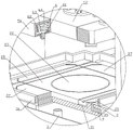
FIG. 1 is a first schematic structural view of an automatic folding and forming machine for lining of gift boxes in accordance with an embodiment of the present invention;
FIG. 2 is a schematic structural view of an automatic folding and forming machine for lining of gift boxes of the present invention;
FIG. 3 is an enlarged view of the structure at A in FIG. 2;
FIG. 4 is a first schematic sectional view of an automatic folding machine for lining of gift box of the present invention;
FIG. 5 is an enlarged view of the structure at B in FIG. 4;
FIG. 6 is a schematic cross-sectional view of a second embodiment of the present invention;
FIG. 7 is a third schematic sectional view of an automatic folding machine for lining of gift boxes in accordance with an embodiment of the present invention;
FIG. 8 is a schematic view of a carrier structure of an embodiment of an automatic folding machine for a liner of a gift box of the present invention;
FIG. 9 is a schematic view of a portion of an automatic folding machine for forming a liner of a gift box according to an embodiment of the present invention;
fig. 10 is a schematic view of a specific prior art inner lining of a gift box.
The main element symbols are as follows:
the support table 1, a first arched bracket 2, a cross-shaped assembly groove 21, a circular base plate 22, a square base plate 23, a first gap 24, a first special-shaped base plate 25, a second gap 26, a second special-shaped base plate 27, a third gap 28, a cylindrical support rod 3, an octagonal support plate 31, a first air cylinder 32, a strip-shaped sliding groove 34, an L-shaped sliding groove 35, a limit groove 36, a strip-shaped sliding block 4, a first handle 41, a first limit block 42, a first L-shaped limit seat 43, a second limit block 44, a second L-shaped limit seat 45, a strip-shaped support block 46, a first scraper 47, a second scraper 48, a second arched bracket 5, a second air cylinder 51, a first mounting plate 512, a square pressing plate 52, a circular cutting knife 53, a third air cylinder 54, a second mounting plate, an octagonal pressing plate 56, a first special-shaped cutting knife 57, a second special-shaped cutting knife 58, a first circular groove 6, a second circular groove 61, the device comprises a top block 63, a spring 64, a control button 65, a material receiving box 7, a universal wheel 71, a second handle 711, a sponge sleeve 72, a rubber pad 73, a protection box 74, a baffle 75 and a connecting rod 76.
Detailed Description
In order that those skilled in the art can better understand the present invention, the following technical solutions are further described with reference to the accompanying drawings and examples.
As shown in fig. 1-10, the automatic folding and forming machine for gift box linings of the invention comprises a supporting table 1, a first arch-shaped support 2 is fixedly connected with the upper end of the supporting table 1, a cross-shaped assembly groove 21 is arranged in the middle of the upper end of the first arch-shaped support 2, a round backing plate 22 is arranged in the middle of the cross-shaped assembly groove 21, a square backing plate 23 fixedly connected with the cross-shaped assembly groove 21 is arranged on the outer side of the round backing plate 22, a first gap 24 is arranged between the round backing plate 22 and the square backing plate 23, first special-shaped backing plates 25 matched with the cross-shaped assembly groove 21 are arranged on the left and right sides of the square backing plate 23, two second gaps 26 are arranged between the two first special-shaped backing plates 25 and the cross-shaped assembly groove 21, second special-shaped backing plates 27 matched with the cross-shaped assembly groove 21 are arranged on the front and back sides, the lower ends of the two first special-shaped backing plates 25 and the two second special-shaped backing plates 27 are fixedly connected with two cylindrical support rods 3 which are in sliding connection with the first arched bracket 2, the lower ends of the cylindrical support rods 3 are fixedly connected with an octagonal support plate 31, the support table 1 is fixedly connected with a first air cylinder 32 which is matched with the octagonal support plate 31, the first air cylinder 32 is provided with a first telescopic rod which penetrates through the support table 1 and is fixedly connected with the octagonal support plate 31, the upper ends of the two first special-shaped backing plates 25 are respectively provided with a strip-shaped sliding groove 34, the strip-shaped sliding grooves 34 penetrate through the front side and the rear side of the first arched bracket 2, the left side and the right side of the upper end of the first arched bracket 2 are respectively provided with an L-shaped sliding groove 35 which is matched with the cross-shaped assembly groove 21, the front ends of the two L-shaped sliding grooves 35 are respectively provided with a, a first handle 41 is arranged between the two strip-shaped sliding blocks 4, the first handle 41 is positioned at the front ends of the two strip-shaped sliding blocks 4, the rear ends of the two strip-shaped sliding blocks 4 are respectively provided with a first limiting block 42, the front sides of the two strip-shaped sliding blocks 4 are respectively provided with a first L-shaped limiting seat 43 matched with the cross-shaped assembling groove 21, the two first L-shaped limiting seats 43 are respectively provided with a second limiting block 44 matched with the limiting groove 36, the second limiting block 44 is flush with the upper end of the first arched bracket 2, the rear sides of the two strip-shaped sliding blocks 4 are respectively provided with a second L-shaped limiting seat 45 matched with the cross-shaped assembling groove 21, the two second L-shaped limiting seats 45 are respectively provided with a strip-shaped supporting block 46 matched with the strip-shaped sliding groove 34, the strip-shaped supporting block 46 is flush with the upper end of the first arched bracket 2, a first scraper 47 is arranged between the two second L-shaped limiting seats 45, two second scraper, the upper end of the first arched bracket 2 is provided with a second arched bracket 5, the middle part of the upper end of the second arched bracket 5 is fixedly connected with a second air cylinder 51, the second air cylinder 51 is provided with a second telescopic rod, the second telescopic rod penetrates through the second arched bracket 5 and is fixedly connected with a first mounting plate 512, the first mounting plate 512 is in bolted connection with a square pressing plate 52 matched with a square backing plate 23, the lower end of the square pressing plate 52 is provided with a round cutter 53 matched with a first gap 24, the left side and the right side of the upper end of the second arched bracket 5 are fixedly connected with third air cylinders 54, the two third air cylinders 54 are respectively provided with a third telescopic rod, the two third telescopic rods penetrate through the second arched bracket 5 and are fixedly connected with a second mounting plate 551, the two second mounting plates 551 are in bolted connection with an octagonal pressing plate 56, the left side and the right side of the lower end of, the front side and the rear side of the lower end of the octagonal pressing plate 56 are respectively provided with a second special-shaped cutter 58 matched with the third gap 28, the square pressing plate 52 and the octagonal pressing plate 56 are respectively provided with a plurality of pushing mechanisms, each pushing mechanism comprises a first circular groove 6, the upper end of each first circular groove 6 is provided with a second circular groove 61, each first circular groove 6 is communicated with each second circular groove 61, the radius of each second circular groove 61 is larger than the radius of each first circular groove 6, the lower side of each second circular groove 61 is provided with a limiting wafer 62, the lower end of each limiting wafer 62 is fixedly connected with a top block 63 matched with the corresponding first circular groove 6, the upper end of each limiting wafer 62 is provided with a spring 64 matched with the corresponding second circular groove 61, one side of the upper end of the supporting table 1 is provided with a control button 65, the inner side of the supporting table 1 is provided with a controller, the controller is connected with, the second cylinder 51 and the third cylinder 54 are both electrically connected to the controller.
By adopting the technical scheme of the invention, the two first L-shaped limiting seats 43 are matched with the two second L-shaped limiting seats 45 for limiting the paper board; the two second limiting blocks 44 are matched with the strip-shaped supporting block 46 and used for supporting the paper boards; the two second limiting blocks 44 are matched with the two limiting grooves 36 for positioning the material carrying part, and when the second limiting blocks 44 are abutted against the limiting grooves 36, the paperboard is positioned right above the square backing plate 23; the two L-shaped sliding grooves 35 are matched with the two strip-shaped sliding blocks 4, so that the material loading part can slide back and forth; a first handle 41 is arranged between the two strip-shaped sliding blocks 4, so that a user can pull the material loading part conveniently; the two first limiting blocks 42 are matched with the first arched bracket 2 and used for preventing the loading part from being completely pulled out of the L-shaped sliding groove 35; the strip-shaped sliding groove 34 is used for the strip-shaped supporting block 46 to slide back and forth; the external power supply is used for supplying power to the device;
when the device is used, a paperboard is placed on the material carrying part, the paperboard is pushed to the position right above the square backing plate 23 through the first handle 41, the control button 65 is pressed, after the controller receives a signal of the control button 65, the second air cylinder 51 and the third air cylinder 54 are firstly controlled to be electrified to work, the second telescopic rod and the third telescopic rod are both stretched, the second telescopic rod is stretched to enable the square pressing plate 52 to drive the circular cutter 53 to move downwards, the circular cutter 53 is matched with the first gap 24 to cut the middle part of the paperboard into a circular shape, the third telescopic rod is stretched to enable the octagonal pressing plate 56 to drive the first special-shaped cutter 57 and the second special-shaped cutter 58 to move downwards, the first special-shaped cutter 57 and the second special-shaped cutter 58 are matched with the second gap 26 and the third gap 28 to cut the paperboard into a cross shape, after the second telescopic rod and the third telescopic rod are stretched, the controller controls the third air cylinder 54 to be electrified to work to enable the third telescopic, the third telescopic rod is contracted to enable the square pressing plate 52 to drive the circular cutter 53 to return, after the contraction of the third telescopic rod is finished, the controller controls the first air cylinder 32 to be electrified to work, the first telescopic rod is expanded to enable the octagonal supporting plate 31 to drive the two first special-shaped backing plates 25 and the two second special-shaped backing plates 27 to move upwards through the cylindrical supporting rod 3, when the two first special-shaped backing plates 25 and the two second special-shaped backing plates 27 rise, the cross-shaped paper plate is folded to enable the cross-shaped paper plate to be folded into a paper box lining shape, after the expansion of the first telescopic rod is finished, the controller controls the first air cylinder 32 and the second air cylinder 51 to be electrified to work to enable the first telescopic rod and the second telescopic rod to be contracted, the first telescopic rod is contracted to enable the octagonal supporting plate 31 to drive the first special-shaped backing plates 25 and the second special-shaped backing plates 27 to return, and the second telescopic rod, after the first telescopic rod and the second telescopic rod are contracted, the controller controls the first air cylinder 32, the second air cylinder 51 and the third air cylinder 54 to stop working, a user pulls out the material carrying part through the first handle 41, and the paper box lining and leftover materials thereof are taken out under the action of the first scraper blade 47 and the second scraper blade 48, so that the automatic folding forming of the gift box lining is completed; the first circular groove 6, the second circular groove 61, the limiting circular sheet 62, the top block 63 and the spring 64 are matched with each other, so that the carton lining and leftover materials thereof are prevented from being clamped on the circular cutter 53 or the first special-shaped cutter 57 and the second special-shaped cutter 58;
the invention provides an automatic gift box lining folding and forming machine which is used for automatically cutting and automatically folding and forming a specific gift box lining so as to improve the production efficiency and the product quality.
Preferably, the lower side of the supporting table 1 is provided with a material receiving box 7. By adopting the structure, a user can conveniently collect the gift box lining and leftover materials thereof. In fact, other structures for facilitating the collection of the gift box lining and its scraps by the user may be considered according to the circumstances.
Preferably, four universal wheels 71 are uniformly arranged at the lower end of the material receiving box 7. This configuration facilitates the user to move the receiving box 7 on the ground. In fact, other configurations that facilitate the movement of the receiving box 7 on the ground by the user are also conceivable, depending on the circumstances.
Preferably, a second handle 711 is arranged in front of the material receiving box 7. With such a structure, the control of the movement of the material receiving box 7 is convenient to use. In fact, other structures that facilitate the use of a device for controlling the movement of the receiving box 7 may be used, depending on the circumstances.
Preferably, a sponge sleeve 72 is arranged outside the first handle 41. With such a structure, the use feeling of the first handle 41 can be improved. In fact, other structures capable of improving the use feeling of the first handle 41 are also conceivable according to the circumstances.
Preferably, the rear end of the first arched bracket 2 is provided with a rubber pad 73 matched with the first limiting block 42. With the structure, a buffer function can be realized between the first arched bracket 2 and the first limiting block 42. In fact, other structures capable of buffering the space between the first arched bracket 2 and the first stopper 42 are also contemplated.
Preferably, a protective box 74 fixedly connected with the support table 1 is arranged outside the control button 65. With this configuration, the control button 65 can be prevented from being touched by mistake. In fact, other structures capable of preventing the control button 65 from being touched by mistake may be considered according to circumstances.
Preferably, the front side of the first arched bracket 2 is provided with a baffle 75 fixedly connected with the support table 1. With such a structure, the gift box lining and its leftover materials can be prevented from entering the lower side of the first arched bracket 2. In fact, other structures for preventing the gift box lining and its rim leftover from entering the lower side of the first arched bracket 2 may be used according to circumstances.
Preferably, a connecting rod 76 is arranged between the two first L-shaped limiting seats 43. By the structure, the structure of the material loading part can be more stable. In fact, other structures which can make the structure of the material loading part more stable can be considered according to the situation.
Preferably, the circular pad 22 is removably attached to the first arched bracket 2. Such a configuration facilitates cleaning of liner debris within the first gap 24. In fact, other configurations that facilitate cleaning of the liner debris within the first gap 24 are contemplated.
The foregoing embodiments are merely illustrative of the principles of the present invention and its efficacy, and are not to be construed as limiting the invention. Any person skilled in the art can modify or change the above-mentioned embodiments without departing from the spirit and scope of the present invention. Accordingly, it is intended that all equivalent modifications or changes which can be made by those skilled in the art without departing from the spirit and technical spirit of the present invention be covered by the claims of the present invention.
Claims (10)
1. Automatic forming machine of folding paper of gift box inside lining, including supporting table (1), its characterized in that: the supporting table is characterized in that a first arched support (2) is fixedly connected to the upper end of the supporting table (1), a cross-shaped assembly groove (21) is arranged in the middle of the upper end of the first arched support (2), a circular base plate (22) is arranged in the middle of the cross-shaped assembly groove (21), a square base plate (23) fixedly connected with the cross-shaped assembly groove (21) is arranged on the outer side of the circular base plate (22), a first gap (24) is arranged between the circular base plate (22) and the square base plate (23), first special-shaped base plates (25) matched with the cross-shaped assembly groove (21) are arranged on the left side and the right side of the square base plate (23), two second gaps (26) are arranged between the first special-shaped base plates (25) and the cross-shaped assembly groove (21), and second special-shaped base plates (27) matched with the cross-shaped assembly groove (, two third gaps (28) are arranged between the second special-shaped base plates (27) and the cross-shaped assembly groove (21), two first special-shaped base plates (25) and two second special-shaped base plates (27) are fixedly connected with two cylindrical support rods (3) which are in sliding connection with the first arched bracket (2), the lower ends of the cylindrical support rods (3) are fixedly connected with an octagonal support plate (31), the support table (1) is fixedly connected with a first air cylinder (32) which is matched with the octagonal support plate (31), the first air cylinder (32) is provided with a first telescopic rod, the first telescopic rod penetrates through the support table (1) and the octagonal support plate (31) and is fixedly connected with the octagonal support plate (31), the upper ends of the two first special-shaped base plates (25) are provided with bar-shaped sliding grooves (34), and the bar-shaped sliding grooves (34) penetrate through the front side and the back side of the, the left side and the right side of the upper end of the first arched bracket (2) are respectively provided with an L-shaped sliding groove (35) matched with the cross-shaped assembling groove (21), the front ends of the two L-shaped sliding grooves (35) are respectively provided with a limiting groove (36), the two L-shaped sliding grooves (35) are connected with a material carrying part in a sliding manner, the material carrying part comprises two strip-shaped sliding blocks (4) connected with the L-shaped sliding grooves (35) in a sliding manner, a first handle (41) is arranged between the two strip-shaped sliding blocks (4), the first handle (41) is positioned at the front ends of the two strip-shaped sliding blocks (4), the rear ends of the two strip-shaped sliding blocks (4) are respectively provided with a first limiting block (42), the front sides of the two strip-shaped sliding blocks (4) are respectively provided with a first L-shaped limiting seat (43) matched with the cross-shaped assembling groove (21), the two first L-shaped limiting seats (, the second limiting blocks (44) are flush with the upper end of the first arched bracket (2), the rear sides of the two strip-shaped sliding blocks (4) are respectively provided with a second L-shaped limiting seat (45) matched with the cross-shaped assembling groove (21), the two second L-shaped limiting seats (45) are respectively provided with a strip-shaped supporting block (46) matched with the strip-shaped sliding groove (34), the strip-shaped supporting blocks (46) are flush with the upper end of the first arched bracket (2), a first scraper (47) is arranged between the two second L-shaped limiting seats (45), two second scrapers (48) are arranged between the two first L-shaped limiting seats (43) and the two second L-shaped limiting seats (45), the upper end of the first arched bracket (2) is provided with a second arched bracket (5), the middle part of the upper end of the second arched bracket (5) is fixedly connected with a second air cylinder (51), and the second air cylinder (51) is provided with a second telescopic rod, the second telescopic link runs through the first mounting panel (512) of second arch support (5) fixedly connected with, first mounting panel (512) bolted connection have with square backing plate (23) assorted square clamp plate (52), square clamp plate (52) lower extreme is equipped with circular cutter (53) with first clearance (24) assorted, the equal fixedly connected with third cylinder (54) of second arch support (5) upper end left and right sides, two third cylinder (54) all are equipped with the third telescopic link, two the third telescopic link all runs through second arch support (5) fixedly connected with second mounting panel (551), two second mounting panel (551) bolted connection has octagon clamp plate (56), octagon clamp plate (56) lower extreme left and right sides all is equipped with first special-shaped cutter (57) with second clearance (26) assorted, both sides all are equipped with second clearance (28) assorted second clamp plate (56) lower extreme front and back sides Special-shaped cutter (58), square clamp plate (52) and octagon clamp plate (56) all are equipped with a plurality of ejecting mechanisms, ejecting mechanism includes first circular slot (6), first circular slot (6) upper end is equipped with second circular slot (61), first circular slot (6) and second circular slot (61) intercommunication, second circular slot (61) radius size is greater than first circular slot (6) radius size, second circular slot (61) downside is equipped with spacing disc (62), spacing disc (62) lower extreme fixedly connected with first circular slot (6) assorted kicking block (63), spacing disc (62) upper end be equipped with second circular slot (61) assorted spring (64), support table (1) upper end one side is equipped with control button (65), support table (1) inboard is equipped with the controller, the controller is connected with external power source, the control button (65) is in signal connection with the controller, and the first air cylinder (32), the second air cylinder (51) and the third air cylinder (54) are all electrically connected with the controller.
2. A gift box liner automatic folding machine of claim 1 wherein: the lower side of the supporting table (1) is provided with a material receiving box (7).
3. A gift box liner automatic folding machine of claim 2 wherein: four universal wheels (71) are uniformly arranged at the lower end of the material receiving box (7).
4. A gift box liner automatic folding machine of claim 3 wherein: a second handle (711) is arranged on the front side of the material receiving box (7).
5. A gift box liner automatic folding machine of claim 1 wherein: a sponge sleeve (72) is arranged on the outer side of the first handle (41).
6. A gift box liner automatic folding machine of claim 1 wherein: the rear end of the first arched bracket (2) is provided with a rubber pad (73) matched with the first limiting block (42).
7. A gift box liner automatic folding machine of claim 1 wherein: and a protection box (74) fixedly connected with the support table (1) is arranged on the outer side of the control button (65).
8. A gift box liner automatic folding machine of claim 1 wherein: the front side of the first arched bracket (2) is provided with a baffle (75) fixedly connected with the supporting table (1).
9. A gift box liner automatic folding machine of claim 1 wherein: a connecting rod (76) is arranged between the two first L-shaped limiting seats (43).
10. A gift box liner automatic folding machine of claim 1 wherein: the circular base plate (22) is detachably connected with the first arched bracket (2).
Priority Applications (1)
| Application Number | Priority Date | Filing Date | Title |
|---|---|---|---|
| CN201911282162.8A CN110920151B (en) | 2019-12-13 | 2019-12-13 | Automatic folding forming machine for gift box lining |
Applications Claiming Priority (1)
| Application Number | Priority Date | Filing Date | Title |
|---|---|---|---|
| CN201911282162.8A CN110920151B (en) | 2019-12-13 | 2019-12-13 | Automatic folding forming machine for gift box lining |
Publications (2)
| Publication Number | Publication Date |
|---|---|
| CN110920151A true CN110920151A (en) | 2020-03-27 |
| CN110920151B CN110920151B (en) | 2021-05-25 |
Family
ID=69859747
Family Applications (1)
| Application Number | Title | Priority Date | Filing Date |
|---|---|---|---|
| CN201911282162.8A Active CN110920151B (en) | 2019-12-13 | 2019-12-13 | Automatic folding forming machine for gift box lining |
Country Status (1)
| Country | Link |
|---|---|
| CN (1) | CN110920151B (en) |
Citations (7)
| Publication number | Priority date | Publication date | Assignee | Title |
|---|---|---|---|---|
| CN1285780A (en) * | 1997-12-03 | 2001-02-28 | 皮尔尼斯机器工具公司 | Pressed paper cut-in-place die |
| CN106626519A (en) * | 2016-12-23 | 2017-05-10 | 重庆皖渝纸制品有限公司 | Paperboard cutting and folding integrated machine |
| CN206186429U (en) * | 2016-09-27 | 2017-05-24 | 东莞鸿耀电子科技有限公司 | Automatic box folding machine |
| CN206551551U (en) * | 2017-02-23 | 2017-10-13 | 东莞市旭海机械有限公司 | A kind of tobacco and wine back box forming machine |
| CN207059316U (en) * | 2017-08-29 | 2018-03-02 | 瑞安市科达机械有限公司 | A kind of shaped device of gift box kludge |
| CN207859572U (en) * | 2018-01-30 | 2018-09-14 | 易润琳 | A kind of food packaging material cutter |
| CN209409437U (en) * | 2018-12-14 | 2019-09-20 | 美物产品设计(广州)有限责任公司 | A kind of gift box device for automatically molding |
-
2019
- 2019-12-13 CN CN201911282162.8A patent/CN110920151B/en active Active
Patent Citations (7)
| Publication number | Priority date | Publication date | Assignee | Title |
|---|---|---|---|---|
| CN1285780A (en) * | 1997-12-03 | 2001-02-28 | 皮尔尼斯机器工具公司 | Pressed paper cut-in-place die |
| CN206186429U (en) * | 2016-09-27 | 2017-05-24 | 东莞鸿耀电子科技有限公司 | Automatic box folding machine |
| CN106626519A (en) * | 2016-12-23 | 2017-05-10 | 重庆皖渝纸制品有限公司 | Paperboard cutting and folding integrated machine |
| CN206551551U (en) * | 2017-02-23 | 2017-10-13 | 东莞市旭海机械有限公司 | A kind of tobacco and wine back box forming machine |
| CN207059316U (en) * | 2017-08-29 | 2018-03-02 | 瑞安市科达机械有限公司 | A kind of shaped device of gift box kludge |
| CN207859572U (en) * | 2018-01-30 | 2018-09-14 | 易润琳 | A kind of food packaging material cutter |
| CN209409437U (en) * | 2018-12-14 | 2019-09-20 | 美物产品设计(广州)有限责任公司 | A kind of gift box device for automatically molding |
Also Published As
| Publication number | Publication date |
|---|---|
| CN110920151B (en) | 2021-05-25 |
Similar Documents
| Publication | Publication Date | Title |
|---|---|---|
| CN104285914B (en) | A kind of de-cocoon machine and using method thereof | |
| CN108527468B (en) | A kind of corrugated paper trimming device | |
| CN110920151B (en) | Automatic folding forming machine for gift box lining | |
| CN112372681A (en) | Books leave factory side cut equipment | |
| US2506021A (en) | Machine for wrapping folded sheets | |
| CN216266267U (en) | Cutting device with waste collecting performance for production of environment-friendly paper products | |
| JP3198988U (en) | Food cutting machine | |
| CN106891573A (en) | A kind of kit Full-automatic assembling machine | |
| CN201677540U (en) | Rotary drum type paperboard grooving machine | |
| CN106181679B (en) | One kind is used for hinge core full-automatic sanding production equipment | |
| CN105415552A (en) | Novel rubber cutting device for rubber refining mill | |
| JP5118993B2 (en) | Tatami cutting device | |
| CN104097105A (en) | Material pushing mechanism of numerical control machine tool | |
| CN109228518A (en) | A kind of packing box making apparatus | |
| CN103787128B (en) | A kind of stack pallet with clipping function | |
| CN205571521U (en) | Lathe of keyway planer | |
| CN106737931B (en) | Convenient for the coconut palm plate bead cutter of feeding | |
| CN107891480B (en) | Die cutting machine | |
| CN106827121B (en) | Device for coconut palm plate trimming | |
| CN220053044U (en) | Packaging paperboard shearing machine | |
| CN111112733A (en) | Auxiliary device for unloading cutter of slitting machine | |
| CN104191460B (en) | A kind of production line for wall surface paster substrate cut | |
| CN210210550U (en) | Cutting device for composite paperboard | |
| CN216300172U (en) | Angle pressing device on laminating machine | |
| CN204700910U (en) | A kind of disconnecting materials device |
Legal Events
| Date | Code | Title | Description |
|---|---|---|---|
| PB01 | Publication | ||
| PB01 | Publication | ||
| SE01 | Entry into force of request for substantive examination | ||
| SE01 | Entry into force of request for substantive examination | ||
| GR01 | Patent grant | ||
| GR01 | Patent grant |