CN110917841B - Waste gas treatment system used in electroplating process and working method thereof - Google Patents
Waste gas treatment system used in electroplating process and working method thereof Download PDFInfo
- Publication number
- CN110917841B CN110917841B CN201911007488.XA CN201911007488A CN110917841B CN 110917841 B CN110917841 B CN 110917841B CN 201911007488 A CN201911007488 A CN 201911007488A CN 110917841 B CN110917841 B CN 110917841B
- Authority
- CN
- China
- Prior art keywords
- pipeline
- air
- processor
- pipe
- reaction
- Prior art date
- Legal status (The legal status is an assumption and is not a legal conclusion. Google has not performed a legal analysis and makes no representation as to the accuracy of the status listed.)
- Active
Links
- 238000009713 electroplating Methods 0.000 title claims abstract description 64
- 239000002912 waste gas Substances 0.000 title claims abstract description 55
- 238000000034 method Methods 0.000 title claims abstract description 39
- 238000006243 chemical reaction Methods 0.000 claims abstract description 67
- 238000000605 extraction Methods 0.000 claims abstract description 41
- 230000003647 oxidation Effects 0.000 claims abstract description 38
- 238000007254 oxidation reaction Methods 0.000 claims abstract description 38
- 239000003054 catalyst Substances 0.000 claims abstract description 34
- 230000001590 oxidative effect Effects 0.000 claims abstract description 25
- 239000007789 gas Substances 0.000 claims abstract description 24
- 238000006552 photochemical reaction Methods 0.000 claims abstract description 22
- 238000012545 processing Methods 0.000 claims abstract description 22
- 238000001802 infusion Methods 0.000 claims abstract 4
- XLYOFNOQVPJJNP-UHFFFAOYSA-N water Substances O XLYOFNOQVPJJNP-UHFFFAOYSA-N 0.000 claims description 41
- 239000007800 oxidant agent Substances 0.000 claims description 20
- 239000007788 liquid Substances 0.000 claims description 18
- 239000007921 spray Substances 0.000 claims description 18
- 238000012806 monitoring device Methods 0.000 claims description 17
- 238000011084 recovery Methods 0.000 claims description 11
- 239000000284 extract Substances 0.000 claims description 9
- 238000007789 sealing Methods 0.000 claims description 8
- 239000003795 chemical substances by application Substances 0.000 claims description 4
- 239000002699 waste material Substances 0.000 claims description 4
- 238000009423 ventilation Methods 0.000 claims 7
- DNHVXYDGZKWYNU-UHFFFAOYSA-N lead;hydrate Chemical compound O.[Pb] DNHVXYDGZKWYNU-UHFFFAOYSA-N 0.000 claims 4
- 238000004891 communication Methods 0.000 claims 1
- 238000007747 plating Methods 0.000 description 11
- 238000005086 pumping Methods 0.000 description 9
- 239000002253 acid Substances 0.000 description 5
- 239000003814 drug Substances 0.000 description 4
- 239000000126 substance Substances 0.000 description 4
- 238000004064 recycling Methods 0.000 description 3
- QGZKDVFQNNGYKY-UHFFFAOYSA-N Ammonia Chemical compound N QGZKDVFQNNGYKY-UHFFFAOYSA-N 0.000 description 2
- XFXPMWWXUTWYJX-UHFFFAOYSA-N Cyanide Chemical compound N#[C-] XFXPMWWXUTWYJX-UHFFFAOYSA-N 0.000 description 2
- 239000003513 alkali Substances 0.000 description 2
- 238000004519 manufacturing process Methods 0.000 description 2
- 238000012544 monitoring process Methods 0.000 description 2
- JMANVNJQNLATNU-UHFFFAOYSA-N oxalonitrile Chemical compound N#CC#N JMANVNJQNLATNU-UHFFFAOYSA-N 0.000 description 2
- 239000000654 additive Substances 0.000 description 1
- 229910021529 ammonia Inorganic materials 0.000 description 1
- 239000002585 base Substances 0.000 description 1
- 230000009286 beneficial effect Effects 0.000 description 1
- 230000005540 biological transmission Effects 0.000 description 1
- KRVSOGSZCMJSLX-UHFFFAOYSA-L chromic acid Substances O[Cr](O)(=O)=O KRVSOGSZCMJSLX-UHFFFAOYSA-L 0.000 description 1
- 239000000428 dust Substances 0.000 description 1
- 238000003912 environmental pollution Methods 0.000 description 1
- AWJWCTOOIBYHON-UHFFFAOYSA-N furo[3,4-b]pyrazine-5,7-dione Chemical compound C1=CN=C2C(=O)OC(=O)C2=N1 AWJWCTOOIBYHON-UHFFFAOYSA-N 0.000 description 1
- 238000010438 heat treatment Methods 0.000 description 1
- 238000005286 illumination Methods 0.000 description 1
- 230000008595 infiltration Effects 0.000 description 1
- 238000001764 infiltration Methods 0.000 description 1
- 150000002500 ions Chemical class 0.000 description 1
- 239000000463 material Substances 0.000 description 1
- 239000002184 metal Substances 0.000 description 1
- 239000003595 mist Substances 0.000 description 1
- 238000012986 modification Methods 0.000 description 1
- 230000004048 modification Effects 0.000 description 1
- 230000003472 neutralizing effect Effects 0.000 description 1
- 239000010815 organic waste Substances 0.000 description 1
- 238000000746 purification Methods 0.000 description 1
- 230000035484 reaction time Effects 0.000 description 1
- 238000004381 surface treatment Methods 0.000 description 1
- 231100000331 toxic Toxicity 0.000 description 1
- 230000002588 toxic effect Effects 0.000 description 1
- 239000002351 wastewater Substances 0.000 description 1
Images


Classifications
-
- B—PERFORMING OPERATIONS; TRANSPORTING
- B01—PHYSICAL OR CHEMICAL PROCESSES OR APPARATUS IN GENERAL
- B01D—SEPARATION
- B01D53/00—Separation of gases or vapours; Recovering vapours of volatile solvents from gases; Chemical or biological purification of waste gases, e.g. engine exhaust gases, smoke, fumes, flue gases, aerosols
- B01D53/34—Chemical or biological purification of waste gases
- B01D53/74—General processes for purification of waste gases; Apparatus or devices specially adapted therefor
- B01D53/75—Multi-step processes
-
- B—PERFORMING OPERATIONS; TRANSPORTING
- B01—PHYSICAL OR CHEMICAL PROCESSES OR APPARATUS IN GENERAL
- B01D—SEPARATION
- B01D53/00—Separation of gases or vapours; Recovering vapours of volatile solvents from gases; Chemical or biological purification of waste gases, e.g. engine exhaust gases, smoke, fumes, flue gases, aerosols
- B01D53/34—Chemical or biological purification of waste gases
- B01D53/74—General processes for purification of waste gases; Apparatus or devices specially adapted therefor
- B01D53/77—Liquid phase processes
- B01D53/78—Liquid phase processes with gas-liquid contact
-
- B—PERFORMING OPERATIONS; TRANSPORTING
- B01—PHYSICAL OR CHEMICAL PROCESSES OR APPARATUS IN GENERAL
- B01D—SEPARATION
- B01D53/00—Separation of gases or vapours; Recovering vapours of volatile solvents from gases; Chemical or biological purification of waste gases, e.g. engine exhaust gases, smoke, fumes, flue gases, aerosols
- B01D53/34—Chemical or biological purification of waste gases
- B01D53/74—General processes for purification of waste gases; Apparatus or devices specially adapted therefor
- B01D53/86—Catalytic processes
Landscapes
- Engineering & Computer Science (AREA)
- Environmental & Geological Engineering (AREA)
- Chemical & Material Sciences (AREA)
- Health & Medical Sciences (AREA)
- Biomedical Technology (AREA)
- Analytical Chemistry (AREA)
- General Chemical & Material Sciences (AREA)
- Oil, Petroleum & Natural Gas (AREA)
- Chemical Kinetics & Catalysis (AREA)
- Chemically Coating (AREA)
Abstract
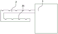
本发明涉及一种用于电镀工艺过程中的废气处理系统及其工作方法,包括:处理腔室、处理器;处理腔室包括抽气模块、反应模块;处理腔室上设置有导气口,导气口贯通处理腔室;抽气模块包括循环泵、抽气管道;抽气管道上设置有若干第一进气口;抽气管道内设置有抽气内管道,抽气管道套设于抽气内管道外,抽气内管道上设置有第二进气口;反应模块包括光化学反应装置、氧化装置、触媒层;触媒层设置于第二进气口上,触媒层用于覆盖第二进气口,电镀废气穿过触媒层并与触媒层进行反应;光化学反应装置环绕第二进气口的内侧设置;氧化装置设置于抽气内管道中,氧化装置包括氧化喷头与输液管道,氧化喷头与处理器连接。
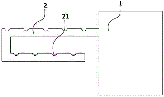
The invention relates to a waste gas treatment system used in an electroplating process and a working method thereof, comprising: a treatment chamber and a processor; the treatment chamber includes an air extraction module and a reaction module; The air outlet runs through the processing chamber; the air extraction module includes a circulation pump and an air extraction pipeline; a plurality of first air inlets are arranged on the air extraction pipeline; an air extraction inner pipeline is arranged in the air extraction pipeline, and the air extraction pipeline is sleeved outside the air extraction inner pipeline , a second air inlet is arranged on the inner exhaust pipe; the reaction module includes a photochemical reaction device, an oxidation device, and a catalyst layer; the catalyst layer is arranged on the second air inlet, and the catalyst layer is used to cover the second air inlet, and the electroplating exhaust gas Passing through the catalyst layer and reacting with the catalyst layer; the photochemical reaction device is arranged around the inner side of the second air inlet; the oxidizing device is arranged in the inner pipeline of the gas extraction, and the oxidizing device comprises an oxidizing nozzle and an infusion pipeline, and the oxidizing nozzle is connected with the processor.
Description
Claims (7)
Priority Applications (1)
| Application Number | Priority Date | Filing Date | Title |
|---|---|---|---|
| CN201911007488.XA CN110917841B (en) | 2019-10-22 | 2019-10-22 | Waste gas treatment system used in electroplating process and working method thereof |
Applications Claiming Priority (1)
| Application Number | Priority Date | Filing Date | Title |
|---|---|---|---|
| CN201911007488.XA CN110917841B (en) | 2019-10-22 | 2019-10-22 | Waste gas treatment system used in electroplating process and working method thereof |
Publications (2)
| Publication Number | Publication Date |
|---|---|
| CN110917841A CN110917841A (en) | 2020-03-27 |
| CN110917841B true CN110917841B (en) | 2021-09-21 |
Family
ID=69849460
Family Applications (1)
| Application Number | Title | Priority Date | Filing Date |
|---|---|---|---|
| CN201911007488.XA Active CN110917841B (en) | 2019-10-22 | 2019-10-22 | Waste gas treatment system used in electroplating process and working method thereof |
Country Status (1)
| Country | Link |
|---|---|
| CN (1) | CN110917841B (en) |
Family Cites Families (16)
| Publication number | Priority date | Publication date | Assignee | Title |
|---|---|---|---|---|
| US4279624A (en) * | 1978-09-28 | 1981-07-21 | Wilson Joseph G | Downflow separator method and apparatus |
| US4262608A (en) * | 1979-06-14 | 1981-04-21 | Jackson Bert W | Method and apparatus for powered flue products exhaust and preheated combustion air supply |
| US8115373B2 (en) * | 2005-07-06 | 2012-02-14 | Rochester Institute Of Technology | Self-regenerating particulate trap systems for emissions and methods thereof |
| EP2351133A1 (en) * | 2008-10-28 | 2011-08-03 | Alan Devoe | Fuel cell device and system |
| CN202350041U (en) * | 2011-12-09 | 2012-07-25 | 冀州市沃尔堡供热设备有限公司 | Air supply and exhaust pipe for fuel combustion devices |
| CN202666658U (en) * | 2012-05-08 | 2013-01-16 | 张士昱 | Cylindrical wet separator for absorbing gas |
| CN204656225U (en) * | 2015-05-12 | 2015-09-23 | 河南省万隆精密铸造股份有限公司 | A kind of foundry waste gas cleaning system |
| CN205461652U (en) * | 2016-02-23 | 2016-08-17 | 东莞市基一核材有限公司 | Intake pipe structure that can purify air |
| CN205965498U (en) * | 2016-07-27 | 2017-02-22 | 佛山瀚兽环境科技服务有限公司 | A air treatment pipe and VOC gas handling system for VOC gas handling system |
| CN106110888B (en) * | 2016-08-31 | 2019-07-02 | 威洁(石狮)中水回用技术有限公司 | A kind of organic waste gas treatment equipment and method |
| CN207179921U (en) * | 2017-06-08 | 2018-04-03 | 天津市管道工程集团有限公司 | A kind of discharge duct that may filter that cleaning |
| CN206996215U (en) * | 2017-07-12 | 2018-02-13 | 重庆第二师范学院 | Chemically react exhaust gas treating device |
| CN208032201U (en) * | 2018-01-31 | 2018-11-02 | 广州六恩环保科技有限公司 | A kind of ventilation shaft with exhaust-gas treatment function |
| CN208711416U (en) * | 2018-08-31 | 2019-04-09 | 龙游龙辉电镀有限公司 | It is a kind of for handle plating exhaust gas exhaust gas treating tower |
| CN110180360A (en) * | 2019-05-29 | 2019-08-30 | 杭州富阳申能固废环保再生有限公司 | More one tower flue gas processing systems of furnace |
| CN110302670B (en) * | 2019-07-29 | 2021-10-22 | 平顶山瑞平石龙水泥有限公司 | High temperature industry flue gas desulfurization denitration treatment device |
-
2019
- 2019-10-22 CN CN201911007488.XA patent/CN110917841B/en active Active
Also Published As
| Publication number | Publication date |
|---|---|
| CN110917841A (en) | 2020-03-27 |
Similar Documents
| Publication | Publication Date | Title |
|---|---|---|
| CN207210045U (en) | A kind of vulcanization reaction device for handling the waste water containing heavy metal-polluted acid | |
| CN110917841B (en) | Waste gas treatment system used in electroplating process and working method thereof | |
| CN218249476U (en) | Glove box for experiments | |
| CN211612238U (en) | Acid mist treatment device | |
| CN219149746U (en) | Laboratory chlorine acid mist purifier | |
| CN219376652U (en) | Odor treatment system and wastewater treatment station | |
| CN219848671U (en) | Biochemical treatment equipment for VOCs (volatile organic compounds) in internal mixing waste gas of tire | |
| CN205672769U (en) | A kind of exhaust gas recovery system | |
| CN109351163A (en) | Simple deodorization device between a kind of sludge | |
| CN211585935U (en) | Waste gas treatment device for environmental protection equipment | |
| CN210699531U (en) | Harmful gas processing apparatus for environmental protection engineering | |
| CN211358312U (en) | Waste gas treatment device based on chemical washing deodorization | |
| CN209501328U (en) | A kind of emission-control equipment | |
| CN208705720U (en) | Safe and environmentally friendly disposal system for hazardous chemical | |
| CN220310125U (en) | Chlorination paraffin preparation tail gas dechlorination device | |
| CN213314304U (en) | High-efficient spray column | |
| CN215086128U (en) | A waste gas treatment device for electroplating metal products | |
| CN218741207U (en) | Poisonous and harmful waste gas purifying equipment | |
| CN217265161U (en) | Ozone oxidation electroplating wastewater treatment device | |
| CN219596278U (en) | Purifying device for waste gas of earth acid | |
| CN214287504U (en) | Waste gas treatment device of high-performance water reducing agent production equipment | |
| CN212924521U (en) | Chromium-containing wastewater reduction neutralization and waste gas treatment integrated equipment | |
| CN219050795U (en) | Combined waste gas purifying treatment equipment | |
| CN106345258A (en) | Acid mist treatment method | |
| CN216092831U (en) | Waste gas treatment device |
Legal Events
| Date | Code | Title | Description |
|---|---|---|---|
| PB01 | Publication | ||
| PB01 | Publication | ||
| SE01 | Entry into force of request for substantive examination | ||
| SE01 | Entry into force of request for substantive examination | ||
| TA01 | Transfer of patent application right | ||
| TA01 | Transfer of patent application right |
Effective date of registration: 20210902 Address after: 236300 Funan County Industrial Park in Fuyang, Anhui Applicant after: Anhui Hongyuan electroplating surface treatment Co.,Ltd. Address before: 215400 room 402, building 58, Dexing first village, Taicang City, Suzhou City, Jiangsu Province Applicant before: Jin Chi |
|
| GR01 | Patent grant | ||
| GR01 | Patent grant | ||
| PE01 | Entry into force of the registration of the contract for pledge of patent right | ||
| PE01 | Entry into force of the registration of the contract for pledge of patent right |
Denomination of invention: A waste gas treatment system and its working method for electroplating process Granted publication date: 20210921 Pledgee: Industrial and Commercial Bank of China Limited Funan Branch Pledgor: Anhui Hongyuan electroplating surface treatment Co.,Ltd. Registration number: Y2024980057733 |
|
| PC01 | Cancellation of the registration of the contract for pledge of patent right | ||
| PC01 | Cancellation of the registration of the contract for pledge of patent right |
Granted publication date: 20210921 Pledgee: Industrial and Commercial Bank of China Limited Funan Branch Pledgor: Anhui Hongyuan electroplating surface treatment Co.,Ltd. Registration number: Y2024980057733 |