CN110916397A - Full-automatic office chair capable of deeply lying down - Google Patents
Full-automatic office chair capable of deeply lying down Download PDFInfo
- Publication number
- CN110916397A CN110916397A CN201911246321.9A CN201911246321A CN110916397A CN 110916397 A CN110916397 A CN 110916397A CN 201911246321 A CN201911246321 A CN 201911246321A CN 110916397 A CN110916397 A CN 110916397A
- Authority
- CN
- China
- Prior art keywords
- plate
- rod
- connecting rod
- seat plate
- seat
- Prior art date
- Legal status (The legal status is an assumption and is not a legal conclusion. Google has not performed a legal analysis and makes no representation as to the accuracy of the status listed.)
- Pending
Links
- 230000007246 mechanism Effects 0.000 claims abstract description 40
- 230000009471 action Effects 0.000 claims abstract description 16
- 238000006243 chemical reaction Methods 0.000 claims abstract description 16
- 230000033001 locomotion Effects 0.000 claims description 10
- 238000000034 method Methods 0.000 claims description 5
- 230000008569 process Effects 0.000 claims description 4
- 238000010297 mechanical methods and process Methods 0.000 claims 1
- 230000000630 rising effect Effects 0.000 claims 1
- 230000036544 posture Effects 0.000 description 25
- 238000010586 diagram Methods 0.000 description 7
- 244000309466 calf Species 0.000 description 5
- 230000001154 acute effect Effects 0.000 description 3
- 230000000694 effects Effects 0.000 description 3
- 210000002414 leg Anatomy 0.000 description 2
- 230000000284 resting effect Effects 0.000 description 2
- 210000003127 knee Anatomy 0.000 description 1
- 230000009347 mechanical transmission Effects 0.000 description 1
- 230000004048 modification Effects 0.000 description 1
- 238000012986 modification Methods 0.000 description 1
- 230000007704 transition Effects 0.000 description 1
Images

Classifications
-
- A—HUMAN NECESSITIES
- A47—FURNITURE; DOMESTIC ARTICLES OR APPLIANCES; COFFEE MILLS; SPICE MILLS; SUCTION CLEANERS IN GENERAL
- A47C—CHAIRS; SOFAS; BEDS
- A47C1/00—Chairs adapted for special purposes
- A47C1/02—Reclining or easy chairs
- A47C1/031—Reclining or easy chairs having coupled concurrently adjustable supporting parts
- A47C1/032—Reclining or easy chairs having coupled concurrently adjustable supporting parts the parts being movably-coupled seat and back-rest
- A47C1/03205—Reclining or easy chairs having coupled concurrently adjustable supporting parts the parts being movably-coupled seat and back-rest having adjustable and lockable inclination
- A47C1/03211—Reclining or easy chairs having coupled concurrently adjustable supporting parts the parts being movably-coupled seat and back-rest having adjustable and lockable inclination by electric motors
-
- A—HUMAN NECESSITIES
- A47—FURNITURE; DOMESTIC ARTICLES OR APPLIANCES; COFFEE MILLS; SPICE MILLS; SUCTION CLEANERS IN GENERAL
- A47C—CHAIRS; SOFAS; BEDS
- A47C1/00—Chairs adapted for special purposes
- A47C1/02—Reclining or easy chairs
- A47C1/031—Reclining or easy chairs having coupled concurrently adjustable supporting parts
- A47C1/034—Reclining or easy chairs having coupled concurrently adjustable supporting parts the parts including a leg-rest or foot-rest
- A47C1/0342—Reclining or easy chairs having coupled concurrently adjustable supporting parts the parts including a leg-rest or foot-rest in combination with movable backrest-seat unit or back-rest
Landscapes
- Health & Medical Sciences (AREA)
- Dentistry (AREA)
- General Health & Medical Sciences (AREA)
- Chairs For Special Purposes, Such As Reclining Chairs (AREA)
Abstract
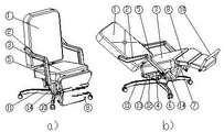
The invention discloses a full-automatic office chair capable of deeply lying, which relates to the field of office furniture, and adopts a unique mode to skillfully complete the easy conversion from a sitting posture to a full-body deep lying posture through a mechanical four-bar mechanism, wherein a user can randomly adjust the lying angle according to requirements in the conversion, so that the body is in a fully relaxed deep lying rest state, the full-automatic office chair is provided with a lower leg plate 8 and a foot pedaling rod 10, and each part of the body is more comfortable and easy under the action of the lower leg plate 8 and the foot pedaling rod 10 when the user lies down.
Description
Technical Field
The invention relates to the field of office furniture.
Background
In the office furniture industry, a large number of office chairs which can be used for sitting and lying and have various styles are available, the chairs on the market are basically the same in operation principle, seat plates of the chairs are all fixed, a backrest can only be backwards laid when a rest is needed, most of the chairs do not have the function of lifting shanks, only a drawable leg placing plate is arranged, the use is inconvenient, more importantly, the office chair which can be laid is not the optimal posture for lying and resting of a body in the lying posture, the lying and resting effect cannot be well achieved, the invention is completely designed aiming at the novel and completely changes the posture when the body is laid, the seat plates are not horizontally placed when the lying posture, the hip position is lower than the knee part, and the S lying type lying state (lying S state) for making the body deep is achieved, the shank is also lifted automatically, the seat is freely converted in two postures by adopting a fully automatic control party, and the actions are simple and reliable by adopting four-bar mechanisms.
Disclosure of Invention
The full-automatic seat capable of deeply lying is very simple and convenient to use, the sitting posture or the lying posture can be adjusted at will only by controlling the switch in use, a body can lie down to any angle (within the maximum lying angle), the seat plate 3 sinks by the hip position in the period, the included angle between the seat plate 3 and the ground is an acute angle, the calf plate 8 lifts the calf together with the calf plate, and the foot-treading rod 10 is lifted to step on the calf plate. The invention relates to a chair, which is characterized in that a seat plate 3 is hinged on a base 11, a back rest plate 1 is hinged with the seat plate 3, a lower leg plate 8 is hinged with the seat plate 3, and a foot kicking rod 10 is hinged with the lower leg plate 8. the chair adopts the most basic mechanical transmission mode, so that when the rear part of the seat plate 3 sinks, the back rest plate 1 falls backwards, the lower leg plate 8 lifts upwards, the foot kicking rod 10 is also lifted, when the chair is in a chair state, the back rest plate 1 and the seat plate 3 form a vertical angle, the seat plate 3 and the ground have a small angle inclination, the lower leg plate 8 is collected under the seat plate 3, and the foot kicking rod 10 is collected in the front of the lower leg plate 8. The invention adopts a power to make the mechanism linkage achieve the free conversion of two postures. In the two posture conversion, any object in the invention is not required to be moved, and the method is simple and convenient.
Drawings
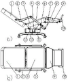
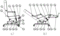
FIG. 1 is a three-dimensional effect diagram of a fully automatic office chair capable of lying down deeply according to the present invention in a sitting posture and a lying posture, wherein a in FIG. 1 is a three-dimensional effect diagram of the chair in the sitting posture, b in FIG. 1 is a three-dimensional effect diagram in the lying posture, FIG. 2 is a schematic diagram of the fully automatic office chair capable of lying down deeply according to the present invention in the sitting posture, in order to show a part of an extension plate of a swing lever 14 hidden in a mechanism diagram 2, a in FIG. 2 is a front view of the chair, b in FIG. 2 is a side view of the chair, FIG. 3 is a schematic diagram of the fully automatic office chair capable of lying down deeply according to the present invention in the lying down chair, in order to show a part of an extension plate of a swing lever 14 hidden in a mechanism diagram 3, a in FIG. 3 is a side view of the lying down chair, b in FIG. 3 is a top view in the lying down chair presentation, in order to explain the present inventionThe invention's action, especially set up figure 4, figure 4 is the side view when "full automatic office chair capable of deep lying down" presents seat and reclining chair, figure 4 a is the side view when presenting seat, figure 4 b is the side view when presenting reclining chair, in this figure the part of the elongated plate of part number 14 swing lever is hidden, and numbering is used to the axle center for the mechanism movement, from O1To O15The parts are marked as follows: 1 backrest board, 2 grab bar, 3 seat board, 4 two ends swing rod, 5 swing rod, 6 connecting rod, 7 curved connecting rod, 8 shank board, 9 pedal connecting rod, 10 pedal rod, 11 base, 12 short connecting rod, 13 motor, 14 swing rod, as can be seen in figure 4, the backrest board of part number 1 has axis O1、O2The part number 2 handrail rod is provided with an axis O1、O3The seat plate of part number 3 is provided with an axis O14、O2、O4、O5、O6The part number 5 swinging rod is provided with an axis O3、O4、O10、O11The base of the part number 11 is provided with an axis O13、O4The 6 connecting rod of the part number is provided with an axis O11、O12The 7 th bent connecting rod is provided with an axis O10、O7The pendulum rods at two ends of the part number 4 are provided with an axis O15、O13、O12The part number 8 shank plate is provided with an axis O6、O7、O8The member number 10 pedal rod is provided with an axis O9、O8The 9-member pedal connecting rod is provided with an axis O9、O5。
Detailed Description
The invention is explained in detail with the attached drawings, the invention adopts the traditional mechanical four-bar mechanism, and the mutual conversion between the sitting posture and the lying posture is free and simple when in use. The sitting posture of the backrest board 1, the seat board 3, the lower leg board 8 and the foot pedal rod 10 can be seen from the figures 1a and 2, and the sitting posture is mainly characterized in that the backrest board 1 is hinged with the seat board 3, the seat board 3 is hinged with the base 11 at O4The included angle between the backrest plate 1 and the seat plate 3 is 90 degrees, and the shank plate 8 and the seat plate 3 are hinged with each other at an angle O6The foot pedal rod 10 and the lower leg plate 8 are hinged with the O-shaped hinge part and are folded under the seat plate 38Collected in the smallIn the front of the leg plate 8, as can be seen from fig. 1b and 3, the seat is changed from the sitting posture to the lying-down posture, and the backrest plate 1 is hinged to the axis O at the leftmost end2An obtuse angle is formed between the seat plate 3 and the lower leg plate 8, the seat plate 3 sinks to form an acute angle with the ground at the position close to the backrest plate 1 in the middle, and the lower leg plate 3 and the seat plate 3 are hinged at the axis O6An obtuse angle with the seat plate 3 in the opposite direction, the foot-treading rod 10 and the lower leg plate 8 are hinged with the O8And is nearly perpendicular at an obtuse angle to the calf plate 8.
The following describes how to realize the conversion between the two states by referring to the drawings, firstly, each mechanism in the drawings is described, and as can be seen from fig. 2 and 3, a seat plate 3, two-end swing rods 4, a base 11 and a short connecting rod 12 form a first set of four-bar mechanisms which are used as the basis for the linkage of a complete set of seat mechanisms; the swing rods 4 at the two ends, the connecting rod 6, the base 11 and the swing rod 5 form a second set of four-bar mechanism; the backrest plate 1, the grab bar 2, the swinging rod 5 and the seat plate 3 form a third set of four-bar mechanism; the seat plate 3, the shank plate 8, the swinging rod 5 and the bent connecting rod 7 form a fourth set of four-bar mechanism; seat board 3, shank board 8, pedal foot pole 10, pedal connecting rod 9 constitute the fifth set of four-bar linkage, and the constitution of four-bar linkage respectively is by: the front end of the first four-bar mechanism seat plate 3 is hinged with the base 11 at the axle center O4(refer to fig. 2, 3, 4), the tail end is hinged with the short link 12 at the axle center O14The middle sections of the two oscillating bars 4 are hinged with the base 11 on the axle center O13One end is hinged with the short connecting rod 12 on the axle center O15(ii) a The second set of four-bar mechanism is that the middle sections of the two-end swing rods 4 are hinged with the base 11 at the axle center O13The other end is hinged with the connecting rod 6 at the axle center O12The connecting rod 6 is hinged with the swinging rod 5 and is connected with the axle center O11The swinging rod 5 and the base 11 are hinged on the axle center O4(ii) a The third set is that one end of the backrest plate 1 is hinged with the seat plate 3 and the axis O2,The middle section of the backrest plate 1 is hinged with the armrest rod 2 at the axle center O1The middle section of the swinging rod 5 is hinged with the base 11 at the axle center O4The other end is hinged with the handrail rod 2 at the axle center O3(ii) a The fourth set of four-bar mechanism is that the seat plate 3 is hinged with the swinging rod 5 and the axle center O4The foremost end of the shank plate is hinged with the shank plate 8 at the axis O6The shank plate 8 and the bent connecting rod 7 are hinged on the axle centerO7The bent connecting rod 7 is hinged with the swinging rod 5 and is connected with the axle center O10(ii) a The fifth set of four-bar mechanism is that the seat plate 3 is hinged with the lower leg plate 8 and the axle center O6Hinged with pedal connecting rod 9 and axial center O5The other end of the pedal connecting rod 9 is hinged with the pedal rod 10 at the axle center O9The foot pedal rod 10 and the lower leg plate 8 are hinged on the axle center O8The main mechanism of the two state transition is described.
The following describes the motion conversion process of the present invention in detail, looking at how to convert a chair into a reclining chair, referring to fig. 2, the motor 13 provides power to drive the two swing rods 4 of the first set of four-bar mechanism to rotate around the axis O13Rotate counterclockwise, so that the short connecting rod 12 drives the seat plate 3 to rotate around the axis O4The counterclockwise rotation, at this time, the counterclockwise rotation of the swing rods 4 at the two ends of the second set of four-bar mechanism makes the connecting rod 6 push the swing rod 5 to rotate around the axis O4The swinging rod 5 of the third four-bar mechanism drives the hand rail 2 to push the backrest plate 1 against the axle center O of the seat plate 3 counterclockwise2Rotate counterclockwise, and the fourth set of four-bar mechanism rotates around the axle center O at the swinging rod 54Under the action of counterclockwise rotation, the bent connecting rod 7 pushes the lower leg plate 8 to rotate around the axle center O of the seat plate 36The counterclockwise rotation causes the lower leg plate 8 to be gradually opened upwards, the pedal connecting rod 9 is pulled while the lower leg plate 8 is opened upwards, and the pedal rod 10 is wound around the axle center O of the lower leg plate 8 under the action of the pedal connecting rod 98The chair is rotated clockwise to be opened, and as can be seen from figure 3, one end of the seat plate 3 close to the backrest plate 1 sinks, so that an acute angle is formed between the seat plate 3 and the ground, an obtuse angle is formed between the backrest plate 1 and the seat plate 3, an obtuse angle in the opposite direction is formed between the lower leg plate 8 and the seat plate 3, and the foot-treading rod 10 is completely opened, so that the chair is the optimal posture for the body to lie down for rest, and it is required to be explained that the chair can be stopped and locked at any angle of lying down, and is adjusted by a user, so that the conversion from a sitting posture state to a lying posture state is completed. Turning to the figure 3, the motor 13 rotates in opposite directions to make the two swing rods 4 of the first four-bar mechanism rotate around the axis O13Rotate clockwise, so that the short connecting rod 12 drives the seat plate 3 to rotate around the axis O4Clockwise rotation, at the moment, the clockwise rotation of the swing rods 4 at the two ends of the second set of four-bar mechanism enables the connecting rod 6 to pull and swingThe rod 5 being about the axis O4The swinging rod 5 of the third set of four-bar mechanism drives the hand rail 2 clockwise to pull the backrest plate 1 relative to the axis O of the seat plate 3 by clockwise rotation2The fourth four-bar mechanism rotates clockwise, and simultaneously under the action of the clockwise rotation of the swinging rod 5, the bent connecting rod 7 pushes the lower leg plate 8 to rotate around the axis O of the seat plate 36Clockwise rotation gradually draws the lower leg plate 8 downwards, the pedal connecting rod 9 is pulled at the same time when the lower leg plate 8 downwards, and the pedal rod 10 winds the axle center O of the lower leg plate 8 under the action of the pedal connecting rod 98The back board 1 and the seat board 3 are slightly sunk, so that the angle between the seat board 3 and the ground is a small angle, the back board 1 and the seat board 3 are 90 degrees, the lower leg board 8 is collected right below the seat board 3 and slightly inwards folded, and the foot kicking rod 10 is completely attached to the lower leg board 8, thereby completing the conversion process from the lying posture to the sitting posture.
The foregoing is merely an example of the present invention and various modifications and changes may occur to those skilled in the art, and it is intended to cover in the appended claims any and all changes that fall within the true spirit and scope of the invention.
Claims (3)
1. The full-automatic office chair capable of deeply lying is mainly characterized in that when the chair is in a sitting posture, the backrest plate 1 is upright and forms an included angle of 90 degrees with the seat plate 3, and the seat plate 3 is hinged with the base 11 and is hinged with the O4Slightly inclined to the ground, the lower leg plate 8 is housed right below the seat plate 3, the footrest bar 10 is housed in the front of the lower leg plate, and the back rest plate 1 is laid down around the axis O2The counterclockwise direction inclines to form a pause angle with the seat plate 3, the lower leg plate 8 forms an obtuse angle with the seat plate 3 in the opposite direction, the pedal rod 10 and the lower leg plate 8 are in an open state and are approximately vertical, the conversion of the sitting posture and the lying posture is carried out under the constraint of a four-bar mechanism, and the posture conversion mode is a linkage posture conversion mode.
2. The conversion of the two states of the fully automatic office chair capable of deeply reclining according to claim 1 is performed by a conventional mechanical method and a multi-four-bar mechanism combined motion, so that the backrest board 1, the seat board 3, the lower leg board 8 and the foot pedal 10 complete the conversion from the sitting posture to the deeply reclining posture under the driving of one counterclockwise motion of the two swing rods 4, the conversion from the deeply reclining posture to the sitting posture is completed only by the clockwise motion of the two swing rods 4 when the deeply reclining posture is changed to the sitting posture, and the forward and reverse rotation of the two swing rods 4 is provided by one power.
3. In the action conversion according to claim 2, when converting from a chair to a deck chair, the first layer of four-bar mechanisms are composed of two-end swinging rods 4, a seat plate 3, a short connecting rod 12 and a base 11, wherein the two-end swinging rods 4 are driven by power to rotate around an axis O anticlockwise13The seat plate 3 is rotated around the axis O by the short connecting rod 124The second layer four-bar mechanism consists of two end oscillating bars 4, a connecting rod 6, an oscillating rod 5 and a base 11, wherein the oscillating bars 4 at the two ends drive the connecting rod 6 to push the oscillating rod 5 to rotate around the axis O4The counterclockwise motion makes the third set of four-bar mechanism follow the motion, the third set of four-bar mechanism is composed of a swinging rod 5, a seat plate 3, a backrest plate 1 and a handrail rod 2, under the motion of the swinging rod 5, the backrest plate 1 is driven to rotate around the axis O relative to the seat plate by the handrail rod 22The back board 1 and the seat board 3 are moved counterclockwise, the included angle between the back board 1 and the seat board 3 is increased along with the sinking of the back part of the seat board 3 in the linkage of the three sets of four-bar mechanisms, under the action of the swing rods 4 at the two ends, the fourth set of four-bar mechanisms simultaneously acts and consists of a swing rod 5, a seat plate 3, a shank plate 8 and a bent connecting rod 7, the bent connecting rod 7 pushes the shank plate 8 to be gradually opened upwards through the counterclockwise action of the swing rod 5, in the process of gradually opening the lower leg plate 8, the fifth set of four-bar mechanisms simultaneously acts and consists of the seat plate 3, the lower leg plate 8, the foot pedaling rod 10 and the pedal connecting rod 9, the lower leg plate 8 is relatively opened relative to the seat plate 3, so that the pedal connecting rod 9 acts to pull the foot pedaling rod 10 to be opened from the lower leg plate, therefore, the anticlockwise movement from sitting to lying by the swinging of the two ends 4 is finished, and when the lying posture is changed to the sitting posture, the swinging rods 4 at the two ends in the first layer of four-bar mechanism are driven by power to clockwise rotate around the axis O.13The seat plate 3 is rotated around the axis O by the short connecting rod 124Clockwise motion, second layer four-bar linkageIn the structure, the action of the swing rods 4 at two ends causes the connecting rod 6 to push the swing rod 5 to rotate around the axis O4Clockwise moves to make the third set of four-bar mechanism follow the action, under the action of the swinging rod 5, the armrest rod 2 makes the backrest plate 1 around the axis O relative to the seat plate2The angle between the backrest plate 1 and the seat plate 3 is reduced along with the rising of the rear part of the seat plate 3 in the linkage of the three sets of four-bar mechanisms, the fourth set of four-bar mechanisms simultaneously act under the action of the swing rods 4 at the two ends, the clockwise action of the swing rod 5 enables the bent connecting rod 7 to pull the shank plate 8 to gradually withdraw inwards, the fifth set of four-bar mechanisms simultaneously act in the process of gradually withdrawing the shank plate 8, the shank plate 8 is relatively folded in relative to the seat plate 3, the pedal connecting rod 9 acts to push the pedal rod 10 to be withdrawn into the shank plate, and thus the clockwise action of the swing rods 4 at the two ends is completed from lying to sitting.
Priority Applications (1)
| Application Number | Priority Date | Filing Date | Title |
|---|---|---|---|
| CN201911246321.9A CN110916397A (en) | 2019-12-08 | 2019-12-08 | Full-automatic office chair capable of deeply lying down |
Applications Claiming Priority (1)
| Application Number | Priority Date | Filing Date | Title |
|---|---|---|---|
| CN201911246321.9A CN110916397A (en) | 2019-12-08 | 2019-12-08 | Full-automatic office chair capable of deeply lying down |
Publications (1)
| Publication Number | Publication Date |
|---|---|
| CN110916397A true CN110916397A (en) | 2020-03-27 |
Family
ID=69857461
Family Applications (1)
| Application Number | Title | Priority Date | Filing Date |
|---|---|---|---|
| CN201911246321.9A Pending CN110916397A (en) | 2019-12-08 | 2019-12-08 | Full-automatic office chair capable of deeply lying down |
Country Status (1)
| Country | Link |
|---|---|
| CN (1) | CN110916397A (en) |
Citations (7)
| Publication number | Priority date | Publication date | Assignee | Title |
|---|---|---|---|---|
| FR2882507A1 (en) * | 2005-01-19 | 2006-09-01 | Sichelschmidt Stanzwerk | Chair comprises a rear part pivotably connected to a seat part via a hinge chain or a hinge lever |
| CN101016036A (en) * | 2006-02-06 | 2007-08-15 | 刘基农 | Series dual-purpose vehicle for sitting and lying and dual-purpose chair for sitting and lying |
| CN203106393U (en) * | 2013-02-05 | 2013-08-07 | 胡志东 | Dual-purpose back-rest chair for sitting and lying |
| CN204599905U (en) * | 2015-04-03 | 2015-09-02 | 深圳市特兴自动门有限公司 | Sitting-lying double-purpose office chair |
| CN105962666A (en) * | 2016-05-23 | 2016-09-28 | 太仓东泰精密机械有限公司 | Multifunctional seat for motor home |
| CN205696694U (en) * | 2016-04-05 | 2016-11-23 | 阿不都乃比·阿不都外力 | Fold double-purpose chair for lying and sitting |
| CN207152308U (en) * | 2017-03-20 | 2018-03-30 | 张艳 | A kind of chair with link gear |
-
2019
- 2019-12-08 CN CN201911246321.9A patent/CN110916397A/en active Pending
Patent Citations (7)
| Publication number | Priority date | Publication date | Assignee | Title |
|---|---|---|---|---|
| FR2882507A1 (en) * | 2005-01-19 | 2006-09-01 | Sichelschmidt Stanzwerk | Chair comprises a rear part pivotably connected to a seat part via a hinge chain or a hinge lever |
| CN101016036A (en) * | 2006-02-06 | 2007-08-15 | 刘基农 | Series dual-purpose vehicle for sitting and lying and dual-purpose chair for sitting and lying |
| CN203106393U (en) * | 2013-02-05 | 2013-08-07 | 胡志东 | Dual-purpose back-rest chair for sitting and lying |
| CN204599905U (en) * | 2015-04-03 | 2015-09-02 | 深圳市特兴自动门有限公司 | Sitting-lying double-purpose office chair |
| CN205696694U (en) * | 2016-04-05 | 2016-11-23 | 阿不都乃比·阿不都外力 | Fold double-purpose chair for lying and sitting |
| CN105962666A (en) * | 2016-05-23 | 2016-09-28 | 太仓东泰精密机械有限公司 | Multifunctional seat for motor home |
| CN207152308U (en) * | 2017-03-20 | 2018-03-30 | 张艳 | A kind of chair with link gear |
Similar Documents
| Publication | Publication Date | Title |
|---|---|---|
| CN204698851U (en) | Multifunction wheelchair | |
| ES2399840T3 (en) | Joint mechanism for a recliner | |
| CN104771281B (en) | Multifunctional wheelchair | |
| TW200423919A (en) | Wheelchair structure | |
| JPS5841511A (en) | Chair | |
| CN201523866U (en) | Chair with rotary keep-fit small backrest | |
| CN110013414B (en) | Massage chair | |
| KR102128494B1 (en) | Chair for elderly and disabled | |
| CN111602993A (en) | Sofa stretching device capable of providing zero-gravity sitting feeling | |
| CN110606097A (en) | Full-automatic business cabin capable of converting sitting posture, lying posture and sleeping posture into sleeping posture | |
| CN204930966U (en) | A kind of flexible leg rest mechanism of seat | |
| US4118046A (en) | Rocker assembly for wheelchairs | |
| CN213344998U (en) | Sofa with function of adjusting sitting posture | |
| CN110916397A (en) | Full-automatic office chair capable of deeply lying down | |
| CN209186058U (en) | One kind is transferred the files chair | |
| CN201260868Y (en) | Elastic body-building chair for sit-up | |
| CN212438005U (en) | Sofa stretching device capable of providing zero-gravity sitting feeling | |
| CN205885120U (en) | Multifunctional chair | |
| CN103284852A (en) | Seat type nursing bed | |
| CN109043936B (en) | Composite chair | |
| CN110840127A (en) | Sitting and lying dual-purpose office chair with leg lifting plate | |
| CN203815822U (en) | Frame for swinging massage chair | |
| CN211167267U (en) | Seat-standing lying three-state deformation device of lumbar vertebra twisting scooter | |
| CN208988185U (en) | A kind of flexible divan | |
| CN202496753U (en) | Chair with leg plate |
Legal Events
| Date | Code | Title | Description |
|---|---|---|---|
| PB01 | Publication | ||
| PB01 | Publication | ||
| SE01 | Entry into force of request for substantive examination | ||
| SE01 | Entry into force of request for substantive examination | ||
| RJ01 | Rejection of invention patent application after publication |
Application publication date: 20200327 |
|
| RJ01 | Rejection of invention patent application after publication |