Disclosure of Invention
In order to overcome the defect that the cost is high when the existing sapling correcting device corrects saplings, the technical problem of the invention is as follows: provides a sapling pull-down type correcting device which is low in cost and can correct saplings at any time.
The technical implementation scheme of the invention is as follows: a seedling pull-down correcting device comprises: a first mounting block; the pushing assembly is arranged on the front side of the first mounting block and pushes the first mounting block in a rotating mode; the connecting rod is arranged on the rear side of the first mounting block; the arc-shaped baffle is arranged at the right end of the connecting rod; the sliding assembly is arranged on the connecting rod and slides in a sliding mode; the supporting component is slidably arranged on the sliding component and is supported in a rotating mode; and the clamping assembly is arranged at the top end of the sliding assembly and is used for clamping in a sliding mode.
Further, the pushing assembly comprises an L-shaped threaded rod and an arc-shaped plate, a threaded hole is formed in the front side of the first mounting block, the L-shaped threaded rod is matched in the threaded hole, and the arc-shaped plate is mounted at the right end of the L-shaped threaded rod.
Further, the sliding assembly comprises a first sliding sleeve, a second sliding sleeve, a first sliding rod and a sliding block, the first sliding sleeve is arranged on the connecting rod in a sliding mode, the second sliding sleeve is installed on the first sliding sleeve in a rotating mode, the first sliding rod is arranged in the second sliding sleeve in a sliding mode, a sliding groove is formed in the right portion of the first sliding rod, and the sliding block is arranged on the sliding groove in a sliding mode.
Further, the supporting component is including the connecting rod, first arc piece, the second slide bar, second arc piece, first spring and tapered nut, install the connecting rod on the slider, first arc piece is installed to connecting rod right-hand member rotary type, two second slide bars are installed to the symmetry on the first arc piece, two equal slidingtype connections of second slide bar are on the second arc piece, the symmetry is opened on the second arc piece has the recess, recess and second slide bar sliding fit, be connected with first spring between second slide bar and the recess, first arc piece and second arc piece inboard all are opened threaded groove, the threaded groove fit has tapered nut.
Further, the clamping assembly comprises a first arc-shaped clamping plate, a threaded sleeve, a first guide sleeve, a second arc-shaped clamping plate and a cylindrical threaded rod, the first arc-shaped clamping plate is installed at the top end of the first sliding rod, the threaded sleeve is installed on the right portion of the front side of the first arc-shaped clamping plate, the first guide sleeve is sleeved on the outer side of the threaded sleeve, the second arc-shaped clamping plate is installed on the right end of the first guide sleeve, the cylindrical threaded rod is installed on the front side of the second arc-shaped clamping plate through a bearing seat, and the cylindrical threaded rod is matched with the threaded sleeve.
Further, the sapling pull-down correcting device further comprises a fixing assembly, the fixing assembly is installed in the clamping assembly and comprises a second installation block, a third arc-shaped clamping plate and a second spring, the second installation block is installed at the rear portion of the first guide sleeve, the third arc-shaped clamping plate is installed on the rear side of the second installation block in a rotating mode, and the second spring is connected between the third arc-shaped clamping plate and the second installation block.
Further, the sapling pull-down correcting device further comprises a clamping assembly, the clamping assembly is connected to the left side of the fixing assembly, the clamping assembly comprises a second guide sleeve, a wedge block and a third spring, the second guide sleeve is installed on the left portion of the third arc-shaped clamp plate, the wedge block is arranged in the second guide sleeve in a sliding mode, and the third spring is connected between the wedge block and the second guide sleeve.
The invention has the following advantages: the wood stick clamping device has the advantages that a large amount of manpower is saved by correcting bent trees through the pushing assembly, the wood stick clamping device is more convenient for people to use, the position of the fixed trees can be adjusted through the sliding assembly, the device can adapt to different bending angles and heights of the trees, people can take the device down more conveniently through the supporting assembly, the wood stick and the trees can be clamped more conveniently through the clamping assembly, the use of the people is more convenient, the wood stick can be further fixed through the fixing assembly, and the wood stick is prevented from falling down when the wood stick is clamped.
Drawings
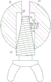
Fig. 1 is a schematic front view of the present invention.
Fig. 2 is a schematic diagram of a partial top view structure of the present invention.
Fig. 3 is a front view of the supporting assembly of the present invention.
FIG. 4 is a schematic top view of the support assembly of the present invention.
FIG. 5 is a schematic top view of the clamping assembly of the present invention.
FIG. 6 is a schematic top view of the chucking assembly of the present invention.
Fig. 7 is a left side view of the jamming assembly of the present invention.
In the above drawings: 1: first mounting block, 2: threaded hole, 3: l-shaped threaded rod, 4: arc-shaped plate, 5: connecting rod, 6: cowl, 7: first sliding sleeve, 8: second runner, 9: first slide bar, 10: chute, 11: slider, 12: a link, 121: first arc block, 122: second slide bar, 123: second arc block, 124: groove, 125: first spring, 126: thread groove, 127: cone nut, 13: first arc splint, 14: thread bush, 15: first guide bush, 16: second arc splint, 17: cylindrical threaded rod, 18: second mounting block, 19: third arc splint, 20: second spring, 21: second guide bush, 22: wedge block, 23: and a third spring.
Detailed Description
The technical solutions in the embodiments of the present invention will be clearly and completely described below with reference to the drawings in the embodiments of the present invention, and it is obvious that the described embodiments are only a part of the embodiments of the present invention, and not all of the embodiments. All other embodiments, which can be derived by a person skilled in the art from the embodiments given herein without making any creative effort, shall fall within the protection scope of the present invention.
Example 1
The utility model provides a sapling pull-down orthotic devices, as shown in fig. 1, 2, 3, 4 and 5, including first installation piece 1, promote the subassembly, connecting rod 5, cowl 6, the slip subassembly, supporting component and clamping component, the promotion subassembly that promotes through the pivoted mode is installed to first installation piece 1 front side, connecting rod 5 is installed to first installation piece 1 rear side, cowl 6 is installed to connecting rod 5 right-hand member, install on the connecting rod 5 and carry out gliding slip subassembly through gliding mode, install the supporting component that supports through the pivoted mode on the slip subassembly with sliding, the clamping component who presss from both sides tightly through gliding mode is installed on the slip subassembly top.
As shown in fig. 1 and 2, the pushing assembly comprises an L-shaped threaded rod 3 and an arc-shaped plate 4, a threaded hole 2 is formed in the front side of the first mounting block 1, the L-shaped threaded rod 3 is matched in the threaded hole 2, and the arc-shaped plate 4 is welded at the right end of the L-shaped threaded rod 3.
As shown in fig. 1, the sliding assembly includes a first sliding sleeve 7, a second sliding sleeve 8, a first sliding rod 9 and a sliding block 11, the connecting rod 5 is slidably provided with the first sliding sleeve 7, the second sliding sleeve 8 is rotatably installed on the top of the first sliding sleeve 7, the second sliding sleeve 8 is slidably provided with the first sliding rod 9, the first sliding rod 9 can slide up and down in the second sliding sleeve 8, the right portion of the first sliding rod 9 is provided with a sliding slot 10, and the sliding block 11 is slidably provided in the sliding slot 10.
As shown in fig. 1, 3 and 4, the supporting assembly includes a connecting rod 12, a first arc-shaped block 121, a second sliding rod 122, a second arc-shaped block 123, a first spring 125 and a cone-shaped nut 127, the connecting rod 12 is welded on the sliding block 11, the first arc-shaped block 121 is rotatably installed at the right end of the connecting rod 12, two second sliding rods 122 are symmetrically welded on the first arc-shaped block 121, the second sliding rod 122 is slidably fitted with the second arc-shaped block 123 (i.e., the two second sliding rods are both slidably connected to the second arc-shaped block), grooves 124 are symmetrically formed on the second arc-shaped block 123, the grooves 124 are slidably fitted with the second sliding rods 122, the first spring 125 is connected between the second sliding rod 122 and the grooves 124, thread grooves 126 are formed on the inner sides of the first arc-shaped block 121 and the second arc-shaped block 123, and the cone-shaped nut 127 is fitted in the thread grooves 126.
As shown in fig. 1 and 5, the clamping assembly comprises a first arc-shaped clamping plate 13, a threaded sleeve 14, a first guide sleeve 15, a second arc-shaped clamping plate 16 and a cylindrical threaded rod 17, the first arc-shaped clamping plate 13 is welded at the top end of the first sliding rod 9, the threaded sleeve 14 is installed at the right part of the front side of the first arc-shaped clamping plate 13, the first guide sleeve 15 is sleeved on the outer side of the threaded sleeve 14, the right end of the first guide sleeve 15 is fixedly connected with the second arc-shaped clamping plate 16 through a bolt, the cylindrical threaded rod 17 is installed at the front side of the second arc-shaped clamping plate 16 through a bearing seat, and the cylindrical threaded rod 17 is matched with the threaded sleeve 14.
The concrete operation of above-mentioned embodiment, when using this equipment to rectify trees, at first prepare a harder wooden rod, the wooden rod that will prepare is put to and is pasted flatly with trees department of buckling, it is tight with trees department of buckling to buckle wooden rod upper portion through clamping component afterwards, then the staff adjusts supporting component to the straight department of trees through sliding component, then the staff puts to the trees right side through cowl 6, afterwards the staff promotes the wooden rod lower part through promoting the subassembly and is close to trees, correct the back with trees, people tie up wooden rod and trees, prevent trees and buckle once more, afterwards the staff loosens clamping component and takes off equipment, so, make things convenient for people to use more.
When trees are corrected, the worker rotates the L-shaped threaded rod 3 to move rightwards in the threaded hole 2, the arc-shaped plate 4 moves rightwards along with the L-shaped threaded rod to push the lower portion of the wood stick to move rightwards, and therefore the bent trees are straightened, the tree straightening machine is more convenient for people to use, and a large amount of manpower is saved.
When the tree is corrected, the first sliding sleeve 7 is firstly slid to a proper position, the second sliding sleeve 8 is then slid left and right, the first sliding rod 9 is then slid up and down in the second sliding sleeve 8, the prepared wood stick is fixed after the first sliding rod slides to the proper position, and then the tree is corrected.
When the staff corrects trees, firstly, the conical nut 127 is screwed clockwise to extrude the first arc-shaped block 121 and the second arc-shaped block 123 to open towards two sides, the second arc-shaped block 123 slides outwards on the second sliding rod 122, the first spring 125 is stretched, after the conical nut 127 is adjusted to a proper position, the conical nut 127 stops rotating, then the trees are corrected, after the trees are corrected, the staff rotates the conical nut 127 anticlockwise, under the reset effect of the first spring 125, the second arc-shaped block 123 slides inwards to reset, and then the wood stick and the trees are bound to take down the equipment. Therefore, people can take the equipment down more conveniently.
When the staff presss from both sides the wood rod and the trees tightly, at first put the one end of the wood rod that has prepared in the department of trees buckling, the staff rotates cylindricality threaded rod 17 clockwise afterwards, first guide pin bushing 15 slides left on thread bush 14 thereupon, thereby it moves right with wood rod and trees clamp tightly to drive second arc splint 16, and then correct the trees of buckling, the wood rod finishes with trees are fixed, anticlockwise rotation cylindricality threaded rod 17 makes second arc splint 16 remove left and resets and can loosen equipment, so, more make things convenient for people to use.
Example 2
As shown in fig. 5, on the basis of embodiment 1, in order to better work of the device, the sapling pull-down straightening device further comprises a fixing assembly, the fixing assembly is installed in the clamping assembly, the fixing assembly comprises a second installation block 18, a third arc-shaped clamp plate 19 and a second spring 20, the second installation block 18 is welded at the rear part of the first guide sleeve 15, the third arc-shaped clamp plate 19 is rotatably installed at the rear side of the second installation block 18, and the second spring 20 is welded between the third arc-shaped clamp plate 19 and the second installation block 18.
As shown in fig. 5, 6 and 7, on the basis of embodiment 1, in order to more conveniently use the apparatus, the sapling pull-down correction device further includes a clamping component, the clamping component is connected to the left side of the fixing component, the clamping component includes a second guide sleeve 21, a wedge block 22 and a third spring 23, the left portion of the third arc-shaped clamp plate 19 is fixedly connected with the second guide sleeve 21 through a bolt, the second guide sleeve 21 is internally provided with the wedge block 22 in a sliding manner, and the third spring 23 is welded between the wedge block 22 and the second guide sleeve 21.
When the staff presss from both sides the wood rod and the trees tightly, at first forward rotate third arc splint 19, second spring 20 is compressed, then put the one end of wood rod in the department of buckling of trees, the staff loosens third arc splint 19 afterwards, under the effect that second spring 20 resets, third arc splint 19 rotate backward thereupon and reset and fix the wood rod, so, when pressing from both sides tight trees and wood rod, fix the wood rod earlier, so can prevent that the wood rod from falling down, people's work efficiency has been improved.
When a worker clamps a tree and a stick, the worker rotates the cylindrical threaded rod 17 to drive the first guide sleeve 15 to slide leftwards on the threaded sleeve 14, so that the second installation block 18 drives the third arc-shaped clamping plate 19 to slide leftwards, the second guide sleeve 21 slides leftwards, when the second guide sleeve 21 slides leftwards to be in contact with the first arc-shaped clamping plate 13, the first arc-shaped clamping plate 13 pushes the wedge block 22 to slide downwards in the second guide sleeve 21, the third spring 23 is extruded, after the first arc-shaped clamping plate 13 is separated from the wedge block 22, under the action of resetting of the third spring 23, the wedge block 22 slides downwards in the second guide sleeve 21 to reset, after the stick and the tree are fixed, the worker rotates the cylindrical threaded rod 17 to drive the first guide sleeve 15 to slide rightwards on the threaded sleeve 14, so that the third arc-shaped clamping plate 19 drives the second guide sleeve 21, when the second guide sleeve 21 moves rightwards to be in contact with the first arc-shaped clamping plate 13, first arc splint 13 blocks wedge 22, and then drives third arc splint 19 and no longer fixes the stick to the left turn, so can loosen the stick automatically, has saved a large amount of manpowers, has improved people's work efficiency, more makes things convenient for people to use.
The above description is only for the specific embodiments of the present invention, but the scope of the present invention is not limited thereto, and any person skilled in the art can easily conceive of the changes or substitutions within the technical scope of the present invention, and all the changes or substitutions should be covered within the scope of the present invention. Therefore, the protection scope of the present invention shall be subject to the protection scope of the appended claims.