Disclosure of Invention
Accordingly, an object of the present invention is to provide a method, apparatus, device, and computer readable storage medium for processing an infrared touch screen, so as to avoid a phenomenon that a touch point coordinate lags behind a sampling point when an interval between sampling points is too large or a touch point suddenly has an acceleration trend, and to avoid a phenomenon that a sampling point is scraped off when an interval between sampling points is too small or a touch point moves relatively slowly, thereby improving accuracy of a touch point moving image.
In order to achieve the above object, the present invention provides the following technical solutions:
an infrared touch screen line drawing processing method comprises the following steps:
when the infrared touch screen is subjected to line drawing operation, a contact point at a sampling point C is obtained t-m Coordinates A at t-m Wherein t-m represents the first m times of the current time, m=n, n-1, …,1,0;
calculating the distance between two adjacent sampling points and obtaining the sum of the distances between all the two adjacent sampling points;
comparing the distance sum with a preset threshold value, and if the distance sum is smaller than the preset threshold value, determining a sampling point C according to the angle of the sampling point t-(m-1) Weight w of (2) t-(m-1) If the sum of the distances is greater than or equal to the preset threshold value, determining a sampling point C according to the distance between the sampling points t-(m-1) Weight w of (2) t-(m-1) Wherein, (m-1) is more than or equal to 0;
by means of
And obtaining the coordinates of the contact point at the current moment, and obtaining the moving image of the contact point according to the coordinates of the contact point.
Preferably, the sampling point C is determined according to the angle of the sampling point t-(m-1) Weight w of (2) t-(m-1) Comprising:
setting a sampling point C t Is 90 °;
calculating two adjacent sampling points C
t-i And C
t-(i+1) The included angle between the formed vector and the vector in the vertical direction
Wherein i=0, 1, …, n-2;
according to
Determining sampling point C
t Weight w of (2)
t And according to->
Determining sampling point C
t-(i+1) Weight w of (2)
t-(i+1) 。
Preferably, the sampling point C is determined according to the distance between the sampling points t-(m-1) Weight w of (2) t-(m-1) Comprising:
according to
Determining sampling point C
t-k Weight w of (2)
t-k w
t-k Wherein d
t-k For two adjacent sampling points C
t-k And C
t-(k+1) K=0, 1,2 …, n-1.
Preferably, after obtaining the image of the movement of the contact point according to the coordinates of the contact point, the method further comprises:
and displaying the image by using an infrared touch screen.
An infrared touch screen scribing processing device, comprising:
the coordinate acquisition module is used for acquiring a contact point at a sampling point C when the infrared touch screen is subjected to line drawing operation t-m Coordinates A at t-m Wherein t-m represents the first m times of the current time, m=n, n-1, …,1,0;
the first calculation module is used for calculating the distance between two adjacent sampling points and obtaining the sum of the distances between all the two adjacent sampling points;
the weight determining module is used for comparing the distance sum with a preset threshold value, and determining a sampling point C according to the angle of the sampling point if the distance sum is smaller than the preset threshold value t-(m-1) Weight w of (2) t-(m-1) If the sum of the distances is greater than or equal to the preset threshold value, determining a sampling point C according to the distance between the sampling points t-(m-1) Weight w of (2) t-(m-1) Wherein, (m-1) is more than or equal to 0;
a second calculation module for utilizing
And obtaining the coordinates of the contact point at the current moment, and obtaining a corresponding image according to the coordinates of the contact point.
Preferably, the determining weight module includes:
a setting unit for setting the sampling point C t Is 90 °;
a calculation unit for calculating two adjacent sampling points C
t-i And C
t-(i+1) The included angle between the formed vector and the vector in the vertical direction
Wherein i=0, 1, …, n-2;
a first determining unit for according to
Determining sampling point C
t Weight w of (2)
t And according to
Determining sampling point C
t-(i+1) Weight w of (2)
t-(i+1) 。
Preferably, the determining weight module includes:
a second determining unit for according to
Determining sampling point C
t-k Weight w of (2)
t-k w
t-k Wherein d
t-k For two adjacent sampling points C
t-k And C
t-(k+1) K=0, 1,2 …, n-1.
Preferably, the method further comprises:
and the display module is used for displaying the image by using the infrared touch screen after obtaining the image of the contact movement according to the coordinates of the contact.
An infrared touch screen scribing processing device, comprising:
a memory for storing a computer program;
a processor for implementing the steps of the infrared touch screen line drawing processing method as described in any one of the above when executing a computer program.
A computer readable storage medium having stored thereon a computer program which when executed by a processor performs the steps of the infrared touch screen scribing method as described in any one of the above.
The invention provides a method, a device, equipment and a computer readable storage medium for processing line drawing of an infrared touch screen, wherein the method comprises the following steps: when the infrared touch screen is subjected to line drawing operation, a contact point at a sampling point C is obtained
t-m Coordinates A at
t-m Wherein t-m represents the first m times of the current time, m=n, n-1, …,1,0; calculating the distance between two adjacent sampling points and obtaining the sum of the distances between all the two adjacent sampling points; comparing the distance sum with a preset threshold value, and if the distance sum is smaller than the preset threshold value, determining a sampling point C according to the angle of the sampling point
t-(m-1) Weight w of (2)
t-(m-1) If the sum of the distances is greater than or equal to a preset threshold value, determining a sampling point C according to the distance between the sampling points
t-(m-1) Weight w of (2)
t-(m-1) Wherein, (m-1) is more than or equal to 0; by means of
And obtaining the coordinates of the contact point at the current moment, and obtaining an image of the contact point motion according to the coordinates of the contact point.
According to the technical scheme, coordinates of the contact points at a plurality of sampling points are obtained when the infrared touch screen is subjected to line drawing operation, the sum of distances between all adjacent two sampling points is obtained, when the sum of distances is smaller than a preset threshold value, the moving speed of the contact points is indicated to be smaller, at the moment, the moving trend of the contact points accounts for the main proportion, and in order to avoid the sampling points from being scraped off after calculation so as to improve the precision of moving images of the contact points, the weight can be determined according to the angles of the sampling points; when the sum of the distances is greater than or equal to a preset threshold value, the movement speed of the contact point is larger, at the moment, the movement speed of the contact point occupies a main proportion, in order to avoid the phenomenon that the coordinates of the contact point lag behind the sampling points, so as to improve the precision of the contact point moving image, the weight of the sampling points can be determined according to the distances among the sampling points, then the coordinates of the contact point at the current moment can be obtained by utilizing the determined weight and the coordinates of the sampling points, and the image of the contact point moving image with higher precision can be obtained according to the coordinates of the contact point.
Detailed Description
The following description of the embodiments of the present invention will be made clearly and completely with reference to the accompanying drawings, in which it is apparent that the embodiments described are only some embodiments of the present invention, but not all embodiments. All other embodiments, which can be made by those skilled in the art based on the embodiments of the invention without making any inventive effort, are intended to be within the scope of the invention.
Referring to fig. 1, a flowchart of an infrared touch screen line drawing processing method provided by an embodiment of the present invention may include:
s11: when the infrared touch screen is subjected to line drawing operation, a contact point at a sampling point C is obtained t-m Coordinates A at t-m 。
Where t-m represents the first m times of the current time, m=n, n-1, …,1,0.
When the touch body is used for drawing lines on the infrared touch screen, the motion condition of the contact point (namely the point where the touch body is contacted with the infrared touch screen) can be sampled, and the coordinate A of the sampling point is obtained t-m 。
Specifically, the contact point at the sampling point C can be obtained through the change of an infrared signal lamp on the infrared touch screen t-m Coordinates A at t-m Wherein t-m represents the first m times of the current time, m=n, n-1, …,1,0, and the contact is obtained at the sampling point C t-n Coordinates A at t-n (t-n represents the first n times of the current time), at sampling point C t-(n-1) Coordinates A at t-(n-1) (t- (n-1) represents the first n-1 times of the current time), at sampling point C t-(n-2) Coordinates A at t-(n-2) (t- (n-2) represents the first n-2 times of the current time) … … at sample point C t Coordinates A at t (t represents the current time).
The time interval between any two adjacent sampling points is equal to the time interval between any two other adjacent sampling points, namely, the sampling is performed in an equal time interval mode when the movement condition of the contact is sampled. In addition, the contacts are moved for a limited time.
S12: and calculating the distance between two adjacent sampling points, and obtaining the sum of the distances between all the two adjacent sampling points.
Considering that sampling is performed in a time interval manner, the distance between sampling points can be used to represent the movement speed of the contact points, so that the movement speed of the contact points can be reflected through the distance between the sampling points, and the weight of each sampling point (namely, the contribution degree of each sampling point to the coordinates of the contact points) can be determined according to the distance condition between the sampling points.
At the sampling point C of the contact point t-m Coordinates A at t-m Then, the distance between two adjacent sampling points can be calculated by the coordinates of the two adjacent sampling points, namely, the sampling point C is obtained by calculation t And sampling point C t-1 Sampling point C t-1 And sampling point C t-2 Sampling point C t-2 And sampling point C t-3 … … sample point C t-(n-1) And sampling point C t-n Specifically, the distance between all adjacent two sampling points can be calculated by using the Euclidean distance formula.
After the distances between all the two adjacent sampling points are calculated, the distances between all the two adjacent sampling points can be overlapped to obtain the sum of the distances between all the two adjacent sampling points.
S13: comparing the distance sum with a preset threshold value, and if the distance sum is smaller than the preset threshold value, determining a sampling point C according to the angle of the sampling point t-(m-1) Weight w of (2) t-(m-1) If the sum of the distances is greater than or equal to a preset threshold value, determining a sampling point C according to the distance between the sampling points t-(m-1) Weight w of (2) t-(m-1) 。
Wherein, (m-1) is more than or equal to 0.
And comparing the sum of the distances with a preset threshold, wherein the preset threshold is preset according to the size of the infrared touch screen, the arrangement mode of infrared signal lamps in the infrared touch screen and the degree of density.
If the sum of the calculated distances is smaller than a preset threshold value, the distance between sampling points is smaller, the movement speed of the contact is slower, and at the moment, the movement trend of the contact has larger proportion in the movement of the contactThat is, the motion trend of the contact point has a relatively large contribution to the motion of the contact point, so that in order to avoid the fact that the sampling points are smeared after being smoothly calculated, the motion trend of the contact point can be taken into consideration, the weight of each sampling point is determined according to the motion trend of the contact point, and therefore the accuracy of the contact point moving image is improved. Since the movement trend of the contact point can be determined by the angle of the sampling point, in order to avoid the sampling point from being smeared out during calculation, so that the finally obtained image can display the movement trend of the contact point as completely as possible, the sampling point C can be determined according to the angle of the sampling point t-(m-1) Weight w of (2) t-(m-1) Wherein, (m-1) is not less than 0, i.e., m is 1,2, …, n-1, n.
If the sum of the calculated distances is greater than or equal to the preset threshold value, the distance between the sampling points is larger, the movement speed of the contact is faster, and at the moment, the ratio of the movement speed of the contact in the movement of the contact is larger, namely the contribution of the speed of the contact to the contact is larger, so that the calculated coordinate F of the contact at the current moment is avoided t The motion speed of the contact point is taken into consideration when the motion speed is seriously delayed from the sampling points, so that the weight of each sampling point is determined according to the motion speed of the contact point, the condition that the calculated contact point coordinates are inconsistent with the coordinates of actual operation is avoided, and the precision of the contact point motion image is improved. In connection with the above description, since the movement speed of the contact point can be reflected by the distance between the sampling points, in order to avoid the calculated F t Lagging behind the sampling points so that the calculated coordinates of the contact point coincide with the coordinates of the actual operation, the sampling point C can be determined from the distance between the sampling points t-(m-1) Weight w of (2) t-(m-1) Wherein, (m-1) is not less than 0, i.e., m is 1,2, …, n-1, n.
S14: by means of
And obtaining the coordinates of the contact point at the current moment, and obtaining an image of the contact point motion according to the coordinates of the contact point.
At the sampling point C
t-(m-1) Weight w of (2)
t-(m-1) Then, according to the sampling point C
t-(m-1) Coordinates of (C) and sampling point C
t-(m-1) Weight w of (2)
t-(m-1) And obtaining the coordinates of the contact at the current moment. In particular, can utilize
Obtaining the coordinate F of the contact at the current moment
t 。
Then the coordinate F of the contact point at the current moment can be set through the interface and the protocol t Reporting through F t And obtaining an image of the contact movement with higher precision.
The processing method is simple because of the processing based on the averaging method, and the smoothing effect of the image and the contact body following can be well balanced.
According to the technical scheme, coordinates of the contact points at a plurality of sampling points are obtained when the infrared touch screen is subjected to line drawing operation, the sum of distances between all adjacent two sampling points is obtained, when the sum of distances is smaller than a preset threshold value, the moving speed of the contact points is indicated to be smaller, at the moment, the moving trend of the contact points accounts for the main proportion, and in order to avoid the sampling points from being scraped off after calculation so as to improve the precision of moving images of the contact points, the weight can be determined according to the angles of the sampling points; when the sum of the distances is greater than or equal to a preset threshold value, the movement speed of the contact point is larger, at the moment, the movement speed of the contact point occupies a main proportion, in order to avoid the phenomenon that the coordinates of the contact point lag behind the sampling points, so as to improve the precision of the contact point moving image, the weight of the sampling points can be determined according to the distances among the sampling points, then the coordinates of the contact point at the current moment can be obtained by utilizing the determined weight and the coordinates of the sampling points, and the image of the contact point moving image with higher precision can be obtained according to the coordinates of the contact point.
The embodiment of the invention provides an infrared touch screen line drawing processing method, which is characterized in that a sampling point C is determined according to the angle of the sampling point t-(m-1) Weight w of (2) t-(m-1) May include:
setting a sampling point C t Is 90 °;
calculating two adjacent sampling points C
t-i And C
t-(i+1) The included angle between the formed vector and the vector in the vertical direction
Wherein i=0, 1, …, n-2;
according to
Determining sampling point C
t Weight w of (2)
t And according to->
Determining sampling point C
t-(i+1) Weight w of (2)
t-(i+1) 。
At the sampling point C determined according to the angle of the sampling point t-(m-1) Weight w of (2) t-(m-1) In this case, the sampling point C may be determined based on the angle between the vector formed between the adjacent two sampling points and the vertical direction, or based on the angle between the vector formed between the adjacent two sampling points and the horizontal direction t-(m-1) Weight w of (2) t-(m-1) 。
Here, an example of an angle between a vector formed between two adjacent sampling points and a vertical direction is described, and specifically, reference may be made to fig. 2, which shows a schematic distribution diagram of sampling points provided in an embodiment of the present invention. Due to sampling point C
t For one point, a sampling point C can be set
t The angle between the vector formed and the vertical direction is 90 ° (due to the sampling point C
t The influence on the coordinates of the contact point at the current moment is relatively large, so that the contact point can be regarded as 90 degrees), and two adjacent sampling points C can be calculated at the same time
t-i And C
t-(i+1) The included angle between the formed vector and the vector in the vertical direction
Wherein i=0, 1, …, n-2, then, can be according to +.>
Determining sampling point C
t Weight w of (2)
t And can be according to
Determining sampling point C
t-(i+1) Weight w of (2)
t-(i+1) I.e. determining sampling point C
t-1 Weights of (2)
Sampling point C
t-2 Weight of +.>
… … sample point C
t-(n-1) Weights of (2)
The determined weights w may then be used
t-(m-1) Carry in->
To obtain the coordinates of the contact point at the current moment.
Based on the above calculated
Determining sampling point C based on angle between vector formed between two adjacent sampling points and horizontal direction
t-(m-1) Weight w of (2)
t-(m-1) In this case, the sampling point C can be set
t The angle of (2) is 90 DEG and can be based on +.>
Determining sampling point C
t-(i+1) Is +.>
At this time, it can be based on
Determining sampling point C
t Weight w of (2)
t And is combined withCan be according to->
Determining sampling point C
t-(i+1) Weight w of (2)
t-(i+1) . Of course, the angle between the vector formed by two adjacent sampling points and the horizontal direction can also be directly calculated, and the method is similar to directly calculating the angle between the vector formed between two adjacent sampling points and the vertical direction, and is not repeated here.
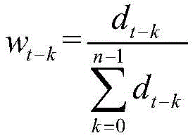
The embodiment of the invention provides an infrared touch screen line drawing processing method, which is characterized in that a sampling point C is determined according to the distance between sampling points t-(m-1) Weight w of (2) t-(m-1) May include:
according to
Determining sampling point C
t-k Weight w of (2)
t-k Wherein d
t-k For two adjacent sampling points C
t-k And C
t-(k+1) K=0, 1,2 …, n-1.
Determining sampling point C based on the distance between sampling points
t-(m-1) Weight w of (2)
t-(m-1) In the time, can be concretely based on
Determining sampling point C
t-k Weight w of (2)
t-k Wherein d
t-k For two adjacent sampling points C
t-k And C
t-(k+1) K=0, 1,2 …, n-1, i.e. determining the sampling point C
t Weight of +.>
(d
t For sampling point C
t And sampling point C
t-1 Distance of (C), sampling point C
t-1 Weight of +.>
(d
t-1 For sampling point C
t-1 And sampling point C
t-2 Distance) … … sample point C
t-(n-1) Weight of +.>
(d
t-(n-1) For sampling point C
t-(n-1) And sampling point C
t-n The distance of (2) and then the determined weight w may be used
t-(m-1) Carry in->
To obtain the coordinates of the contact point at the current moment.
The method for processing the line drawing of the infrared touch screen provided by the embodiment of the invention can further comprise the following steps after obtaining the image of the touch point motion according to the coordinates of the touch point:
and displaying the image by using an infrared touch screen.
After the image of the contact movement is obtained, the obtained image can be displayed by utilizing an infrared touch screen, so that a user can intuitively view the movement track of the contact.
The embodiment of the invention also provides an infrared touch screen line drawing processing device, referring to fig. 3, which shows a schematic structural diagram of the infrared touch screen line drawing processing device provided by the embodiment of the invention, and the device can comprise:
the coordinate acquisition module 11 is configured to obtain a contact point at a sampling point C when performing a line drawing operation on the infrared touch screen t-m Coordinates A at t-m Wherein t-m represents the first m times of the current time, m=n, n-1, …,1,0;
a first calculation module 12, configured to calculate a distance between two adjacent sampling points, and obtain a sum of distances between all the two adjacent sampling points;
a determining weight module 13 for comparing the distance sum with a preset threshold, and determining a sampling point C according to the angle of the sampling point if the distance sum is smaller than the preset threshold t-(m-1) Weight w of (2) t-(m-1) If the sum of the distances is greater than or equal to a preset threshold value, determining a sampling point C according to the distance between the sampling points t-(m-1) Weight w of (2) t-(m-1) Wherein, (m-1) is more than or equal to 0;
a
second calculation module 14 for utilizing
And obtaining the coordinates of the contact point at the current moment, and obtaining a corresponding image according to the coordinates of the contact point.
The device for processing the line drawing of the infrared touch screen provided by the embodiment of the invention, the determining weight module 14 may include:
a setting unit for setting the sampling point C t Is 90 °;
a calculation unit for calculating two adjacent sampling points C
t-i And C
t-(i+1) The included angle between the formed vector and the vector in the vertical direction
A first determining unit for according to
Determining sampling point C
t Weight w of (2)
t And according to
Determining sampling point C
t-(i+1) Weight w of (2)
t-(i+1) 。
The device for processing the line drawing of the infrared touch screen provided by the embodiment of the invention, the determining weight module 13 may include:
a second determining unit for according to
Determining sampling point C
t-k Weight w of (2)
t-k w
t-k Wherein d
t-k For two adjacent sampling points C
t-k And C
t-(k+1) K=0, 1,2 …, n-1.
The device for processing the line drawn by the infrared touch screen provided by the embodiment of the invention can further comprise:
and the display module is used for displaying the image by using the infrared touch screen after the image of the touch point motion is obtained according to the coordinates of the touch point.
The embodiment of the invention also provides an infrared touch screen line drawing processing device, referring to fig. 4, which shows a schematic structural diagram of the infrared touch screen line drawing processing device provided by the embodiment of the invention, and may include:
a memory 21 for storing a computer program;
a processor 22 for implementing any of the above-described infrared touch screen line drawing processing methods when executing a computer program.
The embodiment of the invention also provides a computer readable storage medium, wherein the computer readable storage medium is stored with a computer program, and the computer program realizes the steps of any of the infrared touch screen line drawing processing methods when being executed by a processor.
The description of the related parts in the device, the device and the computer readable storage medium for processing the line drawing on the infrared touch screen provided by the embodiment of the invention can be referred to the detailed description of the corresponding parts in the method for processing the line drawing on the infrared touch screen provided by the embodiment of the invention, and the detailed description is omitted herein.
It is noted that relational terms such as first and second, and the like are used solely to distinguish one entity or action from another entity or action without necessarily requiring or implying any actual such relationship or order between such entities or actions. Moreover, the terms "comprises," "comprising," or any other variation thereof, are intended to cover a non-exclusive inclusion, such that a process, method, article, or apparatus that comprises a list of elements is inherent to. Without further limitation, an element defined by the phrase "comprising one … …" does not exclude the presence of other like elements in a process, method, article, or apparatus that comprises the element. In addition, the parts of the above technical solutions provided in the embodiments of the present invention, which are consistent with the implementation principles of the corresponding technical solutions in the prior art, are not described in detail, so that redundant descriptions are avoided.
The previous description of the disclosed embodiments is provided to enable any person skilled in the art to make or use the present invention. Various modifications to these embodiments will be readily apparent to those skilled in the art, and the generic principles defined herein may be applied to other embodiments without departing from the spirit or scope of the invention. Thus, the present invention is not intended to be limited to the embodiments shown herein but is to be accorded the widest scope consistent with the principles and novel features disclosed herein.