CN110873087B - Cylinder with adjustable piston rod control position - Google Patents
Cylinder with adjustable piston rod control position Download PDFInfo
- Publication number
- CN110873087B CN110873087B CN201810998153.8A CN201810998153A CN110873087B CN 110873087 B CN110873087 B CN 110873087B CN 201810998153 A CN201810998153 A CN 201810998153A CN 110873087 B CN110873087 B CN 110873087B
- Authority
- CN
- China
- Prior art keywords
- piston rod
- loop bar
- piston
- cylinder body
- cylinder
- Prior art date
- Legal status (The legal status is an assumption and is not a legal conclusion. Google has not performed a legal analysis and makes no representation as to the accuracy of the status listed.)
- Active
Links
Images


Classifications
-
- F—MECHANICAL ENGINEERING; LIGHTING; HEATING; WEAPONS; BLASTING
- F15—FLUID-PRESSURE ACTUATORS; HYDRAULICS OR PNEUMATICS IN GENERAL
- F15B—SYSTEMS ACTING BY MEANS OF FLUIDS IN GENERAL; FLUID-PRESSURE ACTUATORS, e.g. SERVOMOTORS; DETAILS OF FLUID-PRESSURE SYSTEMS, NOT OTHERWISE PROVIDED FOR
- F15B15/00—Fluid-actuated devices for displacing a member from one position to another; Gearing associated therewith
- F15B15/08—Characterised by the construction of the motor unit
- F15B15/14—Characterised by the construction of the motor unit of the straight-cylinder type
- F15B15/1423—Component parts; Constructional details
-
- F—MECHANICAL ENGINEERING; LIGHTING; HEATING; WEAPONS; BLASTING
- F15—FLUID-PRESSURE ACTUATORS; HYDRAULICS OR PNEUMATICS IN GENERAL
- F15B—SYSTEMS ACTING BY MEANS OF FLUIDS IN GENERAL; FLUID-PRESSURE ACTUATORS, e.g. SERVOMOTORS; DETAILS OF FLUID-PRESSURE SYSTEMS, NOT OTHERWISE PROVIDED FOR
- F15B15/00—Fluid-actuated devices for displacing a member from one position to another; Gearing associated therewith
- F15B15/20—Other details, e.g. assembly with regulating devices
- F15B15/28—Means for indicating the position, e.g. end of stroke
- F15B15/2892—Means for indicating the position, e.g. end of stroke characterised by the attachment means
-
- F—MECHANICAL ENGINEERING; LIGHTING; HEATING; WEAPONS; BLASTING
- F15—FLUID-PRESSURE ACTUATORS; HYDRAULICS OR PNEUMATICS IN GENERAL
- F15B—SYSTEMS ACTING BY MEANS OF FLUIDS IN GENERAL; FLUID-PRESSURE ACTUATORS, e.g. SERVOMOTORS; DETAILS OF FLUID-PRESSURE SYSTEMS, NOT OTHERWISE PROVIDED FOR
- F15B2215/00—Fluid-actuated devices for displacing a member from one position to another
- F15B2215/30—Constructional details thereof
Abstract
The invention discloses a piston rod control position adjustable cylinder, which comprises a cylinder body, a piston and a piston rod, wherein the piston is movably arranged in the cylinder body, the piston also comprises a loop bar sleeved outside the piston rod, one end of the loop bar extends into the cylinder body and is in threaded connection with the piston, one end of the piston rod extends into the loop bar and is in limit fit with the piston, one side of the piston connected with the loop bar is provided with a convex sleeve between the loop bar and the piston rod, the peripheral wall of the convex sleeve is provided with an accommodating hole, a limit steel ball is arranged in the accommodating hole, one side of the loop bar extending into the cylinder body is provided with a counter bore, the bottom of the counter bore is provided with a guide inclined plane matched with the limit steel ball, and one side of the piston rod extending into the loop bar is provided with more than two limit annular grooves matched with the limit steel ball. The invention adjusts the extending end of the piston rod without being limited by the mounting structure of the air cylinder, and the adjusting of the control position of the piston rod can not change the stroke of the piston, and the invention has simple and reasonable structure and convenient operation.
Description
Technical Field
The invention belongs to the technical field of pneumatic elements, and particularly relates to a cylinder with an adjustable piston rod control position.
Background
The cylinder is a pneumatic element driven by an air source, and mainly comprises a cylinder body, a piston and a piston rod, wherein the piston linearly reciprocates in the cylinder body under the action of air source pressure so as to drive the piston rod to linearly reciprocate. Because the piston is fixedly connected with the piston rod, the control position of the piston rod of the air cylinder is generally not adjustable, however, some non-standard mechanical equipment requires the control position of the piston rod of the air cylinder to be correspondingly adjusted along with the change of the installation position of the execution part, so that the universal air cylinder with the adjustable control position of the piston rod is an important research subject in the pneumatic element industry.
The existing cylinder with the adjustable piston rod stroke is an adjusting cylinder with a double-head structure, namely, a piston rod extends out from one end of a cylinder body, an adjusting structure is arranged at the other end of the cylinder body and is used for adjusting the stroke of the piston rod, for example, the cylinder with the adjustable piston rod stroke position disclosed by patent publication No. CN204591868U is a double-head adjusting cylinder, the cylinder realizes the adjustment of the control position of the piston rod by adjusting the stroke of the piston in the cylinder body, although the purpose of adjusting the control position of the piston rod is achieved, the stroke of the linear reciprocating action of the piston rod is changed at the same time, and therefore, the cylinder can not be suitable for executing components with higher requirements on some control strokes, and in addition, the adjusting structure is positioned at one end of the piston rod of the cylinder body principle and is not beneficial to the installation of the cylinder body. In order to solve the problems in the prior art, the method can only be realized by adjusting the mounting position of the air cylinder, so that the operation is inconvenient, and the problems cannot be solved for mechanical equipment without reserving the adjustable mounting position of the air cylinder.
Disclosure of Invention
In view of the above-mentioned deficiencies of the prior art, the present invention provides a cylinder with adjustable piston rod control position, which realizes the adjustment of the control position of the piston rod without changing the control stroke of the piston rod by arranging an adjusting mechanism inside the cylinder body, and is convenient to operate.
In order to achieve the purpose, the invention adopts the technical scheme that:
a piston rod position-controlled adjustable cylinder comprises a cylinder body, a piston and a piston rod, wherein the piston is movably arranged in the cylinder body, the cylinder body is provided with an air inlet and an air outlet which are respectively communicated with cavities on two sides of the piston, the cylinder body further comprises a loop bar sleeved outside the piston rod, one end of the loop bar extends into the cylinder body and is in threaded connection with the piston, the other end of the loop bar extends out of the cylinder body, one end of the piston rod extends into the loop bar and is in limit fit with the piston, the other end of the piston rod extends out of the loop bar, one side, connected with the loop bar, of the piston is provided with a convex sleeve between the loop bar and the piston rod, the peripheral wall of the convex sleeve is provided with an accommodating hole, a limiting steel ball is arranged in the accommodating hole, one side, extending into the cylinder body, of the loop bar is provided with a counter bore, the bottom of the counter bore is provided with a guide inclined surface matched with the limiting steel ball, and one side, extending into the loop bar, is provided with more than two limiting ring grooves matched with the limiting steel ball; when the loop bar is screwed with the piston, the guide inclined plane of the loop bar clamps the limit steel ball in the limit ring groove of the piston rod, so that the piston, the loop bar and the piston rod are tightly connected into a whole; when the loop bar and the piston are unscrewed, the limiting steel balls can retreat into the counter bores of the loop bar, so that the piston rod can be adjusted in a telescopic way relative to the loop bar.
Furthermore, the piston is provided with a blind hole for the piston rod to extend into, a guide convex block is arranged in the blind hole along the extending direction of the piston rod, and the piston rod is provided with a guide groove in limit fit with the guide convex block.
Furthermore, a front end cover and a rear end cover are respectively arranged on two sides of the cylinder body, a convex ring which is concentric with the loop bar is arranged on the outer side of the front end cover, a sealing ring with a cross section in a shape like a Chinese character 'ren' is arranged between the convex ring and the loop bar in an overlapping mode, and a rotary cover which is abutted to the sealing ring is further in threaded connection with the front end cover.
Furthermore, one end of the loop bar extending out of the cylinder body is provided with a flat part, and the inner side of the flat part is provided with a bush in clearance fit with the piston rod.
Furthermore, the limiting ring groove comprises a first bevel edge and a second bevel edge which are matched with the limiting steel balls, and when the limiting steel balls are clamped in the limiting ring groove, the guide bevel, the first bevel edge and the second bevel edge are simultaneously abutted against the limiting steel balls.
Furthermore, the cross section of the containing holes is in a trapezoid shape with a wide outer part and a narrow inner part, the containing holes are multiple, and the multiple containing holes are uniformly distributed on the convex sleeve in a circumferential mode.
Furthermore, one side of the piston close to the sleeve rod is provided with a sealing gasket, and one end of the sleeve rod extending into the cylinder body is tightly abutted to the sealing gasket.
After adopting the technical scheme, compared with the prior art, the invention has the advantages that:
according to the piston rod position-controlled adjustable cylinder, a telescopic adjusting structure of a piston rod is arranged in a piston of a cylinder body, the piston rod is fixedly connected with the piston through the clamping fit of a limiting ring groove and a limiting steel ball, a loop rod is in threaded connection with the piston, and when the loop rod is screwed with the piston, the limiting steel ball is clamped in the limiting ring groove of the piston rod by a guide inclined surface of the loop rod, so that the piston, the loop rod and the piston rod are fixedly connected into a whole; when the loop bar and the piston are unscrewed, the limiting steel balls can retreat into the counter bore of the loop bar, the piston rod can axially move relative to the piston, the piston rod can be adjusted to stretch relative to the loop bar, and when the piston rod is adjusted in place, the loop bar is screwed, so that the piston, the loop bar and the piston rod can be fixedly connected into a whole. Compared with the existing air cylinder which adjusts the stroke of the piston rod to achieve the adjustment of the control position, the invention adjusts the extension end of the piston rod without being limited by the installation structure of the air cylinder, and the adjustment of the control position of the piston rod can not change the stroke of the piston, and has simple and reasonable structure and convenient operation.
Drawings
The invention is further illustrated with reference to the following figures and examples:
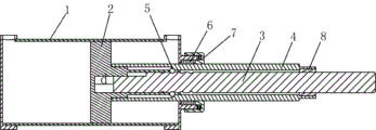
FIG. 1 is a schematic cross-sectional view of the present invention.
Fig. 2 is a schematic view of the structure of the piston rod of the present invention for adjusting the extension.
Fig. 3 is an enlarged schematic view of the structure shown at a in fig. 1.
Fig. 4 is a schematic perspective view of the present invention.
In the figure, 1, a cylinder body; 11. a front end cover; 12 a rear end cap; 2. a piston; 21. a convex sleeve; 22. a housing hole; 3. a piston rod; 31. a limiting ring groove; 31a, a first bevel; 31b. a second beveled edge; 4. a loop bar; 41. a counter bore; 42. a guide slope; 5. limiting steel balls; 6. a seal ring; 7. screwing a cover; 8. a bushing.
Detailed Description
The following description is only a preferred embodiment of the present invention, and does not limit the scope of the present invention.
Referring to fig. 1-4, a piston rod position-controlled adjustable cylinder comprises a cylinder body 1, a piston 2 and a piston rod 3, wherein the piston 2 is movably arranged in the cylinder body 1, the cylinder body 1 is provided with an air inlet and an air outlet which are respectively communicated with cavities on two sides of the piston 2, two sides of the cylinder body 1 are respectively provided with a front end cover 11 and a rear end cover 12, the air inlet is arranged on the rear end cover 12, and the air outlet is arranged on the front end cover 11.
Still locate the loop bar 4 outside the piston rod 3 including the cover, the one end of loop bar 4 stretches into in the cylinder body 1 and piston 2 threaded connection, and the other end of loop bar 4 stretches out outside front end housing 11, and the outside of front end housing 11 is equipped with the bulge loop that sets up with loop bar 4 concentric, overlaps between bulge loop and the loop bar 4 and is provided with the sealing washer 6 that the cross-section is "people" font, and it has spiral cover 7 that offsets with sealing washer 6 still to go back threaded connection on the front end housing 11. The loop bar 4 passes front end housing 11 and stretches out outside cylinder body 1, locates the sealing washer 6 in the convex ring and cooperates with loop bar 4 and plays sealed effect to 2 front side cavities of piston in the cylinder body 1, and the sealing washer 6 cross-section is "people" font, and adopts a plurality of sealing washers 6 to overlap the setting to lead to country's spiral cover 7 compresses tightly, is favorable to adjusting it after the sealing washer 6 wearing and tearing, in order to guarantee its sealing performance, increase of service life.
The one end of piston rod 3 stretches into in loop bar 4 with 2 spacing cooperations of piston, the other end of piston rod 3 stretches out outside loop bar 4, loop bar 4 is the hollow circle pole, loop bar 4 length is greater than 1 length of cylinder body, in order to ensure that its outer end stretches out in the front end housing 11 outside all the time, piston rod 3 is the solid circle pole, 3 length of piston rod are good at loop bar 4, when piston rod 3 inserts in loop bar 4, loop bar 4 is formed with the clearance between piston rod 3, in this embodiment, the piston rod 3 with loop bar 4 through connect into concentric setting with piston 2.
Specifically, the piston 2 is provided with a blind hole for the piston rod 3 to extend into, a guide convex block is arranged in the blind hole along the extending direction of the piston rod 3, and the piston rod 3 is provided with a guide groove in limit fit with the guide convex block. The piston rod 3 stretches into the blind hole of the piston 2, and is in limit fit with the guide groove through the guide convex block, so that the piston rod 3 can only stretch out and draw back relative to the piston 2 along the axial direction and cannot rotate relative to the piston. The blind hole in this setting and the piston 2 provides the headspace for piston rod 3 flexible regulation, and the location of accessible piston rod 3 makes loop bar 4 screw or loosen threaded connection relative to piston 2 simultaneously.
One side that piston 2 is connected with loop bar 4 is equipped with the convex cover 21 between loop bar 4 and piston rod 3, is equipped with on the perisporium of convex cover 21 and holds hole 22, and the cross-section that holds hole 22 is outer wide trapezoidal narrow inside, and it is a plurality of to hold hole 22, and these a plurality of holding holes 22 are the circumference and set up on convex cover 21 uniformly, hold the downthehole spacing steel ball 5 that is equipped with of hole 22, and in this embodiment, it is four respectively to hold hole 22 and spacing steel ball 5. The containing hole 22 with the cross section shape enables the spherical crown part of the limiting steel ball 5 to protrude out of the containing hole 22, a magnetic iron rod with the diameter equivalent to that of the piston rod 3 is used during assembly, the magnetic iron rod firstly extends into the convex sleeve 21 of the piston 2, then the limiting steel ball 5 is installed into the corresponding containing hole 22 through a jig, the limiting steel ball 5 is adsorbed in the containing hole 22 of the convex sleeve 21 under the magnetic force action of the magnetic rod, then the loop bar 4 is sleeved outside the magnetic rod and is in threaded connection with the piston 2, finally the magnetic rod is taken out and inserted into the piston rod 3, and the loop bar 4 is screwed to fix the piston 2, the loop bar 4 and the piston rod 3 into a whole.
One side of the loop bar 4 extending into the cylinder body 1 is provided with a counter bore 41, the bottom of the counter bore 41 is provided with a guide inclined plane 42 matched with the limiting steel ball 5, one side of the piston rod 3 extending into the loop bar 4 is provided with more than two limiting ring grooves 31 matched with the limiting steel ball 5, in the embodiment, the limiting ring grooves 31 are four, namely, the piston rod 3 is provided with four adjustable control positions; when the loop bar 4 is screwed with the piston 2, the guide inclined surface 42 of the loop bar 4 clamps the limit steel ball 5 in the limit ring groove 31 of the piston rod 3, so that the piston 2, the loop bar 4 and the piston rod 3 are tightly connected into a whole; when the loop bar 4 and the piston 2 are unscrewed, the limiting steel ball 5 can retreat into the counter bore 41 of the loop bar 4, so that the piston rod 3 can be adjusted in a telescopic way relative to the loop bar 4.
One end of the loop bar 4 extending out of the cylinder body 1 is provided with a flat part, and the inner side of the flat part is provided with a bush 8 which is in clearance fit with the piston rod 3. The flat part can be used for applying a rotating acting force to the loop bar 4, and the bush 8 positioned on the inner side of the flat part plays a role in positioning and supporting the piston rod 3 and the loop bar 4, so that the integral structure of the piston rod 3 and the loop bar 4 is more stable. The limiting ring groove 31 comprises a first inclined edge 31a and a second inclined edge 31b which are matched with the limiting steel balls 5, and when the limiting steel balls 5 are clamped in the limiting ring groove 31, the guide inclined surface 42, the first inclined edge 31a and the second inclined edge 31b are simultaneously abutted against the limiting steel balls 5. When the piston rod 3 is adjusted in a telescopic mode, the first inclined edge 31a and the second inclined edge 31b are abutted to the spherical surface of the limiting steel ball 5, so that the limiting steel ball 5 retreats into the counter bore 41 of the loop bar 4, and the piston rod 3 can be adjusted in a telescopic mode freely. One side of the piston 2 close to the loop bar 4 is provided with a sealing gasket, and one end of the loop bar 4 extending into the cylinder body 1 is tightly abutted to the sealing gasket. The sealing gasket is used for sealing the joint of the piston 2 and the sleeve rod 4 and simultaneously plays a role in buffering the sleeve rod 4.
The above description is only a preferred embodiment of the present invention, and all equivalent changes or modifications of the structure, characteristics and principles described in the present invention are included in the scope of the present invention.
Claims (7)
1. The utility model provides a cylinder with adjustable piston rod control position, includes cylinder body (1), piston (2) and piston rod (3), and piston (2) activity sets up in cylinder body (1), is equipped with respectively with inlet port and the exhaust hole of piston (2) both sides cavity intercommunication on cylinder body (1), its characterized in that: the piston cylinder is characterized by further comprising a loop bar (4) sleeved outside the piston rod (3), one end of the loop bar (4) extends into the cylinder body (1) to be in threaded connection with the piston (2), the other end of the loop bar (4) extends out of the cylinder body (1), one end of the piston rod (3) extends into the loop bar (4) to be in limit fit with the piston (2), the other end of the piston rod (3) extends out of the loop bar (4), one side, connected with the loop bar (4), of the piston (2) is provided with a convex sleeve (21) arranged between the loop bar (4) and the piston rod (3), the peripheral wall of the convex sleeve (21) is provided with an accommodating hole (22), a limiting steel ball (5) is arranged in the accommodating hole (22), one side, extending into the cylinder body (1), of the loop bar (4) is provided with a counter bore (41), the bottom of the counter bore (41) is provided with a guide inclined plane (42) matched with the limiting steel ball (5), and one side, extending into the loop bar (4), one side, extending into the piston rod (3), is provided with more than two limiting annular grooves (31) matched with the limiting steel ball (5); when the loop bar (4) is screwed with the piston (2), the guide inclined plane (42) of the loop bar (4) clamps the limit steel ball (5) in the limit ring groove (31) of the piston rod (3), so that the piston (2), the loop bar (4) and the piston rod (3) are fastened and connected into a whole; when the loop bar (4) and the piston (2) are unscrewed, the limiting steel ball (5) can retreat into the counter bore (41) of the loop bar (4) so as to enable the piston rod (3) to be adjusted in a telescopic mode relative to the loop bar (4).
2. The piston rod position adjustable cylinder of claim 1, wherein: the piston (2) is provided with a blind hole for the piston rod (3) to extend into, a guide convex block is arranged in the blind hole along the extending direction of the piston rod (3), and the piston rod (3) is provided with a guide groove in limit fit with the guide convex block.
3. The piston rod position adjustable cylinder of claim 1, wherein: a front end cover (11) and a rear end cover (12) are respectively arranged on two sides of the cylinder body (1), a convex ring which is concentric with the loop bar (4) is arranged on the outer side of the front end cover (11), a sealing ring (6) with a cross section in a herringbone shape is arranged between the convex ring and the loop bar (4) in an overlapping mode, and a rotary cover (7) which is abutted to the sealing ring (6) is further in threaded connection with the front end cover (11).
4. The piston rod position adjustable cylinder of claim 1, wherein: one end of the loop bar (4) extending out of the cylinder body (1) is provided with a flat part, and the inner side of the flat part is provided with a bush (8) which is in clearance fit with the piston rod (3).
5. The piston rod position adjustable cylinder of claim 1, wherein: spacing annular (31) include with spacing steel ball (5) matched with first hypotenuse (31 a) and second hypotenuse (31 b), when spacing steel ball (5) card was located in spacing annular (31), lead inclined plane (42), first hypotenuse (31 a) and second hypotenuse (31 b) and offset with spacing steel ball (5) simultaneously.
6. The piston rod position adjustable cylinder of claim 1, wherein: the section of the containing holes (22) is in a trapezoid shape with a wide outside and a narrow inside, the containing holes (22) are multiple, and the containing holes (22) are uniformly arranged on the convex sleeve (21) in a circumferential mode.
7. The piston rod position adjustable cylinder of claim 1, wherein: one side of the piston (2) close to the loop bar (4) is provided with a sealing gasket, and one end of the loop bar (4) extending into the cylinder body (1) is tightly abutted to the sealing gasket.
Priority Applications (1)
| Application Number | Priority Date | Filing Date | Title |
|---|---|---|---|
| CN201810998153.8A CN110873087B (en) | 2018-08-29 | 2018-08-29 | Cylinder with adjustable piston rod control position |
Applications Claiming Priority (1)
| Application Number | Priority Date | Filing Date | Title |
|---|---|---|---|
| CN201810998153.8A CN110873087B (en) | 2018-08-29 | 2018-08-29 | Cylinder with adjustable piston rod control position |
Publications (2)
| Publication Number | Publication Date |
|---|---|
| CN110873087A CN110873087A (en) | 2020-03-10 |
| CN110873087B true CN110873087B (en) | 2021-10-22 |
Family
ID=69714850
Family Applications (1)
| Application Number | Title | Priority Date | Filing Date |
|---|---|---|---|
| CN201810998153.8A Active CN110873087B (en) | 2018-08-29 | 2018-08-29 | Cylinder with adjustable piston rod control position |
Country Status (1)
| Country | Link |
|---|---|
| CN (1) | CN110873087B (en) |
Families Citing this family (1)
| Publication number | Priority date | Publication date | Assignee | Title |
|---|---|---|---|---|
| CN113187776B (en) * | 2021-05-26 | 2024-03-29 | 宁波市鑫潮自动化元件有限公司 | Variable stroke cylinder |
Citations (8)
| Publication number | Priority date | Publication date | Assignee | Title |
|---|---|---|---|---|
| FR2225641A1 (en) * | 1973-04-16 | 1974-11-08 | Rmi Rhein Main Ind Gmbh Co | |
| CN2088178U (en) * | 1991-02-25 | 1991-11-06 | 林美森 | Position-locking device of telescope rod |
| CN202493517U (en) * | 2012-03-26 | 2012-10-17 | 徐州重型机械有限公司 | Hydraulic oil cylinder |
| CN103452944A (en) * | 2013-08-23 | 2013-12-18 | 浙江亿太诺气动科技有限公司 | Vehicle-carried single-acting cylinder |
| CN105047446A (en) * | 2015-06-29 | 2015-11-11 | 平高集团有限公司 | Hydraulic buffer and breaker operating mechanism using same |
| CN205136209U (en) * | 2015-11-15 | 2016-04-06 | 内蒙古北方重工业集团有限公司 | Hydraulic cylinder piston rod uses removable screwed joint |
| CN205416318U (en) * | 2016-03-26 | 2016-08-03 | 深圳永宁现代包装实业有限公司 | Screw rod adjustment mechanism of make -up machine |
| CN207363998U (en) * | 2017-10-17 | 2018-05-15 | 佳木斯常发佳联农业装备有限公司 | A kind of lifting cylinder, lifting cylinder and harvester applied to harvester reel |
Family Cites Families (6)
| Publication number | Priority date | Publication date | Assignee | Title |
|---|---|---|---|---|
| CA1088848A (en) * | 1977-05-26 | 1980-11-04 | Karl H. Wallischeck | Jam proof piston |
| DE20116300U1 (en) * | 2001-10-01 | 2002-02-07 | Reiss Bueromoebel Gmbh | Adjustable column |
| CN101825125A (en) * | 2009-03-06 | 2010-09-08 | 张家港和升数控机床制造有限公司 | Oil cylinder with adjustable piston stroke |
| CN203847468U (en) * | 2014-03-31 | 2014-09-24 | 长治清华机械厂 | Stepped steel ball locking hydraulic cylinder |
| CN204828221U (en) * | 2015-07-28 | 2015-12-02 | 博峰汽配科技有限公司 | But flexible bolt assembly of axial |
| CN206054436U (en) * | 2016-08-31 | 2017-03-29 | 奉化市鑫潮自动化元件有限公司 | A kind of stroke adjustable dual-head cylinder |
-
2018
- 2018-08-29 CN CN201810998153.8A patent/CN110873087B/en active Active
Patent Citations (8)
| Publication number | Priority date | Publication date | Assignee | Title |
|---|---|---|---|---|
| FR2225641A1 (en) * | 1973-04-16 | 1974-11-08 | Rmi Rhein Main Ind Gmbh Co | |
| CN2088178U (en) * | 1991-02-25 | 1991-11-06 | 林美森 | Position-locking device of telescope rod |
| CN202493517U (en) * | 2012-03-26 | 2012-10-17 | 徐州重型机械有限公司 | Hydraulic oil cylinder |
| CN103452944A (en) * | 2013-08-23 | 2013-12-18 | 浙江亿太诺气动科技有限公司 | Vehicle-carried single-acting cylinder |
| CN105047446A (en) * | 2015-06-29 | 2015-11-11 | 平高集团有限公司 | Hydraulic buffer and breaker operating mechanism using same |
| CN205136209U (en) * | 2015-11-15 | 2016-04-06 | 内蒙古北方重工业集团有限公司 | Hydraulic cylinder piston rod uses removable screwed joint |
| CN205416318U (en) * | 2016-03-26 | 2016-08-03 | 深圳永宁现代包装实业有限公司 | Screw rod adjustment mechanism of make -up machine |
| CN207363998U (en) * | 2017-10-17 | 2018-05-15 | 佳木斯常发佳联农业装备有限公司 | A kind of lifting cylinder, lifting cylinder and harvester applied to harvester reel |
Also Published As
| Publication number | Publication date |
|---|---|
| CN110873087A (en) | 2020-03-10 |
Similar Documents
| Publication | Publication Date | Title |
|---|---|---|
| CN202140369U (en) | Single-acting cylinder | |
| CN110873087B (en) | Cylinder with adjustable piston rod control position | |
| CN206035755U (en) | Vacuum pump for appearance is taked care of to negative pressure of piston structure | |
| CN110848203A (en) | Guide sleeve for hydraulic cylinder | |
| CN201166080Y (en) | Stroke connection size constant pressure adjustable gas spring | |
| CN105972246B (en) | A kind of novel manual diaphragm valve | |
| CN105108700B (en) | Assembling tool of valve guide pipe | |
| CN110095229B (en) | Engine leakage test orifice end face plugging mechanism | |
| CN212616479U (en) | Ball valve rod structure | |
| CN220302460U (en) | Telescopic adjusting guide sleeve | |
| CN214063288U (en) | Screw compressor sealing ring | |
| CN217518816U (en) | Connecting rod piston device of air compressor or vacuum pump | |
| CN214534759U (en) | Hydraulic oil cylinder guide sleeve with built-in reversing valve | |
| CN208764034U (en) | A kind of embedded threaded guide sleeve structure | |
| CN215148617U (en) | Mounting fixture for sealing element of cylinder piston | |
| CN212887216U (en) | Roller assembly | |
| CN215719916U (en) | Oil cylinder structure capable of being connected in series | |
| CN210343054U (en) | Pneumatic outer pendulum driving pump body | |
| CN216882085U (en) | Slab deburring device | |
| CN214838377U (en) | But aligning seal structure | |
| CN214837485U (en) | Two guide cylinder that go out pole | |
| CN204877865U (en) | Energy -conserving no oily vertical vacuum pump | |
| CN216382059U (en) | Hydraulic cylinder with adjustable stroke | |
| CN218093713U (en) | Improved corner cylinder | |
| CN207788869U (en) | Three-in-one pneumatic handheld tool |
Legal Events
| Date | Code | Title | Description |
|---|---|---|---|
| PB01 | Publication | ||
| PB01 | Publication | ||
| SE01 | Entry into force of request for substantive examination | ||
| SE01 | Entry into force of request for substantive examination | ||
| GR01 | Patent grant | ||
| GR01 | Patent grant |