CN110865480A - Image depth modulation module and application thereof - Google Patents
Image depth modulation module and application thereof Download PDFInfo
- Publication number
- CN110865480A CN110865480A CN201810980453.3A CN201810980453A CN110865480A CN 110865480 A CN110865480 A CN 110865480A CN 201810980453 A CN201810980453 A CN 201810980453A CN 110865480 A CN110865480 A CN 110865480A
- Authority
- CN
- China
- Prior art keywords
- image
- module
- electric control
- light
- depth
- Prior art date
- Legal status (The legal status is an assumption and is not a legal conclusion. Google has not performed a legal analysis and makes no representation as to the accuracy of the status listed.)
- Pending
Links
Images


Classifications
-
- G—PHYSICS
- G02—OPTICS
- G02F—OPTICAL DEVICES OR ARRANGEMENTS FOR THE CONTROL OF LIGHT BY MODIFICATION OF THE OPTICAL PROPERTIES OF THE MEDIA OF THE ELEMENTS INVOLVED THEREIN; NON-LINEAR OPTICS; FREQUENCY-CHANGING OF LIGHT; OPTICAL LOGIC ELEMENTS; OPTICAL ANALOGUE/DIGITAL CONVERTERS
- G02F1/00—Devices or arrangements for the control of the intensity, colour, phase, polarisation or direction of light arriving from an independent light source, e.g. switching, gating or modulating; Non-linear optics
- G02F1/01—Devices or arrangements for the control of the intensity, colour, phase, polarisation or direction of light arriving from an independent light source, e.g. switching, gating or modulating; Non-linear optics for the control of the intensity, phase, polarisation or colour
- G02F1/13—Devices or arrangements for the control of the intensity, colour, phase, polarisation or direction of light arriving from an independent light source, e.g. switching, gating or modulating; Non-linear optics for the control of the intensity, phase, polarisation or colour based on liquid crystals, e.g. single liquid crystal display cells
- G02F1/133—Constructional arrangements; Operation of liquid crystal cells; Circuit arrangements
- G02F1/1333—Constructional arrangements; Manufacturing methods
- G02F1/1334—Constructional arrangements; Manufacturing methods based on polymer dispersed liquid crystals, e.g. microencapsulated liquid crystals
-
- G—PHYSICS
- G02—OPTICS
- G02B—OPTICAL ELEMENTS, SYSTEMS OR APPARATUS
- G02B27/00—Optical systems or apparatus not provided for by any of the groups G02B1/00 - G02B26/00, G02B30/00
- G02B27/01—Head-up displays
- G02B27/017—Head mounted
- G02B27/0172—Head mounted characterised by optical features
-
- Y—GENERAL TAGGING OF NEW TECHNOLOGICAL DEVELOPMENTS; GENERAL TAGGING OF CROSS-SECTIONAL TECHNOLOGIES SPANNING OVER SEVERAL SECTIONS OF THE IPC; TECHNICAL SUBJECTS COVERED BY FORMER USPC CROSS-REFERENCE ART COLLECTIONS [XRACs] AND DIGESTS
- Y02—TECHNOLOGIES OR APPLICATIONS FOR MITIGATION OR ADAPTATION AGAINST CLIMATE CHANGE
- Y02B—CLIMATE CHANGE MITIGATION TECHNOLOGIES RELATED TO BUILDINGS, e.g. HOUSING, HOUSE APPLIANCES OR RELATED END-USER APPLICATIONS
- Y02B20/00—Energy efficient lighting technologies, e.g. halogen lamps or gas discharge lamps
- Y02B20/40—Control techniques providing energy savings, e.g. smart controller or presence detection
Abstract
The invention discloses an image depth modulation module, which comprises a plurality of layers of electric control light modulation plates which are stacked, wherein each layer of electric control light modulation plate is composed of a plurality of electric control light modulation units, each electric control light modulation unit is provided with an independent switch, and each electric control light modulation unit can be regulated and controlled to be in a transmission state or a scattering state. Meanwhile, the invention also discloses a display module and a near-eye display device applying the image depth modulation module, which load depth of field for the image through a physical structure, realize the adjustment of the depth of field at a pixel level or a quasi-pixel level, solve the convergence conflict effect of vision, enable the image observed by human eyes to better accord with the focusing habit of human eyes, and enable the depth arrangement of the displayed image to be closer to the depth rule of a real light field.
Description
Technical Field
The invention relates to the field of image display, in particular to an image depth modulation module, a near-eye display optical module using the image depth modulation module and near-eye display equipment.
Background
Most of the existing HMD (head mounted display) virtual reality/augmented reality display systems are designed according to a fixed imaging distance, so that the distance between a virtual image displayed in front of human eyes and the human eyes after an image source passes through the optical display system is fixed, and the display without image depth causes a Vergence Accommodation Conflict (VAC) to cause motion sickness, and the user experience is very poor. And if such an HMD apparatus is used for augmented reality applications, since the distance of the virtual image from the human eye is constant and the environment is constantly changed, the virtual image seen through these display systems is floating in the air, and is separated from the actual environment, and a true augmented display effect cannot be achieved.
Disclosure of Invention
The invention aims to provide an image depth modulation module, a near-eye display optical module and a near-eye display device using the image depth modulation module, which are used for realizing image display with depth of field and solving the problem of convergence conflict of the vision of the near-eye display device.
In order to achieve the above object, the present invention provides an image depth modulation module, which includes a plurality of stacked electrically controlled light modulation panels, each electrically controlled light modulation panel is composed of a plurality of electrically controlled light modulation units, each electrically controlled light modulation unit has an independent switch, and each electrically controlled light modulation unit can be controlled to be in a transmission state or a scattering state.
Preferably, the electrically controlled dimming unit is a polymer-stabilized liquid crystal photoelectric unit or a polymer-dispersed liquid crystal photoelectric unit.
Preferably, the multiple layers of electrically controlled light adjusting plates are arranged in parallel at intervals.
Correspondingly, the invention also provides a display module which comprises an image generating module, an image depth modulation module and an objective system, wherein the image depth modulation module is the image depth modulation module, and image light generated by the image generating module firstly passes through the image depth modulation module and then is emitted out through the objective system.
Preferably, each of the electrically controlled dimming units on each of the electrically controlled dimming panels corresponds to one or more pixels generated by the image generation module.
Preferably, the image depth modulation module comprises 12 layers of electrically controlled light modulation plates which are arranged in a stacked manner.
Preferably, the imaging distance P of each layer of the electrically controlled light modulation panelnThe design is as follows:

wherein, L is the diameter of a pupil of a human eye, epsilon represents the resolution of the human eye, n is the layer number of the electric control light adjusting plate, and when n is 1, the electric control light adjusting plate represents the first layer nearest to the objective lens system.
Preferably,. epsilon.ranges from 1 'to 3' and L ranges from 2mm to 5 mm.
Preferably,. epsilon.is 2' and L is 3.5 mm.
Preferably, the scattering angle of each of the electrically controlled dimming units is less than 60 ° and greater than 5 °.
Correspondingly, the invention also provides near-eye display equipment which comprises one group or two groups of near-eye display optical systems, wherein each group of near-eye display optical systems comprises one group of display module and a light guide system, the image light generated by the image generation module firstly passes through the image depth modulation module, then enters the light guide system through the objective lens system, and is emitted to human eyes through the light guide system.
Preferably, the near-eye display device further includes a processor, and the processor controls the image generation module to generate the image light, and controls the image depth modulation module to control each of the electrically controlled dimming units in each layer of the electrically controlled dimming panel to adjust to a transmission state or a scattering state according to different depths of field corresponding to different regions of the image light.
Wherein, controlling the image depth modulation module according to the different depth of field that the different regions of image light correspond, every automatically controlled dimming unit adjustment is transmission state or scattering state in every layer of automatically controlled dimming board of control, specifically does:
and controlling the electric control dimming units of the corresponding areas of the electric control dimming plates corresponding to the depth of field of the image light in a certain area to be adjusted to be in a scattering state, and adjusting the electric control dimming units of the corresponding areas of the electric control dimming plates on other layers which are stacked to be in a transmission state.
Compared with the prior art, the invention has the following beneficial effects:
according to the embodiment of the invention, the depth of field is loaded to the image through the physical structure, so that the pixel-level or quasi-pixel-level depth of field adjustment is realized, the convergence conflict effect of vision can be solved, the image observed by human eyes is more in line with the focusing habit of the human eyes, and the depth arrangement of the displayed image is closer to the depth rule of a real light field.
Drawings
In order to more clearly illustrate the embodiments of the present invention or the technical solutions in the prior art, the drawings used in the description of the embodiments or the prior art will be briefly described below, it is obvious that the drawings in the following description are only some embodiments of the present invention, and for those skilled in the art, other drawings can be obtained according to the drawings without inventive exercise:
FIG. 1 is a schematic diagram of an image depth modulation module according to an embodiment of the present invention;
fig. 2 is a schematic structural view of each layer of the electrically controlled light modulation panel in fig. 1;
FIG. 3 is a schematic structural diagram of a display module according to an embodiment of the invention;
FIG. 4 is a schematic structural diagram of a display module according to an embodiment of the invention;
FIG. 5 is a schematic diagram of the image generation module generating a landscape image according to the embodiment of the present invention;
FIG. 6 is a schematic diagram of a near-eye display optical system of a near-eye display device according to an embodiment of the present invention;
fig. 7 is a schematic structural diagram of a near-eye display device according to an embodiment of the present invention.
Detailed Description
The technical solutions in the embodiments of the present invention will be clearly and completely described below with reference to the drawings in the embodiments of the present invention, and it is obvious that the described embodiments are only a part of the embodiments of the present invention, and not all of the embodiments. All other embodiments, which can be derived by a person skilled in the art from the embodiments given herein without making any creative effort, shall fall within the protection scope of the present invention.
Referring to fig. 1, which is a schematic structural diagram of an image depth modulation module according to an embodiment of the present invention, the image depth modulation module according to the embodiment of the present invention includes a plurality of stacked electrically controlled light modulation panels 10, each electrically controlled light modulation panel 10 includes a plurality of electrically controlled light modulation units 101, and a schematic structural diagram of each electrically controlled light modulation panel 10 is as shown in fig. 2, each electrically controlled light modulation unit 101 has an independent switch, the switch may be a transparent or semi-transparent semiconductor switch, and each electrically controlled light modulation unit may be controlled to be in a transmission state or a scattering state.
An image is incident from one side of the image depth modulation module, a first part of the image passes through a first area of a layer of electric control light modulation plate 10, and each electric control light modulation unit on the electric control light modulation plate can be independently controlled, so that the electric control light modulation unit in the first area can be controlled to be in a scattering state, the first part of the image is scattered in the first area of the electric control light modulation plate, and at the moment, the first part of the image is loaded with depth information; the second part of the image passes through a second area on another electric control light modulation plate and is scattered, and the second part of the image is loaded with another depth information; by analogy, each electronic control light modulation board can be responsible for one depth, and finally, multiple depth information can be loaded on the image. When the size of each of the electrically controlled dimming cells 101 constituting the electrically controlled dimming panel 10 is made sufficiently small, depth modulation at a pixel or quasi-pixel level can be realized.
Preferably, the electrically controlled dimming unit may be selected from polymer stabilized liquid crystal electro-optic cells PSLC (polymerized liquid crystal cell) or inverse PSLC, or may be selected from electro-optic cells with the same physical properties, such as polymer dispersed liquid crystal electro-optic cells pdlc (polymerized liquid crystal cell), and the electrically controlled dimming unit is switched to a transmissive state or a scattering state by applying or not applying a voltage. Taking an electrically controlled dimming unit as PSLC as an example: the electrode for controlling the PSLC can select TFT (thin Film transistor) or ITO (indium tin oxide) and other similar technologies, and is made into a display screen similar to a TFT (thin Film transistor), except that each liquid crystal pixel in the TFT replaces the PSLC with the size of a pixel level, so that each PSLC can be controlled by a semiconductor switch at a corresponding position and is generally controlled by an electric pulse; each PSLC can be independently controlled by the semiconductor switch at its corresponding position. For example, the parameters of a PSLC electrically controlled light modulation panel may be designed to have a size of 3 × 4.5mm, a resolution of 640 × 540, and a thickness of 10um to 30um, and the size of each PSLC constituting the PSLC electrically controlled light modulation panel is made small enough, for example, the size of one PSLC is made to be a square with a side of 10 μm, so that the corresponding portions of two different depths of the incident image can be fitted to each other more smoothly.
In order to make the depth modulation of the whole image picture uniform, preferably, the multiple layers of electrically controlled light modulation panels are arranged in parallel at intervals, and the interval distance between adjacent electrically controlled light modulation panels needs to be designed into different intervals according to different preset focusing distances, whether the electrically controlled light modulation panels are used in cooperation with other amplifying optical elements or not, and the like, and is not limited herein.
Referring to fig. 3, which is a schematic structural diagram of a display module according to an embodiment of the present invention, a near-eye display optical module according to an embodiment of the present invention includes an image generation module 2, an image depth modulation module 1, and an objective lens system 3, where the image depth modulation module 1 is the image depth modulation module described in the foregoing embodiment, the image generation module 2 generates collimated image light, and the collimated image light is loaded with depth information by the image depth modulation module 1 and then is emitted by the objective lens system 3. In the embodiment of the invention, each electric control dimming unit on each layer of electric control dimming plate can be designed to correspond to one or more pixel points generated by the image generation module, and when each electric control dimming unit is designed to correspond to one pixel point generated by the image generation module, pixel-level depth modulation is realized.
In fig. 3, the image depth modulation module 1 is forward scattering, and in practical implementation, the image generation module 2 may also be disposed on the other side of the image depth modulation module 1 in the manner of fig. 4, and implemented in a backward scattering manner.
According to the embodiment of the invention, the depth of field is loaded to the image through the physical structure, so that the convergence conflict effect can be solved, the image observed by human eyes is more in line with the focusing habit of the human eyes, and the depth arrangement of the displayed image is closer to the depth rule of a real light field. Since human eyes are generally sensitive to depth of 12 layers, the image depth modulation module formed by the 12 layers of electrically controlled light modulation panels is the best, and certainly, if the size and weight of the near-eye display optical module are reduced, 3, 4, 5, 6, 7, 8 layers and the like can be selected, and the effect of depth of field is also achieved, but the effect cannot reach the nature of 12 layers.
In the following, how the depth of field is realized by the display module according to the present invention is described with reference to fig. 5, assuming that the electrically controlled dimming unit is a PSLC, as shown in fig. 5, a landscape image is generated for the image generation module, the landscape image is incident from one side of the image depth modulation module, and the image area of the tree and the image area of the mountain have different depths. For example: the image area of the tree is taken charge of by a first layer of electric control light adjusting plate of the image depth modulation module, a plurality of PSLCs irradiated by the image area of the tree on the first layer of electric control light adjusting plate are controlled to be in a scattering state, the display position of the tree is positioned at the position of the first layer of electric control light adjusting plate, namely the focusing position is positioned at the position of the first layer of electric control light adjusting plate, the PSLCs of other areas on the first layer of electric control light adjusting plate are controlled to be in a transmission state, and the PSLCs of the projection areas of the scattering state PSLCs on the first layer of electric control light adjusting plate on the other layers of electric control light; the image area of the mountain is taken charge of by a second layer of electric control light adjusting plate of the image depth modulation module, a plurality of PSLCs irradiated by the image area of the mountain on the second layer of electric control light adjusting plate are controlled to be in a scattering state, the display position of the mountain is positioned at the position of the second layer of electric control light adjusting plate, namely the focusing position is positioned at the position of the second layer of electric control light adjusting plate, the PSLCs of other areas on the second layer of electric control light adjusting plate are controlled to be in a transmission state, and the PSLCs of the projection areas of the scattering state PSLCs on the second layer of electric control light adjusting plate on the other layers of electric control light adjusting plate are also controlled to be; by analogy, the image parts of other depths of the landscape image are all displayed on a certain layer of the electric control light adjusting plate. Due to the focusing characteristic of human eyes, when human eyes focus on a certain layer of electric control light adjusting plate, other layers of electric control light adjusting plates can be in a fuzzy image in human eyes so as to realize the effect of depth of field. As long as the size of each PSLC is small enough, the five depth images corresponding to the first depth area to the fifth depth area are more smoothly connected with each other.
The previous paragraph describes how the multilayer electrically controlled light adjusting plate can realize the depth of field, and the following introduces how to design the image focusing position of each layer of electrically controlled light adjusting plate to better solve the visual convergence conflict and better simulate the real light field on the basis of the previous paragraph.
In the following, we simply calculate the depth of field of human eyes, the resolution of human eyes is represented by epsilon, and the pupil diameter is L. When the human eyes are adjustedWhen the focal distance is P, the long shot is P1And close shot P2The distance of (a) is:


using diopter Representing, the focus, distance and near positions can be represented as:


the corresponding depth of field may be expressed in diopters as:
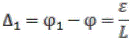


it can be seen that when depth of field is expressed in diopters, which is related only to the human eye resolution epsilon and the pupil diameter L, the human eye depth of field Δ is calculated. The focusing range of a human eye is generally 0.25m to infinity, expressed in diopters as 0-4L. Therefore, in the process of designing the waveguide, if we need n layers of electricityThe light control and adjustment plate is used for meeting the imaging requirement, and the imaging distance P of each layer of the light control and adjustment platenAccording to the focusing formula, the focusing formula can be expressed as:

wherein, L is the diameter of the pupil, epsilon represents the resolution of the human eye, n is the layer number of the electric control light modulation plate, and when n is 1, the electric control light modulation plate represents the first layer nearest to the objective lens system. The imaging distance of the first layer of the electric control light modulation plate is n equal to 1, the imaging distance of the second layer of the electric control light modulation plate is n equal to 2, and the imaging distances of other layers of the electric control light modulation plates can be calculated in sequence. The imaging distance of each layer of the electric control light adjusting plate obtained according to the formula can enable human eyes to see clear images at any focal length in space, and finally full-space imaging is met. In this paragraph, the imaging distance may be set by, but is not limited to, the following two ways: firstly, the imaging distances of different electric control light adjusting plates can be realized through focusing modes such as a lens and the like; second, the position of the electrically controlled light modulation panels can be set, and the imaging distance of each electrically controlled light modulation panel is located at its own position. Considering that the second scheme is too large in size and low in practicability in actual implementation, generally, the imaging distances of different electronic control light adjusting plates can be realized by adopting focusing modes such as lenses, for example, the lens 3 in fig. 3 is adopted, and the lens simultaneously realizes the amplification of the distance and the image, so that the physical distance between the electronic control light adjusting plates can be compressed in proportion, and the miniaturization of the module is realized.
The resolution epsilon of the human eye is typically 1 'to 3' and the pupil diameter L is 2mm-5 mm. In the following we take the example of a resolution epsilon of 2' and a pupil diameter L of 3.5mm, according to the following formula:

the resolution epsilon expressed by the angle needs to be converted into radian for calculation during calculation, the depth of field delta obtained by calculation is 0.3323L, the focusing range of human eyes is 0.25m to infinity, and the depth of field is expressed by diopter to be 0-4L. Therefore, in the process of designing the image depth modulation module, if 12 layers of electric control light modulation plates are needed to meet the imaging requirement, the focusing distance corresponding to each electric control light modulation plate is as follows: 0.2608m, 0.2856m, 0.3155m, 0.3525m, 0.3992m, 0.4603m, 0.5434m, 0.6632m, 0.8507m, 1.1860m, 1.9573m and 5.5991 m. Due to the pupil diameter and the angular resolution of the human eye, each plane has a depth of field range for the human eye, and the 12 planes can connect the depth of field ranges, so that the human eye can clearly image at any position in space. The full-space imaging can be met, and the focusing of human eyes at any position can be realized by a focal plane which can be clearly imaged.
In the embodiment of the present invention, in order to prevent the scattered light of a certain light modulation panel from affecting the light modulation panel arranged behind, the scattering angle of each of the electrically controlled light modulation units is preferably less than 60 ° and greater than 5 °. For example, a certain position of an image is scattered by the third electrically controlled dimming unit of the second dimming panel, light scattered by the third electrically controlled dimming unit of the second dimming panel enters the third dimming panel, and is scattered by the electrically controlled dimming unit of the third dimming panel outside the projection plane of the third electrically controlled dimming unit on the second dimming panel, so that the position of the image is scattered by the plurality of dimming panels to cause interference. The smaller the scattering angle is, the smaller the interference degree is, but if the scattering angle is less than-5 degrees, the difference between the imaging depths of field of the two light adjusting plates is too small, so that the human eyes are difficult to distinguish the depths of field of different light adjusting plates, and the depth modulation effect is not good enough.
The display module in the above embodiment can be applied to near-to-eye display equipment, such as virtual reality VR equipment or augmented reality AR equipment, and can also be applied to rear projection display equipment, such as a television, an advertisement screen, and the like. Taking near-eye display equipment as an example, the near-eye display equipment includes one group or two groups of near-eye display optical systems, each group of near-eye display optical systems includes one group of display module and light guide system in the embodiment of the present invention, as shown in fig. 6, which is a schematic structural diagram of the near-eye display optical system, image light generated by the image generation module in the display module 400 firstly passes through the image depth modulation module, then exits through the objective lens system, is coupled into the light guide system 5 through the coupling system 4, and exits to human eyes through the light guide system 5. Referring to fig. 7, the display module 400 may be designed on both sides of the frame or on the temple, and the waveguide system 5 may be designed as a lens.
During the concrete implementation, near-to-eye display device still includes the treater, and the treater is controlled the image and is produced the module and produce image light, controls the image depth modulation module according to the different depth of field that image light different regions correspond, controls in every layer of automatically controlled light modulation board every automatically controlled unit adjustment of adjusting to transmission state or scattering state, specifically is:
and controlling the electric control dimming units of the corresponding areas of the electric control dimming plates corresponding to the depth of field of the image light in a certain area to be adjusted to be in a scattering state, and adjusting the electric control dimming units of the corresponding areas of the electric control dimming plates on other layers which are stacked to be in a transmission state. Similarly, as illustrated in fig. 4, for example, as for the image in fig. 4, if the electric control light modulation panel corresponding to the depth of field corresponding to the tree is assumed to be the first layer of electric control light modulation panel, and the electric control light modulation panel corresponding to the depth of field corresponding to the mountain is assumed to be the second layer of electric control light modulation panel, the plurality of electric control light modulation units irradiated by the image area of the tree on the first layer of electric control light modulation panel are controlled to be in the scattering state, and the electric control light modulation units of the projection area of the electric control light modulation unit in the scattering state on the first layer of electric control light modulation panel on the other layer of; the plurality of electronic control dimming units irradiated by the mountain image area on the second layer of electronic control dimming board are controlled to be in a scattering state, and the electronic control dimming units of the projection areas of the scattering state electronic control dimming units on the second layer of electronic control dimming board on other layers of electronic control dimming boards are also controlled to be in a transmission state.
The invention adopts the multilayer electric control light adjusting plate to realize the depth of field effect by a physical method, so that the image seen by human eyes more conforms to the rule of a real light field; in addition, the reasonable design of the imaging distance of the multilayer electric control light adjusting plate can better accord with the law of a real space light field, so that the focusing of human eyes is more natural and closer to the focusing mode in the real space light field, and the human eyes are more comfortable. Finally, the discomfort of dizziness and eye distension in VR and AR display in the prior art is effectively solved through the two points.
All of the features disclosed in this specification, or all of the steps in any method or process so disclosed, may be combined in any combination, except combinations of features and/or steps that are mutually exclusive.
Any feature disclosed in this specification (including any accompanying claims, abstract and drawings), may be replaced by alternative features serving equivalent or similar purposes, unless expressly stated otherwise. That is, unless expressly stated otherwise, each feature is only an example of a generic series of equivalent or similar features.
The invention is not limited to the foregoing embodiments. The invention extends to any novel feature or any novel combination of features disclosed in this specification and any novel method or process steps or any novel combination of features disclosed.
Claims (13)
1. The utility model provides an image depth modulation module which characterized in that, includes the automatically controlled board of adjusting luminance of the multilayer that piles up the setting, and every layer of automatically controlled board of adjusting luminance comprises a plurality of automatically controlled light modulation units, and every automatically controlled light modulation unit has independent switch, and every automatically controlled light modulation unit can be regulated and control to transmission state or scattering state.
2. The image depth modulation module of claim 1, wherein the electrically controlled dimming cell is a polymer stabilized liquid crystal cell or a polymer dispersed liquid crystal cell.
3. The image depth modulation module of claim 2, wherein the plurality of electrically controlled light modulation panels are spaced apart in parallel.
4. A display module comprising an image generation module, an image depth modulation module and an objective system, wherein the image depth modulation module is the image depth modulation module of any one of claims 1 to 3, and image light generated by the image generation module passes through the image depth modulation module and then exits through the objective system.
5. The display module as claimed in claim 4, wherein each of the electrically controlled dimming units of each of the layers corresponds to one or more pixels generated by the image generating module.
6. The display module of claim 5, wherein the image depth modulation module comprises 12 layers of electrically controlled light modulation panels arranged in a stack.
7. The display module according to any one of claims 4 to 6, wherein the imaging distance P of each layer of the electrically controlled light modulation panelnThe design is as follows:

wherein, L is the diameter of a pupil of a human eye, epsilon represents the resolution of the human eye, n is the layer number of the electric control light adjusting plate, and when n is 1, the electric control light adjusting plate represents the first layer nearest to the objective lens system.
8. The display module of claim 7, wherein ε ranges from 1 'to 3' and L ranges from 2mm to 5 mm.
9. The display module of claim 7, wherein ε is 2' and L is 3.5 mm.
10. The display module according to any one of claims 4 to 6, wherein the scattering angle of each of the electrically controlled dimming cells is less than 60 ° and greater than 5 °.
11. A near-eye display device comprising one or two sets of near-eye display optical systems, wherein each set of near-eye display optical system comprises a set of display module and light guide system as claimed in any one of claims 4 to 10, the image light generated by the image generation module passes through the image depth modulation module, then enters the light guide system through the objective system, and exits from the light guide system to human eyes.
12. The near-eye display device of claim 11, wherein the processor controls the image generation module to generate the image light and controls the image depth modulation module to control each of the electrically controlled dimming units in each of the layers of electrically controlled dimming panels to adjust to a transmissive state or a scattering state according to different depths of field corresponding to different regions of the image light.
13. The near-eye display device of claim 12, wherein the image depth modulation module is configured to control each of the electrically controlled dimming units in each of the electrically controlled dimming panels to be in a transmission state or a scattering state according to different depths of field corresponding to different regions of the image light, specifically:
and controlling the electric control dimming units of the corresponding areas of the electric control dimming plates corresponding to the depth of field of the image light in a certain area to be adjusted to be in a scattering state, and adjusting the electric control dimming units of the corresponding areas of the electric control dimming plates on other layers which are stacked to be in a transmission state.
Priority Applications (2)
| Application Number | Priority Date | Filing Date | Title |
|---|---|---|---|
| CN202211720104.0A CN116413940A (en) | 2018-08-27 | 2018-08-27 | Image depth modulation module, display module and near-to-eye display equipment |
| CN201810980453.3A CN110865480A (en) | 2018-08-27 | 2018-08-27 | Image depth modulation module and application thereof |
Applications Claiming Priority (1)
| Application Number | Priority Date | Filing Date | Title |
|---|---|---|---|
| CN201810980453.3A CN110865480A (en) | 2018-08-27 | 2018-08-27 | Image depth modulation module and application thereof |
Related Child Applications (1)
| Application Number | Title | Priority Date | Filing Date |
|---|---|---|---|
| CN202211720104.0A Division CN116413940A (en) | 2018-08-27 | 2018-08-27 | Image depth modulation module, display module and near-to-eye display equipment |
Publications (1)
| Publication Number | Publication Date |
|---|---|
| CN110865480A true CN110865480A (en) | 2020-03-06 |
Family
ID=69651119
Family Applications (2)
| Application Number | Title | Priority Date | Filing Date |
|---|---|---|---|
| CN201810980453.3A Pending CN110865480A (en) | 2018-08-27 | 2018-08-27 | Image depth modulation module and application thereof |
| CN202211720104.0A Pending CN116413940A (en) | 2018-08-27 | 2018-08-27 | Image depth modulation module, display module and near-to-eye display equipment |
Family Applications After (1)
| Application Number | Title | Priority Date | Filing Date |
|---|---|---|---|
| CN202211720104.0A Pending CN116413940A (en) | 2018-08-27 | 2018-08-27 | Image depth modulation module, display module and near-to-eye display equipment |
Country Status (1)
| Country | Link |
|---|---|
| CN (2) | CN110865480A (en) |
Cited By (2)
| Publication number | Priority date | Publication date | Assignee | Title |
|---|---|---|---|---|
| CN111751988A (en) * | 2020-06-16 | 2020-10-09 | 深圳珑璟光电技术有限公司 | Depth of field adjusting method and device and binocular near-to-eye display equipment |
| CN112526763A (en) * | 2020-11-20 | 2021-03-19 | 亿信科技发展有限公司 | Light field 3D display device and driving method thereof |
Citations (4)
| Publication number | Priority date | Publication date | Assignee | Title |
|---|---|---|---|---|
| JP2005024763A (en) * | 2003-06-30 | 2005-01-27 | Optrex Corp | Picture display device |
| US20170261746A1 (en) * | 2016-03-08 | 2017-09-14 | Sharp Kabushiki Kaisha | Automotive head up display |
| US20180095284A1 (en) * | 2014-05-30 | 2018-04-05 | Magic Leap, Inc. | Methods and system for creating focal planes in virtual and augmented reality |
| CN107894666A (en) * | 2017-10-27 | 2018-04-10 | 杭州光粒科技有限公司 | A kind of more depth stereo image display systems of wear-type and display methods |
-
2018
- 2018-08-27 CN CN201810980453.3A patent/CN110865480A/en active Pending
- 2018-08-27 CN CN202211720104.0A patent/CN116413940A/en active Pending
Patent Citations (4)
| Publication number | Priority date | Publication date | Assignee | Title |
|---|---|---|---|---|
| JP2005024763A (en) * | 2003-06-30 | 2005-01-27 | Optrex Corp | Picture display device |
| US20180095284A1 (en) * | 2014-05-30 | 2018-04-05 | Magic Leap, Inc. | Methods and system for creating focal planes in virtual and augmented reality |
| US20170261746A1 (en) * | 2016-03-08 | 2017-09-14 | Sharp Kabushiki Kaisha | Automotive head up display |
| CN107894666A (en) * | 2017-10-27 | 2018-04-10 | 杭州光粒科技有限公司 | A kind of more depth stereo image display systems of wear-type and display methods |
Cited By (3)
| Publication number | Priority date | Publication date | Assignee | Title |
|---|---|---|---|---|
| CN111751988A (en) * | 2020-06-16 | 2020-10-09 | 深圳珑璟光电技术有限公司 | Depth of field adjusting method and device and binocular near-to-eye display equipment |
| CN112526763A (en) * | 2020-11-20 | 2021-03-19 | 亿信科技发展有限公司 | Light field 3D display device and driving method thereof |
| CN112526763B (en) * | 2020-11-20 | 2022-09-27 | 亿信科技发展有限公司 | Light field 3D display device and driving method thereof |
Also Published As
| Publication number | Publication date |
|---|---|
| CN116413940A (en) | 2023-07-11 |
Similar Documents
| Publication | Publication Date | Title |
|---|---|---|
| JP5112326B2 (en) | Optical system for 3D display | |
| CN104067334B (en) | The adaption brightness of head mounted display controls | |
| CN109507807B (en) | Variable optical range three-dimensional virtual reality display device and method based on light polarization and birefringence | |
| US20210048676A1 (en) | Ghost Image Mitigation in See-Through Displays With Pixel Arrays | |
| US20180240252A1 (en) | Rotation control method for display apparatus | |
| US10674141B1 (en) | Apparatuses, systems, and methods for determining interpupillary distances of head-mounted displays | |
| US10955724B2 (en) | Adjustable lens systems | |
| CN103149696A (en) | Display system | |
| WO2019209911A1 (en) | Viewing direction independent single-layer, pixelated light dimming filter | |
| CN105676455A (en) | Head-wearing display equipment | |
| CN106291945B (en) | A kind of display panel and display device | |
| CN106291959B (en) | A kind of virtual display panel and display device | |
| US20130235305A1 (en) | Optical device, display apparatus and electronic apparatus | |
| US20120050341A1 (en) | Two mode image displaying apparatus and adjustment method of image brightness | |
| US20210318552A1 (en) | Integrated image display device | |
| CN110865480A (en) | Image depth modulation module and application thereof | |
| JP3628967B2 (en) | Three-dimensional display method and apparatus | |
| CN106094386B (en) | Liquid crystal lens, display device and curved surface display method | |
| US20190137775A1 (en) | Vision system and film viewing device | |
| KR20200134227A (en) | Eye-proximity display device and method for displaying three-dimensional images | |
| CN206115049U (en) | Virtual display panel and display device | |
| CN104166240B (en) | Bore hole 3D display device | |
| CN105954883A (en) | Display device and display equipment | |
| JP2013195536A (en) | Display device, electronic apparatus and control circuit | |
| Wu et al. | 70‐3: Invited Paper: High‐Resolution Light‐Field VR LCD |
Legal Events
| Date | Code | Title | Description |
|---|---|---|---|
| PB01 | Publication | ||
| PB01 | Publication | ||
| SE01 | Entry into force of request for substantive examination | ||
| SE01 | Entry into force of request for substantive examination | ||
| WD01 | Invention patent application deemed withdrawn after publication | ||
| WD01 | Invention patent application deemed withdrawn after publication |
Application publication date: 20200306 |