CN110840008A - Method of manufacturing a sole assembly formed from a plurality of preforms - Google Patents
Method of manufacturing a sole assembly formed from a plurality of preforms Download PDFInfo
- Publication number
- CN110840008A CN110840008A CN201911131712.6A CN201911131712A CN110840008A CN 110840008 A CN110840008 A CN 110840008A CN 201911131712 A CN201911131712 A CN 201911131712A CN 110840008 A CN110840008 A CN 110840008A
- Authority
- CN
- China
- Prior art keywords
- sole assembly
- preform
- sole
- assembly
- insert
- Prior art date
- Legal status (The legal status is an assumption and is not a legal conclusion. Google has not performed a legal analysis and makes no representation as to the accuracy of the status listed.)
- Pending
Links
Images


Classifications
-
- B—PERFORMING OPERATIONS; TRANSPORTING
- B29—WORKING OF PLASTICS; WORKING OF SUBSTANCES IN A PLASTIC STATE IN GENERAL
- B29D—PRODUCING PARTICULAR ARTICLES FROM PLASTICS OR FROM SUBSTANCES IN A PLASTIC STATE
- B29D35/00—Producing footwear
- B29D35/0054—Producing footwear by compression moulding, vulcanising or the like; Apparatus therefor
-
- A—HUMAN NECESSITIES
- A43—FOOTWEAR
- A43B—CHARACTERISTIC FEATURES OF FOOTWEAR; PARTS OF FOOTWEAR
- A43B13/00—Soles; Sole-and-heel integral units
- A43B13/02—Soles; Sole-and-heel integral units characterised by the material
- A43B13/12—Soles with several layers of different materials
- A43B13/125—Soles with several layers of different materials characterised by the midsole or middle layer
-
- A—HUMAN NECESSITIES
- A43—FOOTWEAR
- A43B—CHARACTERISTIC FEATURES OF FOOTWEAR; PARTS OF FOOTWEAR
- A43B13/00—Soles; Sole-and-heel integral units
- A43B13/14—Soles; Sole-and-heel integral units characterised by the constructive form
- A43B13/16—Pieced soles
-
- A—HUMAN NECESSITIES
- A43—FOOTWEAR
- A43B—CHARACTERISTIC FEATURES OF FOOTWEAR; PARTS OF FOOTWEAR
- A43B13/00—Soles; Sole-and-heel integral units
- A43B13/14—Soles; Sole-and-heel integral units characterised by the constructive form
- A43B13/18—Resilient soles
- A43B13/181—Resiliency achieved by the structure of the sole
- A43B13/184—Resiliency achieved by the structure of the sole the structure protruding from the outsole
-
- A—HUMAN NECESSITIES
- A43—FOOTWEAR
- A43B—CHARACTERISTIC FEATURES OF FOOTWEAR; PARTS OF FOOTWEAR
- A43B13/00—Soles; Sole-and-heel integral units
- A43B13/14—Soles; Sole-and-heel integral units characterised by the constructive form
- A43B13/22—Soles made slip-preventing or wear-resisting, e.g. by impregnation or spreading a wear-resisting layer
- A43B13/24—Soles made slip-preventing or wear-resisting, e.g. by impregnation or spreading a wear-resisting layer by use of insertions
- A43B13/26—Soles made slip-preventing or wear-resisting, e.g. by impregnation or spreading a wear-resisting layer by use of insertions projecting beyond the sole surface
-
- A—HUMAN NECESSITIES
- A43—FOOTWEAR
- A43B—CHARACTERISTIC FEATURES OF FOOTWEAR; PARTS OF FOOTWEAR
- A43B7/00—Footwear with health or hygienic arrangements
- A43B7/14—Footwear with health or hygienic arrangements with foot-supporting parts
- A43B7/1405—Footwear with health or hygienic arrangements with foot-supporting parts with pads or holes on one or more locations, or having an anatomical or curved form
- A43B7/1475—Footwear with health or hygienic arrangements with foot-supporting parts with pads or holes on one or more locations, or having an anatomical or curved form characterised by the type of support
- A43B7/148—Recesses or holes filled with supports or pads
-
- B—PERFORMING OPERATIONS; TRANSPORTING
- B29—WORKING OF PLASTICS; WORKING OF SUBSTANCES IN A PLASTIC STATE IN GENERAL
- B29D—PRODUCING PARTICULAR ARTICLES FROM PLASTICS OR FROM SUBSTANCES IN A PLASTIC STATE
- B29D35/00—Producing footwear
- B29D35/02—Producing footwear made in one piece using a moulding technique, e.g. by injection moulding or casting
- B29D35/04—Producing footwear made in one piece using a moulding technique, e.g. by injection moulding or casting having multilayered parts
-
- B—PERFORMING OPERATIONS; TRANSPORTING
- B29—WORKING OF PLASTICS; WORKING OF SUBSTANCES IN A PLASTIC STATE IN GENERAL
- B29D—PRODUCING PARTICULAR ARTICLES FROM PLASTICS OR FROM SUBSTANCES IN A PLASTIC STATE
- B29D35/00—Producing footwear
- B29D35/12—Producing parts thereof, e.g. soles, heels, uppers, by a moulding technique
- B29D35/122—Soles
-
- B—PERFORMING OPERATIONS; TRANSPORTING
- B29—WORKING OF PLASTICS; WORKING OF SUBSTANCES IN A PLASTIC STATE IN GENERAL
- B29D—PRODUCING PARTICULAR ARTICLES FROM PLASTICS OR FROM SUBSTANCES IN A PLASTIC STATE
- B29D35/00—Producing footwear
- B29D35/12—Producing parts thereof, e.g. soles, heels, uppers, by a moulding technique
- B29D35/14—Multilayered parts
- B29D35/142—Soles
Abstract
The present application relates to a method of manufacturing a sole assembly formed from a plurality of preforms. A method of forming a sole assembly, the method comprising: disposing a plurality of preforms of different colors together to form a sole assembly preform; and placing the sole component preform in a recess of a first portion of a mold assembly. Heating the sole assembly preform for a predetermined amount of time such that the plurality of preforms bond to one another to form a sole assembly.
Description
This application is a divisional application filed on application No. 201580018491.5 entitled "method of manufacturing a sole assembly formed from a plurality of preforms", filed on day 1/4/2015.
Information on related applications
This application claims priority to U.S. utility application No. 14/252,045 filed 4/14/2014, and is hereby incorporated by reference herein in its entirety for all purposes.
Technical Field
Aspects of the present invention relate generally to methods of manufacturing sole assemblies, and in particular, to methods of manufacturing sole assemblies formed from multiple preforms of different colors.
Background
Conventional articles of athletic footwear include two primary elements: an upper and a sole assembly. The upper provides a covering for the foot that comfortably receives the foot and secures the foot in position relative to the sole assembly. In addition, the upper may have a configuration that protects the foot and provides ventilation, thereby cooling the foot and removing perspiration. The sole assembly is secured to a lower portion of the upper and is generally positioned between the foot and the ground. In addition to attenuating ground reaction forces, the sole assembly may, for example, provide traction, control foot motions (e.g., by resisting eversion), and impart stability. Accordingly, the upper and the sole assembly operate cooperatively to provide a comfortable structure that is suited for a wide variety of activities, such as walking and running. An insole may be provided within the upper and adjacent to the plantar (i.e., lower) surface of the foot to enhance footwear comfort, and is typically a thin, compressible member.
The sole assembly may incorporate multiple layers. Some shoes include only a midsole, while other shoes may also include an outsole secured to a bottom surface of the midsole. The midsole is traditionally secured to the upper along the length of the upper, primarily responsible for attenuating ground reaction forces. The midsole may also form the ground-contacting element of the footwear. In such embodiments, the midsole may include texturing, such as protrusions and recesses or grooves, to improve traction. The outsole (when present) forms the ground-contacting element and may be fashioned from a durable, wear-resistant material.
The midsole may be primarily formed from a resilient polymer foam material, such as Ethylene Vinyl Acetate (EVA), that extends the entire length of the footwear. The properties of the polymer foam material of the midsole are primarily dependent upon factors including the spatial configuration of the midsole and the specific characteristics of the material selected for the polymer foam, including the density of the polymer foam material. By varying these factors throughout the midsole, the relative stiffness and degree of ground reaction force attenuation may be varied to meet the specific requirements of the activity for which the footwear is intended to be used. In addition to polymer foam materials, conventional midsoles may include, for example, one or more fluid-filled bladders and moderators.
The sole assembly may be formed from multiple portions, some or all of which have different colors. When EVA is formed in the mold assembly, the boundaries between the differently colored portions may become blurred, thereby reducing the aesthetics of the footwear.
It would be desirable to provide a method of manufacturing a sole assembly for an article of footwear that reduces or overcomes some or all of the difficulties inherent in prior known processes. Particular objects and advantages will be apparent to those skilled in the art (i.e., those who are knowledgeable or experienced in this field of technology) in view of the following disclosure of the invention and detailed description of certain embodiments.
Disclosure of Invention
The principles of the present invention may be used to advantage to provide a method of manufacturing a sole assembly formed from a plurality of preforms. According to certain embodiments, the preforms have different colors.
According to a first aspect, a method of forming a sole assembly includes: disposing a plurality of preforms of different colors together to form a sole assembly preform; and placing the sole component preform in a recess in a first portion of a mold assembly. The sole component preform is heated for a predetermined amount of time such that the plurality of preforms bond to one another to form a sole component.
According to another aspect, a method of forming a sole assembly includes: a first preform having a first color, a second preform having a second color, and a third preform having a third color are disposed together to form a sole assembly preform. The sole component preform is placed in a recess of a first portion of a heated mold component. The mold assembly is closed such that the second portion of the mold assembly is positioned above and in contact with the first portion. The sole component preform is heated for a predetermined amount of time such that the first, second, and third preforms bond to one another to form the sole component. The mold assembly is opened and the sole assembly is removed therefrom.
According to yet another aspect, a method of forming a sole assembly includes: a first preform having a first color is formed in a recess of a first mold assembly, a bottom surface of the recess including a plurality of surface irregularities. A plurality of second preforms having a second color are formed in the plurality of first recesses of the second mold assembly. A third preform having a third color is formed in the second recess of the second mold assembly. The first preform, the second preform, and the third preform are disposed together to form a sole assembly preform. The sole component preform is placed in a recess in the first portion of the heated third mold component. The third mold assembly is closed such that the second portion of the third mold assembly is positioned above and in contact with the first portion. The sole assembly preform in the third mold assembly is heated for a predetermined amount of time such that the first, second, and third preforms bond to one another to form the sole assembly. The third mold assembly is opened and the sole assembly is removed therefrom. The sole assembly is allowed to cool and then trimmed.
The present application further provides the following:
1) a method of forming a sole assembly, comprising the steps of:
disposing a plurality of preforms of different colors together to form a sole assembly preform;
placing the sole assembly preform in a recess in a first portion of a mold assembly;
closing the mold assembly such that a second portion of the mold assembly is positioned above and in contact with the first portion;
heating the sole assembly preform for a predetermined amount of time such that the plurality of preforms bond to one another to form a sole assembly.
Opening the mold assembly; and
removing the sole assembly from the mold assembly.
2) The method of 1), wherein the plurality of preforms comprises a first preform, a second preform, and a third preform.
3) The method of 2), wherein the plurality of preforms comprises a plurality of second preforms.
4) The method of 1), wherein the plurality of preforms have different performance characteristics.
5) The method of 1), wherein a first preform of the plurality of preforms is formed in a first preform mold assembly.
6) The method of 5), wherein a bottom surface of the recess of the first preform mold assembly includes at least one surface irregularity.
7) The method of 6), wherein the at least one surface irregularity comprises one of a protrusion and a recess.
8) The method of 1), wherein a second preform and a third preform of the plurality of preforms are formed in a second preform mold assembly.
9) The method of 8), wherein the second and third preforms have different colors.
10) The method of 8), wherein a bottom surface of each of the first and second recesses of the second preform mold assembly includes at least one surface irregularity.
11) The method of 10), wherein the at least one surface irregularity on the bottom surface of each of the first and second recesses comprises one of a protrusion and a recess.
12) A method of forming a sole assembly, comprising the steps of:
disposing a first preform having a first color, a second preform having a second color, and a third preform having a third color together to form a sole assembly preform;
placing the sole component preform in a recess in a first portion of a heated mold component;
closing the mold assembly such that a second portion of the mold assembly is positioned above and in contact with the first portion;
heating the sole component preform for a predetermined amount of time such that the first, second, and third preforms bond to one another to form a sole component;
opening the mold assembly; and
removing the sole assembly from the mold assembly.
13) The method of 12), wherein the sole assembly preform is formed using a plurality of second preforms having the second color.
14) The method of 12), wherein the first preform, the second preform, and the third preform have different performance characteristics.
15) The method of 12), wherein the first preform is formed in a first preform mold assembly.
16) The method of 12), wherein the second preform and the third preform are formed in a second preform mold assembly.
17) A method of forming a sole assembly, comprising the steps of:
forming a first preform having a first color in a recess of a first mold assembly, a bottom surface of the recess comprising a plurality of surface irregularities;
forming a plurality of second preforms having a second color in the plurality of first recesses of the second mold assembly;
forming a third preform having a third color in a second recess of the second mold assembly;
disposing the first preform, the second preform, and the third preform together to form a sole assembly preform;
placing the sole component preform in a recess in a first portion of a heated third mold component;
closing the third mold assembly such that a second portion of the third mold assembly is above and in contact with the first portion;
heating the sole assembly preform in the third mold assembly for a predetermined amount of time such that the first, second, and third preforms bond to one another to form a sole assembly;
opening the third mold assembly;
removing said sole assembly from said third mold assembly;
allowing the sole assembly to cool; and
trimming the sole assembly.
The reader will further appreciate the features and advantages of the sole assembly disclosed herein that are made for footwear, in accordance with the following detailed description of certain embodiments.
Drawings
FIG. 1 is an elevational view of an article of footwear including an upper and a sole assembly.
Figure 2 is a top view of the bottom of the sole assembly of figure 1.
Figure 3 is a perspective view, in exploded form, of the sole assembly of figure 1.
FIG. 4 is a perspective view of a first mold assembly used to form a core portion of the sole assembly of FIG. 3.
FIG. 5 is a perspective view of a second mold assembly used to form the insert and peripheral portion of the sole assembly of FIG. 3.
Fig. 6 is a cross-sectional view of the bottom plate, sidewall plates and core plate of the mold assembly of fig. 5 in a closed position and in abutting relationship.
FIG. 7 is a cross-sectional view of the bottom, side wall, core and top plates of the mold assembly of FIG. 5 in a closed position and in abutting relationship.
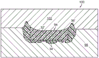
FIG. 8 is an elevation view of a third mold assembly having a top plate and a bottom plate, shown in exploded form, further showing a preform prior to being disposed in the bottom plate.
FIG. 9 is a front view of the third mold assembly of FIG. 8 showing a preform in a recess of the bottom plate.
Fig. 10 is an elevation view of the third mold assembly of fig. 8, shown in a closed state.
The drawings described above are not necessarily to scale, should be understood to provide a schematic representation of certain embodiments of the invention, and are merely conceptual views and illustrative of the principles involved. Some features of the mold assembly used to fabricate the sole assembly have been enlarged or distorted relative to others to facilitate explanation and understanding. In the drawings, the same reference numerals have been used for similar or identical components and features shown in various alternative embodiments. The mold assemblies for sole assemblies and methods of making such sole assemblies disclosed herein will have configurations and components determined, in part, by the intended application and environment in which they are used.
Detailed Description
Article of footwear 10 is depicted in fig. 1 as including an upper 12 and a sole assembly 14. For ease of reference in the following description, footwear 10 may be divided into three general regions: a forefoot region 16, a midfoot region 18, and a heel region 20. Regions 16 through 20 are not intended to demarcate precise areas of footwear 10. Rather, regions 16-20 are intended to represent general areas of footwear 10 that are referenced during the following discussion. Although regions 16-20 apply generally to footwear 10, references to regions 16-20 may also apply specifically to upper 12, sole assembly 14, or individual components within either upper 12 or sole assembly 14.
For example, sole assembly 14 may be secured directly to upper 12 with an adhesive. Suitable binders are well known in the art and need not be discussed in more detail herein. Any other suitable fastening means may be utilized to secure sole assembly 14 to upper 12, and other suitable means of securing sole assembly 14 to upper 12 will be readily apparent to those skilled in the art upon reading this disclosure.
It should be appreciated that in some embodiments, sole assembly 14 may function as a midsole, with an outsole (not shown) secured to a bottom surface of the midsole. In other embodiments, as shown herein, the bottom surface of sole assembly 14 serves as the ground-engaging portion (or other contact surface-engaging portion) of footwear 10.
As shown in the embodiment of FIG. 2, sole assembly 14 includes a first core portion 32, one or more inserts 34, and a perimeter portion 36. The core portion 32 is formed of a first color, the insert 34 is formed of a second color, and the perimeter portion 36 is formed of a third color. Although three colors are used in the present embodiment, it should be appreciated that any number of different colors may be applied to the various components of sole assembly 14, depending on the manufacturing method described below.
In certain embodiments, the core portion 32, the insert 34, and the perimeter portion 36 may beFormed of injected phylon (ethylene vinyl acetate or "EVA"). The EVA may have a Vinyl Acetate (VA) content between about 9% and about 40%. For example, suitable EVA resins include those supplied by DuPont corporation (DuPont) And Engage supplied by Dow Chemical Company (Dow Chemical Company). In certain embodiments, the EVA may be formed from a combination of high and low melt index materials. For example, EVA may have a melt index between about 1 and about 50.
The EVA can also include various components, including blowing agents. The blowing agent may have a weight percentage between about 10% to about 20%. For example, suitable blowing agents include azodicarbonamide. In certain embodiments, peroxide-based curing agents, such as dicumyl peroxide, may be used. The amount of curing agent may be between about 0.6% to about 1.5%. EVA may also include leveling agents, processing aids, and waxes. For example, mixtures of light aliphatic hydrocarbons may be included, e.g.And 60 NS. EVA may also include other components, such as mold release agents (e.g., stearic acid), activators (e.g., zinc oxide), fillers (e.g., magnesium carbonate), pigments, and clays.
As shown in fig. 2, perimeter portion 36 may form the entire outer perimeter 38 of sole component 14. In other embodiments, the perimeter portion 36 may form only a portion of the outer perimeter 38. As shown here, the perimeter portion 36 may also completely surround the outer perimeter 40 of the core portion 32. As shown here, the insert 34 may be completely surrounded by and contained within the core portion 32.
The preforms of the components of sole assembly 14 are shown in exploded form in fig. 3. As shown here, the core portion preform 32' includes ribs 42 that extend downwardly from a lower surface 44 and define a plurality of interior depressions 46. Each insert preform 34' is configured to be positioned or received in one of the interior recesses 46. The ribs 42 also define a shoulder 48 that extends around at least a portion of the core preform 32'.
An aperture 50 extending through the perimeter portion preform 36 'defines an internal lip 52 that is positioned over the shoulder 48 of the core portion preform 32'. As shown in fig. 2, in the finished article of sole component 14, the surface of aperture 50 abuts the outer perimeter of rib 42.
As shown in fig. 3 herein, surface irregularities 53 may be formed in the lower surfaces of core portion preform 32 ', insert preform 34 ', and perimeter portion preform 36 '. Surface irregularities 53 may take any desired shape. In the illustrated embodiment, the surface irregularities 53 include a plurality of grooves 55 and lugs or projections 57 that form a grid of hexagonal projections 57 with corresponding grooves 55 surrounding the projections, as shown more clearly in the sole component 14 of fig. 2. The surface irregularities 53 may have the effect of providing aesthetics as well as performance.
A method of forming sole assembly 14 that reduces color bleed between the colors of core portion preform 32 ', insert preform 34 ', and perimeter portion preform 36 ' will now be described. As shown in fig. 4, the first preform mold assembly 54 for forming the core preform 32' includes an upper plate 56 and a lower plate 58. The upper plate 56 and the lower plate 58 may be rotatably secured to each other by a hinge 60. A projection 61 extending downwardly from the upper plate 56 and a lower recess 62 formed in the lower plate 58 cooperate to define a core recess 63. As shown here, the first preform mold assembly 54 includes two core recesses 63 to simultaneously form the core portion preforms 32' for both the left and right sole assemblies.
The recess 64 formed in the bottom of the core recess 63 is used to form the rib 42 when the core section preform 32' is formed in the first preform mold assembly 54. The recesses 64 may include surface irregularities 66 for forming mating surface irregularities 53 in the lower surface of the ribs 42, as described above in connection with fig. 2.
The core portion preform 32' is formed in a known manner in the core recess 63 of the first preform mold assembly 54 while heated EVA is inserted into the core recess 63. The resulting EVA core preform piece 32 ' is later combined with insert preform piece 34 ' and perimeter preform piece 36 ' to form sole assembly 14, as described in more detail below.
A second preform mold assembly 68, shown in fig. 5, is used to form the insert preform 34 'and the perimeter portion preform 36'. The second preforming tool assembly 68 includes a bottom plate 70, a top plate 72, a core plate 73 disposed below the top plate 72, and sidewall plates 74 disposed between the bottom plate 70 and the core plate 73. The plates of the second pre-form die assembly 68 are connected by hinges 76. The projections 78 extending downwardly from the core plate 73, the apertures 80 extending through the side wall plates 74, and the recesses 82 formed in the top surface of the bottom plate 70 cooperate to define a first or insert recess 84 and a second or perimeter recess 86, as shown in fig. 6 and 7. As shown here, the second preform mold assembly 68 includes two sets of insert recesses 84 and two perimeter recesses 63 to simultaneously form insert preforms 34 'and perimeter portion preforms 36' for both the left and right sole assemblies.
For illustrative purposes, the perimeter portion preform 36 ' with the insert preform 34 ' positioned in the perimeter portion preform 36 ' and formed in the second preform mold assembly 68 is shown here in the right side recess 82 of the bottom plate 70. It should be understood that any number of insert preforms 34' may be formed in the second preform mold assembly 68. In the illustrated embodiment, there are three insert preforms 34' used to form sole assembly 14. It should be appreciated that a single insert preform 34 'or any number of insert preforms 34' may be used to form sole assembly 14.
As shown in fig. 6, the side wall panels 74 and core panel 73 are pivoted downwardly onto the base panel 70 into a closed position. The heated EVA used to form the perimeter portion preform 36' is then injected through a first gate 90 formed in the core plate 73, as indicated by arrow a. The EVA for the perimeter portion preform 36' is thus disposed within the perimeter recess 63.
After heated EVA is injected into the perimeter recess 63, the top plate 72 is then pivoted down onto the core plate 73 into the closed position. The heated EVA used to form the insert portion 34' is then injected into the insert recess 84 through the second gate 92 formed in the top plate 72 and core plate 73. Thus, the configuration of second preform mold assembly 68 allows for the simultaneous formation of two different colors of injected EVA material, thereby forming both insert preform 34 'and perimeter portion preform 36'.
All preforms (i.e., core portion preform 32 ', insert preform 34 ', and perimeter portion preform 36 ') each having a different color are then preassembled into a single sole assembly preform 94. As shown in fig. 8-10, this integral sole assembly preform 94 formed of all three colors of material is then placed in a single step into a recess 96 formed in a heated base plate 98 of a third mold assembly 100, as indicated by arrow C. Once sole component preform 94 is positioned in recess 96, top plate 102 of third mold assembly 100 is placed on bottom plate 98, thereby closing third mold assembly 100. Sole assembly preform 94 is then heated within third mold assembly 100 for a predetermined duration to bond core portion preform 32 ', insert preform 34 ', and perimeter portion preform 36 ' to one another to form sole assembly 14.
In certain embodiments, third mold assembly 100 is held at a temperature between about 170 ℃ and 180 ℃ for about 10 minutes. The particular temperature and duration for forming sole component 14 in third mold assembly 100 may vary in a known manner, depending on the particular EVA used.
In a known manner, sole assembly 14 will expand after sole assembly 14 is removed from third mold assembly 100. Sole assembly 14 is then subjected to typical stabilization steps, including cooling and trimming, as desired.
By inserting the entire unitary preform 94 into recess 96 simultaneously, all material begins to melt simultaneously after being inserted into third mold assembly 100, so bleeding between the differently colored portions of preform 94 when forming sole assembly 14 is reduced.
In certain embodiments, as shown in FIG. 2 and described above, the surface irregularities 53 may form a defined pattern. As shown in the embodiments illustrated herein, the surface irregularities 53 form a grid of hexagonal protrusions 57 by means of corresponding grooves 55 formed around the protrusions 57. In this embodiment, it may be advantageous to have boundaries between the different colors, i.e., the color boundaries between the core portion 32, the insert 34, and the perimeter portion 36 do not exactly match or coincide along the edges of the projections 57 or the grooves 55. Any bleeding between different colors will be more easily detected if one tries to align the color boundary with the edge of the protrusion 57 or the groove 55. If the color boundary lines span the protrusion 57, rather than just along the perimeter of the protrusion 57, the user's eyes will be less likely to notice color bleed.
Thus, while there have been shown, described, and pointed out fundamental novel features of various embodiments, it will be understood that various omissions, substitutions, and changes in the form and details of the devices illustrated, and in their operation, may be made by those skilled in the art without departing from the spirit and scope of the invention. For example, it is expressly intended that all combinations of those elements and/or steps which perform substantially the same function in substantially the same way to achieve the same results are within the scope of the invention. The invention also fully contemplates and contemplates the replacement of elements from one described embodiment to another. It is the intention, therefore, to be limited only as indicated by the scope of the claims appended hereto.
Claims (10)
1. A sole assembly, comprising:
a core portion including a lower surface and a rib extending downwardly from the lower surface, wherein the rib defines a shoulder extending around at least a portion of the core portion;
a first insert contained within and bonded to the core portion; and
a peripheral portion joined to the core portion, wherein the peripheral portion forms at least a portion of an outer periphery of the sole assembly, wherein the peripheral portion includes an aperture defining an interior lip, and wherein the interior lip is positioned on the shoulder of the core portion.
2. The sole assembly of claim 1, wherein an outer peripheral edge of the first insert is completely surrounded by the core portion and contained within a first interior recess defined by the ribs of the core portion.
3. The sole assembly of claim 1, wherein the perimeter portion completely surrounds an outer perimeter of the core portion.
4. The sole assembly of claim 1, wherein a surface of the aperture abuts an outer perimeter of the rib.
5. The sole assembly of claim 1, wherein a lower surface of the core portion, a lower surface of the first insert, and a lower surface of the perimeter portion include a plurality of grooves and lugs or protrusions.
6. The sole assembly of claim 1, wherein the core portion has a first color, the first insert has a second color different from the first color, and the perimeter portion has a third color different from the first color and the second color.
7. The sole assembly of claim 1, wherein each of the core portion, the first insert, and the perimeter portion is an ethylene vinyl acetate material.
8. The sole assembly of claim 1, wherein the perimeter portion forms an entire outer perimeter of the sole assembly.
9. The sole assembly of claim 1, wherein the core portion, the first insert, and the perimeter portion have different hardnesses from one another.
10. The sole assembly of claim 1, wherein the first insert is located in a forefoot region of the sole assembly.
Applications Claiming Priority (3)
| Application Number | Priority Date | Filing Date | Title |
|---|---|---|---|
| US14/252,045 US10226906B2 (en) | 2014-04-14 | 2014-04-14 | Method of manufacturing sole assembly formed of multiple preforms |
| US14/252,045 | 2014-04-14 | ||
| CN201580018491.5A CN106163312B (en) | 2014-04-14 | 2015-04-01 | The method for manufacturing the sole assembly formed by multiple preformed members |
Related Parent Applications (1)
| Application Number | Title | Priority Date | Filing Date |
|---|---|---|---|
| CN201580018491.5A Division CN106163312B (en) | 2014-04-14 | 2015-04-01 | The method for manufacturing the sole assembly formed by multiple preformed members |
Publications (1)
| Publication Number | Publication Date |
|---|---|
| CN110840008A true CN110840008A (en) | 2020-02-28 |
Family
ID=53002804
Family Applications (2)
| Application Number | Title | Priority Date | Filing Date |
|---|---|---|---|
| CN201580018491.5A Active CN106163312B (en) | 2014-04-14 | 2015-04-01 | The method for manufacturing the sole assembly formed by multiple preformed members |
| CN201911131712.6A Pending CN110840008A (en) | 2014-04-14 | 2015-04-01 | Method of manufacturing a sole assembly formed from a plurality of preforms |
Family Applications Before (1)
| Application Number | Title | Priority Date | Filing Date |
|---|---|---|---|
| CN201580018491.5A Active CN106163312B (en) | 2014-04-14 | 2015-04-01 | The method for manufacturing the sole assembly formed by multiple preformed members |
Country Status (6)
| Country | Link |
|---|---|
| US (2) | US10226906B2 (en) |
| EP (2) | EP3131744B1 (en) |
| KR (2) | KR101947253B1 (en) |
| CN (2) | CN106163312B (en) |
| MX (1) | MX2016012919A (en) |
| WO (1) | WO2015160507A1 (en) |
Families Citing this family (21)
| Publication number | Priority date | Publication date | Assignee | Title |
|---|---|---|---|---|
| AT510967B1 (en) * | 2011-09-20 | 2012-08-15 | Julia Mag Stoehr | METHOD AND DEVICE FOR PRODUCING A FOOTBED FOR A SHOE |
| US20160302519A1 (en) * | 2015-04-17 | 2016-10-20 | Adidas Ag | Article of Footwear Having a Midsole and Methods of Making the Same |
| US10251446B2 (en) | 2015-10-30 | 2019-04-09 | Reebok International Limited | Pressure mapped midsoles, articles of footwear including the same, and methods of making the same |
| US20190090585A1 (en) * | 2017-09-22 | 2019-03-28 | Wolverine Outdoors, Inc. | Sole assembly for article of footwear |
| IT201800001171A1 (en) * | 2018-01-17 | 2019-07-17 | Merelli Compositi S R L | MANUFACTURING METHOD OF A COMPONENT OF A FOOTWEAR AND SHOE FITTED WITH THIS COMPONENT |
| EP3694363B1 (en) * | 2017-10-12 | 2022-04-27 | Stilo S.r.l. | Production method of a component of a footwear and footwear provided with said component |
| US10716359B2 (en) | 2018-01-23 | 2020-07-21 | Nike, Inc. | Sole structure for article of footwear |
| EP4140348A1 (en) * | 2018-05-31 | 2023-03-01 | NIKE Innovate C.V. | Method of manufacturing an article of footwear with a thermoformed siped sole structure |
| USD894571S1 (en) * | 2018-06-01 | 2020-09-01 | Cole Haan Llc | Shoe sole |
| USD893152S1 (en) * | 2018-06-01 | 2020-08-18 | Cole Haan Llc | Shoe sole |
| EP3797632A4 (en) * | 2018-12-11 | 2022-01-12 | ASICS Corporation | Shoe |
| USD878016S1 (en) * | 2019-01-04 | 2020-03-17 | Nike, Inc. | Shoe |
| USD876056S1 (en) * | 2019-01-04 | 2020-02-25 | Nike, Inc. | Shoe |
| USD873546S1 (en) * | 2019-01-04 | 2020-01-28 | Nike, Inc. | Shoe |
| USD922048S1 (en) * | 2019-01-17 | 2021-06-15 | Vibram S.P.A. | Sole for footwear |
| CN210611192U (en) * | 2019-04-03 | 2020-05-26 | 霍尼韦尔国际公司 | Footwear outsole with resistance elements |
| USD913669S1 (en) * | 2019-09-03 | 2021-03-23 | Nike, Inc. | Shoe |
| CN116076832B (en) | 2020-01-10 | 2024-03-12 | 耐克创新有限合伙公司 | Sole structure with multiple stiffness and/or bend-enhancing structures |
| USD977234S1 (en) * | 2020-06-03 | 2023-02-07 | Tbl Licensing Llc | Footwear |
| USD919947S1 (en) * | 2020-06-18 | 2021-05-25 | Tingting Shi | Shoe sole |
| CN112238635A (en) * | 2020-09-16 | 2021-01-19 | 东莞市隆华鞋业有限公司 | Preparation method of wrapping type sole integrally formed by injecting EVA and CPU |
Citations (13)
| Publication number | Priority date | Publication date | Assignee | Title |
|---|---|---|---|---|
| CN1141610A (en) * | 1994-11-10 | 1997-01-29 | R·O·奥利沃希尔瓦 | Process for mfg. articles in expanded reticular polymeric materials and the resulting products |
| DE19812694A1 (en) * | 1997-08-29 | 1999-03-04 | Young Chang New Technology Cor | Molding an injection foamed product with material sections having different properties |
| US20050126038A1 (en) * | 2003-12-12 | 2005-06-16 | K-Swiss Inc. | Method for forming footwear structures using thermoforming |
| CN101472493A (en) * | 2006-06-20 | 2009-07-01 | 健乐士股份公司 | Moisture permeable element for composing shoe soles, soles with the moisture permeable element and shoe with the soles |
| CN102144827A (en) * | 2010-02-05 | 2011-08-10 | 德克斯户外公司 | Footwear including a self-adjusting midsole |
| CN102481746A (en) * | 2009-09-02 | 2012-05-30 | 耐克国际有限公司 | Method of manufacturing sole assembly for article of footwear |
| WO2013023135A1 (en) * | 2011-08-10 | 2013-02-14 | Nike International Ltd. | Article of footwear formed from two preforms and method and mold for manufacturing same |
| CN202873956U (en) * | 2012-08-24 | 2013-04-17 | 福建省晋江市帝星鞋塑有限公司 | Antiskid and anti-shock sport shoe |
| CN203058521U (en) * | 2012-12-26 | 2013-07-17 | 福建泉州匹克体育用品有限公司 | Sole with gradient dual-energy technology |
| KR20130093982A (en) * | 2012-02-15 | 2013-08-23 | 주식회사 트렉스타 | Sole of shoe and manufacturing method thereof |
| CN103298362A (en) * | 2010-09-03 | 2013-09-11 | W.L.戈尔有限公司 | Shoe, sole assembly for a shoe, method for manufacturing a sole assembly and method for manufacturing a shoe |
| US20140015169A1 (en) * | 2012-07-11 | 2014-01-16 | Nike, Inc. | Mold for Footwear with Sipes and Method of Manufacturing Same |
| US20140075779A1 (en) * | 2012-09-20 | 2014-03-20 | Nike, Inc. | Sole Structures and Articles of Footwear Having Plate Moderated Fluid-Filled Bladders and/or Foam Type Impact Force Attenuation Members |
Family Cites Families (15)
| Publication number | Priority date | Publication date | Assignee | Title |
|---|---|---|---|---|
| US4700652A (en) * | 1986-06-09 | 1987-10-20 | Pekny Robert E | Marine anchor |
| US4760652A (en) | 1987-06-04 | 1988-08-02 | Quabaug Corporation | Composite outsole |
| FR2733880B3 (en) * | 1995-05-11 | 1997-04-18 | Chi Kuan Jen | SHOE SOLE COMPRISING A DRAWING |
| CA2179873C (en) * | 1995-07-14 | 2002-08-27 | Norman H. Finn | Shoe sole having co-molded anti-skid insert |
| US6061929A (en) * | 1998-09-04 | 2000-05-16 | Deckers Outdoor Corporation | Footwear sole with integrally molded shank |
| US7065820B2 (en) * | 2003-06-30 | 2006-06-27 | Nike, Inc. | Article and method for laser-etching stratified materials |
| US7451557B2 (en) | 2004-06-04 | 2008-11-18 | Nike, Inc. | Article of footwear with a removable midsole element |
| ITMI20041183A1 (en) * | 2004-06-11 | 2004-09-11 | Vibram Spa | PROCEDURE FOR THE CREATION OF PERFORATED E-OR TWO-COLOR COMPONENTS, PARTICULARLY FOR FOOTWEAR IN GENERAL |
| WO2008019980A2 (en) | 2006-08-14 | 2008-02-21 | Main Group Corporation S.R.L. | Method for molding multicolor ethyl vinyl acetate articles and apparatus for performing the method |
| US20080073806A1 (en) | 2006-09-27 | 2008-03-27 | Wang Ming-Hui | Method for foaming multiple color sole |
| US20100098797A1 (en) | 2008-10-16 | 2010-04-22 | Davis Carrie L | Mold assembly for midsole and method of manufaturing same |
| US9931804B2 (en) * | 2008-11-14 | 2018-04-03 | Nike, Inc. | Decorated sole elements for articles of footwear and processes for making thereof |
| WO2011082275A1 (en) * | 2009-12-30 | 2011-07-07 | Li Ning Sports Usa, Inc. | Lastless, molded footwear and methods of construction |
| US10010136B2 (en) * | 2011-03-16 | 2018-07-03 | Nike, Inc. | Footwear sole structure incorporating a plurality of chambers |
| DE102013208170B4 (en) * | 2013-05-03 | 2019-10-24 | Adidas Ag | Sole for a shoe and shoe with such a sole |
-
2014
- 2014-04-14 US US14/252,045 patent/US10226906B2/en active Active
-
2015
- 2015-04-01 MX MX2016012919A patent/MX2016012919A/en unknown
- 2015-04-01 WO PCT/US2015/023792 patent/WO2015160507A1/en active Application Filing
- 2015-04-01 KR KR1020167027949A patent/KR101947253B1/en active IP Right Grant
- 2015-04-01 EP EP15718397.1A patent/EP3131744B1/en active Active
- 2015-04-01 CN CN201580018491.5A patent/CN106163312B/en active Active
- 2015-04-01 EP EP18213385.0A patent/EP3476235B1/en active Active
- 2015-04-01 CN CN201911131712.6A patent/CN110840008A/en active Pending
- 2015-04-01 KR KR1020197001971A patent/KR102113243B1/en active IP Right Grant
-
2019
- 2019-01-29 US US16/260,774 patent/US20190168475A1/en not_active Abandoned
Patent Citations (13)
| Publication number | Priority date | Publication date | Assignee | Title |
|---|---|---|---|---|
| CN1141610A (en) * | 1994-11-10 | 1997-01-29 | R·O·奥利沃希尔瓦 | Process for mfg. articles in expanded reticular polymeric materials and the resulting products |
| DE19812694A1 (en) * | 1997-08-29 | 1999-03-04 | Young Chang New Technology Cor | Molding an injection foamed product with material sections having different properties |
| US20050126038A1 (en) * | 2003-12-12 | 2005-06-16 | K-Swiss Inc. | Method for forming footwear structures using thermoforming |
| CN101472493A (en) * | 2006-06-20 | 2009-07-01 | 健乐士股份公司 | Moisture permeable element for composing shoe soles, soles with the moisture permeable element and shoe with the soles |
| CN102481746A (en) * | 2009-09-02 | 2012-05-30 | 耐克国际有限公司 | Method of manufacturing sole assembly for article of footwear |
| CN102144827A (en) * | 2010-02-05 | 2011-08-10 | 德克斯户外公司 | Footwear including a self-adjusting midsole |
| CN103298362A (en) * | 2010-09-03 | 2013-09-11 | W.L.戈尔有限公司 | Shoe, sole assembly for a shoe, method for manufacturing a sole assembly and method for manufacturing a shoe |
| WO2013023135A1 (en) * | 2011-08-10 | 2013-02-14 | Nike International Ltd. | Article of footwear formed from two preforms and method and mold for manufacturing same |
| KR20130093982A (en) * | 2012-02-15 | 2013-08-23 | 주식회사 트렉스타 | Sole of shoe and manufacturing method thereof |
| US20140015169A1 (en) * | 2012-07-11 | 2014-01-16 | Nike, Inc. | Mold for Footwear with Sipes and Method of Manufacturing Same |
| CN202873956U (en) * | 2012-08-24 | 2013-04-17 | 福建省晋江市帝星鞋塑有限公司 | Antiskid and anti-shock sport shoe |
| US20140075779A1 (en) * | 2012-09-20 | 2014-03-20 | Nike, Inc. | Sole Structures and Articles of Footwear Having Plate Moderated Fluid-Filled Bladders and/or Foam Type Impact Force Attenuation Members |
| CN203058521U (en) * | 2012-12-26 | 2013-07-17 | 福建泉州匹克体育用品有限公司 | Sole with gradient dual-energy technology |
Non-Patent Citations (2)
| Title |
|---|
| 林少勋: "《运动鞋设计》", 31 January 2007 * |
| 金绍文: "《制鞋机械》", 30 June 2012 * |
Also Published As
| Publication number | Publication date |
|---|---|
| EP3476235B1 (en) | 2022-03-09 |
| US20150290892A1 (en) | 2015-10-15 |
| EP3131744B1 (en) | 2019-01-09 |
| CN106163312B (en) | 2019-12-03 |
| KR102113243B1 (en) | 2020-05-21 |
| EP3131744A1 (en) | 2017-02-22 |
| KR20190009845A (en) | 2019-01-29 |
| EP3476235A1 (en) | 2019-05-01 |
| US20190168475A1 (en) | 2019-06-06 |
| KR101947253B1 (en) | 2019-02-12 |
| CN106163312A (en) | 2016-11-23 |
| US10226906B2 (en) | 2019-03-12 |
| WO2015160507A1 (en) | 2015-10-22 |
| MX2016012919A (en) | 2017-01-09 |
| KR20160132921A (en) | 2016-11-21 |
Similar Documents
| Publication | Publication Date | Title |
|---|---|---|
| US20190168475A1 (en) | Sole Assembly Formed of Multiple Preforms | |
| US10869523B2 (en) | Sole assembly formed from multiple preforms and method and mold for manufacturing same | |
| US20200315290A1 (en) | Soles for sports shoes | |
| EP3057784B1 (en) | Method of manufacturing rubber and polyolefin sole assembly | |
| US10245798B2 (en) | Method for manufacturing a midsole formed from two preforms | |
| KR20120000098A (en) | Method of manufacturing footwear having sipes in the sole | |
| EP2961594B1 (en) | Method of forming midsole of two materials | |
| EP3267817B1 (en) | Method of manufacturing sole assembly with camouflage appearance |
Legal Events
| Date | Code | Title | Description |
|---|---|---|---|
| PB01 | Publication | ||
| PB01 | Publication | ||
| SE01 | Entry into force of request for substantive examination | ||
| SE01 | Entry into force of request for substantive examination |