CN110832711B - RF PCB connector with surface mount interface - Google Patents
RF PCB connector with surface mount interface Download PDFInfo
- Publication number
- CN110832711B CN110832711B CN201880044648.5A CN201880044648A CN110832711B CN 110832711 B CN110832711 B CN 110832711B CN 201880044648 A CN201880044648 A CN 201880044648A CN 110832711 B CN110832711 B CN 110832711B
- Authority
- CN
- China
- Prior art keywords
- pcb
- connector
- surface mount
- housing
- interface
- Prior art date
- Legal status (The legal status is an assumption and is not a legal conclusion. Google has not performed a legal analysis and makes no representation as to the accuracy of the status listed.)
- Active
Links
Images


Classifications
-
- H—ELECTRICITY
- H01—ELECTRIC ELEMENTS
- H01R—ELECTRICALLY-CONDUCTIVE CONNECTIONS; STRUCTURAL ASSOCIATIONS OF A PLURALITY OF MUTUALLY-INSULATED ELECTRICAL CONNECTING ELEMENTS; COUPLING DEVICES; CURRENT COLLECTORS
- H01R24/00—Two-part coupling devices, or either of their cooperating parts, characterised by their overall structure
- H01R24/38—Two-part coupling devices, or either of their cooperating parts, characterised by their overall structure having concentrically or coaxially arranged contacts
- H01R24/40—Two-part coupling devices, or either of their cooperating parts, characterised by their overall structure having concentrically or coaxially arranged contacts specially adapted for high frequency
- H01R24/42—Two-part coupling devices, or either of their cooperating parts, characterised by their overall structure having concentrically or coaxially arranged contacts specially adapted for high frequency comprising impedance matching means or electrical components, e.g. filters or switches
- H01R24/44—Two-part coupling devices, or either of their cooperating parts, characterised by their overall structure having concentrically or coaxially arranged contacts specially adapted for high frequency comprising impedance matching means or electrical components, e.g. filters or switches comprising impedance matching means
-
- H—ELECTRICITY
- H01—ELECTRIC ELEMENTS
- H01R—ELECTRICALLY-CONDUCTIVE CONNECTIONS; STRUCTURAL ASSOCIATIONS OF A PLURALITY OF MUTUALLY-INSULATED ELECTRICAL CONNECTING ELEMENTS; COUPLING DEVICES; CURRENT COLLECTORS
- H01R24/00—Two-part coupling devices, or either of their cooperating parts, characterised by their overall structure
- H01R24/38—Two-part coupling devices, or either of their cooperating parts, characterised by their overall structure having concentrically or coaxially arranged contacts
- H01R24/40—Two-part coupling devices, or either of their cooperating parts, characterised by their overall structure having concentrically or coaxially arranged contacts specially adapted for high frequency
- H01R24/50—Two-part coupling devices, or either of their cooperating parts, characterised by their overall structure having concentrically or coaxially arranged contacts specially adapted for high frequency mounted on a PCB [Printed Circuit Board]
-
- H—ELECTRICITY
- H05—ELECTRIC TECHNIQUES NOT OTHERWISE PROVIDED FOR
- H05K—PRINTED CIRCUITS; CASINGS OR CONSTRUCTIONAL DETAILS OF ELECTRIC APPARATUS; MANUFACTURE OF ASSEMBLAGES OF ELECTRICAL COMPONENTS
- H05K1/00—Printed circuits
- H05K1/02—Details
- H05K1/0213—Electrical arrangements not otherwise provided for
- H05K1/0237—High frequency adaptations
- H05K1/0243—Printed circuits associated with mounted high frequency components
-
- H—ELECTRICITY
- H01—ELECTRIC ELEMENTS
- H01R—ELECTRICALLY-CONDUCTIVE CONNECTIONS; STRUCTURAL ASSOCIATIONS OF A PLURALITY OF MUTUALLY-INSULATED ELECTRICAL CONNECTING ELEMENTS; COUPLING DEVICES; CURRENT COLLECTORS
- H01R2103/00—Two poles
Abstract
The RF connector system includes an RF connector having a PCB interface and a Printed Circuit Board (PCB), the RF connector further including a housing, a coaxial RF connector interface, and a PCB contact section. The mechanical connection is formed by two wing-shaped surface mount sections of the housing having a plurality of surface mount posts adapted to mate with a plurality of pads on the PCB. An electrical connection to the PCB is formed by the inner conductor and at least one matching block electrically connected to the housing and providing a matched impedance at the PCB, the PCB having a stripline and a ground plane.
Description
Technical Field
The present invention relates to an RF PCB connector assembly that can be used for millimeter wave and has a surface mount interface for a Printed Circuit Board (PCB).
Background
An RF connector assembly is disclosed in US 6,607,400B 1. The connector is mounted in a cutout of the printed circuit board. Electrical contact is established by soldering the pads to the ground plane and the signal lines. Due to its design, such a connector is only suitable for frequencies of the order of up to 1 GHz. The connector is a micro-button connector. Larger connectors, which are heavier, cannot be mounted through the disclosed PCB interface.
A millimeter wave connector for interconnecting microstrip circuitry and external circuitry is disclosed in US 4,669,805. The connector is held in a housing that also includes a microstrip substrate to be connected to the connector. During assembly, the flexible center conductor of the connector must bend to accommodate the microstrip circuit. The bending of the center conductor may cause asymmetry, thereby degrading the electrical characteristics of the connector.
Disclosure of Invention
The problem to be solved by the present invention is to provide a millimeter wave connector that can be mounted to a Printed Circuit Board (PCB) or any other microstrip substrate without the need for complex and expensive mounting tools. The connector should be designed so that it can be installed by automated tools.
A solution to this problem is described in the independent claims. The dependent claims relate to further developments of the invention.
A millimeter wave or RF connector for a printed circuit board includes a housing, an RF connector interface, and a printed circuit board interface. The RF PCB connector defines a mounting plane. The mounting plane is a common plane for all surface mount components of the connector. The mounting plane is also the plane of the PCB to which the connector can be mounted.
The RF connector interface may be any standard RF connector interface, such as SMA, 2.92mm, 1.85mm, or 1.0 mm. The RF connector interface preferably provides a coaxial connector interface having an outer conductor and an inner conductor. The coaxial RF connector interface may be mounted or attached to the housing. Preferably, the outer conductor is part of the housing such that it is integral with the housing.
The case may include a metal block having a rectangular parallelepiped shape. The housing comprises at least one, preferably two, surface mount sections which may be part of the housing and are preferably integral with the housing. The surface mount sections may be formed as side wings of the housing, thus requiring less space and material. Furthermore, the flanks provide a lower heat capacity. The at least one surface mount section has a plurality of surface mount studs, preferably integral with the surface mount section and having a flat end surface lying in a mounting plane. The surface mount stud may be soldered to the surface of the printed circuit board using the end surface of the surface mount stud. The surface mount studs may be soldered to a continuous metal surface, such as a ground plane. It is preferable to solder the surface mount posts to the mating contact pads. These contact pads may be insulated from each other and/or from the system ground (system ground) since the ground connection may be made through a matching block which is part of the PCB contact section and which is arranged close to the inner conductor outlet of the housing. The contact pads may also be used to further ground the connector. Most preferably, when using contact pads that mate with surface mount studs, the centering of each surface mount stud with respect to the corresponding contact pad is done automatically by the surface tension of the solder metal. Such solder metal may be any metal or combination of metals known from the prior art, such as tin, lead, silver, and the like. The centering of the various surface mount posts results in overall alignment of the RF connectors. Furthermore, the RF connector can be easily handled by an automated pick and place system and no additional processing steps are required.
The housing preferably comprises an electrically conductive material, most preferably a metal.
Since the outer conductor of the RF connector is connected to the housing or a part of the housing, the outer connector can be contacted with the printed circuit board by means of surface mounted studs.
The center conductor (also referred to as the inner conductor) of the coaxial RF connector interface is guided through the housing, preferably within the coaxial bore, to maintain the coaxial structure by minimizing reflections. The inner conductor leaves the housing at the PCB contact section, preferably at a side opposite to the side of the coaxial RF connector interface, and has a contact area lying in the mounting plane. At least one matching block is provided on the outlet side of the housing, close to the inner conductor, which makes electrical contact with the housing, which maintains the capacitance of the inner conductor in the region of the outlet side and the contact of the inner conductor with the strip line of the printed circuit board, which corresponds to the inductance, so that the characteristic impedance is always constant and reflections are minimized. Preferably, there are two matching blocks arranged symmetrically. Most preferably, the mating blocks have contact surfaces that lie in the mounting plane so that they can contact the ground plane of the printed circuit board. Preferably, the mating block also serves as a pad for soldering to provide electrical connection to the ground plane of the printed circuit board.
To position the housing, a cutout may be provided in the printed circuit board. Preferably, the cut-out is at least slightly larger than the housing, such that there is a gap between the cut-out and the housing. It is not necessary to precisely match the cut-outs with the housing and to hold the housing, since the housing itself is precisely centered by the surface mount studs, which are further centered with respect to the contact pads. Such a precise alignment is necessary to provide a perfect alignment of the inner conductor with the stripline at the exit side, which further results in minimal reflection at high frequencies.
In a preferred embodiment, there is provided an RF connector system comprising at least one RF connector as described above and a mating printed circuit board also as described above. In order to self-align the RF connector with the printed circuit board, the contact pads of the printed circuit board preferably mate with the surface mount posts of the RF connector. Preferably, the contact pads and surface mount studs have a rectangular cross-section, most preferably a square cross-section. It is further preferred that the size of the contact pads be 0.05mm to 0.15mm larger than the size of the surface mount posts. The surface mount stud may also have a circular or oval shape, while the contact pad, which may have a rectangular, circular or oval shape, is preferably 0.05mm to 0.15mm larger in size than the stud.
Preferably, the housing, and most preferably, the surface mount studs and mating blocks have surfaces that can be easily welded. Preferably, the surface is plated.
Drawings
The invention will be described hereinafter by way of example of embodiments with reference to the accompanying drawings without limiting the general inventive concept.
Fig. 1 shows a perspective view of an RF connector with a PCB interface.
Fig. 2 shows a detailed view of the surface mount section.
Fig. 3 shows details of the connection manner of the inner conductor.
Figure 4 shows a detail of a surface mount stud.
Fig. 5 shows a top view of an RF connector with a PCB interface.
Fig. 6 shows a cross-sectional view of an RF connector with a PCB interface.
Fig. 7 shows a side view.
Fig. 8 shows a bottom view.
Fig. 9 shows an enlarged cross-sectional view of fig. 7.
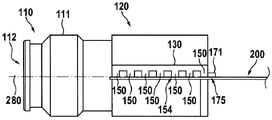
In fig. 1, a perspective view of an RF connector 100 with a PCB interface is shown. The RF connector includes a housing 120, the housing 120 including a coaxial RF connector interface 110, preferably the housing 120 retains or is integral with the coaxial RF connector interface 110.
The coaxial RF connector interface 110 has an outer conductor 111 and a center conductor 112 coaxial with the outer conductor 111. The center conductor 112 is not visible here, but will be shown in detail later. The coaxial RF connector interface may be of any type. The coaxial RF connector interface may be male, female or hermaphroditic.
The housing 120, which preferably comprises metal and preferably has the shape of a cuboid, further has at least one surface mounting section 130, 140, the surface mounting sections 130, 140 preferably being symmetrically arranged at two opposite sides of the housing. It is further preferred that the surface mount section has the shape of a flank. The thickness of the surface mount section may be less than the thickness of the housing, thus requiring less material and providing a lower heat capacity, which may be advantageous for soldering. The at least one surface mount section includes a plurality of surface mount posts 150. The surface mount studs are arranged in a common mounting plane so that the printed circuit board can be attached to the surface mount studs. The surface mount studs preferably have a rectangular or square cross-section, but they may have any other shape, for example a circular or elliptical cross-section.
The housing 120 preferably has a first side 121 with a coaxial RF connector interface and an outlet side 122, the outlet side 122 carrying the PCB contact section 180, the outlet side 122 preferably being opposite the first side 121. The exit side is used to bring an inner conductor, which is connected to the center conductor 112 or is part of the center conductor 112, into contact with a printed circuit board, as will be explained in more detail below.
Further, the figure shows a printed circuit board 200 having a plurality of contact pads 230 aligned with the surface mount studs. Furthermore, the printed circuit board has a strip line 220 and at least one (here: two) ground plane section 210 insulated from the strip line. These ground plane sections are electrically connected together by a plurality of through holes 211 leading to a lower electrical layer in the printed circuit board, which lower electrical layer cannot be shown here. This layer connects the ground plane sections below (or above) the striplines.
In fig. 2, a detailed view of a surface mount section 130 (section II of fig. 1) having a plurality of surface mount studs 150 is shown, the surface mount studs 150 being soldered to mating contact pads 230 of a printed circuit board 200.
In fig. 3, details of the connection manner of the inner conductor 160 (section III of fig. 1) are shown. The inner conductor 160 exits the outlet side 122 of the housing through the aperture 165 and may be soldered to the ribbon wire 220. In order to keep the end section of the inner conductor 160 with minimal reflection, preferably one matching block and most preferably two matching blocks 171, 172 are provided. These matching blocks are also preferably used to bring the housing 120 into contact with the ground plane 210 by being soldered to the ground plane 210 of the printed circuit board.
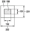
In fig. 4, details of the surface mount stud 150 are shown soldered to the mating contact pad 230. Here, the stud and the pad have a rectangular cross section, preferably a square cross section. The surface mount stud 150 has a first side length 151 and a second side length 152. The contact pad 230 has a first side length 231 and a second side length 232. It is preferable that the first side length 151 of the surface mount stud be 0.05mm to 0.15mm less than the first side length 231 of the contact pad 230. It is preferred that the second side length 152 of the surface mount stud be 0.05mm to 0.15mm less than the second side length 232 of the contact pad 230.
In fig. 5, a top view of the RF connector 100 with the PCB interface mounted to a printed circuit board is shown. Fig. 5 shows the contact pads 230 as well as the ground plane 210 and the strip line 220. To position the housing, a cutout 250 may be provided in the printed circuit board.
Preferably, the cut-out is at least slightly larger than the housing, such that there is a gap between the cut-out and the housing. It is not necessary that the cutout exactly match the housing and hold the housing because the housing itself is exactly centered by the surface mount stud, which is further centered with respect to the contact pad. Such a precise alignment is necessary to provide a perfect alignment of the inner conductor with the stripline at the exit side, which further results in minimal reflection at high frequencies.
In fig. 6, a cross-sectional view of an RF connector with a PCB interface is shown. In this view, the path of the center conductor connection is shown. The center conductor 112 of the coaxial RF connector interface is routed through a hole 165 at the outlet side 122 as an inner conductor 160. The inner conductor 160 may be integral with the center conductor 112. The inner conductor 160 may also be a wire or other metallic structure that is electrically connected and preferably mechanically connected to the center conductor 112. The center conductor 112 and/or the inner conductor 160 may be mechanically supported by a spacer 123, the spacer 123 being retained by the outer conductor section 125. In this figure, the coaxial RF connector interface 110 is held by a threaded portion 124 in the housing 120. Thus, the coaxial RF connector interface 110 may be replaceable or may be part of a modular system that includes multiple different connector interfaces that fit into the same housing.
In fig. 7, a side view of the RF connector is shown. The side view shows the mounting plane 280, and in this view the mounting plane 280 is a plane that defines the bottom of the surface mount studs and other contact components and the top side of the printed circuit board 200. The figure also indicates a flat surface 154 at the end of the surface mount stud 150. The flat surface 154 lies in the mounting plane. Also shown is the mating block contact surface 175 of the mating block 171. The surface also lies in the mounting plane.
In fig. 8, a bottom view of the connector is shown. Here, a flat surface 154 is shown. Also shown is the mating block contact surface 175. Furthermore, a contact area 162 of the inner conductor is shown.
Fig. 9 shows an enlarged cross-sectional view of fig. 7.
List of reference numerals
100 RF connector with PCB interface
110 coaxial RF connector interface
111 outer conductor
112 center conductor
120 shell
121 coaxial RF connector interface (first) side of housing
122 outlet side of the housing
123 spacer
124 thread part
125 outer conductor section
130. 140 surface mount segment
150 surface mounting column
151 length of first side
152 second side length
154 flat end surface
160 inner conductor
162 contact region
165 holes
171. 172 matching block
175 mating block contact surface
180 PCB contact section
200 Printed Circuit Board (PCB)
210 ground plane
211 through hole
220 strip line
230 contact pad
231 first side length
232 second side length
250 incision
280 mounting plane
Claims (9)
1. An RF PCB connector (100) with a PCB interface comprising a housing (120), a coaxial RF connector interface (110) and a PCB contact section (180), the RF PCB connector defining a mounting plane (280), wherein the RF PCB connector is a surface mount connector;
the coaxial RF connector interface (110) comprises an outer conductor (111) and a central conductor (112);
the housing (120) comprising at least one surface mount section (130, 140), the at least one surface mount section (130, 140) further comprising a plurality of surface mount studs (150), each of the surface mount studs (150) having a flat end surface lying in the mounting plane (280); and is
The PCB contact section (180) comprises an inner conductor (160), the inner conductor (160) passing through a hole (165) of the housing and having a contact area located in the mounting plane (280); and
at least one matching block (171, 172) having a contact surface in the mounting plane (280) and being electrically connected to the housing (120) and providing a matched impedance at the PCB contact section, the inner conductor (160) being electrically connected with the central conductor (112),
the outer conductor (111) is connected to the housing,
wherein centering of each surface mount stud with respect to a corresponding contact pad is accomplished automatically by surface tension of the solder metal when using a contact pad that mates with the surface mount stud.
2. The RF PCB connector (100) with PCB interface of claim 1, wherein the housing (120) comprises a metal block having a rectangular parallelepiped shape.
3. The RF PCB connector (100) with PCB interface of any of the preceding claims, wherein the housing (120) comprises two surface mount sections (130, 140), the two surface mount sections (130, 140) being symmetrically arranged at two opposite sides of the housing.
4. The RF PCB connector (100) with PCB interface of claim 1 or 2, wherein a thickness of the surface mount section (130, 140) is less than a thickness of the housing (120).
5. The RF PCB connector (100) with PCB interface of claim 1 or 2, wherein the surface mount stud (150) has a rectangular or square cross-section.
6. The RF PCB connector (100) with PCB interface of claim 1 or 2, wherein the PCB contact section (180) is located at an outlet side (122) of the housing (120), the outlet side (122) being opposite to a first side (121) with the coaxial RF connector interface (110).
7. An RF connector system, characterized in that the RF connector system comprises an RF PCB connector with PCB interface according to any of the preceding claims and a printed circuit board (200) comprising at least one contact pad (230) mating with the at least one surface mount post (150), at least one stripline (220) mating with the at least one inner conductor (160), and at least one ground plane (210) mating with the at least one mating block (171, 172), wherein the centering of each surface mount post with respect to the corresponding contact pad is done automatically by the surface tension of the solder metal.
8. The RF connector system of claim 7, wherein the at least one stripline (220) is insulated from the at least one ground plane (210) and is in a PCB layer above or below the at least one ground plane (210).
9. The RF connector system of claim 7 or 8, characterized in that the at least one contact pad (230) is electrically insulated from the at least one ground plane (210).
Applications Claiming Priority (3)
| Application Number | Priority Date | Filing Date | Title |
|---|---|---|---|
| EP17182262.0 | 2017-07-20 | ||
| EP17182262.0A EP3432424A1 (en) | 2017-07-20 | 2017-07-20 | Rf connector with a surface-mount interface |
| PCT/EP2018/068205 WO2019015978A1 (en) | 2017-07-20 | 2018-07-05 | Rf pcb connector with a surface-mount interface |
Publications (2)
| Publication Number | Publication Date |
|---|---|
| CN110832711A CN110832711A (en) | 2020-02-21 |
| CN110832711B true CN110832711B (en) | 2022-03-22 |
Family
ID=59383453
Family Applications (1)
| Application Number | Title | Priority Date | Filing Date |
|---|---|---|---|
| CN201880044648.5A Active CN110832711B (en) | 2017-07-20 | 2018-07-05 | RF PCB connector with surface mount interface |
Country Status (5)
| Country | Link |
|---|---|
| US (1) | US10879654B2 (en) |
| EP (2) | EP3432424A1 (en) |
| JP (1) | JP7038796B2 (en) |
| CN (1) | CN110832711B (en) |
| WO (1) | WO2019015978A1 (en) |
Families Citing this family (5)
| Publication number | Priority date | Publication date | Assignee | Title |
|---|---|---|---|---|
| US20220247060A1 (en) * | 2019-07-03 | 2022-08-04 | Kabushiki Kaisha Toshiba | Coaxial microstrip line conversion circuit |
| JP7211914B2 (en) * | 2019-08-29 | 2023-01-24 | 矢崎総業株式会社 | shield connector |
| US20220285861A1 (en) * | 2021-03-08 | 2022-09-08 | Samtec, Inc. | Connector with linear coaxial, right angle coaxial and optical connectors |
| EP4184728A1 (en) | 2021-11-18 | 2023-05-24 | Rohde & Schwarz GmbH & Co. KG | Rf connector for contacting a printed circuit board |
| US20230216256A1 (en) * | 2021-12-30 | 2023-07-06 | Raytheon Company | High frequency impedance matching edge launch rf connector |
Citations (7)
| Publication number | Priority date | Publication date | Assignee | Title |
|---|---|---|---|---|
| CN1238859A (en) * | 1996-11-27 | 1999-12-15 | 惠特克公司 | Board mountable coaxial connector |
| US6053744A (en) * | 1998-03-09 | 2000-04-25 | Itt Manufacturing Enterprises, Inc. | Radio frequency connector to printed circuit board adapter |
| CN1993866A (en) * | 2004-04-29 | 2007-07-04 | 艾默生网络能源连接解决方案股份有限公司 | High frequency edge-mounted connector |
| US8152534B1 (en) * | 2010-10-08 | 2012-04-10 | National Taipei University Of Technology | Connector used for connecting a coaxial cable and a microstrip |
| US8506306B2 (en) * | 2010-09-30 | 2013-08-13 | Wistron Neweb Corp. | Board mountable connector |
| CN103579871A (en) * | 2012-08-09 | 2014-02-12 | 泰科电子(上海)有限公司 | Radio-frequency connector |
| JP2014107733A (en) * | 2012-11-28 | 2014-06-09 | Mitsubishi Electric Corp | Coaxial connector and substrate connection structure thereof |
Family Cites Families (20)
| Publication number | Priority date | Publication date | Assignee | Title |
|---|---|---|---|---|
| JPS6113583A (en) | 1984-06-27 | 1986-01-21 | 日本電気株式会社 | High frequency connector |
| NL9200272A (en) | 1992-02-14 | 1993-09-01 | Du Pont Nederland | COAX CONNECTOR MODULE FOR MOUNTING ON A PRINTED WIRING PLATE. |
| US5478258A (en) * | 1993-12-20 | 1995-12-26 | Wang; Tsan-Chi | BNC connector and PC board arrangement |
| US5897384A (en) * | 1997-10-24 | 1999-04-27 | The Whitaker Corporation | Board mountable coaxial connector |
| JP4018802B2 (en) * | 1998-03-27 | 2007-12-05 | Necエンジニアリング株式会社 | Microstrip line connector device |
| US7049903B2 (en) * | 2002-03-07 | 2006-05-23 | Cyoptics (Israel) Ltd. | Transition from a coaxial transmission line to a printed circuit transmission line |
| JP3801546B2 (en) * | 2002-08-07 | 2006-07-26 | Smk株式会社 | Coaxial connector with switch |
| US6607400B1 (en) | 2002-10-22 | 2003-08-19 | Hon Hai Precision Ind. Co., Ltd. | Low profile RF connector assembly |
| EP2458635A1 (en) * | 2005-04-29 | 2012-05-30 | Finisar Corporation | Molded lead frame connector with one or more passive components |
| US7500855B2 (en) * | 2006-10-30 | 2009-03-10 | Emerson Network Power Connectivity Solutions | Coaxial connector assembly with self-aligning, self-fixturing mounting terminals |
| US7665998B2 (en) * | 2008-02-01 | 2010-02-23 | Raytheon Company | Radio frequency connector |
| US7632122B2 (en) * | 2008-04-28 | 2009-12-15 | Electroline Equipment Inc. | EMI filtering coaxial power connector |
| US7785142B2 (en) * | 2008-09-08 | 2010-08-31 | Tyco Electronics Corporation | Panel mountable connector assembly |
| US7946854B2 (en) * | 2009-07-21 | 2011-05-24 | Tyco Electronics Corporation | Electrical connector assembly having shield member |
| FR2950200A1 (en) | 2009-09-11 | 2011-03-18 | Thales Sa | CONNECTING DEVICE FOR HIGH FREQUENCY SIGNALS BETWEEN A CONNECTOR AND A TRANSMISSION LINE |
| JP5756608B2 (en) * | 2010-07-15 | 2015-07-29 | 矢崎総業株式会社 | connector |
| US9039424B2 (en) * | 2011-10-19 | 2015-05-26 | Winchester Electronics Corporation | Closed entry din jack and connector with PCB board lock |
| US20140342581A1 (en) * | 2013-03-14 | 2014-11-20 | Southwest Microwave, Inc. | Vertical mount pcb coaxial connector |
| CN204391270U (en) * | 2015-02-13 | 2015-06-10 | 深圳市大疆创新科技有限公司 | Impedance matching structure, antenna module and aircraft |
| JP2016201234A (en) * | 2015-04-09 | 2016-12-01 | ヒロセ電機株式会社 | Coaxial connector |
-
2017
- 2017-07-20 EP EP17182262.0A patent/EP3432424A1/en not_active Ceased
-
2018
- 2018-07-05 EP EP18181838.6A patent/EP3432425A1/en not_active Withdrawn
- 2018-07-05 WO PCT/EP2018/068205 patent/WO2019015978A1/en active Application Filing
- 2018-07-05 CN CN201880044648.5A patent/CN110832711B/en active Active
- 2018-07-05 JP JP2020502215A patent/JP7038796B2/en active Active
-
2019
- 2019-12-12 US US16/712,426 patent/US10879654B2/en active Active
Patent Citations (7)
| Publication number | Priority date | Publication date | Assignee | Title |
|---|---|---|---|---|
| CN1238859A (en) * | 1996-11-27 | 1999-12-15 | 惠特克公司 | Board mountable coaxial connector |
| US6053744A (en) * | 1998-03-09 | 2000-04-25 | Itt Manufacturing Enterprises, Inc. | Radio frequency connector to printed circuit board adapter |
| CN1993866A (en) * | 2004-04-29 | 2007-07-04 | 艾默生网络能源连接解决方案股份有限公司 | High frequency edge-mounted connector |
| US8506306B2 (en) * | 2010-09-30 | 2013-08-13 | Wistron Neweb Corp. | Board mountable connector |
| US8152534B1 (en) * | 2010-10-08 | 2012-04-10 | National Taipei University Of Technology | Connector used for connecting a coaxial cable and a microstrip |
| CN103579871A (en) * | 2012-08-09 | 2014-02-12 | 泰科电子(上海)有限公司 | Radio-frequency connector |
| JP2014107733A (en) * | 2012-11-28 | 2014-06-09 | Mitsubishi Electric Corp | Coaxial connector and substrate connection structure thereof |
Also Published As
| Publication number | Publication date |
|---|---|
| WO2019015978A1 (en) | 2019-01-24 |
| EP3432424A1 (en) | 2019-01-23 |
| EP3432425A1 (en) | 2019-01-23 |
| JP2020527838A (en) | 2020-09-10 |
| CN110832711A (en) | 2020-02-21 |
| US10879654B2 (en) | 2020-12-29 |
| JP7038796B2 (en) | 2022-03-18 |
| US20200119502A1 (en) | 2020-04-16 |
Similar Documents
| Publication | Publication Date | Title |
|---|---|---|
| CN110832711B (en) | RF PCB connector with surface mount interface | |
| US9843135B2 (en) | Configurable, high-bandwidth connector | |
| US10164394B2 (en) | Direct-attach connector | |
| US6814583B1 (en) | Through-board PCB edge connector, system and method | |
| US4995815A (en) | Coaxial transmission line to strip line coupler | |
| US6166615A (en) | Blind mate non-crimp pin RF connector | |
| EP0839398B1 (en) | Electronics box coaxial connection assembly | |
| US6837741B2 (en) | Connector and cable positioning member of connector | |
| CN108075261B (en) | Connection structure of substrate and connector, substrate, and connection method of substrate and connector | |
| US11329419B2 (en) | Inspection socket | |
| US4869676A (en) | Connector assembly for use between mother and daughter circuit boards | |
| US11146002B2 (en) | Direct-attach connector | |
| CN113491035A (en) | Middle plate cable termination assembly | |
| US6837747B1 (en) | Filtered connector | |
| US10587074B2 (en) | Hybrid electrical connector | |
| US9065213B2 (en) | Electrical connector for transmitting data signals | |
| EP3522306B1 (en) | Connector module and connector for transmitting hf signals | |
| US7049903B2 (en) | Transition from a coaxial transmission line to a printed circuit transmission line | |
| CN111602472A (en) | Back plate packaging part for high-speed and high-density electric connector |
Legal Events
| Date | Code | Title | Description |
|---|---|---|---|
| PB01 | Publication | ||
| PB01 | Publication | ||
| SE01 | Entry into force of request for substantive examination | ||
| SE01 | Entry into force of request for substantive examination | ||
| GR01 | Patent grant | ||
| GR01 | Patent grant |