CN110829614A - Novel wireless charging mobile power supply - Google Patents
Novel wireless charging mobile power supply Download PDFInfo
- Publication number
- CN110829614A CN110829614A CN201911269244.9A CN201911269244A CN110829614A CN 110829614 A CN110829614 A CN 110829614A CN 201911269244 A CN201911269244 A CN 201911269244A CN 110829614 A CN110829614 A CN 110829614A
- Authority
- CN
- China
- Prior art keywords
- fixedly connected
- shell
- inner cavity
- power supply
- sides
- Prior art date
- Legal status (The legal status is an assumption and is not a legal conclusion. Google has not performed a legal analysis and makes no representation as to the accuracy of the status listed.)
- Pending
Links
- 230000006698 induction Effects 0.000 claims abstract description 16
- 238000009423 ventilation Methods 0.000 claims abstract description 7
- 239000004973 liquid crystal related substance Substances 0.000 claims description 6
- 230000000694 effects Effects 0.000 abstract description 6
- 230000017525 heat dissipation Effects 0.000 abstract description 5
- 238000005192 partition Methods 0.000 abstract description 5
- 239000002699 waste material Substances 0.000 abstract description 4
- 230000002035 prolonged effect Effects 0.000 abstract description 3
- 230000001681 protective effect Effects 0.000 description 4
- 230000004075 alteration Effects 0.000 description 1
- 230000009286 beneficial effect Effects 0.000 description 1
- 238000001125 extrusion Methods 0.000 description 1
- 230000004048 modification Effects 0.000 description 1
- 238000012986 modification Methods 0.000 description 1
- 230000000087 stabilizing effect Effects 0.000 description 1
- 238000006467 substitution reaction Methods 0.000 description 1
Images


Classifications
-
- H—ELECTRICITY
- H02—GENERATION; CONVERSION OR DISTRIBUTION OF ELECTRIC POWER
- H02J—CIRCUIT ARRANGEMENTS OR SYSTEMS FOR SUPPLYING OR DISTRIBUTING ELECTRIC POWER; SYSTEMS FOR STORING ELECTRIC ENERGY
- H02J50/00—Circuit arrangements or systems for wireless supply or distribution of electric power
- H02J50/10—Circuit arrangements or systems for wireless supply or distribution of electric power using inductive coupling
-
- H—ELECTRICITY
- H02—GENERATION; CONVERSION OR DISTRIBUTION OF ELECTRIC POWER
- H02J—CIRCUIT ARRANGEMENTS OR SYSTEMS FOR SUPPLYING OR DISTRIBUTING ELECTRIC POWER; SYSTEMS FOR STORING ELECTRIC ENERGY
- H02J7/00—Circuit arrangements for charging or depolarising batteries or for supplying loads from batteries
- H02J7/0042—Circuit arrangements for charging or depolarising batteries or for supplying loads from batteries characterised by the mechanical construction
-
- H—ELECTRICITY
- H05—ELECTRIC TECHNIQUES NOT OTHERWISE PROVIDED FOR
- H05K—PRINTED CIRCUITS; CASINGS OR CONSTRUCTIONAL DETAILS OF ELECTRIC APPARATUS; MANUFACTURE OF ASSEMBLAGES OF ELECTRICAL COMPONENTS
- H05K5/00—Casings, cabinets or drawers for electric apparatus
- H05K5/02—Details
- H05K5/0213—Venting apertures; Constructional details thereof
-
- H—ELECTRICITY
- H05—ELECTRIC TECHNIQUES NOT OTHERWISE PROVIDED FOR
- H05K—PRINTED CIRCUITS; CASINGS OR CONSTRUCTIONAL DETAILS OF ELECTRIC APPARATUS; MANUFACTURE OF ASSEMBLAGES OF ELECTRICAL COMPONENTS
- H05K7/00—Constructional details common to different types of electric apparatus
- H05K7/20—Modifications to facilitate cooling, ventilating, or heating
- H05K7/2089—Modifications to facilitate cooling, ventilating, or heating for power electronics, e.g. for inverters for controlling motor
- H05K7/20909—Forced ventilation, e.g. on heat dissipaters coupled to components
Landscapes
- Engineering & Computer Science (AREA)
- Microelectronics & Electronic Packaging (AREA)
- Power Engineering (AREA)
- Physics & Mathematics (AREA)
- Thermal Sciences (AREA)
- Computer Networks & Wireless Communication (AREA)
- Charge And Discharge Circuits For Batteries Or The Like (AREA)
Abstract
The invention discloses a novel wireless charging mobile power supply which comprises a shell, wherein a storage battery is fixedly connected to the bottom of an inner cavity of the shell, an induction coil is fixedly connected to the back of the inner cavity of the shell and positioned above the storage battery, an induction module is fixedly connected to the left side of the inner cavity of the shell and positioned above the storage battery, a partition plate is fixedly connected between the tops of two sides of the inner cavity of the shell, air outlets are formed in the tops of two sides of the shell, and a filter screen is fixedly connected to the inner cavity of each air outlet. According to the portable power supply, the shell, the storage battery, the induction coil, the induction module, the partition plate, the air outlet, the filter screen, the fixing frame, the fixing seat, the fan and the ventilation hole are matched for use, so that the purpose of good heat dissipation effect is achieved, the practicability and usability of the portable power supply are improved, the service life of the portable power supply is prolonged, property loss and resource waste are reduced, the use experience of a user is enhanced, and the use requirements of the user can be better met.
Description
Technical Field
The invention relates to the technical field of mobile power supplies, in particular to a novel wireless charging mobile power supply.
Background
The portable power source is also called as a mobile power source and a mobile charger, the mobile power source and the mobile charger are portable chargers which can be carried by a person and can store electric energy, are mainly used for charging consumer electronic products such as handheld mobile equipment and the like, are particularly applied to occasions without external power supply, and mainly comprise the following components: the invention relates to a novel wireless charging mobile power supply, which is used as a battery for storing electric energy and a circuit for stabilizing output voltage, wherein most mobile power supplies are provided with chargers and used for charging built-in batteries.
Disclosure of Invention
The invention aims to provide a novel wireless charging mobile power supply which has the advantage of good heat dissipation effect and solves the problems that the heat dissipation effect of the mobile power supply in the existing market is not ideal, so that the service life of the mobile power supply is shortened, property loss and resource waste are caused, and the use requirement of a user cannot be met.
In order to achieve the purpose, the invention provides the following technical scheme: the utility model provides a novel wireless portable power source that charges, which comprises a housin, the bottom fixedly connected with battery of casing inner chamber, the back of casing inner chamber just is located the top fixedly connected with induction coil of battery, the left side of casing inner chamber just is located the top fixedly connected with response module of battery, fixedly connected with baffle between the top of casing inner chamber both sides, the air outlet has all been seted up at the top of casing both sides, the inner chamber fixedly connected with filter screen of air outlet, the fixed frame of the equal fixedly connected with in both sides of casing inner chamber, fixedly connected with fixing base between the top of fixed frame inner chamber and the bottom, the inner chamber fixedly connected with fan of fixing base, the ventilation hole has been seted up to one side that the.
Preferably, the front surface of the shell is provided with a groove, and the inner cavity of the groove is fixedly connected with a liquid crystal display screen.
Preferably, the right side of the shell is provided with three USB interfaces.
Preferably, the two sides of the top of the partition board are both provided with openings, and the inner cavities of the openings are fixedly connected with filter elements.
Preferably, the right side of casing articulates through the hinge has the protection casing, the back fixedly connected with rack of protection casing, the hole has all been seted up to the top and the bottom of rack both sides, and the inner chamber sliding connection of hole has the connecting rod, the connecting rod runs through to the inner chamber and the fixedly connected with splint of rack, be provided with the spring between one side of splint and the rack, the surface of connecting rod is located to the spring housing.
Compared with the prior art, the invention has the following beneficial effects:
1. according to the portable power supply, the shell, the storage battery, the induction coil, the induction module, the partition plate, the air outlet, the filter screen, the fixing frame, the fixing seat, the fan and the ventilation hole are matched for use, so that the purpose of good heat dissipation effect is achieved, the practicability and usability of the portable power supply are improved, the service life of the portable power supply is prolonged, property loss and resource waste are reduced, the use experience of a user is enhanced, and the use requirements of the user can be better met.
2. According to the mobile phone protection device, the groove and the liquid crystal display screen are arranged, the use condition of the mobile power supply can be better observed, the USB interface is arranged, equipment without a wireless charging function can be better charged, the opening and the filter element are arranged, parts in the inner cavity of the shell can be better cooled, the protection cover is arranged and used for protecting the shell, and the mobile phone can be better stored and charged through the matching use of the placing frame, the connecting rod, the clamping plate and the spring.
Drawings
FIG. 1 is a perspective view of the present invention;
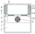
FIG. 2 is a schematic cross-sectional view of the housing of the present invention;
fig. 3 is a schematic top view of the structure of the present invention.
In the figure: 1. a housing; 2. a storage battery; 3. an induction coil; 4. a sensing module; 5. a partition plate; 6. an air outlet; 7. a filter screen; 8. a fixing frame; 9. a fixed seat; 10. a fan; 11. a vent hole; 12. a liquid crystal display screen; 13. a USB interface; 14. an opening; 15. a filter element; 16. a protective cover; 17. placing a rack; 18. a connecting rod; 19. a splint; 20. a spring.
Detailed Description
The technical solutions in the embodiments of the present invention will be clearly and completely described below with reference to the drawings in the embodiments of the present invention, and it is obvious that the described embodiments are only a part of the embodiments of the present invention, and not all of the embodiments. All other embodiments, which can be derived by a person skilled in the art from the embodiments given herein without making any creative effort, shall fall within the protection scope of the present invention.
Referring to fig. 1-3, a novel wireless charging mobile power supply comprises a casing 1, a groove is formed in the front of the casing 1, a liquid crystal display 12 is fixedly connected to an inner cavity of the groove, the use condition of the mobile power supply can be better observed by arranging the groove and the liquid crystal display 12, the right side of the casing 1 is provided with three USB interfaces 13, the equipment without wireless charging function can be better charged by arranging the USB interfaces 13, the right side of the casing 1 is hinged with a protective cover 16 through a hinge, the casing 1 is protected by arranging the protective cover 16, a placing frame 17 is fixedly connected to the back of the protective cover 16, holes are formed in the top and the bottom of the two sides of the placing frame 17, connecting rods 18 are slidably connected to inner cavities of the placing frame 17, and clamping plates 19 are fixedly connected to the connecting rods 18, a spring 20 is arranged between one side of the clamping plate 19 and the placing frame 17, the spring 20 is sleeved on the surface of the connecting rod 18, the mobile phone can be better stored and better charged by matching the placing frame 17, the connecting rod 18, the clamping plate 19 and the spring 20, the bottom of the inner cavity of the shell 1 is fixedly connected with the storage battery 2, the back of the inner cavity of the shell 1 and the upper part of the storage battery 2 are fixedly connected with the induction coil 3, the left side of the inner cavity of the shell 1 and the upper part of the storage battery 2 are fixedly connected with the induction module 4, a baffle plate 5 is fixedly connected between the top parts at two sides of the inner cavity of the shell 1, two sides of the top part of the baffle plate 5 are both provided with openings 14, the inner cavity of the opening 14 is fixedly connected with the filter element 15, the components in the inner cavity of the shell 1 can be better, inner chamber fixedly connected with filter screen 7 of air outlet 6, the fixed frame 8 of the equal fixedly connected with in both sides of the 1 inner chamber of casing, fixedly connected with fixing base 9 between the top of fixed frame 8 inner chamber and the bottom, inner chamber fixedly connected with fan 10 of fixing base 9, ventilation hole 11 has been seted up to one side that casing 1 was kept away from to fixed frame 8, through casing 1, battery 2, induction coil 3, induction module 4, baffle 5, air outlet 6, filter screen 7, fixed frame 8, fixing base 9, the cooperation use of fan 10 and ventilation hole 11, the good mesh of radiating effect has been realized, the practicality and the usability of device have been improved, mobile power source's life has been prolonged, the loss of property and the waste of resource have been reduced, user's use experience has been strengthened, thereby can be better satisfy user's user.
During the use, open fan 10, use through the cooperation of air outlet 6, filter screen 7, ventilation hole 11, opening 14 and filter core 15, carry out the heat dissipation to the inner chamber of casing 1 and handle, use through induction coil 3 and induction module 4's cooperation, therefore the purpose that charge efficiency is high has been reached, pulling connecting rod 18, connecting rod 18 drives and removes about splint 19, splint 19 extrudes spring 20, spring 20 receives the extrusion and produces the counterforce, thereby the good mesh of radiating effect has been realized.
Although embodiments of the present invention have been shown and described, it will be appreciated by those skilled in the art that changes, modifications, substitutions and alterations can be made in these embodiments without departing from the principles and spirit of the invention, the scope of which is defined in the appended claims and their equivalents.
Claims (5)
1. The utility model provides a novel wireless portable power source that charges, includes casing (1), its characterized in that: the bottom of the inner cavity of the shell (1) is fixedly connected with a storage battery (2), the back of the inner cavity of the shell (1) and the upper part of the storage battery (2) are fixedly connected with an induction coil (3), an induction module (4) is fixedly connected on the left side of the inner cavity of the shell (1) and above the storage battery (2), a clapboard (5) is fixedly connected between the tops of the two sides of the inner cavity of the shell (1), the top parts of the two sides of the shell (1) are both provided with air outlets (6), the inner cavity of each air outlet (6) is fixedly connected with a filter screen (7), both sides of the inner cavity of the shell (1) are fixedly connected with fixed frames (8), a fixed seat (9) is fixedly connected between the top and the bottom of the inner cavity of the fixed frame (8), the inner chamber fixedly connected with fan (10) of fixing base (9), ventilation hole (11) have been seted up to one side that casing (1) was kept away from in fixed frame (8).
2. The novel wireless charging mobile power supply of claim 1, characterized in that: the front of the shell (1) is provided with a groove, and an inner cavity of the groove is fixedly connected with a liquid crystal display screen (12).
3. The novel wireless charging mobile power supply of claim 1, characterized in that: the right side of casing (1) is provided with USB interface (13), and the quantity of USB interface (13) is three.
4. The novel wireless charging mobile power supply of claim 1, characterized in that: the opening (14) has all been seted up to the both sides at baffle (5) top, and the inner chamber fixedly connected with filter core (15) of opening (14).
5. The novel wireless charging mobile power supply of claim 1, characterized in that: the right side of casing (1) is articulated through the hinge and is had protection casing (16), the back fixedly connected with rack (17) of protection casing (16), the hole has all been seted up to the top and the bottom of rack (17) both sides, and the inner chamber sliding connection of hole has connecting rod (18), connecting rod (18) run through to the inner chamber and the fixedly connected with splint (19) of rack (17), be provided with spring (20) between one side of splint (19) and rack (17), the surface of connecting rod (18) is located to spring (20) cover.
Priority Applications (1)
| Application Number | Priority Date | Filing Date | Title |
|---|---|---|---|
| CN201911269244.9A CN110829614A (en) | 2019-12-12 | 2019-12-12 | Novel wireless charging mobile power supply |
Applications Claiming Priority (1)
| Application Number | Priority Date | Filing Date | Title |
|---|---|---|---|
| CN201911269244.9A CN110829614A (en) | 2019-12-12 | 2019-12-12 | Novel wireless charging mobile power supply |
Publications (1)
| Publication Number | Publication Date |
|---|---|
| CN110829614A true CN110829614A (en) | 2020-02-21 |
Family
ID=69544862
Family Applications (1)
| Application Number | Title | Priority Date | Filing Date |
|---|---|---|---|
| CN201911269244.9A Pending CN110829614A (en) | 2019-12-12 | 2019-12-12 | Novel wireless charging mobile power supply |
Country Status (1)
| Country | Link |
|---|---|
| CN (1) | CN110829614A (en) |
Cited By (2)
| Publication number | Priority date | Publication date | Assignee | Title |
|---|---|---|---|---|
| CN113472084A (en) * | 2021-07-09 | 2021-10-01 | 上海华源磁业股份有限公司 | Wireless transmitting coil and wireless charger |
| CN113746164A (en) * | 2021-08-18 | 2021-12-03 | 刘慧磊 | Wireless charging type mobile phone mobile power supply |
Citations (5)
| Publication number | Priority date | Publication date | Assignee | Title |
|---|---|---|---|---|
| CN207910495U (en) * | 2017-10-30 | 2018-09-25 | 三峡大学 | A kind of novel portable portable power source device |
| CN208174329U (en) * | 2018-05-30 | 2018-11-30 | 深圳市美诺尔电子有限公司 | A kind of mobile power source with heat sinking function |
| CN109038740A (en) * | 2018-08-14 | 2018-12-18 | 东莞市昱磁电子科技有限公司 | A kind of phone charger with wireless charging treasured |
| CN209233516U (en) * | 2018-12-18 | 2019-08-09 | 魏弋来 | A kind of novel radio mobile power source |
| CN210693568U (en) * | 2019-12-12 | 2020-06-05 | 深圳市金宇鸿科技有限公司 | Novel wireless charging mobile power supply |
-
2019
- 2019-12-12 CN CN201911269244.9A patent/CN110829614A/en active Pending
Patent Citations (5)
| Publication number | Priority date | Publication date | Assignee | Title |
|---|---|---|---|---|
| CN207910495U (en) * | 2017-10-30 | 2018-09-25 | 三峡大学 | A kind of novel portable portable power source device |
| CN208174329U (en) * | 2018-05-30 | 2018-11-30 | 深圳市美诺尔电子有限公司 | A kind of mobile power source with heat sinking function |
| CN109038740A (en) * | 2018-08-14 | 2018-12-18 | 东莞市昱磁电子科技有限公司 | A kind of phone charger with wireless charging treasured |
| CN209233516U (en) * | 2018-12-18 | 2019-08-09 | 魏弋来 | A kind of novel radio mobile power source |
| CN210693568U (en) * | 2019-12-12 | 2020-06-05 | 深圳市金宇鸿科技有限公司 | Novel wireless charging mobile power supply |
Cited By (2)
| Publication number | Priority date | Publication date | Assignee | Title |
|---|---|---|---|---|
| CN113472084A (en) * | 2021-07-09 | 2021-10-01 | 上海华源磁业股份有限公司 | Wireless transmitting coil and wireless charger |
| CN113746164A (en) * | 2021-08-18 | 2021-12-03 | 刘慧磊 | Wireless charging type mobile phone mobile power supply |
Similar Documents
| Publication | Publication Date | Title |
|---|---|---|
| EP2685542B1 (en) | Mobile charger | |
| CN210693568U (en) | Novel wireless charging mobile power supply | |
| CN204190474U (en) | A kind of portable multifunctional portable power source | |
| CN110829614A (en) | Novel wireless charging mobile power supply | |
| CN201846376U (en) | Charging mobile phone cover | |
| CN210273549U (en) | Portable power supply | |
| KR200473025Y1 (en) | Portable external power-supplying device | |
| CN205319748U (en) | Multipurpose of taking champignon function treasured that charges | |
| CN207010302U (en) | The portable high power portable power source of exportable 220V alternating currents | |
| CN211579674U (en) | Multifunctional mobile power supply | |
| CN214045704U (en) | Wireless charging mobile phone support | |
| CN201831146U (en) | Charging mobile phone sleeve | |
| KR20140037346A (en) | Automatic solar charging stand for mobile | |
| CN210196076U (en) | Fan base with charging function | |
| CN209930015U (en) | Portable energy storage power supply with protection architecture | |
| CN207670003U (en) | A kind of portable printing equipment | |
| CN208190296U (en) | A kind of portable lithium battery charge power supply | |
| CN210577831U (en) | Portable combination portable power source | |
| CN216252239U (en) | Multifunctional energy-saving mobile power supply | |
| CN217741355U (en) | Outdoor direct current power supply | |
| CN220086213U (en) | Power supply for communication equipment | |
| CN220934300U (en) | Portable energy storage power supply | |
| CN210693513U (en) | High-power mobile power supply | |
| CN209709731U (en) | A kind of novel mobile power source | |
| CN215071732U (en) | Simple structure is convenient for multi-functional portable power source of assembly |
Legal Events
| Date | Code | Title | Description |
|---|---|---|---|
| PB01 | Publication | ||
| PB01 | Publication | ||
| SE01 | Entry into force of request for substantive examination | ||
| SE01 | Entry into force of request for substantive examination |