CN110822965B - Method for controlling loop heat pipe water level through mobile phone APP - Google Patents
Method for controlling loop heat pipe water level through mobile phone APP Download PDFInfo
- Publication number
- CN110822965B CN110822965B CN201911218938.XA CN201911218938A CN110822965B CN 110822965 B CN110822965 B CN 110822965B CN 201911218938 A CN201911218938 A CN 201911218938A CN 110822965 B CN110822965 B CN 110822965B
- Authority
- CN
- China
- Prior art keywords
- water level
- air
- heat pipe
- water
- client
- Prior art date
- Legal status (The legal status is an assumption and is not a legal conclusion. Google has not performed a legal analysis and makes no representation as to the accuracy of the status listed.)
- Active
Links
Images


Classifications
-
- F—MECHANICAL ENGINEERING; LIGHTING; HEATING; WEAPONS; BLASTING
- F28—HEAT EXCHANGE IN GENERAL
- F28D—HEAT-EXCHANGE APPARATUS, NOT PROVIDED FOR IN ANOTHER SUBCLASS, IN WHICH THE HEAT-EXCHANGE MEDIA DO NOT COME INTO DIRECT CONTACT
- F28D15/00—Heat-exchange apparatus with the intermediate heat-transfer medium in closed tubes passing into or through the conduit walls ; Heat-exchange apparatus employing intermediate heat-transfer medium or bodies
- F28D15/02—Heat-exchange apparatus with the intermediate heat-transfer medium in closed tubes passing into or through the conduit walls ; Heat-exchange apparatus employing intermediate heat-transfer medium or bodies in which the medium condenses and evaporates, e.g. heat pipes
- F28D15/0266—Heat-exchange apparatus with the intermediate heat-transfer medium in closed tubes passing into or through the conduit walls ; Heat-exchange apparatus employing intermediate heat-transfer medium or bodies in which the medium condenses and evaporates, e.g. heat pipes with separate evaporating and condensing chambers connected by at least one conduit; Loop-type heat pipes; with multiple or common evaporating or condensing chambers
-
- F—MECHANICAL ENGINEERING; LIGHTING; HEATING; WEAPONS; BLASTING
- F28—HEAT EXCHANGE IN GENERAL
- F28D—HEAT-EXCHANGE APPARATUS, NOT PROVIDED FOR IN ANOTHER SUBCLASS, IN WHICH THE HEAT-EXCHANGE MEDIA DO NOT COME INTO DIRECT CONTACT
- F28D15/00—Heat-exchange apparatus with the intermediate heat-transfer medium in closed tubes passing into or through the conduit walls ; Heat-exchange apparatus employing intermediate heat-transfer medium or bodies
- F28D15/02—Heat-exchange apparatus with the intermediate heat-transfer medium in closed tubes passing into or through the conduit walls ; Heat-exchange apparatus employing intermediate heat-transfer medium or bodies in which the medium condenses and evaporates, e.g. heat pipes
- F28D15/04—Heat-exchange apparatus with the intermediate heat-transfer medium in closed tubes passing into or through the conduit walls ; Heat-exchange apparatus employing intermediate heat-transfer medium or bodies in which the medium condenses and evaporates, e.g. heat pipes with tubes having a capillary structure
- F28D15/043—Heat-exchange apparatus with the intermediate heat-transfer medium in closed tubes passing into or through the conduit walls ; Heat-exchange apparatus employing intermediate heat-transfer medium or bodies in which the medium condenses and evaporates, e.g. heat pipes with tubes having a capillary structure forming loops, e.g. capillary pumped loops
-
- F—MECHANICAL ENGINEERING; LIGHTING; HEATING; WEAPONS; BLASTING
- F28—HEAT EXCHANGE IN GENERAL
- F28D—HEAT-EXCHANGE APPARATUS, NOT PROVIDED FOR IN ANOTHER SUBCLASS, IN WHICH THE HEAT-EXCHANGE MEDIA DO NOT COME INTO DIRECT CONTACT
- F28D15/00—Heat-exchange apparatus with the intermediate heat-transfer medium in closed tubes passing into or through the conduit walls ; Heat-exchange apparatus employing intermediate heat-transfer medium or bodies
- F28D15/02—Heat-exchange apparatus with the intermediate heat-transfer medium in closed tubes passing into or through the conduit walls ; Heat-exchange apparatus employing intermediate heat-transfer medium or bodies in which the medium condenses and evaporates, e.g. heat pipes
- F28D15/06—Control arrangements therefor
Abstract
The invention provides a method for controlling loop heat pipe water level by a mobile phone APP, which comprises the following steps: 1) measuring the water level in the water storage condensation chamber; 2) the controller collects water level data and transmits the water level data to the cloud server; 3) the cloud server transmits the water level data to the APP client; 4) the client inputs operation parameters according to the water level data at the APP client; 5) the APP client transmits the operation parameters to the cloud server; 6) and the cloud server transmits the operation parameters to the controller. According to the invention, the water level of the heat exchange system is monitored through the mobile phone APP, so that the intelligent control of the remote monitoring heat exchange system is realized, and the damage caused by overhigh water level is avoided.
Description
The invention relates to a divisional application of a loop heat pipe heat exchange device intelligently controlled by a mobile phone APP water level, which is applied for No. 06, No. 2018101159278, No. 2018 of the application date.
Technical Field
The invention relates to a heat exchange system utilizing a reverse loop heat pipe.
Background
In the prior art, the heat pipe generally depends on gravity to realize the circulation of the heat pipe, but the heat pipe is only suitable for the condition of heat absorption at the lower part and heat release at the upper part, but cannot be suitable for the condition of heat absorption at the upper part and heat release at the lower part. Therefore, the invention improves the situation and invents the antigravity heat pipe.
The data show that the content of the vaporous water on the earth is 11.6 times that of the liquid freshwater on the earth surface, but the utilization rate of the vaporous freshwater is not high. The existing air water taking method mainly converts water resources existing in the form of water vapor or tiny water drops in wet air into liquid water, and mainly comprises a refrigeration condensation method, an adsorption method, a mechanical compression method, a semiconductor refrigeration method and the like. The technical scheme includes that a mature solar semiconductor refrigeration water taking device with a heat regenerator is provided by Tantao et al, and is shown in CN2567274Y and CN10485506A, and numerical simulation and experimental tests are carried out on the solar semiconductor refrigeration water taking device, but the scheme has two defects that on one hand, a solar storage battery is low in conversion efficiency and large in loss, on the other hand, the solar storage battery is limited by more regions and natural conditions, and the water taking device is complex in structure.
The applicant has already filed for the reverse gravity heat pipe in a previous application, but in research, the water storage is too much or too little, and intelligent heat exchange cannot be realized. Aiming at the problems, the invention improves on the basis of the prior invention, provides a new loop heat pipe heat exchange system and improves the intelligent function of the system.
Disclosure of Invention
The invention provides a novel loop heat pipe heat exchange device, which has the advantages of compact structure and good heat exchange effect, and can effectively increase the air heat exchange area and obviously improve the cooling efficiency.
In order to achieve the purpose, the technical scheme of the invention is as follows:
a reverse loop heat pipe heat exchange system capable of intelligently controlling air flow according to water level comprises a fan, an air inlet channel, an air outlet channel, a loop heat pipe and a water storage condensation chamber, and is characterized in that the water storage condensation chamber is arranged in a soil cold source, the loop heat pipe is an antigravity heat pipe, an outlet of the air inlet channel and an inlet of the air outlet channel are communicated with the water storage condensation chamber, the fan device exchanges heat with an evaporation end in the process of introducing air into the water storage condensation chamber from the air inlet channel, and the condensation end conducts heat to an external soil cold source; the heat exchange system also comprises a motor, a water level sensor and a central controller, wherein the water level sensor is arranged in the water storage condensation chamber and used for measuring the water level in the water storage condensation chamber, the air is introduced from the air inlet channel, the motor is connected with the fan and drives the fan to rotate, the motor and the water level sensor are in data connection with the central controller, and the central controller automatically controls the frequency of the motor according to the detected water level data so as to control the air flow entering the heat exchange system; the central controller is connected with the cloud server, the cloud server is connected with the client, the controller transmits water level data and motor frequency data measured by the water level sensor to the cloud server, the water level data and the motor frequency data are transmitted to the client through the cloud server, the client is a mobile phone, an APP program is installed on the mobile phone, a user can select an automatic control or manual control working mode at the client, and the controller controls the frequency of the motor according to the working mode selected by the control client.
Preferably, in a manual control working mode, a user obtains water level data and motor frequency data according to a client, the motor frequency is manually input at the client and then transmitted to the central controller through the cloud server, and the central controller controls the motor frequency to work according to the frequency input by the client.
Preferably, in an automatic control operating mode, the controller automatically controls the frequency of the motor according to the detected water level data, so as to control the air flow entering the heat exchange system, and transmit the water level data and the frequency data to the client.
Preferably, the controller automatically turns on the rotation of the motor if the detected water level data is lower than a first value, and stops the rotation of the motor if the measured pressure data is higher than a second value, which is greater than the first value.
Preferably, when the measured water level is lower than a first water level, the motor drives the fan to rotate at a first power; when the measured water level is higher than a second water level higher than the first water level, the motor rotates at a second power lower than the first power; when the measured water level is higher than a third water level higher than the second water level, the motor rotates at a third power lower than the second power; when the measured water level is higher than a fourth water level higher than the third water level, the motor rotates at a fourth power lower than the third power; when the measured water level is higher than a fifth water level higher than the fourth water level, the motor is rotated at a fifth power lower than the fourth power.
Preferably, the first water level is 0.88 to 0.93 times the second water level, the second water level is 0.88 to 0.93 times the third water level, the third water level is 0.88 to 0.93 times the fourth water level, and the fourth water level is 0.88 to 0.93 times the fifth water level.
Preferably, the fifth power is 0.8 to 0.9 times the fourth power, the fourth power is 0.8 to 0.9 times the third power, the third power is 0.8 to 0.9 times the second power, and the second power is 0.8 to 0.9 times the first power.
Preferably, a pipeline of the condensation end flowing to the evaporation end is arranged between and in contact with two adjacent vertical fins, and the outer wall surface of the evaporation end is provided with longitudinal vertical fins in a surrounding manner; the air outlet channel is arranged between and in contact with two adjacent vertical fins; the descending tube of the heat pipe is arranged between and contacted with the two adjacent vertical fins; at least a portion of the upleg and downleg are disposed within the air inlet passage; the pipeline is a plurality of, the air outlet passageway is a plurality of, the pipeline equals with the quantity of air outlet passageway.
Preferably, the vertical fin extends through a center of the air inlet passage, and the up-leg pipe has the same center as the inlet pipe of the condensing chamber.
Preferably, the number of the pipelines is multiple, and the distances between the circle centers of the pipelines and the ascending sections are the same.
Preferably, a pipeline is arranged between every two adjacent vertical fins, and the pipelines are in a parallel structure.
Preferably, the number of the air outlet channels is multiple, and the distance between the circle center of the air outlet channels and the evaporation end pipeline is the same.
Preferably, an air outlet channel is arranged between every two adjacent vertical fins, and the air outlet channels are in a parallel structure.
Preferably, the number of the pipelines is multiple, the number of the air outlet channels is multiple, and the number of the pipelines and the number of the air outlet channels are equal.
Preferably, the center of the pipeline is the same distance with the center of the adjacent air outlet channel; the center of the air outlet channel is the same distance with the center of the adjacent air pipeline.
Preferably, the radius of the air outlet channel is R, the radius of the pipeline is R, and the included angle between adjacent fins is A, so that the following requirements are met:
sin (a) = a × LN (R/R) + b, where LN is a logarithmic function, a, b are parameters,
wherein 0.330< a <0.340,0.73< b < 0.74;
15°<A<25°;
0.24< r/R<0.5。
preferably, 0.26< R/R < 0.38.
The utility model provides a loop heat pipe water intaking device of air, includes fan unit, air inlet passageway, air outlet passageway, loop heat pipe and water storage condensation chamber, its characterized in that, the water storage condensation chamber sets up in the soil cold source, the loop heat pipe is antigravity heat pipe, and the evaporating end of loop heat pipe is installed in water storage condensation chamber entrance, and the export of air inlet passageway, air outlet passageway's entry and water storage condensation chamber intercommunication, the fan unit introduces the in-process and the evaporating end of water storage condensation chamber with the air from air inlet passageway and carries out the heat transfer, and the condensing end gives outside soil cold source with heat-conduction.
Preferably, the fan device comprises a vertical wind turbine, a planet wheel speed increaser and a helical blade, and the vertical wind turbine drives the planet wheel speed increaser and the helical blade to suck air by using wind energy.
Preferably, the lower end of the helical blade is communicated with an inlet pipe of the water storage condensation chamber, and the diameter of the position of the water storage condensation chamber connected with the inlet pipe is increased and then is decreased.
Preferably, the evaporation end of the loop heat pipe is arranged on the inlet pipe of the water storage condensation chamber, and the condensation end of the loop heat pipe is wound outside the condensation chamber and is in direct contact with the external soil.
Preferably, the air inlet channel is an inlet pipe of the condensing chamber, the air outlet channel is provided in the inlet pipe of the condensing chamber, and the cold air from the air outlet precools the hot air from the air inlet.
Preferably, at least one part of the evaporation end is arranged in the inlet pipe of the condensation chamber, at least one part of the evaporation end is filled with the capillary core, the center of the capillary core is provided with a pipeline from the condensation end to the evaporation end, and the outer wall surface of the ascending section of the evaporation end is provided with longitudinal vertical fins in a surrounding mode.
Compared with the prior art, the invention has the following advantages:
1) according to the invention, through the mobile phone APP client, the automatic control of the water level of the heat exchange system is realized through the controller, the energy is saved, the optimal efficiency is achieved, the intellectualization of the heat exchange system is improved, the remote control is realized, the constant water level of the water storage condensation chamber can be kept, the frequency of the fan is automatically adjusted according to the water temperature height, and the reduction of the heat exchange efficiency caused by overhigh or overlow pressure is avoided.
2) Through vertical fin, increase the heat transfer effect on the one hand, on the other hand plays the effect of fixed pipeline and heat pipe.
3) The temperature difference between the above-ground air and the underground soil is utilized to force the wet air to reach the dew point, so that the dependence on electricity is eliminated, zero emission and zero pollution can be really realized.
4) The loop heat pipe is used as an efficient heat transfer tool, has a simple principle and a compact structure, can effectively increase the air heat exchange area, and obviously improves the cooling efficiency.
5) The loop heat pipe condenser is wound outside the condensing chamber and fully contacts with external soil, so that heat dissipation of air at the evaporation end of the heat pipe is increased, and cooling efficiency is improved.
6) The system adopts a vertical axis wind turbine for wind power generation, avoids the influence of wind direction on the wind turbine, can collect wind in all directions, and can drive the air inlet impeller to rotate under the windless condition, so that the device can continuously operate. Wind-light complementation is achieved in a certain sense.
Drawings
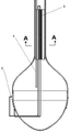
Fig. 1 is a schematic view of the overall structure of the present invention.
FIG. 2 is a schematic view of a vertical axis wind turbine according to the present invention.
Fig. 3 is a cross-sectional view of the planetary gear speed increaser of the present invention.
Fig. 4 is a top view of the impeller of the present invention.
FIG. 5 is a view of a subterranean portion of the present invention.
Fig. 6 is a sectional view of a condensing chamber of the present invention.
Fig. 7 is a cross-sectional view a-a of fig. 6.
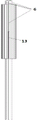
Fig. 8 is a schematic structural diagram of a heat pipe according to the present invention.
Fig. 9 is a schematic diagram of a multi-evaporation-end to condensation-end pipeline (descending section) according to the present invention.
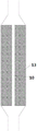
Fig. 10 is a schematic view of a tube connection structure for providing a capillary wick according to the present invention.
FIG. 11 is a schematic view of a flow-controlled pipeline connection structure according to the present invention.
Fig. 12 is a control flowchart of fig. 11.
The reference numbers are as follows: the heat pump type heat pump air conditioner comprises a fan 1, a planet wheel speed changer 2, a helical blade 3, an air outlet channel 4, an air inlet channel 5, a loop heat pipe evaporation end 6, a condensation chamber 7, a loop heat pipe condensation end 8, an evaporation end 9 flowing to a condensation end pipeline (descending section), a condensation end 10 flowing to an evaporation end pipeline, a condensation chamber inlet pipe 11, a fin 12, a capillary core 13, a motor 14 and a central controller 15.
Detailed Description
The following detailed description of embodiments of the invention refers to the accompanying drawings.
In this document, "/" denotes division and "×", "denotes multiplication, referring to formulas, if not specifically stated.
An antigravity loop heat pipe, as shown in fig. 8, comprises an evaporation end 6 and a condensation end 8, wherein the evaporation end 6 is located above the condensation end 8, a part of the evaporation end 6 is arranged in a fluid rising section, and a capillary wick 13 is arranged at least in a part of the evaporation end of the fluid rising section, as shown in fig. 10.
Preferably, the evaporation end comprises two parts, namely an evaporation end flow direction condensation end pipeline (descending section) 9 and an ascending section. Preferably, a condensation end flow to the evaporation end line 10 is arranged in the rising section.
As shown in fig. 1, a loop heat pipe air heat exchange system includes a fan device 1, an air inlet channel 5, an air outlet channel 4, a loop heat pipe and a water storage condensation chamber 7, the water storage condensation chamber 7 is disposed in a soil cold source, the loop heat pipe is an antigravity heat pipe, an outlet of the air inlet channel 5 and an inlet of the air outlet channel 4 are communicated with the water storage condensation chamber, the fan device 1 exchanges heat with an evaporation end 6 in a process of introducing air from the air inlet channel 5 into the water storage condensation chamber 7, and a condensation end 8 conducts heat to an external soil cold source.
The invention provides an air water taking device of a loop heat pipe with a novel structure, and the loop heat pipe is used as a high-efficiency heat transfer tool, so that the air water taking device is simple in principle and compact in structure, and the cooling efficiency is obviously improved. The invention forces the wet air to reach the dew point by utilizing the temperature difference between the above-ground air and the underground soil, gets rid of the dependence on electricity, and can really realize zero emission and zero pollution.
Preferably, at least one part of the evaporation end 6 of the loop heat pipe is arranged at the inlet of the water storage condensation chamber 7.
Preferably, a condensing chamber 7 inlet pipe is provided between the condensing chamber 7 and the blower device 1, at least a portion of the air inlet passage 5 is provided in the condensing chamber 7 inlet pipe, and at least a portion of the condensing chamber 7 inlet pipe is provided in the external soil cooling source. Through so setting up, can make the air in the air inlet passage 5 directly participate in the heat transfer of outside soil cold source, make the air under the combined action of soil and loop heat pipe, further cool off, improve the cooling effect.
Further preferably, the fan device 1 includes a vertical wind turbine, a planet wheel speed increaser 2 and a helical blade 3, and the vertical wind turbine drives the planet wheel speed increaser 2 and the helical blade 3 to suck air by using wind energy.
Preferably, the vertical wind turbine 1 is positioned at the top end, and the lower part is sequentially provided with a planetary gear speed increaser 2 and a helical blade 3, and the helical blade 3 is communicated with an inlet pipe of a condensation chamber 7, so that external air is introduced into the condensation chamber 7.
Further preferably, the inlet pipe of the condensation chamber 7 is an air inlet channel.
Preferably, as shown in fig. 1, the diameter of the water storage condensation chamber 7 gradually increases from the position where the inlet pipe is connected to the lower portion, and then gradually decreases from the certain position. The air can flow in the condensing chamber, the gas circulation is completed, and the heat exchange efficiency between the gas and the wall of the condensing chamber is improved.
Preferably, the evaporation end 6 of the loop heat pipe is arranged on the inlet pipe of the water storage condensation chamber, and the condensation end 8 of the loop heat pipe is wound outside the condensation chamber and is in direct contact with the external soil. The loop heat pipe condenser is wound outside the condensing chamber and fully contacts with external soil, so that heat dissipation of air at the evaporation end of the heat pipe is increased, and cooling efficiency is improved.
Preferably, at least one part of the evaporation end 6 is provided with a capillary core 13, the capillary force of the capillary core provides power for the working medium to flow back and circulate, and meanwhile, the amount of the flowing back working medium meets the requirement of heat transfer, so that the effect of the antigravity heat pipe is realized.
By arranging the capillary wick 13, the capillary wick 13 is arranged at the evaporation end, so that the ascending section 6 of the evaporation end naturally generates flow resistance, and steam generated at the evaporation end naturally flows to the pipeline 9 with small resistance, thereby forming the antigravity heat pipe.
Preferably, the capillary wick 13 is only arranged in the rising section of the evaporation end, preferably in a part of the rising section. Such as shown in fig. 6 and 10.
Preferably, at least a part of the air outlet channel 4 is provided in the inlet duct of the condensation chamber, the cold air of the air outlet precooling the hot air of the air inlet. Through the heat exchange of outlet gas and inlet gas, further realize the heat transfer effect, increase the condensation efficiency of water.
Preferably, as shown in fig. 7, the evaporation end is disposed at the inlet pipe of the condensation chamber, the rising section of the evaporation end is filled with the capillary core 13 to provide a sufficient capillary force, the center of the capillary core 13 is provided with the pipeline 10 from the condensation end to the evaporation end, by disposing the pipeline 10 (without the capillary core), the fluid resistance of the pipeline can be reduced, the working medium flows back more smoothly, the heat transfer capability in the anti-gravity state is improved, the outer wall surface of the rising section of the evaporation end is provided with the longitudinal vertical fins 12 in a surrounding manner, the heat exchange area is increased, and the heat exchange efficiency with air is improved.
The pipeline 10 is a gas or liquid pipeline, and realizes flexible arrangement, namely the pipe diameter is small and the pipe is easy to bend. The principle of the loop heat pipe is that if the evaporator side and the pipeline 10 are steam pipelines, the principle is that the evaporator is heated and internal working media are evaporated, steam enters the pipeline 10 along the upper outlet of the evaporator, then flows to the pipeline surrounding the lower part and contacts with soil to start condensation, and after the steam is completely condensed, the steam returns to the evaporator under the capillary force of the capillary core of the evaporator, so that the circulation of the working media is realized.
Preferably, the tube 10 communicates with the capillary wick 13. Through the communication, the fluid communication between the capillary wick 13 and the pipeline 10 can be realized, so that if a large pressure is generated due to heat absorption during the liquid ascending through the capillary wick, for example, even bubbles can occur, the pressure of the evaporation section can be equalized through the pipeline 10, and thus the equalization of the pressure is ensured.
Further preferably, the capillary wick 13 extends to the condensation end so as to directly suck up the liquid at the condensation end. Further improving the circulation capacity of the antigravity heat pipe.
Preferably, the capillary wick is distributed along the height direction, as shown in fig. 6. Further preferably, the capillary force of the capillary wick is gradually increased along the height decreasing direction. The closer to the condensation end, the greater the capillary force. Experiments show that the suction force to the liquid can be further improved by adopting the mode, and the suction force can be improved by more than 20% at the same cost, so that the heat exchange effect is improved.
By further analysis, the primary reason may be that as the capillary force near the condensation end becomes larger, the liquid at the condensation end can be rapidly absorbed into the capillary wick, and the liquid continuously flows towards the evaporation end. In the flowing process, the liquid absorbs heat continuously, the temperature is increased due to heat absorption, the density is reduced, the required capillary force is obviously reduced due to density change, and the liquid can be easily sucked upwards under the condition of small capillary force. The reason for this is that the present inventors have conducted extensive experiments and studies, and are not common knowledge in the art.
Further preferably, the capillary force of the capillary wick increases gradually in the height decreasing direction to a larger and larger extent. Experiments show that the suction to liquid can be further improved by adopting the mode, and the suction about 8 percent can be further improved at the same cost, so that the heat exchange effect is improved.
Preferably, the pipeline is formed by a through hole formed in the middle of the capillary core.
Preferably, as shown in fig. 10, the pipe diameter of the heat pipe position where the capillary wick is provided is larger than the pipe diameter of the heat pipe position where the capillary wick is not provided.
Further preferably, as shown in fig. 10, the change in the tube diameter between the tube at the position of the heat pipe where the capillary wick is disposed and the tube at the position of the heat pipe where the capillary wick is not disposed is a continuous change. Further preferably a straight line variation. The pipe at the large pipe diameter position and the pipe through which the small pipe passes are connected at the joint by a contraction member. The change in the tube diameter of the constriction is a linear change.
Preferably, the air outlet channel 4 is arranged between and in contact with two adjacent vertical fins 12. Through so setting up, can reduce the mechanism that sets up independent support air outlet passage 4 for compact structure, outlet passage's cold air accessible pipeline and fin heat transfer keep the degree of coldness of fin, reinforcing heat transfer effect.
Preferably, the condensation end pipe 9 flowing to the evaporation end is arranged between and in contact with two adjacent vertical fins. Through so setting up, can reduce the mechanism that sets up independent support air outlet passage 4 for compact structure, the steam accessible pipeline in the pipeline is short for a short time a small amount of heat transfer to the fin, reduces the whole thermal resistance of system, avoids producing in the evaporimeter overheated under the antigravity condition on ground, slows down the temperature shock phenomenon in the heat pipe start-up process.
It is further preferred that the conduit 9 is closer to the outer wall of the evaporation end conduit than the air outlet channel 4, so that the two heat transfer processes described above can be carried out simultaneously, with corresponding effect.
Further preferably, the diameter of the conduit 9 is smaller than the air outlet passage 4.
Preferably, the condensation end pipeline 9 along which a plurality of evaporation end flow directions can be arranged, as shown in fig. 7 and 9. Through setting up a plurality of pipelines 9, can be so that the steam that the evaporation end endotherm produced gets into the condensation end through a plurality of pipelines 9, further strengthen heat transfer, because the fluid endotherm evaporation in the heat pipe leads to the volume to increase moreover, through setting up a plurality of pipelines 9, can further alleviate pressure, improve heat transfer effect.
Further preferably, the vertical fin extends through the center of the inlet pipe of the condensing chamber, and the evaporation end rising section pipeline and the inlet pipe of the condensing chamber have the same center.
Preferably, the number of the pipelines 9 is multiple, and the distance between the circle center of the multiple pipelines 9 and the pipeline at the ascending section of the evaporation end is the same.
Further preferably, one pipe 9 is arranged between every two adjacent vertical fins 12. The pipeline 9 is in a parallel structure.
Preferably, the number of the air outlet channels 4 is multiple, and the distance between the circle center of the air outlet channels 4 and the pipeline at the ascending section of the evaporation end is the same, so that the temperature distribution among the fins is more uniform, and the heat exchange effect is more obvious. It is further preferred that one air outlet channel 4 is provided between each adjacent two of the vertical fins 12. The air outlet channels 4 are of a parallel configuration.
Further preferably, there are a plurality of the pipelines 9, a plurality of the air outlet passages 4, and the number of the pipelines 9 and the number of the air outlet passages 4 are equal.
Further preferably, the pipe lines 9 are arranged between adjacent air outlet channels 4, the air outlet channels 4 being between adjacent pipe lines 9. Further preferably, the center of the pipeline 9 is the same distance with the center of the adjacent air outlet channel 4; the center of the air outlet passage 4 is at the same distance from the center of the adjacent air line 9. I.e. the pipe 9 is arranged in the middle of an adjacent air outlet channel 4, the air outlet channel 4 being in the middle of an adjacent pipe 9. As shown in fig. 8, a first connection line between the center of the pipeline 9 and the center of the evaporation end 6 forms a first connection line and a third connection line between the centers of the adjacent air outlet channels 4 and the center of the evaporation end 6, and a first included angle formed between the first connection line and the second connection line is equal to a second included angle formed between the first connection line and the third connection line. Similarly, a fourth connecting line is formed between the circle center of the air outlet channel 4 and the circle center of the evaporation end 6, a fifth connecting line and a sixth connecting line are formed between the circle centers of the adjacent pipelines 9 and the circle center of the evaporation end 6, and a third included angle formed between the fourth connecting line and the fifth connecting line is equal to a fourth included angle formed between the fourth connecting line and the sixth connecting line. I.e. in the circumferential direction, the pipe 9 and the outlet channel 4 are evenly distributed.
Through the arrangement, the pipeline 9 and the air outlet channel 4 can be ensured to uniformly cool the inlet air, and the uneven local income is avoided, so that the water taking effect is poor.
In numerical simulation and experiments, the pipe diameters of the air outlet channel 4 and the pipeline 9 are different from each other too much and not too small, if the pipe diameters are too large, the distance between the air outlet channel 4 and the pipeline 9 is too far, the air heat exchange between the channel 4 and the pipeline 9 is poor, the overall heat exchange is not uniform, if the pipe diameters are too small, the distance between the air outlet channel 4 and the pipeline 9 is too close, the air near the outer wall of the air inlet channel 5 and/or the air near the outer wall of the evaporation end 6 is poor, and the air heat exchange in the overall air inlet channel 5 is not uniform; the same reason, the contained angle between adjacent fin 12 can not be too big, it is too big can lead to the distribution fin few, the heat transfer effect is too good, lead to the quantity that air outlet passageway 4 and pipeline 9 distribute too little simultaneously, lead to the heat transfer inhomogeneous and the heat transfer effect is not good, on the same reason, the contained angle between adjacent fin 12 can not be too little, it is too dense to lead to the fin distribution if too little, the flow resistance greatly increases, and the pipe diameter of air outlet passageway 4 and pipeline 9 differs by a little, but their heat transfer ability of equal area is very big, therefore the heat transfer is inhomogeneous under this kind of condition, lead to the heat transfer effect not good. It is therefore necessary to determine the optimum dimensional relationship by extensive numerical simulations and experiments thereof.
The radius of the air outlet channel 4 is R, the radius of the pipeline 9 is R, the included angle between adjacent fins is A, and the following requirements are met:
sin (a) = a × LN (R/R) + b, where LN is a logarithmic function, a, b are parameters,
wherein 0.330< a <0.340,0.73< b < 0.74;
15°<A<25°;
0.24< R/R < 0.5; further preferably, 0.26< R/R < 0.38.
The empirical formula is obtained through a large number of numerical simulations and experiments, and the error is basically within 3.2 after experimental verification.
Preferably, said 3< R <10 mm; 1.5< r <4.0 mm;
further preferably, the pipe diameter of the heat pipe at the position where the capillary core is arranged is 30-40mm, and further preferably 32 mm;
further preferably, the pipe diameter of the heat pipe without the capillary core is 5.0-6.4 mm;
further preferably, the pipe diameter of the pipeline from the condensation end to the evaporation end is 5.0-6.4 mm;
further preferably, the pipe diameter of the air inlet channel 5 is 80-200mm, preferably, 120-150 mm;
further preferably, the length of the fins in the vertical direction is 780-1500mm, preferably 1200 mm; the length of the longitudinal extension of the fins is 95% of the difference between the outer diameter of the evaporation end 6 and the inner diameter of the air outlet channel 4. The overall heat exchange capacity of the fin is remarkably improved under the length, the heat exchange coefficient is also in a proper range, and the influence on the damage effect of the boundary layer and the fluid flowing effect is relatively small.
The external wind drives the vertical axis wind turbine 1 shown in the drawing to rotate, and the wind energy is converted into mechanical energy. The wind turbine drives the coaxial air inlet helical blade 3 to rotate through the planet wheel speed changer 2, and the filtered outside wet air is sucked into the condensation cavity. The air inlet is designed as a rotary body with a reducing opening for maintaining pressure. The continuous operation of the impeller increases the gas pressure in the chamber and the absolute humidity of the humid air. The air with larger absolute humidity enters the underground condensing chamber through the air inlet channel with relatively narrow caliber under the continuous action of air pressure. The external hot air exchanges heat with the cooler air which is discharged outdoors in the air outlet channel in the air inlet channel 5, so that partial heat is taken away by the waste gas, the metal outer wall which is in contact with the soil also has a heat conduction function, and the air precooling is completed under the combined action of the external hot air and the cooler air. After air begins to enter the condensation chamber, hotter air slowly passes through the fin channels of the loop heat pipe evaporator to exchange heat with the medium in the loop heat pipe, the temperature of the warmer air is obviously reduced, and when the dew point is reached, water vapor begins to liquefy to form small liquid drops on the surfaces of the fins. The residual air goes deep into the water storage condensation chamber 7, exchanges heat with the external soil through the metal outer wall of the cavity, and is condensed into liquid drops. As the liquid water is gradually accumulated, the contact area of the hot air and the outer wall is gradually reduced, and the main cold source is provided by the loop heat pipe. The evaporation end 6 of the loop heat pipe absorbs the heat of the hot air, the liquid working medium is evaporated into a gas state, then the heat is conducted to the external soil through the loop heat pipe condensation end 8 wound outside the condensation chamber, the gas working medium is condensed into a liquid state, and the antigravity loop heat pipe has the characteristic of enabling the liquid to flow back. Under the continuous wind power, water resources in the external wet air are continuously collected into the water storage condensation chamber, are rapidly cooled, and are discharged after liquid water is condensed. The electric energy generated by the vertical axis wind turbine 1 is stored in the storage battery, and the electric energy is supplied to the electronic water pump to pump out the accumulated fresh water and is stored in the ground water tank.
When water is taken, the water vapor in the air is condensed and taken by means of the wind energy, the soil cold source and the loop heat pipe, so that the dependence of the traditional solar adsorption method on the solar energy is solved, the solar adsorption method is suitable for more regions and weather conditions, no secondary energy consumption is realized, and the problem of low conversion efficiency in the prior art is solved.
Preferably, the planet wheel speed increaser is connected with the vertical shaft wind turbine and the impeller, and amplifies the rotating speed transmitted by the wind turbine to the impeller, so that the outside air enters the tank body more quickly, the air inlet volume is increased to a certain extent, and the pressure in the pipeline is increased.
Preferably, the loop heat pipe capillary wick is prepared by using a powder metallurgy method. Before starting, the capillary core, the supplement cavity and the liquid conveying pipe of the evaporator of the loop heat pipe are filled with working medium, and the steam channel, the condenser and the steam pipe are in two-phase states.
The cooling chamber part adopts a cooperative heat exchange mode of taking soil cooling as an auxiliary and taking an antigravity loop heat pipe as a main, so that the air cooling speed can be greatly improved, and the water yield can be improved.
Preferably, the condensation end of the loop heat pipe is wound outside the condensation chamber, so that the heat dissipation area is increased.
Preferably, the exhaust pipe is placed in the intake passage, thereby achieving the purpose of precooling the air.
As a preferred embodiment, the invention can be provided with a motor to drive the fan to rotate.
Preferably, the water intake device (heat exchange system) further comprises a motor 14, a pressure sensor and a central controller 15, the water level sensor is disposed in the water storage condensation chamber and used for measuring the water level in the water storage condensation chamber, the fan introduces air from the air inlet channel, the motor 14 is connected to the fan 1 to drive the fan 1 to rotate, the motor 1 and the water level sensor are in data connection with the central controller 15, the central controller 15 is connected to the cloud server 16, the cloud server 16 is connected to the client 17, wherein the controller 15 transmits the water level data and the motor frequency data measured by the water level sensor to the cloud server 16 and then transmits the data to the client through the cloud server 16, the client is a mobile phone, the mobile phone is equipped with an APP program, and a user can select an automatic control or manual control work mode at the client, the controller controls the frequency of the motor in accordance with the operating mode selected by the control client.
According to the invention, the water level of the heat exchange system is automatically controlled through the mobile phone APP client and the controller, so that energy is saved, the best efficiency is achieved, the intellectualization of the heat exchange system is improved, and the remote control is realized.
Preferably, in a manual control working mode, a user obtains water level data and motor frequency data according to a client, the motor frequency is manually input at the client and then transmitted to the central controller through the cloud server, and the central controller controls the motor frequency to work according to the frequency input by the client.
Preferably, in an automatic control operating mode, the controller automatically controls the frequency of the motor according to the detected water level data, so as to control the air flow entering the heat exchange system, and transmit the water level data and the frequency data to the client.
Preferably, in the automatic control operation mode, the controller automatically turns on the rotation of the motor if the detected water level data is lower than a first value, and stops the rotation of the motor if the measured pressure data is higher than a second value, which is greater than the first value.
Preferably, when the measured water level is lower than the first water level, the motor drives the fan to rotate with first power; when the measured water level is higher than a second water level higher than the first water level, the motor rotates at a second power lower than the first power; when the measured water level is higher than a third water level higher than the second water level, the motor rotates at a third power lower than the second power; when the measured water level is higher than a fourth water level higher than the third water level, the motor rotates at a fourth power lower than the third power; when the measured water level is higher than a fifth water level higher than the fourth water level, the motor is rotated at a fifth power lower than the fourth power.
Further preferably, the first water level is 0.88 to 0.93 times the second water level, the second water level is 0.88 to 0.93 times the third water level, the third water level is 0.88 to 0.93 times the fourth water level, and the fourth water level is 0.88 to 0.93 times the fifth water level.
The invention provides an intelligent water level control loop heat pipe heat exchange system which can keep the water level of a water storage condensation chamber constant, automatically adjust the frequency of a fan according to the water temperature height and avoid the reduction of heat exchange efficiency caused by overhigh or overlow pressure.
The water intake device comprises a water diversion pipeline. When the water level is too high, the water is led out from the water storage condensation chamber by the water conduit for utilization.
Although the present invention has been described with reference to the preferred embodiments, it is not limited thereto. Various changes and modifications may be effected therein by one skilled in the art without departing from the spirit and scope of the invention as defined in the appended claims.
Claims (2)
1. A method for controlling the water level of a loop heat pipe air water taking device through a mobile phone APP comprises a heat exchange system, wherein the heat exchange system comprises an air inlet channel, an air outlet channel, a loop heat pipe and a water storage condensation chamber, the water storage condensation chamber is arranged in a soil cold source, the air outlet channel is arranged in the air inlet channel, the loop heat pipe is an antigravity heat pipe, an outlet of the air inlet channel and an inlet of the air outlet channel are communicated with the water storage condensation chamber, a fan device conducts heat with an evaporation end in the process of introducing air into the water storage condensation chamber from the air inlet channel, and the condensation end conducts the heat to an external soil cold source; the loop heat pipe comprises an evaporation end and a condensation end, the evaporation end comprises a descending section and an ascending section, the descending section and the ascending section are communicated with a pipeline of the condensation end, and at least one part of the ascending section is provided with a capillary core; the method comprises the following steps:
1) measuring the water level in the water storage condensation chamber;
2) the controller collects water level data and transmits the water level data to the cloud server;
3) the cloud server transmits the water level data to the APP client;
4) the client inputs operation parameters according to the water level data at the APP client;
5) the APP client transmits the operation parameters to the cloud server;
6) the cloud server transmits the operation parameters to the controller;
7) the motor operates according to instructions given by the controller.
2. The method of claim 1, wherein the user can select an automatic or manual mode of operation at the client, and the controller controls the frequency of the motor based on the mode of operation selected by the control client.
Priority Applications (1)
| Application Number | Priority Date | Filing Date | Title |
|---|---|---|---|
| CN201911218938.XA CN110822965B (en) | 2018-02-06 | 2018-02-06 | Method for controlling loop heat pipe water level through mobile phone APP |
Applications Claiming Priority (2)
| Application Number | Priority Date | Filing Date | Title |
|---|---|---|---|
| CN201911218938.XA CN110822965B (en) | 2018-02-06 | 2018-02-06 | Method for controlling loop heat pipe water level through mobile phone APP |
| CN201810115927.8A CN109520344B (en) | 2018-02-06 | 2018-02-06 | Loop heat pipe heat exchange device intelligently controlled by APP water level of mobile phone |
Related Parent Applications (1)
| Application Number | Title | Priority Date | Filing Date |
|---|---|---|---|
| CN201810115927.8A Division CN109520344B (en) | 2018-02-06 | 2018-02-06 | Loop heat pipe heat exchange device intelligently controlled by APP water level of mobile phone |
Publications (2)
| Publication Number | Publication Date |
|---|---|
| CN110822965A CN110822965A (en) | 2020-02-21 |
| CN110822965B true CN110822965B (en) | 2021-12-17 |
Family
ID=65769749
Family Applications (2)
| Application Number | Title | Priority Date | Filing Date |
|---|---|---|---|
| CN201810115927.8A Expired - Fee Related CN109520344B (en) | 2018-02-06 | 2018-02-06 | Loop heat pipe heat exchange device intelligently controlled by APP water level of mobile phone |
| CN201911218938.XA Active CN110822965B (en) | 2018-02-06 | 2018-02-06 | Method for controlling loop heat pipe water level through mobile phone APP |
Family Applications Before (1)
| Application Number | Title | Priority Date | Filing Date |
|---|---|---|---|
| CN201810115927.8A Expired - Fee Related CN109520344B (en) | 2018-02-06 | 2018-02-06 | Loop heat pipe heat exchange device intelligently controlled by APP water level of mobile phone |
Country Status (1)
| Country | Link |
|---|---|
| CN (2) | CN109520344B (en) |
Citations (7)
| Publication number | Priority date | Publication date | Assignee | Title |
|---|---|---|---|---|
| CN106402826A (en) * | 2016-09-19 | 2017-02-15 | 青岛科技大学 | Steam generator adopting mobile phone APP water level intelligent control |
| CN106402824A (en) * | 2016-09-19 | 2017-02-15 | 青岛科技大学 | Steam generator with heating power intelligently distributed through mobile phone APP |
| CN107525054A (en) * | 2017-08-31 | 2017-12-29 | 青岛科技大学 | A kind of steam generator of cell phone application intelligent control steam flow |
| CN108692600A (en) * | 2018-01-23 | 2018-10-23 | 山东大学 | A kind of reversed loop circuit heat pipe heat-exchange system controlling air mass flow according to temperature intelligent |
| CN108692601A (en) * | 2018-01-23 | 2018-10-23 | 山东大学 | A kind of reversed loop circuit heat pipe heat-exchange system controlling air mass flow according to intelligent water level |
| CN109341389A (en) * | 2018-01-31 | 2019-02-15 | 山东大学苏州研究院 | A kind of reversed gravity loop circuit heat pipe and its heat-exchanger rig |
| CN109341391A (en) * | 2018-01-31 | 2019-02-15 | 山东大学苏州研究院 | A kind of loop circuit heat pipe and its heat-exchanger rig of caliber height change |
Family Cites Families (2)
| Publication number | Priority date | Publication date | Assignee | Title |
|---|---|---|---|---|
| CN106402825B (en) * | 2016-09-19 | 2018-04-17 | 青岛科技大学 | A kind of steam generator of cell phone application intelligent temperature control |
| CN109341386B (en) * | 2018-01-15 | 2019-09-03 | 山东大学 | A kind of loop circuit heat pipe and its heat-exchanger rig that more down-comers are set |
-
2018
- 2018-02-06 CN CN201810115927.8A patent/CN109520344B/en not_active Expired - Fee Related
- 2018-02-06 CN CN201911218938.XA patent/CN110822965B/en active Active
Patent Citations (7)
| Publication number | Priority date | Publication date | Assignee | Title |
|---|---|---|---|---|
| CN106402826A (en) * | 2016-09-19 | 2017-02-15 | 青岛科技大学 | Steam generator adopting mobile phone APP water level intelligent control |
| CN106402824A (en) * | 2016-09-19 | 2017-02-15 | 青岛科技大学 | Steam generator with heating power intelligently distributed through mobile phone APP |
| CN107525054A (en) * | 2017-08-31 | 2017-12-29 | 青岛科技大学 | A kind of steam generator of cell phone application intelligent control steam flow |
| CN108692600A (en) * | 2018-01-23 | 2018-10-23 | 山东大学 | A kind of reversed loop circuit heat pipe heat-exchange system controlling air mass flow according to temperature intelligent |
| CN108692601A (en) * | 2018-01-23 | 2018-10-23 | 山东大学 | A kind of reversed loop circuit heat pipe heat-exchange system controlling air mass flow according to intelligent water level |
| CN109341389A (en) * | 2018-01-31 | 2019-02-15 | 山东大学苏州研究院 | A kind of reversed gravity loop circuit heat pipe and its heat-exchanger rig |
| CN109341391A (en) * | 2018-01-31 | 2019-02-15 | 山东大学苏州研究院 | A kind of loop circuit heat pipe and its heat-exchanger rig of caliber height change |
Also Published As
| Publication number | Publication date |
|---|---|
| CN109520344B (en) | 2020-03-31 |
| CN110822965A (en) | 2020-02-21 |
| CN109520344A (en) | 2019-03-26 |
Similar Documents
| Publication | Publication Date | Title |
|---|---|---|
| CN110095004B (en) | Method for controlling temperature of capillary core | |
| CN109341386B (en) | A kind of loop circuit heat pipe and its heat-exchanger rig that more down-comers are set | |
| CN109341389B (en) | A kind of reversed gravity loop circuit heat pipe and its heat-exchanger rig | |
| CN108222125B (en) | The loop circuit heat pipe and its heat-exchanger rig of a kind of mao of suction height change | |
| CN110095003B (en) | Method for controlling capillary pressure | |
| CN108692601B (en) | A kind of reversed loop circuit heat pipe heat-exchange system controlling air mass flow according to intelligent water level | |
| CN110822965B (en) | Method for controlling loop heat pipe water level through mobile phone APP | |
| CN109341391B (en) | A kind of loop circuit heat pipe and its heat-exchanger rig of caliber height change | |
| CN110608627B (en) | Method for controlling capillary pressure by using mobile phone APP | |
| CN110094893B (en) | Design method for communication size of water lifting device | |
| CN202119308U (en) | Radiation type flat hot tube radiator | |
| CN103266998B (en) | Circulatory heat pipe type high-rise building ground floor temperature difference ventilation and power generation system | |
| CN109520342B (en) | A kind of loop circuit heat pipe heat-exchanger rig of cell phone application intelligent pressure control | |
| CN109341390B (en) | A kind of loop circuit heat pipe and its heat-exchanger rig being connected to area height change | |
| CN108253828A (en) | A kind of loop circuit heat pipe and its air water fetching device | |
| CN108302966B (en) | A kind of loop circuit heat pipe and its heat-exchanger rig of intermediate setting through-hole | |
| CN105757814B (en) | Cooling-heating integrated machine air-conditioning | |
| CN108302967B (en) | A kind of loop circuit heat pipe heat-exchanger rig of structure optimization |
Legal Events
| Date | Code | Title | Description |
|---|---|---|---|
| PB01 | Publication | ||
| PB01 | Publication | ||
| SE01 | Entry into force of request for substantive examination | ||
| SE01 | Entry into force of request for substantive examination | ||
| GR01 | Patent grant | ||
| GR01 | Patent grant |