CN110768136A - Low-voltage distribution box - Google Patents
Low-voltage distribution box Download PDFInfo
- Publication number
- CN110768136A CN110768136A CN201910856700.3A CN201910856700A CN110768136A CN 110768136 A CN110768136 A CN 110768136A CN 201910856700 A CN201910856700 A CN 201910856700A CN 110768136 A CN110768136 A CN 110768136A
- Authority
- CN
- China
- Prior art keywords
- plate
- mounting
- breaker
- bus
- vertical
- Prior art date
- Legal status (The legal status is an assumption and is not a legal conclusion. Google has not performed a legal analysis and makes no representation as to the accuracy of the status listed.)
- Granted
Links
Images


Classifications
-
- H—ELECTRICITY
- H02—GENERATION; CONVERSION OR DISTRIBUTION OF ELECTRIC POWER
- H02B—BOARDS, SUBSTATIONS OR SWITCHING ARRANGEMENTS FOR THE SUPPLY OR DISTRIBUTION OF ELECTRIC POWER
- H02B1/00—Frameworks, boards, panels, desks, casings; Details of substations or switching arrangements
- H02B1/26—Casings; Parts thereof or accessories therefor
- H02B1/46—Boxes; Parts thereof or accessories therefor
- H02B1/48—Mounting of devices therein
-
- H—ELECTRICITY
- H01—ELECTRIC ELEMENTS
- H01H—ELECTRIC SWITCHES; RELAYS; SELECTORS; EMERGENCY PROTECTIVE DEVICES
- H01H71/00—Details of the protective switches or relays covered by groups H01H73/00 - H01H83/00
- H01H71/10—Operating or release mechanisms
-
- H—ELECTRICITY
- H02—GENERATION; CONVERSION OR DISTRIBUTION OF ELECTRIC POWER
- H02B—BOARDS, SUBSTATIONS OR SWITCHING ARRANGEMENTS FOR THE SUPPLY OR DISTRIBUTION OF ELECTRIC POWER
- H02B1/00—Frameworks, boards, panels, desks, casings; Details of substations or switching arrangements
- H02B1/16—Earthing arrangements
Abstract
A low-voltage distribution box belongs to the technical field of distribution boxes, and particularly relates to a low-voltage distribution box. The invention provides a low-voltage distribution box convenient to install. The low-voltage distribution box comprises an outdoor box body, wherein a load switch is arranged in the outdoor box body, a wire outlet end of the load switch is respectively connected with a wire inlet end of a circuit breaker and a reactive compensation module through a bus, and a current transformer is sleeved on the bus; the reactive compensation module is characterized by comprising an upper mounting transverse plate and a lower mounting transverse plate, wherein one side of the upper mounting transverse plate is provided with a capacitor, and two sides of the lower mounting transverse plate are respectively provided with a capacitor; the condenser the place ahead is provided with combined switch installation riser, and the upper portion is provided with a service line breaker before the combined switch installation riser, and the lower part is provided with combined switch before the combined switch installation riser, and the middle part is provided with the connection diaphragm behind the service line breaker, connects and is provided with horizontal bar hole on the part that the diaphragm both sides expose a service line breaker both sides.
Description
Technical Field
The invention belongs to the technical field of distribution boxes, and particularly relates to a low-voltage distribution box.
Background
Distribution boxes have been widely used, but the mounting structure of the existing distribution box has yet to be further improved.
Disclosure of Invention
The invention aims at the problems and provides the low-voltage distribution box convenient to install.
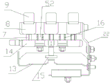
In order to achieve the purpose, the invention adopts the following technical scheme that the low-voltage distribution box comprises an outdoor box body, wherein a load switch is arranged in the outdoor box body, a wire outlet end of the load switch is respectively connected with a wire inlet end of a circuit breaker and a reactive compensation module through a bus, and a current transformer is sleeved on the bus; the reactive compensation module is characterized by comprising an upper mounting transverse plate and a lower mounting transverse plate, wherein one side of the upper mounting transverse plate is provided with a capacitor, and two sides of the lower mounting transverse plate are respectively provided with a capacitor; a composite switch mounting vertical plate is arranged in front of the capacitor, a branch incoming line breaker is arranged on the upper front portion of the composite switch mounting vertical plate, a composite switch is arranged on the lower front portion of the composite switch mounting vertical plate, a connecting transverse plate is arranged in the middle of the rear portion of the branch incoming line breaker, transverse strip-shaped holes are formed in portions of two sides of the connecting transverse plate, which are exposed out of two sides of the branch incoming line breaker, and mounting holes are formed in the composite switch mounting vertical plate corresponding to the;
the lower end of the vertical plate for installing the composite switch is bent forwards, mounting holes are formed in two ends of the bent part, and connecting holes are formed in the transverse plate corresponding to the mounting holes;
the lower end of the capacitor is provided with a capacitor mounting plate, the cross section of the capacitor mounting plate is shaped like a Chinese character 'ji', the bottom plates at two sides of the capacitor mounting plate are provided with connecting holes, and the mounting transverse plate is provided with mounting holes corresponding to the connecting holes;
connecting plates are arranged on two sides of the lower end of the capacitor, connecting holes are formed in the front and rear parts of the connecting plates, and mounting holes are formed in the transverse plate on the capacitor mounting plate corresponding to the connecting holes;
the four corners of the installation transverse plate are provided with upwards bent connecting pieces, the connecting pieces are provided with installation holes, a vertical support is arranged in the outdoor box body corresponding to the connecting pieces, and the vertical support is provided with a plurality of connecting holes corresponding to the installation holes from top to bottom;
the capacitor is connected with the outlet end of the branch inlet line breaker through the compound switch, the inlet end of the branch inlet line breaker is connected with the outlet end of the main inlet line breaker, and the inlet end of the main inlet line breaker is connected with the bus.
As a preferred scheme, the circuit breaker comprises a circuit breaker body, wherein a circuit breaker wrench 50 is arranged on the circuit breaker body, the upper end of the circuit breaker body is a circuit breaker wire inlet end, the lower end of the circuit breaker body is a circuit breaker wire outlet end 54, and a switching-off operation interlocking mechanism is arranged on the circuit breaker body;
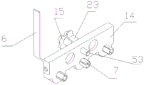
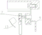
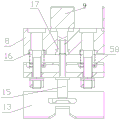
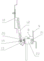
the opening operation interlocking mechanism comprises a breaker interlocking mounting plate 10, the breaker interlocking mounting plate 10 is connected with the front end face of a breaker body, a linkage part of a breaker wrench is arranged on the breaker interlocking mounting plate 10, a breaker interlocking baffle plate 11 is arranged on the outer side of the linkage part, the breaker interlocking baffle plate 11 is in shaft connection with the upper end of an interlocking connecting plate 12, the lower end of the interlocking connecting plate 12 is in shaft connection with the front part of one side of an operation handle baffle plate 13, the rear part of the side of the operation handle baffle plate 13 is in shaft connection with the front end of a connecting plate 22, the rear end of the connecting plate 22 is connected with a lower wire outlet base 8 through a fastener 21, an upper grounding base 14 is arranged in front of the lower wire outlet base 8; the middle part of the front end of the upper grounding seat 14 is provided with a grounding handle 15, and the lower wire outlet seat 8 is connected with a wire outlet end at the lower end of the breaker body through a lower wire outlet row 9.
As a preferable scheme, the upper end and the lower end of the composite switch 90 of the invention are provided with connecting holes, and the composite switch mounting vertical plate 89 is provided with mounting holes corresponding to the connecting holes.
As a preferred scheme, the load switch, the bus and the circuit breaker are arranged in the front area of the outdoor box body, the reactive compensation module is arranged in the rear area of the outdoor box body, the load switch is arranged below the left side, the bus comprises a left vertical bus, an upper horizontal bus and a right vertical bus, the lower end of the left vertical bus is connected with the outlet end of the load switch, the upper end of the left vertical bus is connected with the left end of the upper horizontal bus, the right end of the upper horizontal bus is connected with the upper end of the right vertical bus, and the lower end of the right vertical bus is connected with the inlet end of the circuit breaker.
As another preferred scheme, the cross section of the connecting transverse plate is in a shape of a Chinese character 'ji' with a forward vertical opening.
As another preferred scheme, the front end and the rear end of the installation transverse plate are bent downwards.
As another preferred scheme, a transverse insulator mounting beam is arranged at the rear end of the left vertical bus, two ends of the insulator mounting beam are connected with the mounting plate of the inner body of the outdoor box, and the front end of the insulator mounting beam is connected with the left vertical bus.
As another preferred scheme, a mounting plate is arranged between the upper ends of two vertical supports on the front side of the reactive compensation module, the mounting plate is a mounting plate which is convex backwards and is shaped like a Chinese character 'ji', mounting holes are arranged at two ends of the mounting plate corresponding to connecting holes of the vertical supports, a reactive compensation module main incoming line breaker and an arrester are transversely arranged at the front end of the mounting plate, and an outgoing line end of the reactive compensation module main incoming line breaker is connected with the arrester.
As another preferred scheme, the circuit breaker is arranged on a mounting plate, vertical plate-shaped connecting frames are arranged in outdoor boxes on two sides of the mounting plate, mounting holes are formed in two sides of the mounting plate, and a plurality of connecting holes are uniformly distributed in the vertical plate-shaped connecting frames from top to bottom corresponding to the mounting holes.
As another preferred scheme, the right vertical bus comprises an upper transverse plate bent forwards, the rear end of the upper transverse plate is connected with the upper end of a rear vertical plate, the lower end of the rear vertical plate is connected with the rear upper end of an inclined plate, the front lower end of the inclined plate is connected with the upper end of a front vertical plate, the lower end of the front vertical plate is connected with a wire inlet end of a circuit breaker through a fastener, and the front end of the upper transverse plate is connected with the upper horizontal bus through a fastener.
As another preferred scheme, the left vertical bus comprises a vertical plate, an upper transverse plate bent backwards is arranged at the upper end of the vertical plate, the rear end of the upper transverse plate is connected with the upper transverse bus through a fastener, the lower end of the vertical plate is connected with a wire outlet end of a load switch through a fastener, and a current transformer is arranged at the lower part of the vertical plate.
As another preferred scheme, the upper end of the outdoor box body is provided with a hanging frame.
As another preferred scheme, the hanging frame is a n-shaped frame, and two sides of the lower end of the n-shaped frame are connected with the upper end of the outdoor box body through fasteners.
As another preferred scheme, the number of the hanging frames is four, and the four hanging frames are respectively arranged at four corners of the upper end of the outdoor box body.
Secondly, air outlets are formed in the lower ends of the two sides of the outdoor box body.
In addition, a transverse grounding bar connecting plate is arranged at the lower end in the outdoor box body, and the front end of the grounding bar connecting plate is connected with a bottom plate of the outdoor box body through an L-shaped grounding bar connecting plate; the ground connection row connecting plate is arranged below the circuit breaker, and the ground copper braided wire 6 is connected with the ground connection row connecting plate.
The invention has the beneficial effects.
The low-voltage distribution box is convenient for mounting and arranging all parts of the reactive compensation module through mounting the transverse plate, the vertical plate, the connecting transverse plate and the capacitor mounting plate, and is reliable in connection.
Drawings
The invention is further described with reference to the following figures and detailed description. The scope of the invention is not limited to the following expressions.
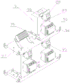
Fig. 1 is a schematic structural diagram of relevant components of the reactive compensation module of the low-voltage distribution box.
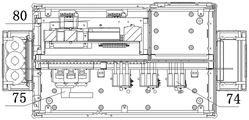
Fig. 2 is a front view of the low voltage distribution box of the present invention.
Fig. 3 is a top view of the low-voltage distribution box of the present invention.
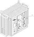
Fig. 4 is a perspective view of the low-voltage distribution box of the present invention.
Fig. 5 is another perspective view of the low voltage distribution box of the present invention.
Figure 6 is a rear view of the low-voltage distribution box of the present invention.
Fig. 7 is a schematic view of the connection of the combination switch of the low-voltage distribution box of the invention.
In fig. 1-7, 70 is a hanging frame, 71 is an insulator mounting beam, 72 is a ground bar connecting plate, 74 is a breaker, 75 is a load switch, 76 is a current transformer, 77 is a left vertical bus, 78 is an insulator mounting beam, 79 is an outdoor box, 80 is a reactive compensation module, 82 is a right vertical bus, 83 is an upper horizontal bus, 84 is an air outlet, 85 is an L-shaped ground bar connecting plate, 86 is a main incoming line breaker, 87 is a lightning arrester, 88 is a reactive compensation module branch incoming line breaker, 89 is a composite switch mounting vertical plate, 90 is a composite switch, 91 is a capacitor, 92 is a mounting plate, 93 is a connecting frame, 94 is a connecting piece, 95 is a capacitor mounting plate, 96 is a connecting plate, 97 is a mounting transverse plate, 98 is a transverse plate connecting hole, and 99 is a mounting hole.
Fig. 8 is a schematic structural diagram of the breaker in the open state.
Fig. 9 is a schematic structural diagram of a closing state of the circuit breaker according to the present invention.
Fig. 10 is a schematic structural diagram of the opening operation interlocking mechanism of the circuit breaker.
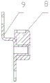
Fig. 11 is a schematic structural diagram of the relevant parts of the grounding seat 14 of the circuit breaker of the present invention.
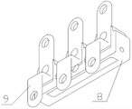
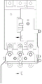
Fig. 12 is a schematic structural diagram of the lower outlet row 9 of the circuit breaker of the present invention.
Fig. 13 is a schematic structural diagram of relevant components of the lower outlet base 8 of the circuit breaker.
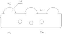
Figure 14 is a front view of the upper ground socket 14 of the circuit breaker of the present invention.
Fig. 15 is a cross-sectional view C-C of fig. 14.
FIG. 16 is a cross-sectional view taken along line E-E of FIG. 14
Fig. 17 is a front view of the circuit breaker in a closed state.
Fig. 18 is a cross-sectional view C-C of fig. 17.
Fig. 19 is a front view showing the opening state of the circuit breaker according to the present invention.
Fig. 20 is a cross-sectional view C-C of fig. 19 of the present invention.
Fig. 21 is a rear view of the lower outlet base 8 of the circuit breaker of the present invention.
Fig. 22 is a cross-sectional view C-C of fig. 21.
Fig. 23 is a cross-sectional view taken along line D-D of fig. 21.
Fig. 24 is a front view of the breaker opening operation interlocking mechanism of the invention.
Fig. 25 is a cross-sectional view C-C of fig. 24.
Fig. 26 is a sectional view F-F of fig. 24.
Fig. 27 is a top view of the circuit breaker opening operation interlock mechanism of the present invention.
Fig. 28 is a side view of the circuit breaker opening operation interlocking mechanism of the present invention.
Fig. 29 is a schematic structural view of a related part of the circuit breaker interlocking part of the invention.
Fig. 30 is a schematic structural view of a circuit breaker linkage assembly of the present invention.
Fig. 31 is a front view of the outdoor integrated low voltage distribution box of the present invention.
Fig. 32 is a top view of the outdoor integrated low voltage distribution box of the present invention.
Fig. 33 is a perspective view of the interior structure of the outdoor integrated low voltage distribution box of the present invention.
Fig. 34 is a perspective view of the outdoor integrated low voltage distribution box of the present invention.
Fig. 35 is a circuit diagram of the outdoor integrated low-voltage distribution box of the invention.
Fig. 36 is a schematic structural diagram of relevant components of the reactive compensation module of the outdoor comprehensive low-voltage distribution box.
In fig. 31-36, 70 is a hanging frame, 71 is an insulator mounting beam, 72 is a ground bar connecting plate, 74 is a breaker, 75 is a load switch, 76 is a current transformer, 77 is a left vertical bus, 78 is an insulator mounting beam, 79 is an outdoor box, 80 is a reactive compensation module, 82 is a right vertical bus, 83 is an upper horizontal bus, 84 is an air outlet, 85 is an L-shaped ground bar connecting plate, 86 is a mounting plate, 87 is a lightning arrester, 88 is a reactive compensation module incoming line breaker, 89 is a vertical bracket, 90 is a connecting piece, and 91 is a mounting plate.
Detailed Description
As shown in the figure, the low-voltage distribution box comprises an outdoor box body, wherein a load switch is arranged in the outdoor box body, a wire outlet end of the load switch is respectively connected with a wire inlet end and a reactive compensation module of a circuit breaker through a bus, and a current transformer is sleeved on the bus; the reactive compensation module is characterized by comprising an upper mounting transverse plate and a lower mounting transverse plate, wherein one side of the upper mounting transverse plate is provided with a capacitor, and two sides of the lower mounting transverse plate are respectively provided with a capacitor; a composite switch mounting vertical plate is arranged in front of the capacitor, a branch incoming line breaker is arranged on the upper front portion of the composite switch mounting vertical plate, a composite switch 90 is arranged on the lower front portion of the composite switch mounting vertical plate, a connecting transverse plate is arranged in the middle of the rear portion of the branch incoming line breaker, transverse strip-shaped holes are formed in portions of two sides of the connecting transverse plate, which are exposed out of two sides of the branch incoming line breaker, and mounting holes are formed in the composite switch mounting vertical plate corresponding to the;
the lower end of the vertical plate for installing the composite switch is bent forwards, mounting holes are formed in two ends of the bent part, and connecting holes are formed in the transverse plate corresponding to the mounting holes;
the lower end of the capacitor is provided with a capacitor mounting plate, the cross section of the capacitor mounting plate is shaped like a Chinese character 'ji', the bottom plates at two sides of the capacitor mounting plate are provided with connecting holes, and the mounting transverse plate is provided with mounting holes corresponding to the connecting holes;
connecting plates are arranged on two sides of the lower end of the capacitor, connecting holes are formed in the front and rear parts of the connecting plates, and mounting holes are formed in the transverse plate on the capacitor mounting plate corresponding to the connecting holes;
the four corners of the installation transverse plate are provided with upwards bent connecting pieces, the connecting pieces are provided with installation holes, a vertical support is arranged in the outdoor box body corresponding to the connecting pieces, and the vertical support is provided with a plurality of connecting holes corresponding to the installation holes from top to bottom;
the capacitor is connected with the outlet end of the branch inlet line breaker through the compound switch, the inlet end of the branch inlet line breaker is connected with the outlet end of the main inlet line breaker, and the inlet end of the main inlet line breaker is connected with the bus.
The upper end and the lower end of the combination switch 90 are provided with connecting holes, and the combination switch mounting vertical plate 89 is provided with mounting holes 99 corresponding to the connecting holes. The combination switch is fixed on the combination switch mounting vertical plate 89 through the fastener, the connecting hole and the mounting hole.
The breaker comprises a breaker body, a breaker wrench 50 is arranged on the breaker body, the upper end of the breaker body is a breaker inlet end, the lower end of the breaker body is a breaker outlet end 54, and a tripping operation interlocking mechanism is arranged on the breaker body;
the opening operation interlocking mechanism comprises a breaker interlocking mounting plate 10, the breaker interlocking mounting plate 10 is connected with the front end face of a breaker body, a linkage part of a breaker wrench is arranged on the breaker interlocking mounting plate 10, a breaker interlocking baffle plate 11 is arranged on the outer side of the linkage part, the breaker interlocking baffle plate 11 is in shaft connection with the upper end of an interlocking connecting plate 12, the lower end of the interlocking connecting plate 12 is in shaft connection with the front part of one side of an operation handle baffle plate 13, the rear part of the side of the operation handle baffle plate 13 is in shaft connection with the front end of a connecting plate 22, the rear end of the connecting plate 22 is connected with a lower wire outlet base 8 through a fastener 21, an upper grounding base 14 is arranged in front of the lower wire outlet base 8; the middle part of the front end of the upper grounding seat 14 is provided with a grounding handle 15, and the lower wire outlet seat 8 is connected with a wire outlet end at the lower end of the breaker body through a lower wire outlet row 9.
The circuit breaker is provided with the wire outlet seat, the grounding seat and the grounding copper braided wire, and has a discharging function. Therefore, the potential safety hazard of incomplete opening caused by internal faults of the circuit breaker can be eliminated.
The invention only needs to move the wrench from the closing position to the opening position, and then the breaker interlocking mechanism is opened, so that an operator can rotate clockwise at the opening position through the operating handle to drive the grounding column to be connected with the outgoing cable and to be connected with the grounding in the outdoor box body through the grounding copper braided wire, thereby avoiding the reverse power transmission of the outgoing cable and improving the safety of the device.
The invention further improves the operation safety of the device by opening the brake to operate the interlocking mechanism.
Load switch, generating line and circuit breaker set up in outdoor box front portion region, and reactive compensation module sets up in the rear portion region of outdoor box, and load switch sets up in the left side below, and the generating line includes that left side erects generating line, last generating line and right side and erects the generating line, and left side erects the generating line lower extreme and links to each other with the load switch terminal outgoing lines, and left side erects the generating line upper end and goes up the generating line left end and links to each other, goes up the generating line right-hand member and erects the generating line upper end with the right side and link to each. The outdoor distribution box is provided with the left vertical bus, the upper horizontal bus and the right vertical bus, so that the components can be conveniently connected, and the connection is reliable.
The cross section of the connecting transverse plate 98 is shaped like a Chinese character 'ji' with a vertical opening facing forward.
The front and rear ends of the mounting transverse plate 97 are bent downwards; the structural strength is high.
The rear end of the left vertical bus is provided with a transverse insulator mounting beam, two ends of the insulator mounting beam are connected with the outdoor box inner body mounting plate, and the front end of the insulator mounting beam is connected with the left vertical bus.
The mounting panel is provided with between two perpendicular support upper ends of reactive compensation module front side, and the mounting panel is the nearly font mounting panel of backward protrusion, and the mounting panel both ends are provided with the mounting hole corresponding to the connecting hole of erecting the support, and the mounting panel front end is along transversely being provided with reactive compensation module total inlet wire circuit breaker and arrester, and reactive compensation module total inlet wire circuit breaker's leading-out terminal links to each other with the arrester.
The circuit breaker sets up on the mounting panel, is provided with the vertical plate-like link in the outdoor box of mounting panel both sides, and the mounting panel both sides are provided with the mounting hole, and a plurality of connecting holes of equipartition from top to bottom are corresponding to the mounting hole on the vertical plate-like link.
The right vertical bus comprises an upper transverse plate bent forwards, the rear end of the upper transverse plate is connected with the upper end of a rear vertical plate, the lower end of the rear vertical plate is connected with the upper end of the inclined plate, the front lower end of the inclined plate is connected with the upper end of a front vertical plate, the lower end of the front vertical plate is connected with the wire inlet end of the circuit breaker through a fastener, and the front end of the upper transverse plate is connected with the upper vertical bus through a fastener.
The left vertical bus comprises a vertical plate, the upper end of the vertical plate is an upper transverse plate bent backwards, the rear end of the upper transverse plate is connected with the upper horizontal bus through a fastener, the lower end of the vertical plate is connected with a wire outlet end of the load switch through a fastener, and the current transformer is arranged on the lower portion of the vertical plate.
And a hanging frame is arranged at the upper end of the outdoor box body.
The hanging frame is a n-shaped frame, and two sides of the lower end of the n-shaped frame are connected with the upper end of the outdoor box body through fasteners.
The number of the hanging frames is four, and the four hanging frames are respectively arranged at four corners of the upper end of the outdoor box body.
The outdoor box both sides lower extreme is provided with the air exit.
A transverse grounding bar connecting plate is arranged at the lower end in the outdoor box body, and the front end of the grounding bar connecting plate is connected with an outdoor box body bottom plate through an L-shaped grounding bar connecting plate; the ground connection row connecting plate is arranged below the circuit breaker, and the ground copper braided wire 6 is connected with the ground connection row connecting plate.
The linkage component comprises a vertical square plate 61, a clamping plate 60 extending towards the side is arranged on the inner side of the vertical square plate, and the circuit breaker wrench 50 is arranged in a notch of the clamping plate; vertical strip-shaped openings 62 are formed in the vertical square plates, transverse guide pillars 63 on the breaker interlocking mounting plate 10 penetrate through the vertical strip-shaped openings, and the vertical square plates are arranged between the breaker interlocking mounting plate 10 and the breaker body.
The breaker interlocking mounting plate 10 is a vertical rectangular plate, the upper end and the lower end of the rectangular plate are bent towards the side of the breaker body, the upper end is bent to be close to the inner side and is provided with an upper connecting part extending upwards, the lower end is bent to be close to the inner side and is provided with a lower connecting part extending downwards, the upper connecting part is connected with the upper end of the breaker body through a fastener, and the lower connecting part is connected with the lower end of the breaker body through a fastener; the middle part of the inner side end of the rectangular plate is provided with a horn-shaped notch.
The upper grounding seat 14 is provided with a grounding column 7, the grounding column 7 is poured in the upper grounding seat 14, and the upper grounding seat 14 is an insulating part; the insulating strength is good, and the safety is high.
The entrance notch of the breaker closing limit baffle 23 is a horn-shaped opening.
The upper grounding seat 14 comprises a transverse long plate-shaped shell, the outer side wall of the long plate-shaped shell is fixed with the upper end of the grounding copper braided wire 6 through an inner hexagon bolt, the upper end of the long plate-shaped shell is provided with a semicircular bulge protruding upwards, and the center of the lower end of the semicircular bulge is provided with a mounting hole of the grounding column 7.
The semicircular bulges are three and evenly distributed along the length direction of the long plate-shaped shell, pressing guide pillar mounting holes are formed in the long plate-shaped shell on two sides below the middle semicircular bulge, and mounting holes for grounding handles 15 are formed in the long plate-shaped shell on the lower portion between the pressing guide pillar mounting holes on two sides.
The rear end of the lower wire outlet seat 8 is provided with a lower wire outlet row 9, the lower wire outlet seat 8 comprises a transverse long plate-shaped shell, the upper end of the long plate-shaped shell is provided with a semicircular bulge protruding upwards, and the center of the lower end of the semicircular bulge is a mounting hole for the lower wire outlet row 9.
The outlet line row 9 comprises a vertical Z-shaped connecting sheet, the lower end of the front upper part of the Z-shaped connecting sheet is provided with a cylindrical slot extending towards the upper grounding seat 14 side, the cylindrical slot is inserted into the mounting hole of the lower outlet line row 9, the front upper part of the Z-shaped connecting sheet is arranged at the rear end of the lower outlet line seat 8, and the upper end and the lower end of the Z-shaped connecting sheet are provided with connecting holes; the connecting hole at the upper end of the Z-shaped connecting sheet is connected with the line outlet end of the circuit breaker through a fastener, and the connecting hole at the lower end of the Z-shaped connecting sheet is a connecting hole of a line outlet cable of the circuit breaker.
The semicircular bulges on the lower wire outlet seat 8 are three and evenly distributed along the length direction of the long plate-shaped shell.
The cylindrical slot of the lower outlet row 9 is poured into the mounting hole of the lower outlet row 9 of the lower outlet base 8; the insulating strength is good, and the safety is high.
The front end of the grounding handle 15 penetrates through a mounting hole of the grounding handle 15 on the grounding seat 14 and is screwed into a threaded hole of a threaded insert 17 on the lower wire outlet seat 8, the front end of the compression guide post is inserted into a guide hole on the lower wire outlet seat 8, the rear part of the compression guide post is a stud, the rear end of the stud is screwed through a mounting threaded hole of the compression guide post on the grounding seat 14 and is screwed with a nut, and an elastic pad and a flat pad are arranged between the nut and the front end face of the grounding seat 14.
The butt joint face of the grounding seat 14 and the outgoing line seat 8 is correspondingly provided with an outward-expanding groove, a pressing spring is sleeved on the pressing guide post between the two outward-expanding grooves, one end of the pressing spring is connected with the bottom face of the outward-expanding groove of the grounding seat 14, and the other end of the pressing spring is connected with the bottom face of the outward-expanding groove of the outgoing line seat 8.
The compression spring can enable the grounding post 7 to be better connected with the lower wire outlet row 9, and the contact pressure of the grounding post is increased. When the grounding handle 15 is rotated to be grounded, the grounding column 7 is better connected with the lower wire outlet row 9; when the grounding handle 15 rotates from the grounding position to the shunting position, the compression spring is restored to the original state by compression.
The threaded insert 17 is cast into the lower outlet socket 8.
The operation of the circuit breaker of the present invention will be described with reference to the accompanying drawings.
As shown in fig. 9, when the circuit breaker is in the closing position, the circuit breaker wrench is lifted, the linkage component drives the circuit breaker linkage baffle 11 to move upwards, and finally the operation handle 13 is driven to lift up to block the grounding handle 15, so that the grounding handle cannot rotate, the grounding column 7 cannot be connected with the lower outlet row 9, and the grounding operation cannot be completed.
When the breaker is in the separating brake, the circuit breaker spanner is dialled down, linkage part drive circuit breaker interlocking baffle 11 moves down, finally drive operating handle 13 and fall down, operating handle 13 can not block ground connection handle 15, operating personnel can rotate ground connection handle 15 (operating handle 13 middle part notch is wide enough, 23 outer ends of circuit breaker combined floodgate limit baffle can change over), the position of ground connection handle 15 front end screw rod 53 in the 8 screw holes of base of being qualified for the next round of competitions down moves forward to drive ground connection post 7 and insert the cylindric slot on the base of being qualified for the next round of competitions 9 down, accomplish the ground connection of circuit breaker leading-out terminal.
As shown in fig. 8, when the circuit breaker is at the ground position (after the ground handle 15 rotates clockwise for one or more weeks, the outer end of the circuit breaker closing limit baffle 23 enters the notch in the middle of the operating handle baffle 13), the lower end of the circuit breaker closing limit baffle 23 is lower than the lower end of the operating handle baffle 13, the operating handle baffle 13 cannot rotate upwards, and the interlocking connection plate 12 cannot move upwards, so that the circuit breaker cannot be closed.
When the circuit breaker moves to the isolation position from the grounding position, namely the grounding handle 15 rotates anticlockwise to separate the grounding column 7 from the lower outlet row 9, meanwhile, the outer end of the circuit breaker closing limiting baffle 23 does not enter a notch in the middle of the operating handle baffle 13, the operating handle baffle 13 can rotate outwards and upwards, and the circuit breaker can be closed.
Through the above operation, when the circuit breaker is in the on-position, the grounding column 7 cannot be connected with the lower outlet row 9, and a grounding loop cannot be formed, so that a loaded grounding switch is prevented from being turned on; the safety of the device is improved. When the circuit breaker is in the opening position, the grounding column 7 can be connected with the lower outlet row 9 to form a grounding loop.
The circuit breaker can be applied to an outdoor comprehensive low-voltage distribution box, the outdoor comprehensive low-voltage distribution box comprises an outdoor box body, a load switch is arranged in the outdoor box body, a wire outlet end of the load switch is respectively connected with a wire inlet end and a reactive compensation module of the circuit breaker through a bus, and a current transformer is sleeved on the bus;
the load switch, the bus and the breaker are arranged in the front area of the outdoor box body, the reactive compensation module is arranged in the rear area of the outdoor box body, the load switch is arranged below the left side, the bus comprises a left vertical bus, an upper horizontal bus and a right vertical bus, the lower end of the left vertical bus is connected with a wire outlet end of the load switch, the upper end of the left vertical bus is connected with the left end of the upper horizontal bus, the right end of the upper horizontal bus is connected with the upper end of the right vertical bus, and the lower end of the right vertical bus is connected with a wire inlet end;
the breaker comprises a breaker body, a breaker wrench 50 is arranged on the breaker body, the upper end of the breaker body is a breaker inlet end, the lower end of the breaker body is a breaker outlet end 54, and a tripping operation interlocking mechanism is arranged on the breaker body;
the opening operation interlocking mechanism comprises a breaker interlocking mounting plate 10, the breaker interlocking mounting plate 10 is connected with the front end face of a breaker body, a linkage part of a breaker wrench is arranged on the breaker interlocking mounting plate 10, a breaker interlocking baffle plate 11 is arranged on the outer side of the linkage part, the breaker interlocking baffle plate 11 is in shaft connection with the upper end of an interlocking connecting plate 12, the lower end of the interlocking connecting plate 12 is in shaft connection with the front part of one side of an operation handle baffle plate 13, the rear part of the side of the operation handle baffle plate 13 is in shaft connection with the front end of a connecting plate 22, the rear end of the connecting plate 22 is connected with a lower wire outlet base 8 through a fastener 21, an upper grounding base 14 is arranged in front of the lower wire outlet base 8; the middle part of the front end of the upper grounding seat 14 is provided with a grounding handle 15, and the lower wire outlet seat 8 is connected with a wire outlet end at the lower end of the breaker body through a lower wire outlet row 9.
The outdoor comprehensive low-voltage distribution box is provided with the left vertical bus, the upper transverse bus and the right vertical bus, so that the components can be conveniently connected, and the connection is reliable.
The outdoor comprehensive low-voltage distribution box circuit breaker is provided with the wire outlet seat, the grounding seat and the grounding copper braided wire and has a discharging function. Therefore, the potential safety hazard of incomplete opening caused by internal faults of the circuit breaker can be eliminated.
The outdoor comprehensive low-voltage distribution box is maintained only by moving the wrench downwards from the switching-on position to the switching-off position, and then the breaker linkage mechanism is opened, so that an operator can rotate clockwise at the switching-off position through the operating handle to drive the grounding column to be connected with the outgoing cable and to be connected with the grounding in the outdoor box body through the grounding copper braided wire, and therefore reverse power transmission of the outgoing cable is avoided, and safety of the device is improved.
The outdoor comprehensive low-voltage distribution box further improves the operation safety of the device by opening the brake operation interlocking mechanism.
The rear end of the left vertical bus is provided with a transverse insulator mounting beam, two ends of the insulator mounting beam are connected with the outdoor box inner body mounting plate, and the front end of the insulator mounting beam is connected with the left vertical bus.
And the reactive compensation module adopts a Static Var Generator (SVG).
The reactive compensation module lower extreme passes through the fastener setting on the mounting panel, and the mounting panel four corners is provided with the connecting piece of upwards buckling, is provided with the mounting hole on the connecting piece, is provided with perpendicular support corresponding to the connecting piece in the outdoor box, erects and is provided with a plurality of connecting holes corresponding to the mounting hole from top to bottom on the support.
The utility model discloses a reactive compensation module, including reactive compensation module inlet wire circuit breaker, mounting panel both ends are provided with the mounting hole corresponding to the connecting hole of erecting the support, the mounting panel front end is along transversely being provided with reactive compensation module inlet wire circuit breaker and arrester, the inlet wire end of reactive compensation module inlet wire circuit breaker links to each other with the generating line, the outlet terminal of reactive compensation module inlet wire circuit breaker links to each other with the wiring end and the arrester of reactive compensation module respectively.
The circuit breaker sets up on the mounting panel, is provided with the vertical plate-like link in the outdoor box of mounting panel both sides, and the mounting panel both sides are provided with the mounting hole, and a plurality of connecting holes of equipartition from top to bottom are corresponding to the mounting hole on the vertical plate-like link.
The right vertical bus comprises an upper transverse plate bent forwards, the rear end of the upper transverse plate is connected with the upper end of a rear vertical plate, the lower end of the rear vertical plate is connected with the upper end of the inclined plate, the front lower end of the inclined plate is connected with the upper end of a front vertical plate, the lower end of the front vertical plate is connected with the wire inlet end of the circuit breaker through a fastener, and the front end of the upper transverse plate is connected with the upper vertical bus through a fastener.
The left vertical bus comprises a vertical plate, the upper end of the vertical plate is an upper transverse plate bent backwards, the rear end of the upper transverse plate is connected with the upper horizontal bus through a fastener, the lower end of the vertical plate is connected with a wire outlet end of the load switch through a fastener, and the current transformer is arranged on the lower portion of the vertical plate.
And a hanging frame is arranged at the upper end of the outdoor box body.
The hanging frame is a n-shaped frame, and two sides of the lower end of the n-shaped frame are connected with the upper end of the outdoor box body through fasteners.
The number of the hanging frames is four, and the four hanging frames are respectively arranged at four corners of the upper end of the outdoor box body.
The outdoor box both sides lower extreme is provided with the air exit.
A transverse grounding bar connecting plate is arranged at the lower end in the outdoor box body, and the front end of the grounding bar connecting plate is connected with an outdoor box body bottom plate through an L-shaped grounding bar connecting plate; the ground connection row connecting plate is arranged below the circuit breaker, and the ground copper braided wire 6 is connected with the ground connection row connecting plate.
An exhaust fan can be arranged to dissipate heat of the SVG.
It should be understood that the detailed description of the present invention is only for illustrating the present invention and is not limited by the technical solutions described in the embodiments of the present invention, and those skilled in the art should understand that the present invention can be modified or substituted equally to achieve the same technical effects; as long as the use requirements are met, the method is within the protection scope of the invention.
Claims (10)
1. A low-voltage distribution box comprises an outdoor box body, wherein a load switch is arranged in the outdoor box body, a wire outlet end of the load switch is respectively connected with a wire inlet end and a reactive compensation module of a circuit breaker through a bus, and a current transformer is sleeved on the bus; the reactive compensation module is characterized by comprising an upper mounting transverse plate and a lower mounting transverse plate, wherein one side of the upper mounting transverse plate is provided with a capacitor, and two sides of the lower mounting transverse plate are respectively provided with a capacitor; a composite switch mounting vertical plate is arranged in front of the capacitor, a branch incoming line breaker is arranged on the upper front portion of the composite switch mounting vertical plate, a composite switch is arranged on the lower front portion of the composite switch mounting vertical plate, a connecting transverse plate is arranged in the middle of the rear portion of the branch incoming line breaker, transverse strip-shaped holes are formed in portions of two sides of the connecting transverse plate, which are exposed out of two sides of the branch incoming line breaker, and mounting holes are formed in the composite switch mounting vertical plate corresponding to the;
the lower end of the vertical plate for installing the composite switch is bent forwards, mounting holes are formed in two ends of the bent part, and connecting holes are formed in the transverse plate corresponding to the mounting holes;
the lower end of the capacitor is provided with a capacitor mounting plate, the cross section of the capacitor mounting plate is shaped like a Chinese character 'ji', the bottom plates at two sides of the capacitor mounting plate are provided with connecting holes, and the mounting transverse plate is provided with mounting holes corresponding to the connecting holes;
connecting plates are arranged on two sides of the lower end of the capacitor, connecting holes are formed in the front and rear parts of the connecting plates, and mounting holes are formed in the transverse plate on the capacitor mounting plate corresponding to the connecting holes;
the four corners of the installation transverse plate are provided with upwards bent connecting pieces, the connecting pieces are provided with installation holes, a vertical support is arranged in the outdoor box body corresponding to the connecting pieces, and the vertical support is provided with a plurality of connecting holes corresponding to the installation holes from top to bottom;
the capacitor is connected with the outlet end of the branch inlet line breaker through the compound switch, the inlet end of the branch inlet line breaker is connected with the outlet end of the main inlet line breaker, and the inlet end of the main inlet line breaker is connected with the bus.
2. The low-voltage distribution box according to claim 1, wherein the breaker comprises a breaker body, a breaker wrench (50) is arranged on the breaker body, the upper end of the breaker body is a breaker inlet end, the lower end of the breaker body is a breaker outlet end (54), and a tripping operation interlocking mechanism is arranged on the breaker body;
the opening operation interlocking mechanism comprises a breaker interlocking mounting plate (10), the breaker interlocking mounting plate (10) is connected with the front end face of a breaker body, a linkage part of a breaker wrench is arranged on the breaker interlocking mounting plate (10), a breaker interlocking baffle (11) is arranged on the outer side of the linkage part, the breaker interlocking baffle (11) is in shaft connection with the upper end of an interlocking connecting plate (12), the lower end of the interlocking connecting plate (12) is in shaft connection with the front part of one side of an operating handle baffle (13), the rear part of the side of the operating handle baffle (13) is in shaft connection with the front end of a connecting plate (22), the rear end of the connecting plate (22) is connected with a lower wire outlet seat (8) through a fastener (21), an upper grounding seat (14) is arranged in front of the lower wire outlet seat (8), and a copper braided wire (6) is arranged on the; the middle part of the front end of the upper grounding seat (14) is provided with a grounding handle (15), and the lower wire outlet seat (8) is connected with a wire outlet end at the lower end of the breaker body through a lower wire outlet row (9).
3. Low-voltage distribution box according to claim 1, characterized in that said composite switch (90) is provided, at the upper and lower ends, with connection holes, and in that the composite switch mounting risers (89) are provided with mounting holes corresponding to the connection holes.
4. The low-voltage distribution box according to claim 1, wherein the load switch, the bus and the breaker are arranged in a front region of the outdoor box, the reactive compensation module is arranged in a rear region of the outdoor box, the load switch is arranged below the left side, the bus comprises a left vertical bus, an upper horizontal bus and a right vertical bus, the lower end of the left vertical bus is connected with a wire outlet end of the load switch, the upper end of the left vertical bus is connected with the left end of the upper horizontal bus, the right end of the upper horizontal bus is connected with the upper end of the right vertical bus, and the lower end of the right vertical bus is connected with a wire inlet end of the breaker.
5. The low-voltage distribution box according to claim 1, wherein a transverse insulator mounting beam is arranged at the rear end of the left vertical bus, two ends of the insulator mounting beam are connected with the mounting plate of the outdoor box body, and the front end of the insulator mounting beam is connected with the left vertical bus.
6. The low-voltage distribution box according to claim 5, wherein a mounting plate is arranged between the upper ends of the two vertical supports at the front side of the reactive compensation module, the mounting plate is a backward-convex mounting plate in a shape like a Chinese character ji, mounting holes are arranged at the two ends of the mounting plate corresponding to the connecting holes of the vertical supports, a reactive compensation module main incoming line breaker and an arrester are transversely arranged at the front end of the mounting plate, and the outlet end of the reactive compensation module main incoming line breaker is connected with the arrester.
7. The low-voltage distribution box of claim 1, wherein the circuit breaker is disposed on a mounting plate, vertical plate-shaped connecting frames are disposed in the outdoor box on two sides of the mounting plate, mounting holes are disposed on two sides of the mounting plate, and a plurality of connecting holes are uniformly distributed on the vertical plate-shaped connecting frames from top to bottom corresponding to the mounting holes.
8. The low-voltage distribution box according to claim 4, wherein the right vertical bus comprises an upper transverse plate bent forward, the rear end of the upper transverse plate is connected with the upper end of a rear vertical plate, the lower end of the rear vertical plate is connected with the rear upper end of an inclined plate, the front lower end of the inclined plate is connected with the upper end of a front vertical plate, the lower end of the front vertical plate is connected with the wire inlet end of the circuit breaker through a fastener, and the front end of the upper transverse plate is connected with the upper horizontal bus through a fastener.
9. The low-voltage distribution box according to claim 4, wherein the left vertical bus comprises a vertical plate, the upper end of the vertical plate is an upper horizontal plate bent backwards, the rear end of the upper horizontal plate is connected with the upper horizontal bus through a fastener, the lower end of the vertical plate is connected with the wire outlet end of the load switch through a fastener, and the current transformer is arranged on the lower portion of the vertical plate.
10. The low-voltage distribution box according to claim 1, wherein a transverse grounding bar connecting plate is arranged at the inner lower end of the outdoor box body, and the front end of the grounding bar connecting plate is connected with the bottom plate of the outdoor box body through an L-shaped grounding bar connecting plate; the grounding bar connecting plate is arranged below the circuit breaker, and the grounding copper braided wire (6) is connected with the grounding bar connecting plate.
Priority Applications (1)
| Application Number | Priority Date | Filing Date | Title |
|---|---|---|---|
| CN201910856700.3A CN110768136B (en) | 2019-09-11 | 2019-09-11 | Low-voltage distribution box |
Applications Claiming Priority (1)
| Application Number | Priority Date | Filing Date | Title |
|---|---|---|---|
| CN201910856700.3A CN110768136B (en) | 2019-09-11 | 2019-09-11 | Low-voltage distribution box |
Publications (2)
| Publication Number | Publication Date |
|---|---|
| CN110768136A true CN110768136A (en) | 2020-02-07 |
| CN110768136B CN110768136B (en) | 2020-11-06 |
Family
ID=69329394
Family Applications (1)
| Application Number | Title | Priority Date | Filing Date |
|---|---|---|---|
| CN201910856700.3A Active CN110768136B (en) | 2019-09-11 | 2019-09-11 | Low-voltage distribution box |
Country Status (1)
| Country | Link |
|---|---|
| CN (1) | CN110768136B (en) |
Cited By (1)
| Publication number | Priority date | Publication date | Assignee | Title |
|---|---|---|---|---|
| CN112165006A (en) * | 2020-11-11 | 2021-01-01 | 国网辽宁省电力有限公司本溪供电公司 | Outdoor low-voltage distribution box lock operating mechanism |
Citations (5)
| Publication number | Priority date | Publication date | Assignee | Title |
|---|---|---|---|---|
| CN2746501Y (en) * | 2004-10-30 | 2005-12-14 | 汕头正超电气有限公司 | Mechanical locking operation mechanism for electric switch cabinet |
| CN201315261Y (en) * | 2008-11-27 | 2009-09-23 | 常州市明及电气技术开发有限公司 | Isolation switch and cabinet door interlocking mechanism |
| CN205159150U (en) * | 2015-10-20 | 2016-04-13 | 珠海沃顿电气有限公司 | Maloperation interlock is prevented to circuit breaker |
| CN110071453A (en) * | 2019-05-24 | 2019-07-30 | 辽宁电能发展股份有限公司 | A kind of distributed board outdoor |
| CN110224328A (en) * | 2019-05-13 | 2019-09-10 | 浙江途远电气有限公司 | A kind of combined electrical apparatus |
-
2019
- 2019-09-11 CN CN201910856700.3A patent/CN110768136B/en active Active
Patent Citations (5)
| Publication number | Priority date | Publication date | Assignee | Title |
|---|---|---|---|---|
| CN2746501Y (en) * | 2004-10-30 | 2005-12-14 | 汕头正超电气有限公司 | Mechanical locking operation mechanism for electric switch cabinet |
| CN201315261Y (en) * | 2008-11-27 | 2009-09-23 | 常州市明及电气技术开发有限公司 | Isolation switch and cabinet door interlocking mechanism |
| CN205159150U (en) * | 2015-10-20 | 2016-04-13 | 珠海沃顿电气有限公司 | Maloperation interlock is prevented to circuit breaker |
| CN110224328A (en) * | 2019-05-13 | 2019-09-10 | 浙江途远电气有限公司 | A kind of combined electrical apparatus |
| CN110071453A (en) * | 2019-05-24 | 2019-07-30 | 辽宁电能发展股份有限公司 | A kind of distributed board outdoor |
Non-Patent Citations (1)
| Title |
|---|
| 李春和: "《防止电气误操作技术及事故分析》", 30 April 2010, 中国电力出版社 * |
Cited By (2)
| Publication number | Priority date | Publication date | Assignee | Title |
|---|---|---|---|---|
| CN112165006A (en) * | 2020-11-11 | 2021-01-01 | 国网辽宁省电力有限公司本溪供电公司 | Outdoor low-voltage distribution box lock operating mechanism |
| CN112165006B (en) * | 2020-11-11 | 2022-08-30 | 国网辽宁省电力有限公司本溪供电公司 | Outdoor low-voltage distribution box lock operating mechanism |
Also Published As
| Publication number | Publication date |
|---|---|
| CN110768136B (en) | 2020-11-06 |
Similar Documents
| Publication | Publication Date | Title |
|---|---|---|
| CN110768127B (en) | Outdoor comprehensive low-voltage distribution box | |
| CN110768136B (en) | Low-voltage distribution box | |
| CN210350382U (en) | Drawer type outlet cabinet | |
| CN201774141U (en) | Combined high-tension switch cabinet | |
| CN110767509B (en) | Low-voltage circuit breaker | |
| KR100615721B1 (en) | Receiving board for very high voltage | |
| CN209805230U (en) | Low-voltage draw-out type circuit breaker | |
| US3804998A (en) | Draw out circuit breaker with improved draw-in bolt contact mounting means | |
| CN206532907U (en) | Rectangular bus bar ground wire link | |
| CN210200619U (en) | Hard isolation baffle for replacing isolation switch insulation combination in electrified manner | |
| CN213583674U (en) | Circuit breaker | |
| CN201466494U (en) | Low voltage power distribution set switching device | |
| CN205104454U (en) | Switching device before plug -in table | |
| KR100665044B1 (en) | Distributing board for low voltage | |
| CN216749706U (en) | Isolating switch | |
| CN2686172Y (en) | Box type gas isolation metal closed switch equipment | |
| CN202134809U (en) | Novel high tension switchgear | |
| CN218070731U (en) | Easily install assembled high-voltage board | |
| CN218161476U (en) | 12kV environment-friendly gas insulation ring main unit | |
| CN210607021U (en) | Fuse chamber door interlocking device applied to combined electrical appliance cabinet | |
| CN208589680U (en) | A kind of Novel distribution box | |
| CN219477368U (en) | Cable trench distribution box | |
| CN203589566U (en) | Standard MNS low voltage withdrawable switch cabinet body of half function board | |
| CN210327362U (en) | Variable frequency control cabinet for rail transit | |
| CN219696932U (en) | Bus bridge device and prefabricated cabin |
Legal Events
| Date | Code | Title | Description |
|---|---|---|---|
| PB01 | Publication | ||
| PB01 | Publication | ||
| SE01 | Entry into force of request for substantive examination | ||
| SE01 | Entry into force of request for substantive examination | ||
| GR01 | Patent grant | ||
| GR01 | Patent grant |