CN110762004A - Asymmetric elliptic twisted-blade roots rotor, compressor and expander - Google Patents
Asymmetric elliptic twisted-blade roots rotor, compressor and expander Download PDFInfo
- Publication number
- CN110762004A CN110762004A CN201911061041.0A CN201911061041A CN110762004A CN 110762004 A CN110762004 A CN 110762004A CN 201911061041 A CN201911061041 A CN 201911061041A CN 110762004 A CN110762004 A CN 110762004A
- Authority
- CN
- China
- Prior art keywords
- parameter
- elliptical
- rotor
- asymmetric
- equation
- Prior art date
- Legal status (The legal status is an assumption and is not a legal conclusion. Google has not performed a legal analysis and makes no representation as to the accuracy of the status listed.)
- Granted
Links
Images


Classifications
-
- F—MECHANICAL ENGINEERING; LIGHTING; HEATING; WEAPONS; BLASTING
- F04—POSITIVE - DISPLACEMENT MACHINES FOR LIQUIDS; PUMPS FOR LIQUIDS OR ELASTIC FLUIDS
- F04C—ROTARY-PISTON, OR OSCILLATING-PISTON, POSITIVE-DISPLACEMENT MACHINES FOR LIQUIDS; ROTARY-PISTON, OR OSCILLATING-PISTON, POSITIVE-DISPLACEMENT PUMPS
- F04C18/00—Rotary-piston pumps specially adapted for elastic fluids
- F04C18/08—Rotary-piston pumps specially adapted for elastic fluids of intermeshing-engagement type, i.e. with engagement of co-operating members similar to that of toothed gearing
- F04C18/12—Rotary-piston pumps specially adapted for elastic fluids of intermeshing-engagement type, i.e. with engagement of co-operating members similar to that of toothed gearing of other than internal-axis type
- F04C18/14—Rotary-piston pumps specially adapted for elastic fluids of intermeshing-engagement type, i.e. with engagement of co-operating members similar to that of toothed gearing of other than internal-axis type with toothed rotary pistons
- F04C18/16—Rotary-piston pumps specially adapted for elastic fluids of intermeshing-engagement type, i.e. with engagement of co-operating members similar to that of toothed gearing of other than internal-axis type with toothed rotary pistons with helical teeth, e.g. chevron-shaped, screw type
-
- F—MECHANICAL ENGINEERING; LIGHTING; HEATING; WEAPONS; BLASTING
- F01—MACHINES OR ENGINES IN GENERAL; ENGINE PLANTS IN GENERAL; STEAM ENGINES
- F01C—ROTARY-PISTON OR OSCILLATING-PISTON MACHINES OR ENGINES
- F01C1/00—Rotary-piston machines or engines
- F01C1/08—Rotary-piston machines or engines of intermeshing engagement type, i.e. with engagement of co- operating members similar to that of toothed gearing
- F01C1/12—Rotary-piston machines or engines of intermeshing engagement type, i.e. with engagement of co- operating members similar to that of toothed gearing of other than internal-axis type
- F01C1/14—Rotary-piston machines or engines of intermeshing engagement type, i.e. with engagement of co- operating members similar to that of toothed gearing of other than internal-axis type with toothed rotary pistons
- F01C1/16—Rotary-piston machines or engines of intermeshing engagement type, i.e. with engagement of co- operating members similar to that of toothed gearing of other than internal-axis type with toothed rotary pistons with helical teeth, e.g. chevron-shaped, screw type
-
- F—MECHANICAL ENGINEERING; LIGHTING; HEATING; WEAPONS; BLASTING
- F01—MACHINES OR ENGINES IN GENERAL; ENGINE PLANTS IN GENERAL; STEAM ENGINES
- F01C—ROTARY-PISTON OR OSCILLATING-PISTON MACHINES OR ENGINES
- F01C21/00—Component parts, details or accessories not provided for in groups F01C1/00 - F01C20/00
- F01C21/08—Rotary pistons
-
- F—MECHANICAL ENGINEERING; LIGHTING; HEATING; WEAPONS; BLASTING
- F04—POSITIVE - DISPLACEMENT MACHINES FOR LIQUIDS; PUMPS FOR LIQUIDS OR ELASTIC FLUIDS
- F04C—ROTARY-PISTON, OR OSCILLATING-PISTON, POSITIVE-DISPLACEMENT MACHINES FOR LIQUIDS; ROTARY-PISTON, OR OSCILLATING-PISTON, POSITIVE-DISPLACEMENT PUMPS
- F04C2240/00—Components
- F04C2240/20—Rotors
Abstract
Asymmetric elliptic twisted blade Roots rotor, compressor, expander and single-tooth form B of rotor profile3B2A1A2A3Elliptic arc sections A connected in sequence from head to tail1A2Oval arc section B1B2Line segment B of ellipse envelope2B3Elliptical envelope line segment A2A3Composition is carried out; two rotors can be correctly meshed in the rotating meshing process, and the elliptic arc section A1A2Length of long and short axis and elliptic arc section B1B2The length of the long and short axes is taken as different values; the complete rotor profile is formed by a single-tooth profile B3B2A1A2A3Origin O of wound rotor profile1Rotate Then is combined with the tooth form B3B2A1A2A3And repeating the steps for n times in an end-to-end manner, wherein n represents the number of teeth of the molded line. The invention can effectively inhibit leakage between the working cavities, thereby improving the overall performance of the twisted-blade roots compressor or expander.
Description
Technical Field
The invention belongs to the field of mechanical engineering, and particularly relates to an asymmetric elliptic twisted lobe Roots rotor, a compressor and an expander.
Background
The twisted-blade Roots compressor is a positive displacement rotary compressor, can be used for obtaining medium and low pressure fluid and transporting fluid working media, and has wide application in modern industry. The rotary machine has the advantages of long service life, reliable operation, small vibration, low noise, stable work, no surge and the like, has the characteristics of no wearing parts such as an air valve and the like, forced air suction and exhaust, simple processing and the like, and is one of the main types of machines such as an air compressor of a fuel cell system, a supercharger of a vehicle and the like.
The core components of the twisted-blade Roots compressor are two rotors, the structure of the rotors is determined by the selection of the rotor profiles, so that the overall operation performance of the compressor is influenced, and the optimized design of the rotors is also a key technology for manufacturing the high-performance twisted-blade Roots compressor. However, the original rotor profile of the conventional symmetrical arc twisted blade roots compressor has the defects of single design parameter and small optimized space, and the symmetrical design causes the large leakage channel between the rotors, so that the overall performance of the rotors cannot be optimized.
Disclosure of Invention
The invention aims to solve the problem that the design parameter space of the original rotor profile of the arc twisted Roots compressor in the prior art is insufficient, and provides an asymmetric elliptical twisted Roots rotor, a compressor and an expander.
In order to achieve the purpose, the invention has the following technical scheme:
single tooth profile B of asymmetric elliptic twisted blade Roots rotor and rotor profile3B2A1A2A3Elliptic arc sections A connected in sequence from head to tail1A2Oval arc section B1B2Line segment B of ellipse envelope2B3Elliptical envelope line segment A2A3Composition is carried out;
the two rotors can be correctly meshed in the rotating meshing process, wherein the curve section A of one rotor1A2Curve segment a with another rotor2A3Are correspondingly engaged with each other, curve section B1B2And curve segment B2B3Mutually correspondingly engaged, elliptical envelope line segment A2A3With an elliptical arc segment A1A2Mutually correspondingly engaged, elliptical envelope line segment B2B3And an elliptical arc section B1B2Are correspondingly engaged with each other;
elliptic arc section A1A2Length of long and short axis and elliptic arc section B1B2The length of the long and short axes is taken as different values;
the complete rotor profile is formed by a single-tooth profile B3B2A1A2A3Origin O of wound rotor profile1Rotate Then is combined with the tooth form B3B2A1A2A3And repeating the steps for n times in an end-to-end manner, wherein n represents the number of teeth of the molded line.
The elliptical arc section A1A2The parameter equation of (1) is as follows:


the solution is as follows:

parameters in the above formula Is about a parameter rm、
 |O1O2Function of | binding Point A1Coordinate (r) ofm0), and further can obtain
 ∠A1O1A2To be related to parameter rm、
 |O1O2Function of | ∠ A1O1A2Simultaneously satisfies the following relations:

solving to obtain:

in the above formula, the left side of the equation relates to the parameter rm、 |O1O2Function of | with respect to the parameters on the rightαAsymmetricN, where rm,|O1O2|,αAsymmetricN is a design parameter, thereby obtaining a parameter
 To obtain an elliptical arc segment A1A2Complete parametric equations of (2).
The elliptical envelope line segment A2A3The parameter equation of (1) is as follows:
into an elliptical arc section A1A2The parameter equation of (2):
it is possible to obtain,

the relationship between α and θ is derived from the meshing theorem and is expressed as:

wherein the parameters With an elliptical arc segment A1A2The same name parameter in (1) is the same parameter.
The elliptical arc section B1B2The parameter equation of (1) is as follows:


the solution is as follows:

from the above formula, parameter Is about a parameter rm、
 |O1O2Function of, | binding point B1Coordinate (r) ofm0), and further can obtain
 At this time, ∠ B1O1B2To be related to parameter rm、
 |O1O2Function of | ∠ B1O1B2Simultaneously satisfies the following relations:
the solution is as follows:

from the above equation, the left side of the equation is with respect to the parameter rm、 |O1O2| function, right hand side about parameter αAsymmetricN, where rm,
 |O1O2|,αAsymmetricN is a design parameter;
from this, parameters are obtained To obtain an elliptical arc segment B1B2Complete parametric equations of (2).
The elliptical envelope line segment B2B3The parameter equation is as follows:

into an elliptical arc section B1B2The parameter equation of (2):

it is possible to obtain,

the relationship between α and θ is derived from the meshing theorem and is expressed as:
wherein the parameters And an elliptical arc section B1B2The same name inThe parameters are the same.
The invention also provides a twisted-blade Roots rotor compressor and an expander, and the asymmetric elliptical twisted-blade Roots rotor is applied.
Compared with the prior art, the invention has the following beneficial effects: in order to make the molded line in an asymmetric state, the elliptical arc section A1A2Length of long and short axis and elliptic arc section B1B2The length of the major and minor axes of (a) is taken to be different values. The rotor profile of the twisted-lobe Roots compressor adopts an asymmetric design, so that a leakage channel formed between rotors is in a large-small state, the smaller leakage channel area is smaller than that of the original rotor profile, and the flow resistance of a working medium is mainly determined by the smallest leakage channel area. In addition, the shape of the rotor profile can be flexibly adjusted according to the design working condition requirement, and the volume efficiency, the energy-saving performance, the stress performance and the like of the optimized twisted-lobe Roots compressor are improved. Compared with other conventional pump types, the pump has the advantages of few easily-damaged parts, compact structure, high air suction rate, no surge, low vibration noise and the like.
Drawings
FIG. 1 is a schematic view of an original rotor profile;
FIG. 2(a) is a schematic view of a three-dimensional structure of a rotor formed by original rotor profiles;
FIG. 2(b) is a schematic view of the leakage path between rotors formed by the original rotor profile;
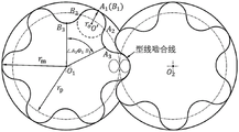
FIG. 3 rotor profiles and parameters of the present invention Schematic diagram of the geometrical meaning of (1);
FIG. 4 rotor profiles and parameters of the present invention Schematic diagram of the geometrical meaning of (1);
FIG. 5(a) is a schematic view of a three-dimensional rotor structure formed by the rotor profile of the present invention;
FIG. 5(b) is a schematic view of the leakage path between rotors formed by the rotor profile of the present invention;
FIG. 6 is a schematic view of a 4-tooth rotor profile of the present invention.
Detailed Description
The present invention will be described in further detail with reference to the accompanying drawings.
Referring to fig. 1, in the original rotor profile, the arc segment a1A2Circular arc section B1B2Circular arc envelope line segment B2B3Circular arc envelope line segment A2A3Composed curve segment B3B2A1A2A3Single tooth profile forming the original rotor profile, this single tooth profile B3B2A1A2A3Origin O of wound rotor profile1Rotate Then is combined with the tooth form B3B2A1A2A3Repeating the steps for n times to form an original rotor profile, wherein n represents the tooth number of the profile, n is 6 in figure 1, and the arc section A is formed1A2And arc section B1B2With respect to O1A1Symmetrical, circular arc envelope line segment B2B3And the arc envelope line segment A2A3With respect to O1A1Symmetrical, circular arc segment A1A2And the arc envelope line segment A2A3Engaged with each other, circular arc section B1B2And the arc envelope line segment B2B3The parameter determining the shape of said curve segment is the outer diameter r of the rotor profilemCenter distance | O1O2L and the number of teeth n of the rotor, thereby causing the number of the designable parameters of the rotor profile to be small, and the symmetry of the original profile causes the leakage channel formed between the rotors to be as shown in fig. 2(a) and 2(b), and as can be seen from the figure, the two leakage channels have the same shape, the resistance of the air flow passing through the two leakage channels is small, and the leakage amount is large。
In order to solve the problems of small quantity of designable parameters and large leakage quantity of the original rotor profile, as shown in fig. 3, the invention adopts the arc section A of the original rotor profile1A2And arc section B1B2Respectively changed into elliptical arc sections A1A2And an elliptical arc section B1B2Corresponding to the elliptical arc section A1A2Engaged curve segment A2A3Envelope segment modified to correspond to ellipse, and elliptical arc segment B1B2Engaged curve segment B2B3Instead, the envelope segment of the corresponding ellipse. In order to make the molded line in an asymmetric state, the rotor molded line of the invention is provided with an elliptical arc section A1A2Length of long and short axis and elliptic arc section B1B2The length of the major and minor axes of (a) is taken to be different values.
Single tooth profile B of the twisted lobe roots compressor rotor profile of the present invention shown in fig. 3-43B2A1A2A3Elliptic arc sections A connected in sequence from head to tail1A2Oval arc section B1B2Line segment B of ellipse envelope2B3Elliptical envelope line segment A2A3And (4) forming.
Twisted blade Roots compressor rotor profile is formed by single-tooth profile B3B2A1A2A3Origin O of wound rotor profile1Rotate Then is combined with the tooth form B3B2A1A2A3This is repeated n times end to end, where n represents the number of teeth of the profile, and n is taken to be 6 in fig. 3.
The twisted lobe roots compressor rotor profiles of the present invention illustrated in fig. 3-4 provide for proper meshing during rotational meshing, curve segment a1A2And curve segment A2A3Engaged, curve segment B1B2And curve segment B2B3And (4) meshing.
Rotor profile composed ofCenter distance | O1O2L, number of rotor teeth n, radius of addendum circle rmOval arc segment A1A2Length of major axis of Elliptic arc section B1B2Length of major axis of
 And ∠ B1O1B3-∠A1O1A3=αAsymmetricIs uniquely determined.
The elliptic arc section A of the twisted blade Roots compressor rotor profile1A2The parameter equation of (1) is as follows:


the solution is as follows:
from the above formula, parameter Is about a parameter rm、
 |O1O2Function of | binding Point A1Coordinate (r) ofm0), and further can obtain
 At this time, ∠ A1O1A2To be related to parameter rm、
 |O1O2Function of | ∠ A1O1A2At the same time, the following relationship should be satisfied,

the solution is as follows:

from the above equation, the left side of the equation is with respect to the parameter rm、 |O1O2| function, right hand side about parameter αAsymmetricN, where rm,
 |O1O2|,αAsymmetricAnd n is a design parameter. From this, parameters can be obtained
 To obtain an elliptical arc segment A1A2Complete parametric equations of (2).
The elliptical envelope line segment A of the twisted blade Roots compressor rotor profile2A3With an elliptical arc segment A1A2Meshing, the parameter equation is:

into an elliptical arc section A1A2The parameter equation of (2):

it is possible to obtain,
the relationship between α and θ can be derived from the meshing theorem, and is represented as:

wherein the parameters With an elliptical arc segment A1A2The same name parameter in (1) is the same parameter.
The elliptic arc section B of the twisted lobe Roots compressor rotor profile1B2Is solved and the elliptic arc segment A1A2The solving process is the same, except that The specific solving process is as follows:
the parameter equation is as follows:


the solution is as follows:

from the above formula, parameter Is about a parameter rm、
 |O1O2Function of, | binding point B1Coordinate (r) ofm0), and further can obtain
 At this time, ∠ B1O1B2To be related to parameter rm、
 |O1O2Function of | ∠ B1O1B2At the same time, the following relationship should be satisfied,

the solution is as follows:
from the above equation, the left side of the equation is with respect to the parameter rm、|O1O2| function, right hand side about parameter αAsymmetricN, where rm, |O1O2|,αAsymmetricAnd n is a design parameter. From this, the parameter b can be obtainedB1B2To obtain an elliptical arc segment B1B2Complete parametric equations of (2).
The elliptic envelope segment B of the twisted lobe Roots compressor rotor profile2B3And an elliptical arc section B1B2Meshing, the parameter equation is:

into an elliptical arc section B1B2The parameter equation of (2):
it is possible to obtain,

the relationship between α and θ can be derived from the meshing theorem, and is represented as:

wherein the parameters And an elliptical arc section B1B2The same name parameter in (1) is the same parameter.
Sequentially connecting the head and the tail of the elliptic enveloping line segment B3B2Oval arc section B2B1Oval arc segment A1A2Elliptical envelope line segment A2A3And forming a complete single-tooth profile of the rotor profile of the twisted-lobe roots compressor.
The three-dimensional configuration of the rotors and the leakage paths between the rotors formed by the twisted lobe roots rotor profile of the present invention are shown in fig. 5(a) and 5 (b). It can be seen that, because the rotor profile of the twisted-lobe roots compressor adopts an asymmetric design, the leakage channel formed between the rotors is in a large and small state, the smaller leakage channel area is smaller than that of the original rotor profile, and the flow resistance of the working medium is mainly determined by the smallest leakage channel area.
The rotor profile of the twisted-lobe roots compressor is formed after the number of teeth n is 4, and is shown in fig. 6.
The design process in the specific application of the invention is as follows:
1. the rotor center distance | O is optimized according to the volume and the air extraction rate1O2L, number of rotor teeth n, radius of addendum circle rm。
2. The elliptical arc section A is preferably selected according to the requirements of gas tightness, stress performance and the like1A2Major axis length a ofA1A2Oval arc section B1B2Major axis length a ofB1B2Central corner angle difference α of combined curve composed of two elliptic arcs and their envelope linesAsymmetric。
3. The solution of the curve is performed using the preferred parameters described above.
The asymmetric elliptical twisted Roots rotor profile provided by the invention is composed of an ellipse and an envelope line thereof, the defect that the design parameter space of the original rotor profile of the arc twisted Roots compressor is insufficient is overcome, and the single-tooth-shaped asymmetric design led out from the asymmetric twisted Roots compressor can effectively inhibit leakage between working cavities and improve the overall performance of the twisted Roots compressor or expander.
Compared with other conventional pump types, the pump has the advantages of few easily-damaged parts, compact structure, high air suction rate, no surge, low vibration noise and the like.
The above description is only a preferred embodiment of the present invention, and is not intended to limit the technical solution of the present invention, and it should be understood by those skilled in the art that the technical solution can be modified and replaced by a plurality of simple modifications and replacements without departing from the spirit and principle of the present invention, and the modifications and replacements also fall within the protection scope defined by the claims.
Claims (6)
1. The utility model provides an asymmetric oval type roots rotor of turning round leaf which characterized in that: single tooth profile B of rotor profile3B2A1A2A3Elliptic arc sections A connected in sequence from head to tail1A2Oval arc section B1B2Line segment B of ellipse envelope2B3Elliptical envelope line segment A2A3Composition is carried out;
the two rotors can be correctly meshed in the rotating meshing process, wherein the curve section A of one rotor1A2Curve segment a with another rotor2A3Are correspondingly engaged with each other, curve section B1B2And curve segment B2B3Mutually correspondingly engaged, elliptical envelope line segment A2A3With an elliptical arc segment A1A2Mutually correspondingly engaged, elliptical envelope line segment B2B3And an elliptical arc section B1B2Are correspondingly engaged with each other;
elliptic arc section A1A2Length of long and short axis and elliptic arc section B1B2The length of the long and short axes is taken as different values;
the complete rotor profile is formed by a single-tooth profile B3B2A1A2A3Origin O of wound rotor profile1Rotate Then is combined with the tooth form B3B2A1A2A3And repeating the steps for n times in an end-to-end manner, wherein n represents the number of teeth of the molded line.
2. The asymmetric elliptical, twisted roots rotor of claim 1, wherein:
elliptic arc section A1A2The parameter equation of (1) is as follows:
given by the following geometric relationship, point A2Located in an elliptical arc segment A1A2Up and from the origin O1A distance of rpWherein the pitch circle radius rpIs center distance | O1O2Half of l, the concrete solving equation is:

the solution is as follows:

parameters in the above formula Is about a parameter rm、
 |O1O2Function of | binding Point A1Coordinate (r) ofm0), and further can obtain
 ∠A1O1A2To be related to parameter rm、
 |O1O2Function of | ∠ A1O1A2Simultaneously satisfies the following relations:

solving to obtain:

in the above formula, the left side of the equation relates to the parameter rm、|O1O2| function, right hand side about parameter αAsymmetricN, where rm, |O1O2|,αAsymmetricN is a design parameter, thereby obtaining a parameterTo obtain an elliptical arc segment A1A2Complete parametric equations of (2).
3. The asymmetric elliptical, twisted roots rotor of claim 2, wherein:
elliptical envelope line segment A2A3The parameter equation of (1) is as follows:
into an elliptical arc section A1A2The parameter equation of (2):
it is possible to obtain,

the relationship between α and θ is derived from the meshing theorem and is expressed as:

wherein the parameters With an elliptical arc segment A1A2The same name parameter in (1) is the same parameter.
4. The asymmetric elliptical, twisted roots rotor of claim 1, wherein:
elliptic arc section B1B2The parameter equation of (1) is as follows:

given by the following geometric relationship, point B2Located in an elliptical arc segment B1B2Up and from the origin O1A distance of rpThe solution equation is:

the solution is as follows:

from the above formula, parameterIs about a parameter rm、 |O1O2Function of, | binding point B1Coordinate (r) ofm0), and further can obtain
 At this time, ∠ B1O1B2To be related to parameter rm、
 |O1O2Function of | ∠ B1O1B2Simultaneously satisfies the following relations:

the solution is as follows:

from the above equation, the left side of the equation is with respect to the parameter rm、 |O1O2| function, right hand side about parameter αAsymmetricN, where rm,|O1O2|,αAsymmetricN is a design parameter;
from this, parameters are obtained To obtain an elliptical arc segment B1B2Complete parametric equations of (2).
5. The asymmetric elliptical, twisted roots rotor of claim 4, wherein:
elliptical envelope line segment B2B3The parameter equation is as follows:

into an elliptical arc section B1B2The parameter equation of (2):

it is possible to obtain,
the relationship between α and θ is derived from the meshing theorem and is expressed as:

wherein the parameters And an elliptical arc section B1B2The same name parameter in (1) is the same parameter.
6. A compressor or expander having an asymmetric elliptical twisted roots rotor as claimed in any one of claims 1 to 5.
Priority Applications (1)
| Application Number | Priority Date | Filing Date | Title |
|---|---|---|---|
| CN201911061041.0A CN110762004B (en) | 2019-11-01 | 2019-11-01 | Asymmetric elliptic twisted-blade roots rotor, compressor and expander |
Applications Claiming Priority (1)
| Application Number | Priority Date | Filing Date | Title |
|---|---|---|---|
| CN201911061041.0A CN110762004B (en) | 2019-11-01 | 2019-11-01 | Asymmetric elliptic twisted-blade roots rotor, compressor and expander |
Publications (2)
| Publication Number | Publication Date |
|---|---|
| CN110762004A true CN110762004A (en) | 2020-02-07 |
| CN110762004B CN110762004B (en) | 2021-01-19 |
Family
ID=69335849
Family Applications (1)
| Application Number | Title | Priority Date | Filing Date |
|---|---|---|---|
| CN201911061041.0A Active CN110762004B (en) | 2019-11-01 | 2019-11-01 | Asymmetric elliptic twisted-blade roots rotor, compressor and expander |
Country Status (1)
| Country | Link |
|---|---|
| CN (1) | CN110762004B (en) |
Cited By (4)
| Publication number | Priority date | Publication date | Assignee | Title |
|---|---|---|---|---|
| CN111997895A (en) * | 2020-09-04 | 2020-11-27 | 兰州理工大学 | Method and system for preparing multi-blade cam rotor |
| CN112555152A (en) * | 2020-10-30 | 2021-03-26 | 西安交通大学 | Twisted-blade Roots rotor and design method thereof, compressor and expander |
| CN112943605A (en) * | 2021-01-14 | 2021-06-11 | 西安交通大学 | Asymmetric twisted-blade Roots rotor and design method thereof, compressor and expander |
| CN113550900A (en) * | 2021-08-19 | 2021-10-26 | 爱景节能科技(上海)有限公司 | Twisted-blade roots rotor profile with different tooth ratios |
Citations (4)
| Publication number | Priority date | Publication date | Assignee | Title |
|---|---|---|---|---|
| CN106194716A (en) * | 2016-09-18 | 2016-12-07 | 中国石油大学(华东) | A kind of SANYE oval arc-shaped cam follower |
| CN106194729A (en) * | 2016-09-18 | 2016-12-07 | 中国石油大学(华东) | A kind of oval arc-shaped roots rotor |
| CN108799111A (en) * | 2018-01-09 | 2018-11-13 | 中国石油大学(华东) | A kind of asymmetry roots rotor |
| JP2019127874A (en) * | 2018-01-24 | 2019-08-01 | 株式会社アンレット | Root type vacuum pump |
-
2019
- 2019-11-01 CN CN201911061041.0A patent/CN110762004B/en active Active
Patent Citations (4)
| Publication number | Priority date | Publication date | Assignee | Title |
|---|---|---|---|---|
| CN106194716A (en) * | 2016-09-18 | 2016-12-07 | 中国石油大学(华东) | A kind of SANYE oval arc-shaped cam follower |
| CN106194729A (en) * | 2016-09-18 | 2016-12-07 | 中国石油大学(华东) | A kind of oval arc-shaped roots rotor |
| CN108799111A (en) * | 2018-01-09 | 2018-11-13 | 中国石油大学(华东) | A kind of asymmetry roots rotor |
| JP2019127874A (en) * | 2018-01-24 | 2019-08-01 | 株式会社アンレット | Root type vacuum pump |
Non-Patent Citations (3)
| Title |
|---|
| 刘瑞青 等: "直叶与扭叶罗茨真空泵转子的性能分析", 《机械设计与制造》 * |
| 王君 等: "新型椭圆弧型罗茨转子的几何理论及其性能分析", 《中国石油大学学报(自然科学版)》 * |
| 龚建华: "一种新的系列化罗茨泵转子型线", 《真空科学与技术》 * |
Cited By (6)
| Publication number | Priority date | Publication date | Assignee | Title |
|---|---|---|---|---|
| CN111997895A (en) * | 2020-09-04 | 2020-11-27 | 兰州理工大学 | Method and system for preparing multi-blade cam rotor |
| CN111997895B (en) * | 2020-09-04 | 2021-04-02 | 兰州理工大学 | Method and system for preparing multi-blade cam rotor |
| CN112555152A (en) * | 2020-10-30 | 2021-03-26 | 西安交通大学 | Twisted-blade Roots rotor and design method thereof, compressor and expander |
| CN112943605A (en) * | 2021-01-14 | 2021-06-11 | 西安交通大学 | Asymmetric twisted-blade Roots rotor and design method thereof, compressor and expander |
| CN112943605B (en) * | 2021-01-14 | 2022-07-12 | 西安交通大学 | Asymmetric twisted-blade Roots rotor and design method thereof, compressor and expander |
| CN113550900A (en) * | 2021-08-19 | 2021-10-26 | 爱景节能科技(上海)有限公司 | Twisted-blade roots rotor profile with different tooth ratios |
Also Published As
| Publication number | Publication date |
|---|---|
| CN110762004B (en) | 2021-01-19 |
Similar Documents
| Publication | Publication Date | Title |
|---|---|---|
| CN110762004B (en) | Asymmetric elliptic twisted-blade roots rotor, compressor and expander | |
| CN108050069B (en) | Low-leakage full-smooth screw rotor | |
| CN108930650A (en) | A kind of double end claw pump rotor and its molded line | |
| CN108757464B (en) | Straight claw rotor of claw type vacuum pump and molded line design method thereof | |
| CN203189267U (en) | Conjugated internal-external cycloid involute-type rotor of roots vacuum pump | |
| CN113153742B (en) | Variable-line double-screw rotor and design method thereof | |
| CN112555154B (en) | Full-smooth self-meshing dry screw vacuum pump and rotor thereof | |
| CN110762011A (en) | Claw type pump rotor and claw type pump | |
| CN108757452A (en) | A kind of flute profile of high pressure ratio double-screw compressor rotor | |
| CN103603805A (en) | Rotor profile of double-screw compressor | |
| CN107084131A (en) | A kind of complete smooth screw rotor based on eccentric circle involute | |
| CN105257537B (en) | A kind of rotor end-face flute profile of three teeth helical-lobe compressor | |
| CN110645172B (en) | Screw vacuum pump rotor and screw vacuum pump | |
| CN108019348B (en) | Screw rotor comprising elliptical arcs | |
| CN106438358B (en) | A kind of conical screw rotor of self-balancing | |
| CN106948863B (en) | Full-smooth asymmetric double-claw rotor | |
| CN110685909B (en) | Double-screw rotor, compressor and expander | |
| CN210218105U (en) | Eccentric involute Roots rotor | |
| CN110878754A (en) | Two-blade rotor profile of Roots vacuum pump | |
| CN108343605B (en) | Three-jaw type vacuum pump | |
| CN110685906B (en) | Roots pump rotor and roots pump | |
| CN216691451U (en) | Tooth profile curve of pair of male and female rotors, male and female rotors and screw compressor | |
| CN205172940U (en) | Tridentate helical -lobe compressor's rotor terminal surface flute profile | |
| CN111779674B (en) | Rotor molded line of multi-lobe Roots pump | |
| CN113550900B (en) | Twisted-blade roots rotor profile with different tooth ratios |
Legal Events
| Date | Code | Title | Description |
|---|---|---|---|
| PB01 | Publication | ||
| PB01 | Publication | ||
| SE01 | Entry into force of request for substantive examination | ||
| SE01 | Entry into force of request for substantive examination | ||
| GR01 | Patent grant | ||
| GR01 | Patent grant |