CN110757536B - Plate cutting device - Google Patents
Plate cutting device Download PDFInfo
- Publication number
- CN110757536B CN110757536B CN201911032155.2A CN201911032155A CN110757536B CN 110757536 B CN110757536 B CN 110757536B CN 201911032155 A CN201911032155 A CN 201911032155A CN 110757536 B CN110757536 B CN 110757536B
- Authority
- CN
- China
- Prior art keywords
- fixedly connected
- rotating shaft
- cutting
- groove
- pushing
- Prior art date
- Legal status (The legal status is an assumption and is not a legal conclusion. Google has not performed a legal analysis and makes no representation as to the accuracy of the status listed.)
- Active
Links
Images


Classifications
-
- B—PERFORMING OPERATIONS; TRANSPORTING
- B26—HAND CUTTING TOOLS; CUTTING; SEVERING
- B26D—CUTTING; DETAILS COMMON TO MACHINES FOR PERFORATING, PUNCHING, CUTTING-OUT, STAMPING-OUT OR SEVERING
- B26D1/00—Cutting through work characterised by the nature or movement of the cutting member or particular materials not otherwise provided for; Apparatus or machines therefor; Cutting members therefor
- B26D1/01—Cutting through work characterised by the nature or movement of the cutting member or particular materials not otherwise provided for; Apparatus or machines therefor; Cutting members therefor involving a cutting member which does not travel with the work
- B26D1/12—Cutting through work characterised by the nature or movement of the cutting member or particular materials not otherwise provided for; Apparatus or machines therefor; Cutting members therefor involving a cutting member which does not travel with the work having a cutting member moving about an axis
- B26D1/14—Cutting through work characterised by the nature or movement of the cutting member or particular materials not otherwise provided for; Apparatus or machines therefor; Cutting members therefor involving a cutting member which does not travel with the work having a cutting member moving about an axis with a circular cutting member, e.g. disc cutter
- B26D1/157—Cutting through work characterised by the nature or movement of the cutting member or particular materials not otherwise provided for; Apparatus or machines therefor; Cutting members therefor involving a cutting member which does not travel with the work having a cutting member moving about an axis with a circular cutting member, e.g. disc cutter rotating about a movable axis
- B26D1/18—Cutting through work characterised by the nature or movement of the cutting member or particular materials not otherwise provided for; Apparatus or machines therefor; Cutting members therefor involving a cutting member which does not travel with the work having a cutting member moving about an axis with a circular cutting member, e.g. disc cutter rotating about a movable axis mounted on a movable carriage
-
- B—PERFORMING OPERATIONS; TRANSPORTING
- B25—HAND TOOLS; PORTABLE POWER-DRIVEN TOOLS; MANIPULATORS
- B25H—WORKSHOP EQUIPMENT, e.g. FOR MARKING-OUT WORK; STORAGE MEANS FOR WORKSHOPS
- B25H1/00—Work benches; Portable stands or supports for positioning portable tools or work to be operated on thereby
- B25H1/08—Work benches; Portable stands or supports for positioning portable tools or work to be operated on thereby with provision for attachment of work holders
-
- B—PERFORMING OPERATIONS; TRANSPORTING
- B25—HAND TOOLS; PORTABLE POWER-DRIVEN TOOLS; MANIPULATORS
- B25H—WORKSHOP EQUIPMENT, e.g. FOR MARKING-OUT WORK; STORAGE MEANS FOR WORKSHOPS
- B25H1/00—Work benches; Portable stands or supports for positioning portable tools or work to be operated on thereby
- B25H1/14—Work benches; Portable stands or supports for positioning portable tools or work to be operated on thereby with provision for adjusting the bench top
- B25H1/18—Work benches; Portable stands or supports for positioning portable tools or work to be operated on thereby with provision for adjusting the bench top in inclination
-
- B—PERFORMING OPERATIONS; TRANSPORTING
- B26—HAND CUTTING TOOLS; CUTTING; SEVERING
- B26D—CUTTING; DETAILS COMMON TO MACHINES FOR PERFORATING, PUNCHING, CUTTING-OUT, STAMPING-OUT OR SEVERING
- B26D5/00—Arrangements for operating and controlling machines or devices for cutting, cutting-out, stamping-out, punching, perforating, or severing by means other than cutting
- B26D5/02—Means for moving the cutting member into its operative position for cutting
- B26D5/06—Means for moving the cutting member into its operative position for cutting by electrical means
-
- B—PERFORMING OPERATIONS; TRANSPORTING
- B26—HAND CUTTING TOOLS; CUTTING; SEVERING
- B26D—CUTTING; DETAILS COMMON TO MACHINES FOR PERFORATING, PUNCHING, CUTTING-OUT, STAMPING-OUT OR SEVERING
- B26D7/00—Details of apparatus for cutting, cutting-out, stamping-out, punching, perforating, or severing by means other than cutting
- B26D7/01—Means for holding or positioning work
- B26D7/02—Means for holding or positioning work with clamping means
- B26D7/025—Means for holding or positioning work with clamping means acting upon planar surfaces
-
- B—PERFORMING OPERATIONS; TRANSPORTING
- B26—HAND CUTTING TOOLS; CUTTING; SEVERING
- B26D—CUTTING; DETAILS COMMON TO MACHINES FOR PERFORATING, PUNCHING, CUTTING-OUT, STAMPING-OUT OR SEVERING
- B26D7/00—Details of apparatus for cutting, cutting-out, stamping-out, punching, perforating, or severing by means other than cutting
- B26D7/20—Cutting beds
Landscapes
- Engineering & Computer Science (AREA)
- Mechanical Engineering (AREA)
- Life Sciences & Earth Sciences (AREA)
- Forests & Forestry (AREA)
- Processing Of Stones Or Stones Resemblance Materials (AREA)
Abstract
The invention discloses a plate cutting device, which comprises an upper workbench and a lower workbench, wherein the upper workbench is provided with a first chute, the first sliding chute is connected with a transverse moving mechanism in a sliding way, a first electric push rod is fixedly connected below the transverse moving mechanism, the lower part of the first electric push rod is fixedly connected with a cutting machine, the rear part of the upper workbench is connected with a pushing mechanism in a sliding way, the lower workbench is provided with a cutting table, the bottom of the cutting table is connected with the rotating mechanism in a sliding way, the two sides of the cutting table are fixedly connected with the clamping mechanism, the plate is rotated by a certain angle through the rotating mechanism, the cutting machine can move left and right through the transverse moving mechanism, the cutting machine can move up and down through the first electric push rod, the cutting machine can move back and forth through the pushing mechanism, and the cutting machine is simple in structure, high in practicability and high in novelty.
Description
Technical Field
The invention relates to the technical field of plate cutting, in particular to a plate cutting device.
Background
Plate cutting is an essential production process in the fields of life, industrial production and building, and the plate cutting is used for cutting a plate into a shape which the plate wants to obtain and is used in different occasions.
The existing cutting to the plate is mainly to cut the plate by a manual handheld cutting machine, or to cut the plate by a special machine tool, firstly to clamp and position the plate and then to cut the plate by the cutting machine, and the cutting machine can be moved to cut the fixed plate.
However, the prior art can not cut the plate in an inclined way, and can not obtain the plate with the inclined surface; the cutting of the sheet material at the desired position is not possible either.
Disclosure of Invention
The object of the present invention is to provide a panel cutting device that overcomes the above-mentioned drawbacks of the prior art.
In order to achieve the purpose, the invention provides the following technical scheme: the utility model provides a panel cutting device, includes workstation and lower workstation, be equipped with first spout on the workstation, sliding connection lateral shifting mechanism in the first spout, the first electric putter of lateral shifting mechanism below fixed connection, the below fixed connection cutting machine of first electric putter, the rear sliding connection pushing mechanism of workstation, be equipped with the cutting bed down on the workstation, the bottom sliding connection rotary mechanism of cutting bed, the both sides fixed connection clamping mechanism of cutting bed.
Preferably, the lateral shifting mechanism includes a first groove, the first groove is a hollow arrangement, a rack is slidably connected in the first groove, the upper portion of the rack is engaged with a gear, the gear is fixedly connected to a first rotating shaft, the first rotating shaft is fixedly connected to the output end of a rotating motor, the rotating motor is fixedly connected to one side of the first groove, and the lower portion of the rack is fixedly connected to a first electric push rod.
Preferably, the pushing mechanism includes a pushing case, a pushing motor is arranged in the pushing case, the pushing motor is fixedly connected to the support column, the output end of the pushing motor penetrates through the support column and is fixedly connected to the second rotating shaft, the second rotating shaft is fixedly connected to the first connecting rod, the first connecting rod is slidably connected to the second connecting rod through the third rotating shaft, the other end of the second connecting rod is slidably connected to the connecting plate through the fourth rotating shaft, the connecting plate is slidably connected to the second chute, the second chute is arranged on the fixing plate, the other end of the connecting plate is fixedly connected to the push-pull rod, and the other end of the push-pull rod penetrates through the pushing case and is fixedly connected to the rotating motor.
Preferably, rotary mechanism includes second electric putter, second electric putter's output sliding connection in the bottom of cutting bed, second electric putter's right side two bracing pieces of bottom symmetry fixed connection of cutting bed, two sliding connection fifth axis of rotation between the bracing piece, the bottom of cutting bed is equipped with the second recess, the fifth axis of rotation with second recess sliding connection.
Preferably, a plurality of convex blocks are fixedly connected to the cutting table, and the convex blocks are uniformly distributed along the X, Y axial side of the cutting table.
Preferably, the clamping mechanism comprises two symmetrical cylinders, wherein the two cylinders are fixedly connected with the cutting table, and the output ends of the two cylinders are fixedly connected with the rubber gasket.
According to the invention, a plate to be cut is clamped through the clamping mechanism, the plate is rotated by a certain angle through the rotating mechanism, the cutting machine can be moved left and right through the transverse moving mechanism, the cutting machine can move up and down through the first electric push rod, and the cutting machine can move back and forth through the pushing mechanism.
Drawings
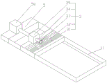
FIG. 1 is a schematic structural view of the present invention;
FIG. 2 is a schematic view of the lateral shifting mechanism of the present invention;
FIG. 3 is a schematic view of the pushing mechanism of the present invention;
FIG. 4 is a schematic view of the rack position of the present invention;
FIG. 5 is a bump distribution diagram of the present invention.
In the figure: the cutting device comprises an upper workbench 1, a lower workbench 2, a cutting table 21, a second groove 211, a protruding block 212, a first chute 11, a transverse moving mechanism 3, a first groove 31, a rack 32, a gear 33, a first rotating shaft 34, a rotating motor 35, a first electric push rod 4, a cutting machine 41, a pushing mechanism 5, a pushing case 50, a pushing motor 501, a supporting column 502, a second rotating shaft 503, a first connecting rod 504, a third rotating shaft 505, a second connecting rod 506, a fourth rotating shaft 507, a connecting plate 508, a second chute 509, a fixing plate 510, a push-pull rod 511, a rotating mechanism 6, a second electric push rod 61, a supporting rod 62, a fifth rotating shaft 63, a clamping mechanism 7, an air cylinder 71 and a rubber gasket 72.
Detailed Description
The technical solutions in the embodiments of the present invention will be clearly and completely described below with reference to the drawings in the embodiments of the present invention, and it is obvious that the described embodiments are only a part of the embodiments of the present invention, and not all of the embodiments. All other embodiments, which can be derived by a person skilled in the art from the embodiments given herein without making any creative effort, shall fall within the protection scope of the present invention.
Referring to fig. 1-5, the present invention provides a technical solution: the utility model provides a panel cutting device, including last workstation 1 and lower workstation 2, be equipped with first spout 11 on the last workstation 1, sliding connection lateral shifting mechanism 3 in first spout 11, the first electric putter 4 of 3 below fixed connection of lateral shifting mechanism, the below fixed connection cutting machine 41 of first electric putter 4, the rear sliding connection pushing mechanism 5 of going up workstation 1, be equipped with cutting bed 21 on the lower workstation 2, the bottom sliding connection rotary mechanism 6 of cutting bed 21, the both sides fixed connection clamping mechanism 7 of cutting bed 21.
The transverse moving mechanism 3 comprises a first groove 31, the first groove 31 is hollow, a rack 32 is slidably connected in the first groove 31, the upper part of the rack 32 is engaged with a gear 33, the gear 33 is fixedly connected to a first rotating shaft 34, the first rotating shaft is fixedly connected to the output end of a rotating motor 35, the rotating motor 35 is fixedly connected to one side of the first groove 31, the lower part of the rack 32 is fixedly connected with a first electric push rod 4, the pushing mechanism 5 comprises a pushing case 50, a pushing motor 501 is arranged in the pushing case 50, the pushing motor 501 is fixedly connected to a supporting column 502, the output end of the pushing motor 501 penetrates through the supporting column 502 and is fixedly connected with a second rotating shaft 503, the second rotating shaft 503 is fixedly connected with a first connecting rod 504, the first connecting rod 504 is slidably connected with a second connecting rod 506 through a third rotating shaft 505, and the other end of the second connecting rod 506 is slidably, the connecting plate 508 is slidably connected to the second sliding chute 509, the second sliding chute 509 is disposed on the fixing plate 510, the other end of the connecting plate 508 is fixedly connected to the push-pull rod 511, the other end of the push-pull rod 511 penetrates through the pushing case 50 and is fixedly connected to the rotating motor 35, the rotating mechanism 6 includes a second electric push rod 61, the output end of the second electric push rod 61 is slidably connected to the bottom of the cutting table 21, the right side of the second electric push rod 61 and the bottom of the cutting table 21 are symmetrically and fixedly connected to two supporting rods 62, a fifth rotating shaft 63 is slidably connected between the two supporting rods 62, the bottom of the cutting table 21 is provided with a second groove 211, the fifth rotating shaft 63 is slidably connected to the second groove 211, the cutting table 21 is fixedly connected to a plurality of protruding blocks 212, the plurality of protruding blocks 212 are uniformly distributed along the X, Y axial side of the cutting table 21, the clamping, the output ends of the two air cylinders 71 are fixedly connected with rubber gaskets 72.
According to the invention, a plate is clamped by the air cylinder 71 and the rubber gasket 72 of the clamping mechanism 7, meanwhile, the rubber gasket 72 prevents the plate from being damaged when the plate is clamped, the cutting table 21 is rotated by a certain angle by the second electric push rod 61, the support rod 62 and the fifth rotating shaft 63 of the rotating mechanism 6, the cutting machine 41 can move left and right by the first groove 31, the rack 32, the gear 33 and the first rotating shaft 34 of the transverse moving mechanism 3, the cutting machine 41 can move front and back by the push motor 501, the support column 502, the second rotating shaft 503, the first connecting rod 504, the third rotating shaft 505, the second connecting rod 506, the fourth rotating shaft 507, the connecting plate 508, the second sliding groove 509 and the fixing plate 510 of the pushing mechanism 5, and the cutting machine can move up and down by the first electric.
The working principle and the using process of the invention are as follows: the sheet is placed into the cutting table 21, the starting cylinder 71 clamps the sheet, then the second electric push rod 61 is started, the cutting table 21 is rotated along the fifth rotating shaft 63, the second electric push rod 61 is slidably connected with the cutting table 21, so that the position of the second electric push rod 61 at the bottom of the cutting table 21 can be adjusted to adjust the inclination angle required to be cut, after the cutting table 21 is pushed up by the second electric push rod 61, the pushing motor 501 is started, the pushing motor 501 drives the second rotating shaft 503 to rotate, because the first connecting rod 504 is fixedly connected with the second rotating shaft 503, the first connecting rod 504 rotates, because the third rotating shaft 505 is slidably connected with the second connecting rod 506, the second connecting rod 506 rotates to drive the connecting plate 508 to move, because the connecting plate 508 is slidably connected with the second chute 509, the connecting plate 508 moves linearly in the second chute 509 to drive the push-pull rod 511 to move, promote the motion of rotating electrical machines 35, because rotating electrical machines 35 fixed connection is in first recess 31, so promote first recess 31 and move in first spout 11, start first electric putter 4 and drive cutting machine 41 downstream and cut around panel, accomplish the task to inclination panel. When the panel that need not cut the angle, just need not adjust cutting bed 21, the angle, thereby start rotating electrical machines 35 this moment and drive the rotation of gear 33 and make rack 32 move about first recess 31, because first recess 31 is cavity setting, so first electric putter 4 can be connected through hollow position in rack 32 below to can remove in first recess 31 and can control, the cutting of front and back to panel, because protruding piece 212 can maximize at will along X, Y axle side evenly distributed of cutting bed at will.
Although embodiments of the present invention have been shown and described, it will be appreciated by those skilled in the art that changes, modifications, substitutions and alterations can be made in these embodiments without departing from the principles and spirit of the invention, the scope of which is defined in the appended claims and their equivalents.
Claims (3)
1. The utility model provides a panel cutting device, includes workstation (1) and lower workstation (2), its characterized in that: the upper working table (1) is provided with a first sliding groove (11), the first sliding groove (11) is internally and slidably connected with a transverse moving mechanism (3), the transverse moving mechanism (3) is fixedly connected with a first electric push rod (4) below, the first electric push rod (4) is fixedly connected with a cutting machine (41) below, the upper working table (1) is provided with a rear sliding connection pushing mechanism (5), the lower working table (2) is provided with a cutting table (21), the cutting table (21) is slidably connected with a rotating mechanism (6) at the bottom, two clamping mechanisms (7) are fixedly connected with the two sides of the cutting table (21), the transverse moving mechanism (3) comprises a first groove (31), the first groove (31) is hollow, the first groove (31) is internally and slidably connected with a rack (32), and the upper part of the rack (32) is meshed with a gear (33), the gear (33) is fixedly connected to a first rotating shaft (34), the first rotating shaft is fixedly connected to the output end of a rotating motor (35), the rotating motor (35) is fixedly connected to one side of the first groove (31), the lower portion of the rack (32) is fixedly connected with a first electric push rod (4), the pushing mechanism (5) comprises a pushing case (50), a pushing motor (501) is arranged in the pushing case (50), the pushing motor (501) is fixedly connected to a supporting column (502), the output end of the pushing motor (501) penetrates through the supporting column (502) and is fixedly connected with a second rotating shaft (503), the second rotating shaft (503) is fixedly connected with a first connecting rod (504), the first connecting rod (504) is slidably connected to a second connecting rod (506) through a third rotating shaft (505), and the other end of the second connecting rod (506) is slidably connected with a connecting plate (508) through a fourth rotating shaft (507), the connecting plate (508) is connected with a second sliding chute (509) in a sliding way, the second sliding chute (509) is arranged on the fixed plate (510), the other end of the connecting plate (508) is fixedly connected with a push-pull rod (511), the other end of the push-pull rod (511) penetrates through the pushing case (50) and is fixedly connected with the rotating motor (35), the rotating mechanism (6) comprises a second electric push rod (61), the output end of the second electric push rod (61) is connected to the bottom of the cutting table (21) in a sliding manner, the right side of the second electric push rod (61) and the bottom of the cutting table (21) are symmetrically and fixedly connected with two supporting rods (62), a fifth rotating shaft (63) is connected between the two supporting rods (62) in a sliding way, the bottom of the cutting table (21) is provided with a second groove (211), and the fifth rotating shaft (63) is connected with the second groove (211) in a sliding mode.
2. A board cutting device according to claim 1, characterized in that: the cutting table (21) is fixedly connected with a plurality of convex blocks (212), and the convex blocks (212) are uniformly distributed along the X, Y axial side of the cutting table (21).
3. A board cutting device according to claim 1, characterized in that: clamping mechanism (7) include two cylinders (71) of symmetry, two equal fixed connection in cylinder (71) cutting bed (21), two the output of cylinder (71) is equal fixed connection rubber packing ring (72).
Priority Applications (1)
| Application Number | Priority Date | Filing Date | Title |
|---|---|---|---|
| CN201911032155.2A CN110757536B (en) | 2019-10-28 | 2019-10-28 | Plate cutting device |
Applications Claiming Priority (1)
| Application Number | Priority Date | Filing Date | Title |
|---|---|---|---|
| CN201911032155.2A CN110757536B (en) | 2019-10-28 | 2019-10-28 | Plate cutting device |
Publications (2)
| Publication Number | Publication Date |
|---|---|
| CN110757536A CN110757536A (en) | 2020-02-07 |
| CN110757536B true CN110757536B (en) | 2021-02-02 |
Family
ID=69334259
Family Applications (1)
| Application Number | Title | Priority Date | Filing Date |
|---|---|---|---|
| CN201911032155.2A Active CN110757536B (en) | 2019-10-28 | 2019-10-28 | Plate cutting device |
Country Status (1)
| Country | Link |
|---|---|
| CN (1) | CN110757536B (en) |
Families Citing this family (2)
| Publication number | Priority date | Publication date | Assignee | Title |
|---|---|---|---|---|
| CN113087376A (en) * | 2021-03-31 | 2021-07-09 | 深圳市鸿昇自动化设备有限公司 | Clamping equipment for cutting mobile phone screen |
| CN115122416B (en) * | 2022-07-04 | 2023-07-18 | 浙江机电职业技术学院 | Computer screen panel cutting device |
Citations (5)
| Publication number | Priority date | Publication date | Assignee | Title |
|---|---|---|---|---|
| JP4412792B2 (en) * | 2000-01-28 | 2010-02-10 | 富士重工業株式会社 | Method for cutting honeycomb core and mounting jig for cutting honeycomb core |
| CN204955145U (en) * | 2015-08-03 | 2016-01-13 | 福建盛达机器股份公司 | Five bridge type cut stone machines of numerical control |
| CN107471296A (en) * | 2017-09-05 | 2017-12-15 | 江苏宁泰模具有限公司 | A kind of environment-friendly type mould production cutting machine |
| CN108274503A (en) * | 2017-12-28 | 2018-07-13 | 贵州长顺八妹农副产品开发有限公司 | A kind of chip potato cutter of adjustable slice thickness |
| CN109015889A (en) * | 2018-08-06 | 2018-12-18 | 石纪康 | A kind of die-cutting machine facilitating adjustment cross cutting cutter position |
-
2019
- 2019-10-28 CN CN201911032155.2A patent/CN110757536B/en active Active
Patent Citations (5)
| Publication number | Priority date | Publication date | Assignee | Title |
|---|---|---|---|---|
| JP4412792B2 (en) * | 2000-01-28 | 2010-02-10 | 富士重工業株式会社 | Method for cutting honeycomb core and mounting jig for cutting honeycomb core |
| CN204955145U (en) * | 2015-08-03 | 2016-01-13 | 福建盛达机器股份公司 | Five bridge type cut stone machines of numerical control |
| CN107471296A (en) * | 2017-09-05 | 2017-12-15 | 江苏宁泰模具有限公司 | A kind of environment-friendly type mould production cutting machine |
| CN108274503A (en) * | 2017-12-28 | 2018-07-13 | 贵州长顺八妹农副产品开发有限公司 | A kind of chip potato cutter of adjustable slice thickness |
| CN109015889A (en) * | 2018-08-06 | 2018-12-18 | 石纪康 | A kind of die-cutting machine facilitating adjustment cross cutting cutter position |
Also Published As
| Publication number | Publication date |
|---|---|
| CN110757536A (en) | 2020-02-07 |
Similar Documents
| Publication | Publication Date | Title |
|---|---|---|
| CN110757536B (en) | Plate cutting device | |
| CN108637371B (en) | A kind of Furniture panel cutting machine convenient for clamping | |
| CN204413303U (en) | Groover | |
| CN210125780U (en) | Industrial automatic cutting machine | |
| CN210188687U (en) | Sawing machine for steel processing | |
| CN208944891U (en) | One kind is for handling tunnel joint bending machine | |
| CN203566797U (en) | Feeding mechanism of numerical control cut-to-size saw | |
| CN211104483U (en) | Pencil board forming device for processing pencil | |
| CN210633026U (en) | Sawing machine with adjustable go up and down | |
| CN216831389U (en) | Vertical shaft type woodworking router | |
| CN214109633U (en) | Multifunctional clamp for machining production | |
| CN209466291U (en) | A kind of glass fibre reinforced plastics rockbolts automatic angle cutting machine | |
| CN208649127U (en) | A kind of glass processing cutter device | |
| CN208005795U (en) | A kind of plasthetics processing raw material cutter device | |
| CN112536838A (en) | Cutting device is used in panel section production | |
| CN213437478U (en) | Novel hardware mould is with beveling device | |
| CN217386192U (en) | Industrial non-standard automatic control equipment | |
| CN210305980U (en) | Support device for pipe cutting machine | |
| CN108406951A (en) | A kind of structural lumber disconnecting device | |
| CN212761938U (en) | High-precision assembling machine for steel structure | |
| CN215699330U (en) | Cargo compartment door welding platform | |
| CN217858574U (en) | Steel bar cutting device for constructional engineering | |
| CN220445475U (en) | Turnover mechanism for capacitor welding | |
| CN219212656U (en) | Die cutting and changing device for die automatic calibration | |
| CN220112483U (en) | Trimming device for aluminum composite panel processing |
Legal Events
| Date | Code | Title | Description |
|---|---|---|---|
| PB01 | Publication | ||
| PB01 | Publication | ||
| SE01 | Entry into force of request for substantive examination | ||
| SE01 | Entry into force of request for substantive examination | ||
| GR01 | Patent grant | ||
| GR01 | Patent grant | ||
| TR01 | Transfer of patent right |
Effective date of registration: 20220519 Address after: 221300 506, block B, electronic industrial park, Pizhou Economic Development Zone, Xuzhou City, Jiangsu Province Patentee after: Xuzhou Bochuang Construction Development Group Co.,Ltd. Address before: No.88 Liaohe West Road, Pizhou Economic Development Zone, Xuzhou City, Jiangsu Province Patentee before: SU Normal University Semiconductor Materials and Equipment Research Institute (Pizhou) Co.,Ltd. |
|
| TR01 | Transfer of patent right |