CN110757024A - Spiral steel pipe welding robot - Google Patents
Spiral steel pipe welding robot Download PDFInfo
- Publication number
- CN110757024A CN110757024A CN201911151662.8A CN201911151662A CN110757024A CN 110757024 A CN110757024 A CN 110757024A CN 201911151662 A CN201911151662 A CN 201911151662A CN 110757024 A CN110757024 A CN 110757024A
- Authority
- CN
- China
- Prior art keywords
- gear
- traction
- plate
- welding
- motor
- Prior art date
- Legal status (The legal status is an assumption and is not a legal conclusion. Google has not performed a legal analysis and makes no representation as to the accuracy of the status listed.)
- Granted
Links
Images


Classifications
-
- B—PERFORMING OPERATIONS; TRANSPORTING
- B23—MACHINE TOOLS; METAL-WORKING NOT OTHERWISE PROVIDED FOR
- B23K—SOLDERING OR UNSOLDERING; WELDING; CLADDING OR PLATING BY SOLDERING OR WELDING; CUTTING BY APPLYING HEAT LOCALLY, e.g. FLAME CUTTING; WORKING BY LASER BEAM
- B23K31/00—Processes relevant to this subclass, specially adapted for particular articles or purposes, but not covered by only one of the preceding main groups
- B23K31/02—Processes relevant to this subclass, specially adapted for particular articles or purposes, but not covered by only one of the preceding main groups relating to soldering or welding
- B23K31/027—Making tubes with soldering or welding
-
- B—PERFORMING OPERATIONS; TRANSPORTING
- B23—MACHINE TOOLS; METAL-WORKING NOT OTHERWISE PROVIDED FOR
- B23K—SOLDERING OR UNSOLDERING; WELDING; CLADDING OR PLATING BY SOLDERING OR WELDING; CUTTING BY APPLYING HEAT LOCALLY, e.g. FLAME CUTTING; WORKING BY LASER BEAM
- B23K37/00—Auxiliary devices or processes, not specially adapted to a procedure covered by only one of the preceding main groups
- B23K37/04—Auxiliary devices or processes, not specially adapted to a procedure covered by only one of the preceding main groups for holding or positioning work
- B23K37/047—Auxiliary devices or processes, not specially adapted to a procedure covered by only one of the preceding main groups for holding or positioning work moving work to adjust its position between soldering, welding or cutting steps
-
- B—PERFORMING OPERATIONS; TRANSPORTING
- B23—MACHINE TOOLS; METAL-WORKING NOT OTHERWISE PROVIDED FOR
- B23P—METAL-WORKING NOT OTHERWISE PROVIDED FOR; COMBINED OPERATIONS; UNIVERSAL MACHINE TOOLS
- B23P23/00—Machines or arrangements of machines for performing specified combinations of different metal-working operations not covered by a single other subclass
-
- B—PERFORMING OPERATIONS; TRANSPORTING
- B23—MACHINE TOOLS; METAL-WORKING NOT OTHERWISE PROVIDED FOR
- B23K—SOLDERING OR UNSOLDERING; WELDING; CLADDING OR PLATING BY SOLDERING OR WELDING; CUTTING BY APPLYING HEAT LOCALLY, e.g. FLAME CUTTING; WORKING BY LASER BEAM
- B23K2101/00—Articles made by soldering, welding or cutting
- B23K2101/04—Tubular or hollow articles
- B23K2101/06—Tubes
Abstract
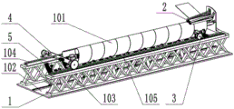
The invention provides a spiral steel pipe welding robot, comprising: the device comprises a welding machine frame, a steel plate bending device, a welding device, a traction device and a supporting device. The welding machine frame is an integral frame, other devices are arranged on the welding machine frame, the steel plate bending device processes a plate steel plate into a spiral steel plate, the welding device welds the weld joint of the spiral steel pipe, the traction device pulls the welded steel pipe forward, meanwhile, the traction device provides rotary power for the steel pipe, and the supporting device has the function of supporting the steel pipes with different pipe diameters. The invention can weld spiral steel pipes with different pipe diameters.
Description
Technical Field
The invention relates to the field of spiral steel pipe machining, in particular to a spiral steel pipe welding robot.
Background
Spiral steel pipe adds man-hour, needs to weld the spiral steel pipe with the crooked processing heliciform of panel steel sheet, and the tradition uses artificial processing mode to waste time and energy, and especially big pipe diameter steel sheet processing difficulty, patent application number 201821765503.8 discloses an automatic spiral welding machine, and this utility model can carry out effective welding to the spiral welding seam, but this utility model can't carry out bending treatment to large-scale panel steel sheet to can not adjust the welding length of steel pipe.
Disclosure of Invention
In order to solve the technical problems, the invention adopts the technical scheme that: a spiral steel pipe welding robot comprises a welding machine frame, a steel plate bending device, a welding device, a traction device and a supporting device; wherein the welding machine frame includes: the device comprises a base seat, an X-shaped support frame, a rack concave chute and a rack; the steel plate bending apparatus includes: the bending device comprises a bending transverse plate, a bending vertical plate, a rolling roller shaft, a roller shaft bracket, a fixing bolt, a fixing nut, a bracket auxiliary plate, a bending motor platform, a bending slide block, a bending chute, a bending motor, a motor driving gear, a motor driven gear, a bending connecting shaft, a transmission lower gear, a lower connecting plate, a middle gear, an upper connecting plate, a transmission driven gear, a transmission upper gear, a rear left transmission gear, a rear left driven gear, a rear left connecting plate, a rear middle gear, a rear bending connecting shaft, a rear right connecting plate, a rear right driven gear and a rear right transmission gear; the welding device includes: the welding device comprises a welding platform, a welding sliding block, a welding sliding chute, a welding motor platform, a welding feeding motor, a welding feeding gear, a welding feeding rack, a welding gear platform, a welding left motor, a welding right motor and a welding left gear; the traction device comprises: the traction device comprises a traction long plate, a traction moving motor platform, a traction moving motor, a traction moving gear, a traction rotating motor platform, a traction rotating motor, a traction shaft support, a traction transmission shaft, a traction driving bevel gear, a traction driven bevel gear, a traction central shaft, a traction connecting plate, a clamping motor mounting plate, a clamping motor, a thrust plate, a thrust bearing, a thrust sliding block, a clamping thrust plate, a clamping top plate and a clamping roller; the supporting device comprises: the support sliding chute, support radius regulating motor, support slider, slider connecting plate, radius regulating plate, steel pipe support, steel pipe roll, curved slider connecting plate, curved slider, curved spout, curved connecting plate.
The base of the welding machine frame is located at the lowest position of the welding machine frame, the number of the X-shaped support frames is two, the lower portions of the two X-shaped support frames are fixedly installed on two sides of the base, the number of the frame concave sliding grooves is two, the two frame concave sliding grooves are respectively installed on the upper portions of the two X-shaped support frames, and the frame rack is fixedly installed on the upper portion of the right X-shaped support frame.
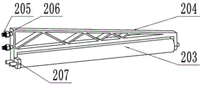
The steel sheet bending apparatus's crooked diaphragm both ends fixed mounting is between two X type support frames, crooked perpendicular fixed mounting of version is in the middle part of crooked diaphragm, crooked perpendicular version middle part has the mounting hole, roll roller and roller support have four groups, roll the roller rotation of roll roller and install on the roller support, two fixing bolt fixed mounting are at roller support side, fixing bolt wears to see through crooked perpendicular version mounting hole, fixation nut forms screw-thread fit with fixing bolt, and with roller support fixed mounting at crooked perpendicular version rear surface, the support attaches board fixed mounting on the roller support.
The bending motor platform is fixedly arranged on the first group of roll shaft supports through a bending vertical plate, the bending slider is fixedly arranged on the side edge of the bending motor platform, the bending chute is fixedly arranged on the front surface of the bending vertical plate, the bending slider and the bending chute form sliding fit, the bending motor is fixedly arranged on the upper surface of the bending motor platform, the motor driving gear is fixedly arranged on a rotating shaft of the bending motor, the motor driving gear and a motor driven gear form gear fit, the motor driven gear is fixedly arranged at one end of a bending connecting shaft, the bending connecting shaft is fixedly arranged on the rotating shaft of the first group of rolling rolls through the bending vertical plate, a transmission lower gear is fixedly arranged at the middle part of the bending connecting shaft, one end of a lower connecting plate is close to the transmission lower gear and is arranged at the middle part of the bending connecting shaft, the middle gear is rotatably arranged at the other end of the, one end of the upper connecting plate is rotatably installed at the other end of the lower connecting plate, the transmission driven gear and the intermediate gear form gear fit, the transmission driven gear is rotatably installed at the other end of the upper connecting plate, the transmission driven gear and the transmission upper gear form gear fit, and the transmission upper gear is fixedly installed on a rotating shaft of the second group of rolling roller shafts.
The rear left transmission gear is fixedly arranged on a rotating shaft at the other end of the second group of rolling roller shafts, the rear left transmission gear is in gear fit with the rear left driven gear, the rear left driven gear is fixedly and rotatably arranged on a bracket attached plate rotating shaft of the second group of roller shaft brackets, one end of a rear left connecting plate is rotatably arranged on the bracket attached plate rotating shaft, the other end of the rear left connecting plate is rotatably arranged on a rear bending connecting shaft, the rear left driven gear is in gear fit with a rear intermediate gear, the rear intermediate gear is rotatably arranged on the rear bending connecting shaft, one end of a rear right connecting plate is rotatably arranged on the rear bending connecting shaft, the other end of the rear right connecting plate is rotatably arranged on a bracket attached plate of a third group of roller shaft brackets, the rear right driven gear is in gear fit with the rear intermediate gear, the rear right driven gear is rotatably arranged on a bracket attached plate of a third group of roller shaft brackets, and the rear, and the rear right transmission gear is fixedly arranged on a rotating shaft of the third group of rolling roll shafts.
Welding set's welding slider fixed mounting is at the welding platform lower surface, the welding slider forms sliding fit with the concave type spout of frame, two welding spout fixed mounting welding platform upper surfaces, welding motor platform forms sliding fit with the welding spout, welding feed motor fixed mounting is at welding motor platform upper surface, welding feed gear fixed mounting is in the axis of rotation of welding feed motor, welding feed gear forms the gear cooperation with the welding feed rack, welding feed rack fixed mounting is at welding gear platform upper surface, welding gear platform fixed mounting is on welding platform, motor fixed mounting is on welding platform upper surface about the welding, gear fixed mounting is in the axis of rotation of motor about the welding about, gear forms the gear cooperation with the frame rack about the welding.
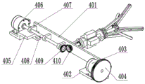
The traction device is characterized in that a traction long plate of the traction device is located between X-type supporting frames, a traction moving motor platform is fixedly installed at the right end of the traction long plate, the traction moving motor is fixedly installed on the upper surface of the traction moving motor platform, a traction moving gear is fixedly installed on a rotation shaft of the traction moving motor, the traction moving gear and a rack form gear fit, the traction rotating motor platform is fixedly installed at the left end of the traction long plate, the traction rotating motor is fixedly installed on the upper surface of the traction rotating motor platform, one end of a traction transmission shaft is fixedly installed on the rotation shaft of the traction rotating motor, the middle part of the traction transmission shaft forms sliding fit with three traction shaft supports, the traction shaft supports are fixedly installed on the front surface of the traction long plate, a traction driving bevel gear is fixedly installed at the other end of.
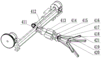
The traction driven bevel gear is fixedly arranged at one end of a traction central shaft, four mounting columns of the traction connecting plate are fixedly arranged on the rear surface of a traction long plate, the traction central shaft penetrates through a cone of the traction connecting plate, a clamping motor mounting plate is fixedly arranged on the end surface of the traction connecting plate, the traction central shaft penetrates through a clamping motor mounting plate, four clamping motors are fixedly arranged on four surfaces of the clamping motor mounting plate, a thrust plate is fixedly arranged on a telescopic shaft of the clamping motor, a thrust bearing is arranged between the thrust plate and a thrust sliding block, the thrust sliding block is slidably arranged on the traction central shaft, four clamping thrust plates are arranged, one end of each clamping thrust plate is rotatably arranged on the thrust sliding block, the other end of each clamping thrust plate is rotatably arranged in the middle of the clamping plate, one end of each clamping plate is rotatably arranged on a, the clamping roller is rotatably arranged at the other end of the clamping plate.
The support device is provided with nine groups, the support sliding chute of each group of support device is fixedly arranged on the upper surface of the base seat, the support radius adjusting motor is fixedly arranged on the upper surface of the base seat near the support sliding chute, one end of the support sliding block is fixedly arranged on a telescopic shaft of the support radius adjusting motor, the other end of the support sliding block and the support sliding chute form a sliding fit, one end of a sliding block connecting plate is rotatably arranged at the other end of the support sliding block, the other end of the sliding block connecting plate is rotatably arranged at one end of a radius adjusting plate, the middle part of the radius adjusting plate and a steel pipe support form a sliding fit, the steel pipe is rotatably arranged at the other end of the radius adjusting plate near the steel pipe, one end of a bent sliding block connecting plate is rotatably arranged at the other end of the radius, the arc of the bent sliding groove is closely matched with the arc of the steel pipe support, the bent sliding groove is fixedly installed on the steel pipe support, and the bent connecting plate is fixedly installed between the two groups of bent sliding blocks.
The invention has the beneficial effects that: the invention realizes the technical problem of welding the spiral steel pipe by manufacturing the large-diameter steel plate at the same time by the matching arrangement of the welding machine frame, the steel plate bending device, the welding device, the traction device and the supporting device.
Drawings
FIG. 1 is a front view of the present invention.
FIG. 2 is a side view of the present invention.
Fig. 3 is a schematic view of a roll shaft according to the present invention.
FIG. 4 is a schematic view of a steel plate bending apparatus according to the present invention.
FIG. 5 is a front gear set of the steel plate bending apparatus of the present invention.
FIG. 6 is a schematic view of a rear gear set of the steel plate bending apparatus according to the present invention.
FIG. 7 is a schematic view of a welding apparatus of the present invention.
Fig. 8 is a schematic front view of the traction device of the present invention.
Fig. 9 is a side schematic view of a draft gear of the present invention.
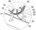
FIG. 10 is a schematic view of the supporting device of the present invention.
Reference numerals: 1-welding machine frame; 2-a steel plate bending device; 3-a welding device; 4-a traction device; 5-a support device; 101-a steel pipe; 102-a base seat; 103-X type support frame; 104-frame concave chute; 105-a rack gear; 201-bending a transverse plate; 202-bending vertical plate; 203-rolling roller shafts; 204-roller holder; 205-fixing bolts; 206-a fixing nut; 207-support attachment plate; 208-bending motor platform; 209-bending the slider; 210-a curved chute; 211-bending motor; 212-motor drive gear; 213-motor driven gear; 214-bending the connecting shaft; 215-drive lower gear; 216-lower connecting plate; 217-intermediate gear; 218-an upper connecting plate; 219-drive driven gear; 220-drive up gear; 221-rear left drive gear; 222-rear left slave gear; 223-rear left connecting plate; 224-rear intermediate gear; 225-rear bending connecting shaft; 226-rear right connector plate; 227-rear right slave gear; 228-rear right drive gear; 301-a welding platform; 302-welding the slider; 303-welding a chute; 304-welding the motor platform; 305-a welding feed motor; 306-welding the feed gear; 307-welding a feed rack; 308-welding the gear platform; 309-welding left and right motors; 310-welding left and right gears; 401-pulling the long plate; 402-traction moving motor platform; 403-traction movement motor; 404-traction movement gear; 405-a traction rotating electrical machine platform; 406-a traction rotating machine; 407-traction shaft support; 408-a traction drive shaft; 409-traction drive bevel gear; 410-traction driven bevel gear; 411-a central axis of traction; 412-a traction connection plate; 413-clamping the motor mounting plate; 414-a clamping motor; 415-a thrust plate; 416-a thrust bearing; 417-thrust slider; 418-clamping the thrust plate; 419-a clamping plate; 420-clamping the top plate; 421-clamping roller; 501-supporting sliding chutes; 502-support radius adjustment motor; 503-supporting the slide block; 504-a slider connection plate; 505-radius adjustment plate; 506-steel pipe supporting; 507, rolling the steel pipe; 508-curved slider connecting plates; 509-curved slider; 510-a curved chute; 511-bent connection plate.
Detailed Description
The present invention will be further described with reference to specific examples, which are illustrative of the invention and are not to be construed as limiting the invention.
Example (b): a spiral steel pipe welding robot as shown in fig. 1-10.
The base 102 of the welding machine frame 1 is positioned at the lowest part of the welding machine frame 1, the number of the X-shaped support frames 103 is two, the lower parts of the two X-shaped support frames 103 are fixedly arranged at two sides of the base 102, the number of the frame concave sliding grooves 104 is two, the two frame concave sliding grooves 104 are respectively arranged at the upper parts of the two X-shaped support frames 103, and the frame rack 105 is fixedly arranged at the upper part of the right X-shaped support frame 103.
Two ends of a bending transverse plate 201 of the steel plate bending device 2 are fixedly installed between two X-shaped supporting frames 103, a bending vertical plate 202 is vertically and fixedly installed in the middle of the bending transverse plate 201, a mounting hole is formed in the middle of the bending vertical plate 202, four groups of rolling rollers 203 and roller shaft supports 204 are arranged, the rolling rollers 203 are rotatably installed on the roller shaft supports 204, two fixing bolts 205 are fixedly installed on the side edges of the roller shaft supports 204, the fixing bolts 205 penetrate through the mounting holes of the bending vertical plate 202, fixing nuts 206 and the fixing bolts 205 form threaded fit, the roller shaft supports 204 are fixedly installed on the rear surfaces of the bending vertical plates 202, and support attaching plates 207 are fixedly installed on the roller shaft supports 204. The four sets of the rolling rollers 203 and the roller holders 204 bend the plate steel sheet.
The bending motor platform 208 penetrates through the bending vertical plate 202 and is fixedly installed on the first group of roller shaft brackets 204, the bending slider 209 is fixedly installed on the side edge of the bending motor platform 208, the bending chute 210 is fixedly installed on the front surface of the bending vertical plate 202, the bending slider 209 and the bending chute 210 form sliding fit, the bending motor 211 is fixedly installed on the upper surface of the bending motor platform 208, the motor driving gear 212 is fixedly installed on the rotating shaft of the bending motor 211, the motor driving gear 212 and the motor driven gear 213 form gear fit, the motor driven gear 213 is fixedly installed at one end of the bending connecting shaft 214, the bending connecting shaft 214 penetrates through the bending vertical plate 202 and is fixedly installed on the rotating shaft of the first group of rolling roller shafts 203, the transmission lower gear 215 is fixedly installed at the middle part of the bending connecting shaft 214, one end of the lower connecting plate 216 is close to the transmission lower gear 215 and is installed at the middle part of, the middle gear 217 forms a gear fit with the transmission lower gear 215, one end of the upper connecting plate 218 is rotatably installed at the other end of the lower connecting plate 216, the transmission slave gear 219 forms a gear fit with the middle gear 217, the transmission slave gear 219 is rotatably installed at the other end of the upper connecting plate 218, the transmission slave gear 219 forms a gear fit with the transmission upper gear 220, and the transmission upper gear 220 is fixedly installed on a rotating shaft of the second group of rolling roller shafts 203. The bending motor 211 provides power, and drives the four groups of rolling roller shafts 203 to do synchronous rotation motion through gear pair transmission, the steel plate is subjected to bending treatment through the four groups of rolling roller shafts 203, and the radius of the spiral steel pipe can be adjusted at the matching position of the bending vertical plate 202 by adjusting the fixing bolt 205 and the fixing nut 206.
A rear left transmission gear 221 is fixedly installed on a rotating shaft at the other end of the second group of rolling roller shafts 203, the rear left transmission gear 221 is in gear fit with a rear left driven gear 222, the rear left driven gear 222 is fixedly and rotatably installed on a rotating shaft of a bracket attachment plate 207 of the second group of roller shaft brackets 204, one end of a rear left connecting plate 223 is rotatably installed on the rotating shaft of the bracket attachment plate 207, the other end of the rear left connecting plate 223 is rotatably installed on a rear bending attachment shaft 225, the rear left driven gear 222 is in gear fit with a rear middle gear 224, the rear middle gear 224 is rotatably installed on the rear bending attachment shaft 225, one end of a rear right connecting plate 226 is rotatably installed on the rear bending attachment shaft 225, the other end of the rear right connecting plate 226 is rotatably installed on the bracket attachment plate 207 of the third group of roller shaft brackets 204, the rear right driven gear 227 is in gear fit with the rear middle gear 224, the rear right driven gear 227 is rotatably installed on, the rear right driven gear 227 is gear-fitted with a rear right transmission gear 228, and the rear right transmission gear 228 is fixedly mounted on the rotational shaft of the third group rolling roller shaft 203. The gear transmission between the rear left driving gear 221, the rear left driven gear 222, the rear intermediate gear 224, the rear right driven gear 227, and the rear right driving gear 228 may transmit the rotational motion of the second group of the rolling roller shafts 203 to the third group of the rolling roller shafts 203.
The welding device 3 is characterized in that a welding slider 302 is fixedly arranged on the lower surface of a welding platform 301, the welding slider 302 and a rack concave chute 104 form sliding fit, two welding chutes 303 are fixedly arranged on the upper surface of the welding platform 301, a welding motor platform 304 and the welding chutes 303 form sliding fit, a welding feed motor 305 is fixedly arranged on the upper surface of the welding motor platform 304, a welding feed gear 306 is fixedly arranged on a rotating shaft of the welding feed motor 305, the welding feed gear 306 and a welding feed rack 307 form gear fit, the welding feed rack 307 is fixedly arranged on the upper surface of a welding gear platform 308, the welding gear platform 308 is fixedly arranged on the welding platform 301, a welding left motor 309 and a welding right motor 309 are fixedly arranged on the upper surface of the welding platform 301, a welding left gear 310 and a welding right gear 310 are fixedly arranged on the rotating shaft of the welding left motor 309. The welding left and right motors 309 provide power, and the welding platform 301 moves left and right along the rack concave chute 104 through the gear matching of the welding left and right gears 310 and the rack 105 so as to adjust the position of the welding seam. The welding feed motor 305 powers the welding motor platform 304 to move back and forth along the welding chute 303 by the welding feed gear 306 engaging the gear of the welding feed rack 307 to bring the welding machine into proximity with the coiled steel pipe.
A traction long plate 401 of a traction device 4 is positioned between X-shaped supporting frames 103, a traction moving motor platform 402 is fixedly arranged at the right end of the traction long plate 401, a traction moving motor 403 is fixedly arranged on the upper surface of the traction moving motor platform 402, a traction moving gear 404 is fixedly arranged on a rotating shaft of the traction moving motor 403, the traction moving gear 404 and a rack 105 form gear fit, a traction rotating motor platform 405 is fixedly arranged at the left end of the traction long plate 401, a traction rotating motor 406 is fixedly arranged on the upper surface of the traction rotating motor platform 405, one end of a traction transmission shaft 408 is fixedly arranged on the rotating shaft of the traction rotating motor 406, the middle part of the traction transmission shaft 408 forms sliding fit with three traction shaft supports 407, the traction shaft supports 407 are fixedly arranged on the front surface of the traction long plate 401, and a traction driving bevel gear 409 is fixedly, the traction drive bevel gear 409 forms a gear fit with the traction driven bevel gear 410. The traction moving motor 403 provides power, and the traction device 4 moves left and right along the rack concave chute 104 through the cooperation of the traction moving gear 404 and the gear of the rack 105.
A traction driven bevel gear 410 is fixedly arranged at one end of a traction central shaft 411, four mounting columns of the traction connecting plate 412 are fixedly arranged on the rear surface of the traction long plate 401, the traction central shaft 411 penetrates through a cone of the traction connecting plate 412, a clamping motor mounting plate 413 is fixedly arranged on the end surface of the traction connecting plate 412, the traction central shaft 411 penetrates through the clamping motor mounting plate 413, four clamping motors 414 are fixedly arranged on four surfaces of the clamping motor mounting plate 413, a thrust plate 415 is fixedly arranged on a telescopic shaft of the clamping motor 414, a thrust bearing 416 is arranged between the thrust plate 415 and a thrust sliding block 417, the thrust sliding block 417 is slidably arranged on the traction central shaft 411, four clamping thrust plates 418 are arranged, one end of each clamping thrust plate 418 is rotatably arranged on the thrust sliding block 417, the other end of each clamping thrust plate 418 is rotatably arranged at the middle part of a clamping plate 419, one, the pinch top plate 420 is fixedly installed at the other end of the drawing center shaft 411, and the pinch roller 421 is rotatably installed at the other end of the pinch plate 419. The traction rotating motor 406 provides power, and the power is transmitted through the traction transmission shaft 408, the traction driving bevel gear 409 and the traction driven bevel gear 410, so that the traction central shaft 411 rotates to drive the clamping plate 419 and the clamping roller 421 to rotate, and the four clamping motors 414 provide power to enable the clamping plate 419 and the clamping roller 421 to clamp the steel pipe 101.
The support devices 5 are provided with nine groups, the support sliding groove 501 of each group of support devices 5 is fixedly arranged on the upper surface of the base 102, the support radius adjusting motor 502 is fixedly arranged on the upper surface of the base 102 close to the support sliding groove 501, one end of the support sliding block 503 is fixedly arranged on the telescopic shaft of the support radius adjusting motor 502, the other end of the support sliding block 503 is in sliding fit with the support sliding groove 501, one end of the sliding block connecting plate 504 is rotatably arranged at the other end of the support sliding block 503, the other end of the sliding block connecting plate 504 is rotatably arranged at one end of the radius adjusting plate 505, the middle part of the radius adjusting plate 505 is in sliding fit with the steel pipe support 506, the steel pipe rolling 507 is rotatably arranged at the other end of the radius adjusting plate 505, one end of the bending type sliding block connecting plate 508 is arranged at the, the curved sliding blocks 509 are in sliding fit with the curved sliding grooves 510, the arcs of the curved sliding grooves 510 are closely matched with the arcs of the steel pipe supports 506, the curved sliding grooves 510 are fixedly arranged on the steel pipe supports 506, and the curved connecting plates 511 are fixedly arranged between the two sets of curved sliding blocks 509. The support radius adjusting motor 502 provides power to drive the support sliding block 503 to move linearly along the support sliding groove 501, so that the steel pipe rolls 507 to move up and down to adapt to steel pipes with different radii, and the bent connecting plate 511 drives the other two groups of steel pipes to roll 507 to be tightly attached to the steel pipe 101.
Claims (9)
1. The utility model provides a spiral steel pipe welding robot, includes welding machine frame (1), steel sheet bending apparatus (2), welding set (3), draw gear (4), strutting arrangement (5), its characterized in that:
the steel plate bending device 2 comprises a bending transverse plate (201), a bending vertical plate (202), a rolling roller shaft (203), a roller shaft support (204), a fixing bolt 205, a fixing nut (206), a support attaching plate (207), a bending motor platform (208), a bending slider (209), a bending chute (210), a bending motor (211), a motor driving gear (212), a motor driven gear (213), a bending connecting shaft (214), a transmission lower gear (215), a lower connecting plate (216), a middle gear (217), an upper connecting plate (218), a transmission driven gear (219), a transmission upper gear (220), a rear left transmission gear (221), a rear left driven gear (222), a rear left connecting plate (223), a rear middle gear (224), a rear bending connecting shaft (225), a rear right connecting plate (226), a rear right driven gear (227) and a rear right transmission gear (228), wherein two ends of the bending transverse plate (201) are fixedly arranged between two X-shaped support frames (103), the bending vertical plate (202) is vertically and fixedly arranged in the middle of the bending transverse plate (201), the middle of the bending vertical plate (202) is provided with a mounting hole, four groups of rolling roll shafts (203) and roll shaft brackets (204) are arranged, the rolling roll shafts (203) are rotatably arranged on the roll shaft brackets (204), and the bracket auxiliary plate (207) is fixedly arranged on the roll shaft brackets (204);
the bending motor platform (208) penetrates through the bending vertical plate (202) and is fixedly installed on the first group of roller shaft supports (204), the bending sliding block (209) is fixedly installed on the side edge of the bending motor platform (208), the bending sliding chute (210) is fixedly installed on the front surface of the bending vertical plate (202), the bending sliding block (209) and the bending sliding chute (210) form sliding fit, the bending motor (211) is fixedly installed on the upper surface of the bending motor platform (208), the motor driving gear (212) is fixedly installed on a rotating shaft of the bending motor (211), the motor driving gear (212) and the motor driven gear (213) form gear fit, the motor driven gear (213) is fixedly installed at one end of the bending connecting shaft (214), the bending connecting shaft (214) penetrates through the bending vertical plate (202) and is fixedly installed on the rotating shaft of the first group of rolling roller shaft (203), and the transmission lower gear (215) is fixedly installed in the middle part of the bending connecting shaft (214, one end of a lower connecting plate (216) is arranged at the middle part of the bent connecting shaft (214) close to a transmission lower gear (215), a middle gear (217) is rotatably arranged at the other end of the lower connecting plate (216), the middle gear (217) and the transmission lower gear (215) form gear matching, one end of an upper connecting plate (218) is rotatably arranged at the other end of the lower connecting plate (216), a transmission driven gear (219) and the middle gear (217) form gear matching, the transmission driven gear (219) is rotatably arranged at the other end of the upper connecting plate (218), the transmission driven gear (219) and a transmission upper gear (220) form gear matching, and the transmission upper gear (220) is fixedly arranged on a rotating shaft of the second group of rolling roller shafts (203);
the rear left transmission gear (221) is fixedly arranged on a rotating shaft at the other end of the second group of rolling roller shafts (203), the rear left transmission gear (221) and a rear left driven gear (222) form gear matching, the rear left driven gear (222) is fixedly and rotatably arranged on a rotating shaft of a bracket attachment plate (207) of the second group of roller shaft brackets (204), one end of a rear left connecting plate (223) is rotatably arranged on the rotating shaft of the bracket attachment plate (207), the other end of the rear left connecting plate (223) is rotatably arranged on a rear bending connecting shaft (225), the rear left driven gear (222) and a rear middle gear (224) form gear matching, the rear middle gear (224) is rotatably arranged on the rear bending connecting shaft (225), one end of a rear right connecting plate (226) is rotatably arranged on the rear bending connecting shaft (225), the other end of the rear right connecting plate (226) is rotatably arranged on the bracket attachment plate (207) of the third group of roller shaft brackets (204), the rear right driven gear (227) and the rear middle gear (224) form gear matching, the rear right driven gear (227) is rotatably installed on a support attachment plate (207) of the third group of roll shaft supports (204), the rear right driven gear (227) and a rear right transmission gear (228) form gear matching, and the rear right transmission gear (228) is fixedly installed on a rotating shaft of the third group of roll shaft (203);
the welding device (3) comprises a welding platform (301), a welding sliding block (302), welding sliding grooves (303), a welding motor platform (304), a welding feeding motor (305), a welding feeding gear (306), a welding feeding rack (307), a welding gear platform (308), a left welding motor (309), a right welding motor (310), wherein the welding sliding block (302) is fixedly arranged on the lower surface of the welding platform (301), the welding sliding block (302) and the rack concave sliding groove (104) form sliding fit, the two welding sliding grooves (303) are fixedly arranged on the upper surface of the welding platform (301), the welding feeding gear (306) is fixedly arranged on a rotating shaft of the welding feeding motor (305), the welding feeding gear (306) and the welding feeding rack (307) form gear fit, and the welding feeding rack (307) is fixedly arranged on the upper surface of the welding gear platform (308), the left and right welding gears (310) are fixedly arranged on rotating shafts of the left and right welding motors (309), and the left and right welding gears (310) are in gear fit with the rack (105);
the traction device (4) comprises a traction long plate (401), a traction moving motor platform (402), a traction moving motor (403), a traction moving gear (404), a traction rotating motor platform (405), a traction rotating motor (406), a traction shaft support (407), a traction transmission shaft (408), a traction drive bevel gear (409), a traction driven bevel gear (410), a traction central shaft (411), a traction connecting plate (412), a clamping motor mounting plate (413), a clamping motor (414), a thrust plate (415), a thrust bearing (416), a thrust sliding block (417), a clamping thrust plate (418), a clamping plate (419), a clamping top plate (420) and a clamping roller (421), wherein the traction long plate (401) is positioned between X-shaped support frames (103), and the traction moving gear (404) is fixedly arranged on a rotating shaft of the traction moving motor (403), a traction moving gear (404) and a rack (105) form gear matching, one end of a traction transmission shaft (408) is fixedly arranged on a rotating shaft of a traction rotating motor (406), the middle part of the traction transmission shaft (408) forms sliding matching with three traction shaft supports (407), the traction shaft supports (407) are fixedly arranged on the front surface of a traction long plate (401), a traction driving bevel gear (409) is fixedly arranged at the other end of the traction transmission shaft (408), and the traction driving bevel gear (409) and a traction driven bevel gear (410) form gear matching;
the traction driven bevel gear (410) is fixedly arranged at one end of a traction central shaft (411), four mounting columns of a traction connecting plate (412) are fixedly arranged on the rear surface of a traction long plate (401), the traction central shaft (411) penetrates through a cone of the traction connecting plate (412), a thrust plate (415) is fixedly arranged on a telescopic shaft of a clamping motor (414), a thrust bearing (416) is arranged between the thrust plate (415) and a thrust sliding block (417), the thrust sliding block (417) is slidably arranged on the traction central shaft (411), four clamping thrust plates (418) are arranged, one end of each clamping thrust plate (418) is rotatably arranged on the thrust sliding block (417), the other end of each clamping thrust plate (418) is rotatably arranged in the middle of a clamping plate (419), one end of each clamping plate (419) is rotatably arranged on a clamping top plate (420), and a clamping top plate (420) is fixedly arranged at the other end of the traction central shaft (411), the clamping roller (421) is rotatably arranged at the other end of the clamping plate (419);
the support devices (5) are provided with nine groups, each group of support devices (5) comprises a support sliding chute (501), a support radius adjusting motor (502), a support sliding block (503), a sliding block connecting plate (504), a radius adjusting plate (505), a steel pipe support (506), a steel pipe rolling (507), a bent sliding block connecting plate (508), a bent sliding block (509), a bent sliding chute (510) and a bent connecting plate (511), the support sliding chute (501) is fixedly arranged on the upper surface of the base (102), one end of the support sliding block (503) is fixedly arranged on a telescopic shaft of the support radius adjusting motor (502), the other end of the support sliding block (503) is in sliding fit with the support sliding chute (501), one end of the sliding block connecting plate (504) is rotatably arranged at the other end of the support sliding block (503), and the other end of the sliding block connecting plate (504) is rotatably arranged at one end of, the middle part of a radius adjusting plate (505) is in sliding fit with a steel pipe support (506), a steel pipe roller (507) is rotatably installed at the other end of the radius adjusting plate (505), one end of a bent sliding block connecting plate (508) is close to the steel pipe roller (507) and is installed at the other end of the radius adjusting plate (505), the other end of the bent sliding block connecting plate (508) is rotatably installed on a bent sliding block (509), the bent sliding block (509) is in sliding fit with a bent sliding groove (510), the arc of the bent sliding groove (510) is closely matched with the arc of the steel pipe support (506), the bent sliding groove (510) is fixedly installed on the steel pipe support (506), and the bent connecting plate (511) is fixedly installed between the two groups of bent sliding blocks (509).
2. The spiral steel pipe welding robot of claim 1, wherein: the welding machine frame (1) comprises a base (102), X-shaped supporting frames (103), frame concave sliding grooves (104) and frame racks (105), wherein the base (102) is located at the lowest position, the number of the X-shaped supporting frames (103) is two, the lower parts of the two X-shaped supporting frames (103) are fixedly installed on two sides of the base (102), the number of the frame concave sliding grooves (104) is two, the two frame concave sliding grooves (104) are respectively installed on the upper parts of the two X-shaped supporting frames (103), and the frame racks (105) are fixedly installed on the upper parts of the right X-shaped supporting frames (103).
3. The spiral steel pipe welding robot of claim 1, wherein: the two fixing bolts (205) are fixedly installed on the side edge of the roller shaft support (204), the fixing bolts (205) penetrate through the installation holes of the bent vertical plate (202), the fixing nuts (206) and the fixing bolts (205) form threaded fit, and the roller shaft support (204) is fixedly installed on the rear surface of the bent vertical plate (202).
4. The spiral steel pipe welding robot of claim 1, wherein: the traction moving motor platform (402) is fixedly arranged at the right end of the traction long plate (401), and the traction moving motor (403) is fixedly arranged on the upper surface of the traction moving motor platform (402).
5. The spiral steel pipe welding robot of claim 1, wherein: the welding motor platform (304) and the welding chute (303) form sliding fit, and the welding feeding motor (305) is fixedly arranged on the upper surface of the welding motor platform (304).
6. The spiral steel pipe welding robot of claim 1, wherein: the welding gear platform (308) is fixedly arranged on the welding platform (301), and the welding left and right motors (309) are fixedly arranged on the upper surface of the welding platform (301).
7. The spiral steel pipe welding robot of claim 1, wherein: the clamping motor mounting plate (413) is fixedly mounted on the end face of the traction connecting plate (412), the traction central shaft (411) penetrates through the clamping motor mounting plate (413), and the four clamping motors (414) are fixedly mounted on the four surfaces of the clamping motor mounting plate (413).
8. The spiral steel pipe welding robot of claim 1, wherein: the traction rotating motor platform (405) is fixedly arranged at the left end of the traction long plate (401), and the traction rotating motor (406) is fixedly arranged on the upper surface of the traction rotating motor platform (405).
9. The spiral steel pipe welding robot of claim 1, wherein: the support radius adjusting motor (502) is close to the support sliding groove (501) and is fixedly arranged on the upper surface of the base (102).
Priority Applications (1)
| Application Number | Priority Date | Filing Date | Title |
|---|---|---|---|
| CN201911151662.8A CN110757024B (en) | 2019-11-21 | 2019-11-21 | Spiral steel pipe welding robot |
Applications Claiming Priority (1)
| Application Number | Priority Date | Filing Date | Title |
|---|---|---|---|
| CN201911151662.8A CN110757024B (en) | 2019-11-21 | 2019-11-21 | Spiral steel pipe welding robot |
Publications (2)
| Publication Number | Publication Date |
|---|---|
| CN110757024A true CN110757024A (en) | 2020-02-07 |
| CN110757024B CN110757024B (en) | 2021-04-13 |
Family
ID=69339251
Family Applications (1)
| Application Number | Title | Priority Date | Filing Date |
|---|---|---|---|
| CN201911151662.8A Active CN110757024B (en) | 2019-11-21 | 2019-11-21 | Spiral steel pipe welding robot |
Country Status (1)
| Country | Link |
|---|---|
| CN (1) | CN110757024B (en) |
Cited By (1)
| Publication number | Priority date | Publication date | Assignee | Title |
|---|---|---|---|---|
| CN111390710A (en) * | 2020-02-28 | 2020-07-10 | 宝鸡宇喆工业科技有限公司 | Grinding method of automatic grinding robot for spiral weld at end of spiral steel pipe |
Citations (9)
| Publication number | Priority date | Publication date | Assignee | Title |
|---|---|---|---|---|
| JPS569017A (en) * | 1979-07-05 | 1981-01-29 | Mitsubishi Heavy Ind Ltd | Producing method of spiral multilayer pipe and its device |
| CN101543957A (en) * | 2009-04-29 | 2009-09-30 | 江阴三本科技有限公司 | Host machine of spiral duct forming machine |
| CN202147095U (en) * | 2011-07-14 | 2012-02-22 | 江苏金鑫电器有限公司 | Double-faced double-filament high-speed welding device of aluminum alloy spiral pipe |
| CN203124983U (en) * | 2013-03-20 | 2013-08-14 | 德州大东机械有限公司 | Automatic welder for helix metal tubes |
| CN103567707A (en) * | 2012-07-20 | 2014-02-12 | 北京隆盛泰科石油管科技有限公司 | Welding production method for spiral seam submerged-arc welding steel pipes |
| CN103644394A (en) * | 2013-12-26 | 2014-03-19 | 山东天迈管业有限公司 | Steel-plastic wound multiple pipe and manufacturing device and manufacturing technique of steel-plastic wound multiple pipe |
| CN206084217U (en) * | 2016-10-22 | 2017-04-12 | 德州大东机械有限公司 | Automatic welder for helix metal tubes |
| CN208231146U (en) * | 2018-03-27 | 2018-12-14 | 山东道先为智能科技有限公司 | Helix tube shaping inner support bracket |
| CN110091136A (en) * | 2019-06-11 | 2019-08-06 | 绍兴银球压力容器制造有限公司 | Energy-saving compressor cooler cylinder processing technology |
-
2019
- 2019-11-21 CN CN201911151662.8A patent/CN110757024B/en active Active
Patent Citations (9)
| Publication number | Priority date | Publication date | Assignee | Title |
|---|---|---|---|---|
| JPS569017A (en) * | 1979-07-05 | 1981-01-29 | Mitsubishi Heavy Ind Ltd | Producing method of spiral multilayer pipe and its device |
| CN101543957A (en) * | 2009-04-29 | 2009-09-30 | 江阴三本科技有限公司 | Host machine of spiral duct forming machine |
| CN202147095U (en) * | 2011-07-14 | 2012-02-22 | 江苏金鑫电器有限公司 | Double-faced double-filament high-speed welding device of aluminum alloy spiral pipe |
| CN103567707A (en) * | 2012-07-20 | 2014-02-12 | 北京隆盛泰科石油管科技有限公司 | Welding production method for spiral seam submerged-arc welding steel pipes |
| CN203124983U (en) * | 2013-03-20 | 2013-08-14 | 德州大东机械有限公司 | Automatic welder for helix metal tubes |
| CN103644394A (en) * | 2013-12-26 | 2014-03-19 | 山东天迈管业有限公司 | Steel-plastic wound multiple pipe and manufacturing device and manufacturing technique of steel-plastic wound multiple pipe |
| CN206084217U (en) * | 2016-10-22 | 2017-04-12 | 德州大东机械有限公司 | Automatic welder for helix metal tubes |
| CN208231146U (en) * | 2018-03-27 | 2018-12-14 | 山东道先为智能科技有限公司 | Helix tube shaping inner support bracket |
| CN110091136A (en) * | 2019-06-11 | 2019-08-06 | 绍兴银球压力容器制造有限公司 | Energy-saving compressor cooler cylinder processing technology |
Cited By (2)
| Publication number | Priority date | Publication date | Assignee | Title |
|---|---|---|---|---|
| CN111390710A (en) * | 2020-02-28 | 2020-07-10 | 宝鸡宇喆工业科技有限公司 | Grinding method of automatic grinding robot for spiral weld at end of spiral steel pipe |
| CN111390710B (en) * | 2020-02-28 | 2021-02-02 | 宝鸡宇喆工业科技有限公司 | Grinding method of automatic grinding robot for spiral weld at end of spiral steel pipe |
Also Published As
| Publication number | Publication date |
|---|---|
| CN110757024B (en) | 2021-04-13 |
Similar Documents
| Publication | Publication Date | Title |
|---|---|---|
| CN210359855U (en) | Dedicated laser pipe cutting machine of large-diameter tubular product | |
| CN110757024B (en) | Spiral steel pipe welding robot | |
| CN112721194A (en) | Efficient butt joint equipment for water supply hot melting pipe fitting | |
| CN210451239U (en) | Welded tube cutting processing device | |
| CN211589125U (en) | Positioning and supporting mechanism of manifold welding system | |
| CN112454216A (en) | Clamping and rotating device for processing pressure-resistant PE (polyethylene) pipe | |
| CN213968400U (en) | Straightening machine | |
| CN214185793U (en) | Steel pipe welding device | |
| CN113976674A (en) | Sizing and straightening device for longitudinal welded pipe | |
| CN210160195U (en) | Metal pipe clamping device with straightening function | |
| CN116618786A (en) | Multi-station flame welding device for vehicle air conditioner pipe | |
| CN214080267U (en) | Auxiliary fixing device for three-fork universal joint | |
| CN110735137B (en) | Automatic change pipe and melt and apply and grinding device | |
| CN210080399U (en) | Shaping device before welding of sheet metal coiled pipe | |
| CN219786025U (en) | Higher steel pipe rolling equipment of stability | |
| CN219787158U (en) | Automatic soldering device for loudspeaker production line | |
| CN220427505U (en) | Machining device for shaft sleeve of mechanical support | |
| CN215918730U (en) | Rolling device for machining | |
| CN220636712U (en) | Municipal works drainage pipe welding machine | |
| CN110102597B (en) | Shaping device before metal plate coiled pipe welding | |
| CN214264551U (en) | Pipeline welding butt joint positioning support device | |
| CN212384341U (en) | Metal plate bending equipment convenient to use | |
| CN114211145B (en) | Welding equipment for automatically welding round pipe or pipe ball connecting piece | |
| CN219632263U (en) | Steel pipe straightener convenient to material loading | |
| CN218539830U (en) | Rotation angle adjustable axle type laser cladding prosthetic devices |
Legal Events
| Date | Code | Title | Description |
|---|---|---|---|
| PB01 | Publication | ||
| PB01 | Publication | ||
| SE01 | Entry into force of request for substantive examination | ||
| SE01 | Entry into force of request for substantive examination | ||
| TA01 | Transfer of patent application right |
Effective date of registration: 20210326 Address after: 276000 west side of middle section of luojiu Road, high tech Development Zone, Linyi City, Shandong Province Applicant after: Linyi Tianyou steel pipe manufacturing Co.,Ltd. Address before: 430072 No. 299 Bayi Road, Wuchang District, Hubei, Wuhan Applicant before: Wang Mengdan |
|
| TA01 | Transfer of patent application right | ||
| GR01 | Patent grant | ||
| GR01 | Patent grant |