CN110756500A - Garbage cleaning device - Google Patents
Garbage cleaning device Download PDFInfo
- Publication number
- CN110756500A CN110756500A CN201911014112.1A CN201911014112A CN110756500A CN 110756500 A CN110756500 A CN 110756500A CN 201911014112 A CN201911014112 A CN 201911014112A CN 110756500 A CN110756500 A CN 110756500A
- Authority
- CN
- China
- Prior art keywords
- cleaning
- auger
- water
- tank
- garbage
- Prior art date
- Legal status (The legal status is an assumption and is not a legal conclusion. Google has not performed a legal analysis and makes no representation as to the accuracy of the status listed.)
- Pending
Links
- 238000004140 cleaning Methods 0.000 title claims abstract description 225
- 239000010813 municipal solid waste Substances 0.000 title claims abstract description 88
- XLYOFNOQVPJJNP-UHFFFAOYSA-N water Substances O XLYOFNOQVPJJNP-UHFFFAOYSA-N 0.000 claims abstract description 117
- 238000007599 discharging Methods 0.000 claims abstract description 52
- 239000010865 sewage Substances 0.000 claims abstract description 21
- 238000010438 heat treatment Methods 0.000 claims description 39
- 239000007788 liquid Substances 0.000 claims description 30
- 238000002955 isolation Methods 0.000 claims description 14
- 238000005192 partition Methods 0.000 claims description 8
- 238000012856 packing Methods 0.000 claims 5
- 239000002699 waste material Substances 0.000 claims 1
- 238000005406 washing Methods 0.000 description 19
- 230000000694 effects Effects 0.000 description 13
- 239000004519 grease Substances 0.000 description 13
- 239000002245 particle Substances 0.000 description 13
- 239000007787 solid Substances 0.000 description 13
- 238000000926 separation method Methods 0.000 description 4
- 238000000034 method Methods 0.000 description 3
- 238000004891 communication Methods 0.000 description 2
- 239000000463 material Substances 0.000 description 2
- 238000005096 rolling process Methods 0.000 description 2
- 238000003756 stirring Methods 0.000 description 2
- 241000894006 Bacteria Species 0.000 description 1
- 239000004278 EU approved seasoning Substances 0.000 description 1
- 240000007594 Oryza sativa Species 0.000 description 1
- 235000007164 Oryza sativa Nutrition 0.000 description 1
- 235000008331 Pinus X rigitaeda Nutrition 0.000 description 1
- 235000011613 Pinus brutia Nutrition 0.000 description 1
- 241000018646 Pinus brutia Species 0.000 description 1
- 230000002411 adverse Effects 0.000 description 1
- 230000009286 beneficial effect Effects 0.000 description 1
- 230000005540 biological transmission Effects 0.000 description 1
- 235000019994 cava Nutrition 0.000 description 1
- 235000013339 cereals Nutrition 0.000 description 1
- 239000003638 chemical reducing agent Substances 0.000 description 1
- 238000010586 diagram Methods 0.000 description 1
- 235000021186 dishes Nutrition 0.000 description 1
- 239000010791 domestic waste Substances 0.000 description 1
- 239000000428 dust Substances 0.000 description 1
- 230000002708 enhancing effect Effects 0.000 description 1
- 230000007613 environmental effect Effects 0.000 description 1
- 238000000605 extraction Methods 0.000 description 1
- 235000011194 food seasoning agent Nutrition 0.000 description 1
- 238000009434 installation Methods 0.000 description 1
- 210000001503 joint Anatomy 0.000 description 1
- 239000011148 porous material Substances 0.000 description 1
- 235000009566 rice Nutrition 0.000 description 1
- 238000007790 scraping Methods 0.000 description 1
- 238000007789 sealing Methods 0.000 description 1
Images


Classifications
-
- B—PERFORMING OPERATIONS; TRANSPORTING
- B08—CLEANING
- B08B—CLEANING IN GENERAL; PREVENTION OF FOULING IN GENERAL
- B08B3/00—Cleaning by methods involving the use or presence of liquid or steam
- B08B3/04—Cleaning involving contact with liquid
- B08B3/041—Cleaning travelling work
- B08B3/042—Cleaning travelling work the loose articles or bulk material travelling gradually through a drum or other container, e.g. by helix or gravity
-
- B—PERFORMING OPERATIONS; TRANSPORTING
- B08—CLEANING
- B08B—CLEANING IN GENERAL; PREVENTION OF FOULING IN GENERAL
- B08B13/00—Accessories or details of general applicability for machines or apparatus for cleaning
-
- B—PERFORMING OPERATIONS; TRANSPORTING
- B08—CLEANING
- B08B—CLEANING IN GENERAL; PREVENTION OF FOULING IN GENERAL
- B08B3/00—Cleaning by methods involving the use or presence of liquid or steam
- B08B3/04—Cleaning involving contact with liquid
- B08B3/10—Cleaning involving contact with liquid with additional treatment of the liquid or of the object being cleaned, e.g. by heat, by electricity or by vibration
-
- B—PERFORMING OPERATIONS; TRANSPORTING
- B08—CLEANING
- B08B—CLEANING IN GENERAL; PREVENTION OF FOULING IN GENERAL
- B08B9/00—Cleaning hollow articles by methods or apparatus specially adapted thereto
- B08B9/08—Cleaning containers, e.g. tanks
- B08B9/087—Cleaning containers, e.g. tanks by methods involving the use of tools, e.g. brushes, scrapers
-
- B—PERFORMING OPERATIONS; TRANSPORTING
- B65—CONVEYING; PACKING; STORING; HANDLING THIN OR FILAMENTARY MATERIAL
- B65G—TRANSPORT OR STORAGE DEVICES, e.g. CONVEYORS FOR LOADING OR TIPPING, SHOP CONVEYOR SYSTEMS OR PNEUMATIC TUBE CONVEYORS
- B65G33/00—Screw or rotary spiral conveyors
- B65G33/08—Screw or rotary spiral conveyors for fluent solid materials
- B65G33/14—Screw or rotary spiral conveyors for fluent solid materials comprising a screw or screws enclosed in a tubular housing
-
- B—PERFORMING OPERATIONS; TRANSPORTING
- B65—CONVEYING; PACKING; STORING; HANDLING THIN OR FILAMENTARY MATERIAL
- B65G—TRANSPORT OR STORAGE DEVICES, e.g. CONVEYORS FOR LOADING OR TIPPING, SHOP CONVEYOR SYSTEMS OR PNEUMATIC TUBE CONVEYORS
- B65G33/00—Screw or rotary spiral conveyors
- B65G33/24—Details
-
- C—CHEMISTRY; METALLURGY
- C02—TREATMENT OF WATER, WASTE WATER, SEWAGE, OR SLUDGE
- C02F—TREATMENT OF WATER, WASTE WATER, SEWAGE, OR SLUDGE
- C02F1/00—Treatment of water, waste water, or sewage
- C02F1/40—Devices for separating or removing fatty or oily substances or similar floating material
-
- B—PERFORMING OPERATIONS; TRANSPORTING
- B08—CLEANING
- B08B—CLEANING IN GENERAL; PREVENTION OF FOULING IN GENERAL
- B08B2203/00—Details of cleaning machines or methods involving the use or presence of liquid or steam
- B08B2203/007—Heating the liquid
Landscapes
- Engineering & Computer Science (AREA)
- Mechanical Engineering (AREA)
- Chemical & Material Sciences (AREA)
- Analytical Chemistry (AREA)
- Life Sciences & Earth Sciences (AREA)
- Hydrology & Water Resources (AREA)
- Environmental & Geological Engineering (AREA)
- Water Supply & Treatment (AREA)
- Organic Chemistry (AREA)
- Cleaning By Liquid Or Steam (AREA)
Abstract
The invention discloses a garbage cleaning device, which comprises a cleaning pool, a sewage discharge pipe arranged at the lower end of the cleaning pool, and a feeding auger, a cleaning auger and a discharging auger which are sequentially connected; a first feeding hole is formed in one end, away from the cleaning auger, of the feeding auger, a first discharging hole is formed in the other end of the feeding auger, and the opening direction of the first discharging hole is vertical downwards; a second feed inlet communicated with the first discharge outlet is formed in one end, close to the feeding auger, of the cleaning auger, a second discharge outlet is formed in the other end of the cleaning auger, and first water leakage holes communicated with the cleaning pool are uniformly distributed in the second shell; the discharging auger is close to one end of the cleaning auger and is provided with a third feeding port communicated with the second discharging port, the other end of the discharging auger is provided with a third discharging port, and the opening directions of the third discharging port and the third feeding port are vertical and downward. The garbage cleaning device provided by the invention can simplify the garbage cleaning mode, so that the garbage cleaning is simpler and more convenient.
Description
Technical Field
The invention relates to the technical field of garbage cleaning, in particular to a garbage cleaning device.
Background
Along with the enhancement of environmental awareness of people, people pay more and more attention to pollution-free and recyclable treatment of household garbage, and the garbage needs to be cleaned when being classified and recycled so as to remove stains on the garbage.
At present, the main mode of cleaning the garbage is that a cleaning pool is arranged, water is introduced into the cleaning pool and heats the water in the cleaning pool, then the garbage is poured into the cleaning pool, a stirring device or a rolling brush is used for pushing the garbage and cleaning the garbage, after the cleaning is finished, the stirring device or the rolling brush is turned off, then the garbage is manually fished up, and the water in the cleaned garbage is drained.
In the cleaning mode, the garbage is scattered in the cleaning pool after being cleaned, the manual salvage work efficiency is extremely low, the salvage effect is poor, part of garbage is always remained in the cleaning pool after the salvage, and when the sewage in the cleaning pool is discharged, the remained garbage can block a sewage discharge pipe; meanwhile, when the garbage is salvaged, the container for placing the cleaned garbage can only be placed outside the cleaning pool, the salvaged garbage can bring water in the cleaning pool, so that more water can drip on the ground outside the cleaning pool, the ground in a workshop is wet and smooth, workers can easily slip, part of the garbage can be left on the ground during salvage, the ground is cleaned after the workers salvage, and the labor intensity of the workers is greatly increased; in addition, the salvaged garbage also contains more water, and the water contained in the garbage also needs to be treated when the follow-up treatment is carried out, so that the garbage cleaning cost is increased, and the garbage cleaning efficiency is reduced; certainly, because domestic waste generally contains more grease, when wasing, the washing pond surface just can float and have extremely much grease, when salvaging rubbish, rubbish is mentioned and can be passed through the grease layer that floats in the surface of water for the rubbish after the washing is infected with extremely much grease once more, leads to the abluent effect of rubbish relatively poor, and simultaneously, when discharging sewage, the grease is discharged along with sewage together, also can cause the pollution to the environment.
Disclosure of Invention
In order to solve the problems, the invention provides a garbage cleaning device, which simplifies the garbage cleaning mode and reduces the operation burden of workers.
The invention specifically adopts the following technical scheme for realizing the purpose:
a garbage cleaning device comprises a cleaning pool, a sewage discharge pipe arranged at the lower end of the cleaning pool, and a feeding auger, a cleaning auger and a discharging auger which are sequentially connected;
the feeding auger comprises a first shell, a first rotating shaft, a first propeller blade and a first motor, wherein the first rotating shaft is positioned in the first shell, the first propeller blade is sleeved outside the first rotating shaft, the first motor is connected with the first rotating shaft, one end of the feeding auger, which is far away from the cleaning auger, is provided with a first feeding hole, the other end of the feeding auger is provided with a first discharging hole, the opening direction of the first feeding hole is vertically upward, and the opening direction of the first discharging hole is vertically downward;
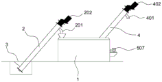
the cleaning auger is transversely arranged in the cleaning pool and comprises a second shell, a second rotating shaft positioned in the second shell, a second propeller blade sleeved outside the second rotating shaft and a second motor connected with the second rotating shaft, one end of the cleaning auger, which is close to the feeding auger, is provided with a second feed inlet communicated with the first discharge outlet, the other end of the cleaning auger is provided with a second discharge outlet, the second rotating shaft is connected with the side wall of the cleaning pool through a bearing, the second motor is fixed on the outer side wall of the cleaning pool, one end of the second rotating shaft penetrates through the side wall of the cleaning pool and is connected with the second motor, and first water leakage holes communicated with the cleaning pool are uniformly distributed on the second shell;
the third motor that the third pivot is connected is established to ejection of compact auger including third casing, third pivot, cover that is located the third casing, third propeller blade and with the third pivot is established outside the third pivot, the ejection of compact auger is close to and washs auger one end and is provided with the third feed inlet that is linked together with the second discharge gate, and the other end is provided with the third discharge gate, the opening direction of third discharge gate and third feed inlet is vertical downwards.
Furthermore, a plurality of second holes that leak are equipped with to the equipartition on the third casing, third casing below cover is equipped with an cowl who extends along casing length direction, cowl is located between third feed inlet and the third discharge gate, the cowl lower extreme extends to in the washing pond.
Furthermore, cowl keeps away from casing one side and is provided with the support of connecting cowl and washing pond, the support includes interconnect's montant and horizontal pole, top and cowl fixed connection at the bottom of the montant, horizontal pole one end and the lateral wall fixed connection who washs the pond, be provided with a plurality of support columns that are used for supporting the casing between cowl and the casing, support column top and casing fixed connection, bottom and cowl fixed connection.
Furthermore, an oil-water separator is arranged on one side of the cleaning pool, the oil-water separator comprises an oil removing tank and an overflow tank arranged on one side of the oil removing tank, a liquid inlet communicated with the cleaning pool is formed in the upper end of the oil removing tank, and an oil discharging port is formed in one side, far away from the liquid inlet, of the oil removing tank; the overflow box is characterized in that an isolation chamber is arranged on the outer side of the overflow box, a water inlet communicated with the interior of the isolation chamber is formed in the bottom of the isolation chamber, an overflow port communicated with the isolation chamber is formed in the upper end of the overflow box, the arrangement height of the overflow port is the same as that of the liquid inlet, and an overflow water outlet is formed in one side of the overflow box.
Furthermore, a partition plate for separating the oil removal tank into a settling chamber and an oil drainage chamber is arranged in the oil removal tank, the height of the partition plate is lower than the height of the liquid inlet and the oil drainage port, the liquid inlet is arranged on one side wall of the settling chamber, the upper end of the settling chamber is communicated with the upper end of the oil drainage chamber, the lower ends of the settling chamber and the oil drainage chamber are provided with liquid drainage ports, and the oil drainage port is arranged on the side wall of the oil drainage chamber.
Further, it is provided with the carrier bar subassembly to wash bottom of the pool portion, it all sets up on the carrier bar subassembly to wash auger and oil water separator, the carrier bar subassembly includes a plurality of and washs pond lateral wall fixed connection's carrier bar, carrier bar subassembly one side is provided with a lead screw parallel with the carrier bar, and the opposite side is provided with the guide bar parallel with the carrier bar, the carrier bar below is provided with the cleaning brush that removes along carrier bar length direction, the cleaning brush top be provided with lead screw threaded connection slide the seat and with guide bar sliding connection's guide holder, it is provided with the drain and is used for the cock board of shutoff drain to wash pond one side, the lead screw is connected with and drives lead screw pivoted driving motor.
Furthermore, the cleaning brush include with slide a fixed connection's roof and with roof bottom fixed connection's riser, the roof all is mutually perpendicular with the carrier bar with the riser, riser one side is provided with the first clearance board with roof fixed connection, the riser bottom is provided with the scraper, first clearance board is kept away from roof one side and is provided with first awl tooth along the direction parallel with the roof, the scraper is located same horizontal plane with the bottom of first awl tooth.
Furthermore, one side, far away from the riser, of the first cleaning plate is provided with a second cleaning plate fixedly connected with the top plate, one side, far away from the top plate, of the second cleaning plate is provided with a second bevel gear, the first bevel gear and the second bevel gear are arranged in a staggered mode, and the bottoms of the first bevel gear, the second bevel gear and the scraper are located on the same horizontal plane.
Furthermore, the bottom of the cleaning pool is provided with a buffer groove which is positioned on one side of the first cleaning plate away from the vertical plate, the buffer groove is sunken towards the direction of the bottom of the cleaning pool, the buffer groove is positioned at the edge of the cleaning pool and is parallel to the cleaning brush, the sewage draining port is arranged at one end of the buffer groove, and the bottom of the buffer groove is obliquely arranged towards the sewage draining port.
Further, it is provided with the heating chamber to wash the pond outward, it has liquid heating medium to lead to in the heating chamber, the heating chamber upper end is provided with the medium entry, and the lower extreme is provided with the medium export, it is provided with the spiral coil pipe that extends along vertical direction to heat the intracavity, the spiral coil pipe upper end is connected with a water pump, the water pump is connected with a tip and extends to the inlet tube in the pond, the spiral coil pipe lower extreme is provided with sends water into the dredging pipe that washs in the pond, be provided with in the washing pond and dredge the drain pipe that the pipe is linked together, the drain pipe top.
The invention has the following beneficial effects: when the garbage is cleaned, firstly, the garbage is fed into the feeding auger from a first feeding hole arranged on the feeding auger, the garbage is lifted by the feeding auger, the garbage is fed into the cleaning auger, a large amount of water in the cleaning tank is sucked into the cleaning auger along with the rotation of a second rotating shaft in the cleaning auger, the water entering the cleaning auger is mixed and collided with the garbage along with the rotation of a second helical blade and the second rotating shaft, the garbage in the cleaning auger is cleaned, the cleaned water leaves the cleaning auger from a first water leakage hole, the garbage reaching a second discharging hole enters the discharging auger from a third feeding hole, the discharging auger conveys the garbage to a third discharging hole, a material receiving hopper is arranged at the third discharging hole to collect the cleaned garbage, the whole process does not need manual operation, and the garbage cleaning can basically realize automation, the operation burden of workers is reduced, meanwhile, the garbage can be salvaged and collected without manual work, the cleaning efficiency of the garbage is greatly improved, and the sewage can be prevented from dripping on the ground outside the cleaning pool, so that the operation environment is clean and sanitary.
Drawings
In order to more clearly illustrate the technical solutions of the embodiments of the present invention, the drawings needed to be used in the embodiments will be briefly described below, it should be understood that the following drawings only illustrate some embodiments of the present invention and therefore should not be considered as limiting the scope, and for those skilled in the art, other related drawings can be obtained according to the drawings without inventive efforts.
FIG. 1 is a schematic view of the overall structure of the present invention;
FIG. 2 is a schematic view of a connection structure of a cleaning auger and a discharging auger;
FIG. 3 is a schematic structural view of a third propeller blade and a third shaft;
FIG. 4 is a schematic diagram of the oil-water separator;
FIG. 5 is a schematic view of the arrangement of the cleaning brush and the lead screw;
FIG. 6 is a side view of the washing brush;
FIG. 7 is a front view of the washing brush;
FIG. 8 is a schematic view of a cleaning tank heating structure;
reference numerals: 1-a cleaning pool, 101-a heating cavity, 102-a spiral coil, 103-a water pump, 104-a water inlet pipe, 105-a dredging pipe, 106-a water outlet pipe, 107-a medium outlet, 108-a medium inlet, 2-a feeding screw conveyor, 201-a first discharge port, 202-a first motor, 3-a feeding hopper, 4-a discharging screw conveyor, 401-a third discharge port, 402-a third motor, 403-a third shell, 404-an arc baffle, 405-a second water leakage hole, 406-a third rotating shaft, 407-a third screw blade, 501-a second shell, 502-a first water leakage hole, 503-a second feed port, 504-a second discharge port, 505-a second rotating shaft, 506-a second screw blade, 507-a second motor, 6-an oil-water separator, 601-a de-oiling box, 602-an overflow box, 603-a liquid inlet, 604-an oil outlet, 605-an overflow port, 606-an isolation chamber, 607-an overflow water outlet, 608-a partition plate, 609-a settling chamber, 610-an oil drainage chamber, 701-a cleaning brush, 702-a screw rod, 703-a guide rod, 704-a sliding seat, 705-a guide seat, 706-a driving motor, 707-a top plate, 708-a vertical plate, 709-a first cleaning plate, 710-a first conical tooth, 711-a second cleaning plate, 712-a second conical tooth, 713-a buffer groove and 8-a carrying rod.
Detailed Description
In order to make the objects, technical solutions and advantages of the embodiments of the present invention clearer, the technical solutions in the embodiments of the present invention will be clearly and completely described below with reference to the drawings in the embodiments of the present invention, and it is obvious that the described embodiments are some, but not all, embodiments of the present invention. The components of embodiments of the present invention generally described and illustrated in the figures herein may be arranged and designed in a wide variety of different configurations.
Thus, the following detailed description of the embodiments of the present invention, presented in the figures, is not intended to limit the scope of the invention, as claimed, but is merely representative of selected embodiments of the invention. All other embodiments, which can be derived by a person skilled in the art from the embodiments given herein without making any creative effort, shall fall within the protection scope of the present invention.
In the description of the present invention, it should be noted that the terms "upper", "lower", "inner", "outer", and the like refer to the orientation or positional relationship based on the orientation or positional relationship shown in the drawings, or the orientation or positional relationship which the product of the present invention is conventionally placed in use, and are used for convenience of description and simplification of description, but do not refer to or imply that the device or element referred to must have a specific orientation, be constructed in a specific orientation, and be operated, and thus should not be construed as limiting the present invention. Furthermore, the terms "first," "second," and the like are used merely to distinguish one description from another, and are not to be construed as indicating or implying relative importance.
In the description of the present invention, it should also be noted that, unless otherwise explicitly specified or limited, the terms "disposed" and "in communication" are to be interpreted broadly, e.g., as either fixed or removable communication, or integrally connected; either mechanically or electrically; they may be connected directly or indirectly through intervening media, or they may be interconnected between two elements. The specific meanings of the above terms in the present invention can be understood in specific cases to those skilled in the art.
Examples
Referring to fig. 1 to 8, the present embodiment provides a garbage cleaning apparatus, which includes a cleaning tank 1, a sewage discharge pipe arranged at a lower end of the cleaning tank 1, and a feeding auger 2, a cleaning auger and a discharging auger 4 connected in sequence;
wherein, the feeding auger 2 is used for lifting the garbage to more laborsavingly feed the garbage into the cleaning auger, the feeding auger 2 comprises a first shell, a first rotating shaft positioned in the first shell, a first screw blade sheathed outside the first rotating shaft and a first motor 202 connected with the first rotating shaft, the feeding auger 2 can be directly fixed on the ground by arranging a plurality of brackets to support the feeding auger, one end of the feeding auger 2, which is far away from the cleaning auger, is provided with a first feeding port, the other end of the feeding auger is provided with a first discharging port 201, the opening direction of the first feeding port is vertical upwards, the opening direction of the first discharging port 201 is vertical downwards, the height of the first discharging port 201 is higher than that of the first feeding port, in the actual use process, a feeding hopper 3 can be arranged underground, the feeding end of the feeding auger 2 is fixed in the hopper 3, and the opening of the first feeding port is positioned under the ground or slightly higher than the ground, when making rubbish wash, treat that abluent rubbish drops into first feed inlet very laborsavingly, need not to carry out the lifting to rubbish and can pour rubbish into in the first feed inlet smoothly.
The cleaning auger is transversely arranged in the cleaning pool 1, the cleaning auger comprises a second shell 501, a second rotating shaft 505 positioned in the second shell 501, a second propeller blade 506 sleeved outside the second rotating shaft 505 and a second motor 507 connected with the second rotating shaft 505, one end of the cleaning auger close to the feeding auger 2 is provided with a second feeding hole 503 communicated with the first discharging hole 201, the other end is provided with a second discharging hole 504, the second rotating shaft 505 is connected with the side wall of the cleaning pool 1 through a bearing, the second motor 507 is fixed on the outer side wall of the cleaning pool 1, one end of the second rotating shaft 505 penetrates through the side wall of the cleaning pool 1 and is connected with the second motor 507, the second shell 501 is uniformly distributed with first water leakage holes 502 communicated with the cleaning pool 1, when in use, garbage is lifted by the feeding auger 2 and then enters the second feeding hole 503 from the first discharging hole 201, the second motor 507 drives the second rotating shaft 505 to rotate, thereby driving the garbage to move towards the direction of the second discharging hole 504, meanwhile, water in the cleaning pool 1 enters the cleaning auger from the first water leakage hole 502 under the action of suction force, is mixed and collided with garbage in the cleaning auger, and cleans the garbage in the cleaning auger.
The discharging auger 4 comprises a third shell 403, a third rotating shaft 406 positioned in the third shell 403, a third propeller blade 407 sleeved outside the third rotating shaft 406 and a third motor 402 connected with the third rotating shaft 406, wherein the first propeller blade, the second bolt blade and the third propeller blade 407 have the same structure, the first rotating shaft, the second rotating shaft 505 and the third rotating shaft 406 have the same structure, the first motor 202, the second motor 507 and the third motor 402 can be motors which are convenient to adjust and control such as a stepping motor and a servo motor, and the first motor 202, the second motor 507 and the third motor 402 can be connected with a speed reducer so as to adjust the garbage transmission speed; the third feed inlet that is linked together with second discharge gate 504 is provided with near washing auger one end to ejection of compact auger 4, the other end is provided with third discharge gate 401, the opening direction of third discharge gate 401 and third feed inlet is vertical downwards, the height that highly is higher than the third feed inlet of third discharge gate 401, third feed inlet and second discharge gate 504 butt joint, the rubbish that leaves from washing the auger gets into ejection of compact auger 4 in by the third feed inlet, promote and carry rubbish to third discharge gate 401 department by ejection of compact auger 4, place a hopper below third discharge gate 401, alright collect the rubbish of ejection of compact auger 4 department of transport, the trouble of artifical salvage rubbish is removed from, and rubbish also can not scatter in wasing pond 1, make the collection of rubbish more comprehensive. And contain more moisture in the rubbish of the ejection of compact auger 4 of going into after the washing, in order to reduce the volume of the water that contains in the rubbish, this implementation is provided with a plurality of second holes 405 that leaks on third casing 403, and the cover is equipped with an cowl 404 that extends along casing length direction below third casing 403, cowl 404 is used for collecting the water that second hole 405 that leaks flows, avoid it to drip subaerial, and cowl 404 is located between third feed inlet and third discharge gate 401, cowl 404 lower extreme extends to in the washing pond 1, in order to send the water that cowl 404 collected back to washing pond 1, can the water economy resource, can make the ground of workshop keep dry clean again. Meanwhile, in order to facilitate the fixation of the arc-shaped baffle 404 and the discharging auger 4, a bracket for connecting the arc-shaped baffle 404 and the cleaning pool 1 can be arranged on one side of the arc-shaped baffle 404 away from the shell, the bracket comprises a vertical rod and a horizontal rod which are connected with each other, the top of the bottom of the vertical rod is fixedly connected with the arc-shaped baffle 404, one end of the horizontal rod is fixedly connected with the side wall of the cleaning pool 1, wherein, 2 or more groups of brackets can be arranged in parallel to effectively support the arc baffle 404, and a plurality of support columns for supporting the shell can be arranged between the arc-shaped baffle 404 and the shell, the top of each support column is fixedly connected with the shell, the bottom of each support column is fixedly connected with the arc-shaped baffle 404, the upper end of the discharging auger 4 is supported by the arc-shaped baffle 404, the lower end of the discharging auger 4 is supported by the cleaning pool 1, and specifically, a plurality of supports are arranged to connect the lower end of the discharging auger 4 with the cleaning pool 1.
Meanwhile, in order to separate oil and water in the cleaning pool 1 in the cleaning process and discharge grease out of the cleaning pool 1, and improve the cleaning effect of garbage, an oil-water separator 6 can be arranged on one side of the cleaning pool 1, the oil-water separator 6 comprises an oil removing tank 601 and an overflow tank 602 arranged on one side of the oil removing tank 601, wherein the upper end of the oil removing tank 601 is provided with a liquid inlet 603 communicated with the cleaning pool 1, the grease floats on the water surface because the density of the grease is less than that of the water, a grease layer on the upper end of the cleaning pool 1 enters the oil removing tank 601 from the liquid inlet 603, the water on the lower end does not enter the oil removing tank 601, the cleaning of the garbage is not influenced, the grease content in the cleaning pool 1 can be reduced, the cleaned garbage is prevented from being stained with the grease from the cleaning pool 1, the cleaning effect is improved when the garbage is more dirty, and a drainage port 604 is arranged on one side of the oil removing tank 601 far away from the liquid, the oil-water separator is used for discharging oil in the oil removing tank 601, so that real-time oil-water separation and real-time oil discharge are realized;
wherein, the overflow tank 602 is used for storing or discharging part of the water in the cleaning pool 1 when the liquid level in the cleaning pool 1 is too high, an isolation chamber 606 is arranged at the outer side of the overflow tank 602, a water inlet communicated with the inside of the isolation chamber 606 is arranged at the bottom of the isolation chamber 606, the position of the water inlet is lower than that of the liquid inlet 603, an overflow port 605 communicated with the isolation chamber 606 is arranged at the upper end of the overflow tank 602, the setting height of the overflow port 605 is the same as that of the liquid inlet 603, when the water in the cleaning pool 1 is more, the water at the lower layer enters the isolation chamber 606 from the water inlet and enters the overflow tank 602 from the overflow port 605, thereby assisting the oil removal tank 601 to carry out oil-water separation, reducing the amount of the water entering the oil removal tank 601, improving the speed of the oil-water separation, meanwhile, an overflow water outlet 607 is arranged at one side of the overflow tank 602, and the water, a valve may be provided at the overflow outlet 607 to allow water to be drawn out when a certain amount of water is present in the overflow tank 602. Wherein, the upper surface of deoiling case 601 and overflow case 602 can with wash the upper surface parallel and level of pond 1, and the position of inlet 603 and overflow mouth 605's upper surface is less than the position of wasing pond 1 upper surface a little, owing to when wasing rubbish, generally can be equipped with more water in the washing pond 1, carry out such setting to the height of deoiling case 601 and overflow case 602 etc. to can play fabulous overflow and oil extraction effect.
In order to further improve the oil-water separation effect, a partition 608 which divides the oil removal tank 601 into a settling chamber 609 and an oil discharge chamber 610 is arranged in the oil removal tank 601, the height of the partition 608 is lower than the arrangement heights of the liquid inlet 603 and the oil discharge port 604, wherein the liquid inlet 603 is arranged on one side wall of the settling chamber 609, the upper end of the settling chamber 609 is communicated with the upper end of the oil discharge chamber 610, the lower ends of the settling chamber 609 and the oil discharge chamber 610 are respectively provided with a liquid discharge port, the oil discharge port 604 is arranged on the side wall of the oil discharge chamber 610, liquid enters the settling chamber 609 after entering from the liquid inlet 603, the settling chamber 609 is buffered by the settling chamber 609, the grease enters the oil discharge chamber 610 from the upper part of the partition 608, the water can be further settled, the grease leaves the oil removal tank 601 from the oil discharge port 604, when the cleaning tank 1 needs to replace the water, the residual liquid in the settling chamber 609 and the oil discharge chamber 610 can be discharged from the liquid discharge port, therefore, the drain port needs to be disposed near the bottom of the settling chamber 609 and the oil discharge chamber 610, and the drain port can be provided with a valve to control the opening and closing of the drain port.
The household garbage usually contains more small particulate matters, such as dust, rice grains, small particulate seasonings in dishes and the like, the small particulate matters enter the cleaning tank 1 from the first water leakage holes 502 and are deposited at the bottom of the cleaning tank 1, and if the small particulate matters are not treated, organic matters contained in the small particulate matters can give off odor and breed bacteria to adversely affect the garbage cleaning, so that the bottom of the cleaning tank 1 is provided with the bearing rod assembly, and the cleaning auger and the oil-water separator 6 are arranged on the bearing rod assembly, thereby not only effectively supporting the garbage, but also preventing the garbage from contacting with the small solid particles deposited at the bottom of the cleaning tank 1 during the garbage cleaning, and improving the cleaning effect of the garbage; the bearing rod 8 assembly comprises a plurality of bearing rods 8 fixedly connected with the side wall of the cleaning pool 1, one side of each bearing rod assembly is provided with a screw rod 702 parallel to the bearing rods 8, the other side of each bearing rod assembly is provided with a guide rod 703 parallel to the bearing rods 8, the screw rods 702 are connected with a driving motor 706 driving the screw rods 702 to rotate, the driving motors 706 can be motors capable of controlling forward and reverse rotation such as stepping motors and servo motors, of course, the screw rods 702 can be set to be reciprocating screw rods 702 optionally, the motors can be operated by unidirectional rotation, and the arrangement positions of the screw rods 702 can be lower than the bearing rods 8 so as to avoid influence on the installation of other parts in the cleaning pool 1; a cleaning brush 701 moving along the length direction of the carrier bar 8 is arranged below the carrier bar 8, a sliding seat 704 in threaded connection with the lead screw 702 and a guide seat 705 in sliding connection with the guide rod 703 are arranged at the top of the cleaning brush 701, when the lead screw 702 rotates, the sliding seat 704 moves along the length direction of the carrier bar 8, the moving direction is determined by the rotating direction of the lead screw 702, when the sliding seat 704 moves, the cleaning brush 701 moves along with the sliding seat 704, the guide rod 703 can limit the position of the cleaning brush 701, so that the cleaning brush 701 moves along with the sliding seat 704 without tilting, a sewage outlet and a plug plate for plugging the sewage outlet are arranged at one side of the cleaning pool 1, the sewage outlet is used for discharging small solid particles sent by the cleaning brush 701 out of the cleaning pool 1, the plug plate is used for controlling the opening and closing of the sewage outlet, and a better sealing effect can be achieved during cleaning, and when in pollution discharge, the valve is opened for discharging small solid particles. Wherein the water outlet is arranged above the sewage draining exit, preferably above the bearing rod 8.
In one embodiment of the washing brush 701, the washing brush 701 includes a top plate 707 fixedly connected to the sliding seat 704 and a vertical plate 708 fixedly connected to the bottom of the top plate 707, both the top plate 707 and the vertical plate 708 are perpendicular to the support rod 8, namely, the vertical plate 708 is parallel to the side wall of the cleaning tank 1, the vertical plate 708 is parallel to the bottom plate of the cleaning tank 1, one side of the vertical plate 708 is provided with a first cleaning plate 709 fixedly connected with the top plate 707, one side of the first cleaning plate 709 far away from the top plate 707 is provided with a first bevel gear 710 along the direction parallel to the top plate 707, and the first cleaning plate 709 is positioned at the side close to the sewage draining outlet, when cleaning, the first bevel gear 710 scrapes loose the solid particles deposited at the bottom of the cleaning pool 1, and the vertical plate 708 which is next to the vertical plate pushes the small solid particles which are scraped loose by the first bevel tooth 710 to reach the sewage draining port and leave the cleaning pool 1, so that the cleaning of the cleaning pool 1 is realized. Meanwhile, in order to further enhance the cleaning capability of the cleaning brush 701 on the small solid particles, a second cleaning plate 711 fixedly connected with the top plate 707 may be disposed on one side of the first cleaning plate 709 away from the vertical plate 708, a second taper tooth 712 is disposed on one side of the second cleaning plate 711 away from the top plate 707, the first taper tooth 710 and the second taper tooth 712 are disposed in a staggered manner, the small solid particles at the bottom of the cleaning pool 1 are scraped comprehensively by the first taper tooth 710 and the second taper tooth 712 which are disposed in a staggered manner, and then the small solid particles are pushed to be cleaned by the vertical plate 708, and a scraper may be disposed at the bottom of the vertical plate 708, the scraper is located on the same horizontal plane as the bottoms of the first taper tooth 710 and the second taper tooth 712, and the scraper may further scrape the small solid particles at the bottom of the cleaning pool 1, thereby further enhancing the sewage discharge capability of the.
And in order to make the cleaning brush 701 promote the solid tiny particle that washs pond 1 one side discharge outside washing pond 1 comparatively conveniently, can set up a buffer slot that is located first cleaning plate 709 and keeps away from riser 708 one side in washing pond 1 bottom, the buffer slot is located washing pond 1 edge and is parallel with cleaning brush 701, and the buffer slot caves in towards the direction of washing pond 1 bottom, the drain sets up in buffer slot one end, the buffer slot bottom sets up towards the slope of the direction of drain, in the time of the use, cleaning brush 701 promotes the solid tiny particle and gets into in the buffer slot, and the buffer slot slope sets up, still contain part of water in the solid tiny particle after scraping the pine, make it have better mobility, namely it can slide gradually to drain along the buffer slot bottom, and leave cleaning pond 1 from the drain.
Meanwhile, in order to effectively heat and preserve heat of water in the cleaning pool 1 and improve the oil removing effect of the cleaning pool 1, a heating device of the cleaning pool 1 is improved, wherein a heating cavity 101 is arranged outside the cleaning pool 1, a liquid heating medium is filled in the heating cavity 101, the liquid heating medium can be heat conduction oil or water for conventional heating, a medium inlet 108 is arranged at the upper end of the heating cavity 101, a medium outlet 107 is arranged at the lower end of the heating cavity 101, the medium inlet 108 is used for introducing the heating medium, the medium outlet 107 is used for discharging the heating medium subjected to heat exchange in the heating cavity 101, and the heating medium is sent into an external heating device for heating and then sent into the heating cavity 101 again to heat or preserve heat of the water in the cleaning pool 1; the heating cavity 101 is internally provided with a spiral coil 102 extending along the vertical direction, the spiral coil is made of a material with good heat conduction effect, so that the heat exchange effect inside and outside the spiral coil 102 is good, the upper end of the spiral coil 102 is connected with a water pump 103, the water pump 103 is connected with a water inlet pipe 104, one end of the water inlet pipe extends into the water tank, the water inlet pipe 104 is fixed on the side wall of the cleaning tank 11, namely the water inlet pipe 104 is positioned at the edge of the cleaning tank 1, the influence of the water inlet pipe 104 on garbage cleaning is avoided, the water inlet pipe 104 can be connected with a pore plate fixedly connected with the cleaning tank 1, the water pump 103 sends water at the upper part of the cleaning tank 1 into the spiral coil 102 through the water inlet pipe 104, the water in the spiral coil 102 exchanges heat with a heating medium in the heating cavity 101 to heat the water, and the spiral coil 102 can meander for a long length due, the lower end of the spiral coil 102 is provided with a dredging pipe for sending water into the cleaning pool 1, the cleaning pool 1 is internally provided with a drain pipe communicated with the dredging pipe, the bottom of the drain pipe is fixedly connected with the bottom of the cleaning pool 1, the top of the drain pipe is provided with a water outlet, the water in the spiral coil 102 after heat exchange with a heating medium passes through the dredging pipe and the drain pipe and enters the lower end of the cleaning pool 1 from the water outlet, wherein, the water outlet can be arranged towards the middle part of the cleaning pool 1, so that the water discharged from the water outlet flows towards the middle part of the cleaning pool 1, the water temperature in the cleaning pool 1 is more uniform, meanwhile, the top of the drain pipe can be bent, namely, the water outlet is arranged towards the bottom of the cleaning pool 1, so that the hot water discharged from the spiral coil 102 can generate certain impact force on the bottom of the cleaning pool, but also the water is subject to the rebound force at the bottom of the cleaning pool 11, the flowing speed of the water in the cleaning pool 1 is accelerated, and the temperature of the water in the cleaning pool 1 is more uniform. In addition, in order to prevent the small solid particles in the cleaning tank 1 from entering the water discharge pipe and the water inlet pipe 104, a filter screen may be provided at the mouth and the water discharge port of the water inlet pipe 104 to prevent the water pump 103 and the spiral coil 102 from being clogged.
In addition, in order to further improve the heat transfer effect between water and a heating medium in the spiral coil 102, at least one coil support for supporting the spiral coil 102 is arranged in the heating chamber 101, the coil supports are uniformly distributed in the heating chamber 101 to effectively support the spiral coil 102, each coil support comprises a vertical orifice plate 106 and a plurality of transverse fixing plates 105 for fixing the vertical orifice plate 106 on the wall of the heating chamber 101, a plurality of mounting holes are uniformly distributed on the vertical orifice plate 106 along the vertical direction, the mounting holes on the vertical orifice plates 106 are matched with each other, the spiral coil 102 sequentially passes through the mounting holes and is supported by the mounting holes, one end of each fixing plate 105 is welded with the vertical orifice plate 106, the other end of each fixing plate 105 is welded with the wall of the heating chamber 101, wherein the fixing plates 105 can be connected with the inner wall of the heating chamber 101 and the outer wall of the heating chamber 101, and the arrangement mode, so that the heating medium and the water in the spiral coil 102 can perform more sufficient heat exchange, and the heating effect of the water is improved.
The above description is only a preferred embodiment of the present invention, and not intended to limit the present invention, the scope of the present invention is defined by the appended claims, and all structural changes that can be made by using the contents of the description and the drawings of the present invention are intended to be embraced therein.
Claims (10)
1. A garbage cleaning device comprises a cleaning pool (1) and a sewage calandria arranged at the lower end of the cleaning pool (1), and is characterized by further comprising a feeding auger (2), a cleaning auger and a discharging auger (4) which are sequentially connected;
the feeding auger (2) comprises a first shell, a first rotating shaft positioned in the first shell, a first propeller blade sleeved outside the first rotating shaft and a first motor (202) connected with the first rotating shaft, wherein one end of the feeding auger (2) far away from the cleaning auger is provided with a first feeding hole, the other end of the feeding auger is provided with a first discharging hole (201), the opening direction of the first feeding hole is vertically upward, and the opening direction of the first discharging hole (201) is vertically downward;
the cleaning packing auger is transversely arranged in the cleaning pool (1), the cleaning packing auger comprises a second shell (501), a second rotating shaft (505) positioned in the second shell (501), a second propeller blade (506) sleeved outside the second rotating shaft (505) and a second motor (507) connected with the second rotating shaft (505), one end of the cleaning packing auger, which is close to the feeding packing auger (2), is provided with a second feeding hole (503) which is communicated with the first discharging hole (201), the other end is provided with a second discharging hole (504), the second rotating shaft (505) is connected with the side wall of the cleaning pool (1) through a bearing, the second motor (507) is fixed on the outer side wall of the cleaning pool (1), one end of the second rotating shaft (505) penetrates through the side wall of the cleaning pool (1) and is connected with the second motor (507), first water leakage holes (502) communicated with the cleaning pool (1) are uniformly distributed on the second shell (501);
the third motor (402) that third pivot (406), cover that ejection of compact auger (4) include third casing (403), are located third casing (403) and establish third propeller blade (407) outside third pivot (406) and be connected with third pivot (406), ejection of compact auger (4) are close to wash auger one end and are provided with the third feed inlet that is linked together with second discharge gate (504), and the other end is provided with third discharge gate (401), the opening direction of third discharge gate (401) and third feed inlet is vertical downwards.
2. The garbage cleaning device according to claim 1, wherein a plurality of second water leakage holes (405) are uniformly distributed on the third shell (403), an arc-shaped baffle (404) extending along the length direction of the shell is sleeved below the third shell (403), the arc-shaped baffle (404) is located between the third feeding port and the third discharging port (401), and the lower end of the arc-shaped baffle (404) extends into the cleaning tank (1).
3. A garbage cleaning device according to claim 2, characterized in that a support for connecting the arc-shaped baffle (404) with the cleaning tank (1) is arranged on the side of the arc-shaped baffle (404) away from the housing, the support comprises mutually connected vertical bars and horizontal bars, the top of the bottom of each vertical bar is fixedly connected with the arc-shaped baffle (404), one end of each horizontal bar is fixedly connected with the side wall of the cleaning tank (1), a plurality of support columns for supporting the third housing (403) are arranged between the arc-shaped baffle (404) and the housing, the top of each support column is fixedly connected with the third housing (403), and the bottom of each support column is fixedly connected with the arc-shaped baffle (404).
4. The garbage cleaning device according to claim 1, wherein an oil-water separator (6) is arranged at one side of the cleaning pool (1), the oil-water separator (6) comprises an oil removing tank (601) and an overflow tank (602) arranged at one side of the oil removing tank (601), a liquid inlet (603) communicated with the cleaning pool (1) is arranged at the upper end of the oil removing tank (601), and an oil discharging port (604) is arranged at one side of the oil removing tank (601) far away from the liquid inlet (603); an isolation chamber (606) is arranged on the outer side of the overflow tank (602), a water inlet communicated with the interior of the isolation chamber (606) is formed in the bottom of the isolation chamber (606), an overflow port (605) communicated with the isolation chamber (606) is formed in the upper end of the overflow tank (602), the setting height of the overflow port (605) is the same as that of the liquid inlet (603), and an overflow water outlet (607) is formed in one side of the overflow tank (602).
5. A garbage cleaning device according to claim 4, characterized in that a partition (608) is provided in the oil removing tank (601) to divide the oil removing tank (601) into a settling chamber (609) and an oil discharging chamber (610), the height of the partition (608) is lower than the height of the liquid inlet (603) and the oil discharging port (604), the liquid inlet (603) is provided on one side wall of the settling chamber (609), the upper end of the settling chamber (609) is communicated with the upper end of the oil discharging chamber (610), the lower ends of the settling chamber (609) and the oil discharging chamber (610) are provided with liquid discharging ports, and the oil discharging port (604) is provided on the side wall of the oil discharging chamber (610).
6. The garbage cleaning device according to claim 4, wherein a bearing rod assembly is arranged at the bottom of the cleaning pool (1), the cleaning packing auger and the oil-water separator (6) are arranged on the bearing rod assembly, the bearing rod assembly comprises a plurality of bearing rods (8) fixedly connected with the side wall of the cleaning pool (1), one side of the bearing rod assembly is provided with a screw rod (702) parallel to the bearing rod (8), the other side of the bearing rod assembly is provided with a guide rod (703) parallel to the bearing rod (8), a cleaning brush (701) moving along the length direction of the bearing rod (8) is arranged below the bearing rod (8), the top of the cleaning brush (701) is provided with a sliding seat (704) in threaded connection with the screw rod (702) and a guide seat (703) in sliding connection with the guide rod (8), one side of the cleaning pool (1) is provided with a drain outlet and a plug plate for plugging the drain outlet, the screw rod (702) is connected with a driving motor (706) which drives the screw rod (702) to rotate.
7. A garbage cleaning device according to claim 6, characterized in that the cleaning brush (701) comprises a top plate (707) fixedly connected with the sliding seat (704) and a vertical plate (708) fixedly connected with the bottom of the top plate (707), the top plate (707) and the vertical plate (708) are both perpendicular to the carrying rod (8), one side of the vertical plate (708) is provided with a first cleaning plate (709) fixedly connected with the top plate (707), the bottom of the vertical plate (708) is provided with a scraper, one side of the first cleaning plate (709) far away from the top plate (707) is provided with a first bevel gear (710) along the direction parallel to the top plate (707), and the scraper and the bottom of the first bevel gear (710) are located on the same horizontal plane.
8. The garbage cleaning device according to claim 7, wherein a second cleaning plate (711) fixedly connected with the top plate (707) is arranged on one side of the first cleaning plate (709) far away from the vertical plate (708), a second taper tooth (712) is arranged on one side of the second cleaning plate (711) far away from the top plate (707), the first taper tooth (710) and the second taper tooth (712) are arranged in a staggered manner, and bottoms of the first taper tooth (710), the second taper tooth (712) and the scraper are located on the same horizontal plane.
9. A garbage cleaning device according to claim 6, characterized in that the bottom of the cleaning tank (1) is provided with a buffer groove (713) at the side of the first cleaning plate (709) far away from the vertical plate (708), the buffer groove (713) is concave towards the bottom of the cleaning tank (1), the buffer groove (713) is at the edge of the cleaning tank (1) and is parallel to the cleaning brush (701), the sewage draining outlet is arranged at one end of the buffer groove (713), and the bottom of the buffer groove (713) is inclined towards the sewage draining outlet.
10. Waste cleaning device according to any of claims 1-9, a heating cavity (101) is arranged outside the cleaning pool (1), a liquid heating medium is filled in the heating cavity (101), the upper end of the heating cavity (101) is provided with a medium inlet (108), the lower end is provided with a medium outlet (107), a spiral coil pipe (102) extending along the vertical direction is arranged in the heating cavity (101), the upper end of the spiral coil (102) is connected with a water pump (103), the water pump (103) is connected with a water inlet pipe (104) with one end extending into the water tank, the lower end of the spiral coil (102) is provided with a dredging pipe (105) for sending water into the cleaning pool (1), a drain pipe (106) communicated with the dredging pipe (105) is arranged in the cleaning pool (1), and a water outlet is formed in the top of the drain pipe (106).
Priority Applications (1)
| Application Number | Priority Date | Filing Date | Title |
|---|---|---|---|
| CN201911014112.1A CN110756500A (en) | 2019-10-23 | 2019-10-23 | Garbage cleaning device |
Applications Claiming Priority (1)
| Application Number | Priority Date | Filing Date | Title |
|---|---|---|---|
| CN201911014112.1A CN110756500A (en) | 2019-10-23 | 2019-10-23 | Garbage cleaning device |
Publications (1)
| Publication Number | Publication Date |
|---|---|
| CN110756500A true CN110756500A (en) | 2020-02-07 |
Family
ID=69333312
Family Applications (1)
| Application Number | Title | Priority Date | Filing Date |
|---|---|---|---|
| CN201911014112.1A Pending CN110756500A (en) | 2019-10-23 | 2019-10-23 | Garbage cleaning device |
Country Status (1)
| Country | Link |
|---|---|
| CN (1) | CN110756500A (en) |
Cited By (1)
| Publication number | Priority date | Publication date | Assignee | Title |
|---|---|---|---|---|
| CN113477642A (en) * | 2021-06-05 | 2021-10-08 | 阳泉鑫丰溢科技有限公司 | Waste zinc-containing material packaging bag recycling and cleaning device |
Citations (5)
| Publication number | Priority date | Publication date | Assignee | Title |
|---|---|---|---|---|
| JP2005334839A (en) * | 2004-05-31 | 2005-12-08 | Okawa Kensetsu Kogyo:Kk | Oil-water separator |
| CN102614684A (en) * | 2012-04-19 | 2012-08-01 | 中水北方勘测设计研究有限责任公司 | Oil-water separation device for leakage drainage system in hydropower station |
| CN105478409A (en) * | 2014-10-09 | 2016-04-13 | 枝江市宏安化纤有限责任公司 | Bottle cap cleaning device |
| CN208879286U (en) * | 2018-07-12 | 2019-05-21 | 杭州磐腾机械有限公司 | A kind of recycled plastic precleaning machine |
| CN210995543U (en) * | 2019-10-23 | 2020-07-14 | 四川天森农牧设备制造有限公司 | Garbage cleaning device |
-
2019
- 2019-10-23 CN CN201911014112.1A patent/CN110756500A/en active Pending
Patent Citations (5)
| Publication number | Priority date | Publication date | Assignee | Title |
|---|---|---|---|---|
| JP2005334839A (en) * | 2004-05-31 | 2005-12-08 | Okawa Kensetsu Kogyo:Kk | Oil-water separator |
| CN102614684A (en) * | 2012-04-19 | 2012-08-01 | 中水北方勘测设计研究有限责任公司 | Oil-water separation device for leakage drainage system in hydropower station |
| CN105478409A (en) * | 2014-10-09 | 2016-04-13 | 枝江市宏安化纤有限责任公司 | Bottle cap cleaning device |
| CN208879286U (en) * | 2018-07-12 | 2019-05-21 | 杭州磐腾机械有限公司 | A kind of recycled plastic precleaning machine |
| CN210995543U (en) * | 2019-10-23 | 2020-07-14 | 四川天森农牧设备制造有限公司 | Garbage cleaning device |
Cited By (2)
| Publication number | Priority date | Publication date | Assignee | Title |
|---|---|---|---|---|
| CN113477642A (en) * | 2021-06-05 | 2021-10-08 | 阳泉鑫丰溢科技有限公司 | Waste zinc-containing material packaging bag recycling and cleaning device |
| CN113477642B (en) * | 2021-06-05 | 2022-06-14 | 阳泉鑫丰溢科技有限公司 | Waste zinc-containing material packaging bag recycling and cleaning device |
Similar Documents
| Publication | Publication Date | Title |
|---|---|---|
| CN112978952A (en) | Municipal administration sewage treatment system | |
| CN210995543U (en) | Garbage cleaning device | |
| KR101974195B1 (en) | Oil circulating type frying apparatus | |
| CN110756500A (en) | Garbage cleaning device | |
| CN219636964U (en) | Oil-water separator for kitchen sewage treatment | |
| CN116002785A (en) | Urban domestic wastewater treatment device | |
| CN214693603U (en) | Flocculation stirring mud scraper | |
| CN113005465B (en) | Acid pickling module for galvanizing line barrel plating process | |
| CN214780812U (en) | Aquaculture tail water treatment device with sediment collection function | |
| CN214270413U (en) | Culture seawater circulating water treatment device | |
| CN211536656U (en) | Blowdown equipment for wire drawing machine | |
| CN210012720U (en) | Septic tank convenient to clearance | |
| CN208162205U (en) | Oil pipe cleaning device | |
| CN206809868U (en) | A kind of overflow-type sand-water separating device | |
| CN110665262A (en) | Sewage treatment clean concentration tank | |
| CN217709065U (en) | Oil-water separator | |
| CN219701322U (en) | Oil-water separator for kitchen waste treatment | |
| CN216614275U (en) | Reclaimed water recycling equipment | |
| CN219376397U (en) | Aluminum product oxidation electrolysis waste liquid treatment equipment | |
| CN216946478U (en) | Oil-water separator with residue scraping assembly | |
| CN218025752U (en) | Sealed oil-water separator | |
| CN215310780U (en) | Quick precipitation equipment of water conservancy construction | |
| CN220223900U (en) | Advanced treatment device | |
| CN216392978U (en) | Vegetable cleaning machine discharging device convenient for removing residues | |
| CN211768538U (en) | Conveyor belt drainage device |
Legal Events
| Date | Code | Title | Description |
|---|---|---|---|
| PB01 | Publication | ||
| PB01 | Publication | ||
| SE01 | Entry into force of request for substantive examination | ||
| SE01 | Entry into force of request for substantive examination |