CN110752680A - Hydroelectric turbine, anchoring structure and associated assembly method - Google Patents
Hydroelectric turbine, anchoring structure and associated assembly method Download PDFInfo
- Publication number
- CN110752680A CN110752680A CN201911130660.0A CN201911130660A CN110752680A CN 110752680 A CN110752680 A CN 110752680A CN 201911130660 A CN201911130660 A CN 201911130660A CN 110752680 A CN110752680 A CN 110752680A
- Authority
- CN
- China
- Prior art keywords
- rotor
- stator
- support
- hydroelectric turbine
- turbine system
- Prior art date
- Legal status (The legal status is an assumption and is not a legal conclusion. Google has not performed a legal analysis and makes no representation as to the accuracy of the status listed.)
- Pending
Links
- 238000004873 anchoring Methods 0.000 title claims description 36
- 238000000034 method Methods 0.000 title claims description 25
- 230000007246 mechanism Effects 0.000 claims abstract description 11
- 239000000463 material Substances 0.000 claims description 56
- 210000002105 tongue Anatomy 0.000 claims description 32
- 238000004519 manufacturing process Methods 0.000 claims description 30
- XLYOFNOQVPJJNP-UHFFFAOYSA-N water Substances O XLYOFNOQVPJJNP-UHFFFAOYSA-N 0.000 claims description 28
- 239000002131 composite material Substances 0.000 claims description 27
- 238000009434 installation Methods 0.000 claims description 21
- 229920000049 Carbon (fiber) Polymers 0.000 claims description 12
- 239000004917 carbon fiber Substances 0.000 claims description 12
- VNWKTOKETHGBQD-UHFFFAOYSA-N methane Chemical compound C VNWKTOKETHGBQD-UHFFFAOYSA-N 0.000 claims description 11
- 230000033001 locomotion Effects 0.000 claims description 5
- 238000005266 casting Methods 0.000 claims description 3
- 239000007788 liquid Substances 0.000 claims description 3
- 230000004323 axial length Effects 0.000 claims 1
- 238000010030 laminating Methods 0.000 claims 1
- 239000012530 fluid Substances 0.000 description 45
- 238000011144 upstream manufacturing Methods 0.000 description 18
- 230000005611 electricity Effects 0.000 description 10
- 210000002683 foot Anatomy 0.000 description 9
- 238000005339 levitation Methods 0.000 description 9
- 230000008901 benefit Effects 0.000 description 8
- 239000004593 Epoxy Substances 0.000 description 7
- 239000002023 wood Substances 0.000 description 6
- 239000000919 ceramic Substances 0.000 description 5
- 239000013535 sea water Substances 0.000 description 5
- 238000009749 continuous casting Methods 0.000 description 4
- 230000000694 effects Effects 0.000 description 4
- 239000002184 metal Substances 0.000 description 4
- 230000001846 repelling effect Effects 0.000 description 4
- 238000003860 storage Methods 0.000 description 4
- 241000190019 Guaiacum Species 0.000 description 3
- 235000004440 Guaiacum sanctum Nutrition 0.000 description 3
- FAPWRFPIFSIZLT-UHFFFAOYSA-M Sodium chloride Chemical compound [Na+].[Cl-] FAPWRFPIFSIZLT-UHFFFAOYSA-M 0.000 description 3
- 230000005540 biological transmission Effects 0.000 description 3
- 230000006835 compression Effects 0.000 description 3
- 238000007906 compression Methods 0.000 description 3
- 238000003780 insertion Methods 0.000 description 3
- 230000037431 insertion Effects 0.000 description 3
- 238000012423 maintenance Methods 0.000 description 3
- 239000011780 sodium chloride Substances 0.000 description 3
- 238000004804 winding Methods 0.000 description 3
- 229920000271 Kevlar® Polymers 0.000 description 2
- 239000000853 adhesive Substances 0.000 description 2
- 230000001070 adhesive effect Effects 0.000 description 2
- 238000005452 bending Methods 0.000 description 2
- 239000004020 conductor Substances 0.000 description 2
- 230000008878 coupling Effects 0.000 description 2
- 238000010168 coupling process Methods 0.000 description 2
- 238000005859 coupling reaction Methods 0.000 description 2
- 230000003993 interaction Effects 0.000 description 2
- 239000004761 kevlar Substances 0.000 description 2
- 238000012986 modification Methods 0.000 description 2
- 230000004048 modification Effects 0.000 description 2
- 229920000642 polymer Polymers 0.000 description 2
- 238000010248 power generation Methods 0.000 description 2
- 230000008569 process Effects 0.000 description 2
- 239000007921 spray Substances 0.000 description 2
- 239000000758 substrate Substances 0.000 description 2
- OKTJSMMVPCPJKN-UHFFFAOYSA-N Carbon Chemical compound [C] OKTJSMMVPCPJKN-UHFFFAOYSA-N 0.000 description 1
- UFHFLCQGNIYNRP-UHFFFAOYSA-N Hydrogen Chemical compound [H][H] UFHFLCQGNIYNRP-UHFFFAOYSA-N 0.000 description 1
- 229910000831 Steel Inorganic materials 0.000 description 1
- 229910045601 alloy Inorganic materials 0.000 description 1
- 239000000956 alloy Substances 0.000 description 1
- 230000015572 biosynthetic process Effects 0.000 description 1
- 229910052799 carbon Inorganic materials 0.000 description 1
- 239000004568 cement Substances 0.000 description 1
- 238000006243 chemical reaction Methods 0.000 description 1
- 239000003245 coal Substances 0.000 description 1
- 238000010276 construction Methods 0.000 description 1
- 229910003460 diamond Inorganic materials 0.000 description 1
- 239000010432 diamond Substances 0.000 description 1
- 238000006073 displacement reaction Methods 0.000 description 1
- 239000003822 epoxy resin Substances 0.000 description 1
- 230000007717 exclusion Effects 0.000 description 1
- 239000000835 fiber Substances 0.000 description 1
- -1 for example Substances 0.000 description 1
- 210000004744 fore-foot Anatomy 0.000 description 1
- 239000002803 fossil fuel Substances 0.000 description 1
- 239000007789 gas Substances 0.000 description 1
- 239000003292 glue Substances 0.000 description 1
- 230000005484 gravity Effects 0.000 description 1
- 239000005431 greenhouse gas Substances 0.000 description 1
- 229910052739 hydrogen Inorganic materials 0.000 description 1
- 239000001257 hydrogen Substances 0.000 description 1
- 230000010354 integration Effects 0.000 description 1
- 230000007774 longterm Effects 0.000 description 1
- 239000000696 magnetic material Substances 0.000 description 1
- 239000003921 oil Substances 0.000 description 1
- 238000005457 optimization Methods 0.000 description 1
- 238000004806 packaging method and process Methods 0.000 description 1
- 230000002093 peripheral effect Effects 0.000 description 1
- 230000000704 physical effect Effects 0.000 description 1
- 229920000647 polyepoxide Polymers 0.000 description 1
- 238000005381 potential energy Methods 0.000 description 1
- 230000002787 reinforcement Effects 0.000 description 1
- 230000004044 response Effects 0.000 description 1
- 238000005476 soldering Methods 0.000 description 1
- 239000007787 solid Substances 0.000 description 1
- 239000010935 stainless steel Substances 0.000 description 1
- 229910001220 stainless steel Inorganic materials 0.000 description 1
- 239000010959 steel Substances 0.000 description 1
- 238000006467 substitution reaction Methods 0.000 description 1
- 239000000725 suspension Substances 0.000 description 1
- 229920001169 thermoplastic Polymers 0.000 description 1
- 239000004416 thermosoftening plastic Substances 0.000 description 1
- 238000012546 transfer Methods 0.000 description 1
- 238000003466 welding Methods 0.000 description 1
Images


Classifications
-
- H—ELECTRICITY
- H02—GENERATION; CONVERSION OR DISTRIBUTION OF ELECTRIC POWER
- H02K—DYNAMO-ELECTRIC MACHINES
- H02K7/00—Arrangements for handling mechanical energy structurally associated with dynamo-electric machines, e.g. structural association with mechanical driving motors or auxiliary dynamo-electric machines
- H02K7/18—Structural association of electric generators with mechanical driving motors, e.g. with turbines
- H02K7/1807—Rotary generators
- H02K7/1823—Rotary generators structurally associated with turbines or similar engines
-
- F—MECHANICAL ENGINEERING; LIGHTING; HEATING; WEAPONS; BLASTING
- F03—MACHINES OR ENGINES FOR LIQUIDS; WIND, SPRING, OR WEIGHT MOTORS; PRODUCING MECHANICAL POWER OR A REACTIVE PROPULSIVE THRUST, NOT OTHERWISE PROVIDED FOR
- F03B—MACHINES OR ENGINES FOR LIQUIDS
- F03B11/00—Parts or details not provided for in, or of interest apart from, the preceding groups, e.g. wear-protection couplings, between turbine and generator
- F03B11/06—Bearing arrangements
-
- F—MECHANICAL ENGINEERING; LIGHTING; HEATING; WEAPONS; BLASTING
- F03—MACHINES OR ENGINES FOR LIQUIDS; WIND, SPRING, OR WEIGHT MOTORS; PRODUCING MECHANICAL POWER OR A REACTIVE PROPULSIVE THRUST, NOT OTHERWISE PROVIDED FOR
- F03B—MACHINES OR ENGINES FOR LIQUIDS
- F03B17/00—Other machines or engines
- F03B17/06—Other machines or engines using liquid flow with predominantly kinetic energy conversion, e.g. of swinging-flap type, "run-of-river", "ultra-low head"
- F03B17/061—Other machines or engines using liquid flow with predominantly kinetic energy conversion, e.g. of swinging-flap type, "run-of-river", "ultra-low head" with rotation axis substantially in flow direction
-
- H—ELECTRICITY
- H02—GENERATION; CONVERSION OR DISTRIBUTION OF ELECTRIC POWER
- H02K—DYNAMO-ELECTRIC MACHINES
- H02K1/00—Details of the magnetic circuit
- H02K1/06—Details of the magnetic circuit characterised by the shape, form or construction
- H02K1/22—Rotating parts of the magnetic circuit
- H02K1/27—Rotor cores with permanent magnets
- H02K1/2786—Outer rotors
- H02K1/2787—Outer rotors the magnetisation axis of the magnets being perpendicular to the rotor axis
- H02K1/2789—Outer rotors the magnetisation axis of the magnets being perpendicular to the rotor axis the rotor consisting of two or more circumferentially positioned magnets
- H02K1/2791—Surface mounted magnets; Inset magnets
-
- H—ELECTRICITY
- H02—GENERATION; CONVERSION OR DISTRIBUTION OF ELECTRIC POWER
- H02K—DYNAMO-ELECTRIC MACHINES
- H02K7/00—Arrangements for handling mechanical energy structurally associated with dynamo-electric machines, e.g. structural association with mechanical driving motors or auxiliary dynamo-electric machines
- H02K7/08—Structural association with bearings
- H02K7/09—Structural association with bearings with magnetic bearings
-
- H—ELECTRICITY
- H02—GENERATION; CONVERSION OR DISTRIBUTION OF ELECTRIC POWER
- H02K—DYNAMO-ELECTRIC MACHINES
- H02K7/00—Arrangements for handling mechanical energy structurally associated with dynamo-electric machines, e.g. structural association with mechanical driving motors or auxiliary dynamo-electric machines
- H02K7/14—Structural association with mechanical loads, e.g. with hand-held machine tools or fans
-
- F—MECHANICAL ENGINEERING; LIGHTING; HEATING; WEAPONS; BLASTING
- F05—INDEXING SCHEMES RELATING TO ENGINES OR PUMPS IN VARIOUS SUBCLASSES OF CLASSES F01-F04
- F05B—INDEXING SCHEME RELATING TO WIND, SPRING, WEIGHT, INERTIA OR LIKE MOTORS, TO MACHINES OR ENGINES FOR LIQUIDS COVERED BY SUBCLASSES F03B, F03D AND F03G
- F05B2220/00—Application
- F05B2220/30—Application in turbines
- F05B2220/32—Application in turbines in water turbines
-
- F—MECHANICAL ENGINEERING; LIGHTING; HEATING; WEAPONS; BLASTING
- F05—INDEXING SCHEMES RELATING TO ENGINES OR PUMPS IN VARIOUS SUBCLASSES OF CLASSES F01-F04
- F05B—INDEXING SCHEME RELATING TO WIND, SPRING, WEIGHT, INERTIA OR LIKE MOTORS, TO MACHINES OR ENGINES FOR LIQUIDS COVERED BY SUBCLASSES F03B, F03D AND F03G
- F05B2220/00—Application
- F05B2220/70—Application in combination with
- F05B2220/706—Application in combination with an electrical generator
-
- F—MECHANICAL ENGINEERING; LIGHTING; HEATING; WEAPONS; BLASTING
- F05—INDEXING SCHEMES RELATING TO ENGINES OR PUMPS IN VARIOUS SUBCLASSES OF CLASSES F01-F04
- F05B—INDEXING SCHEME RELATING TO WIND, SPRING, WEIGHT, INERTIA OR LIKE MOTORS, TO MACHINES OR ENGINES FOR LIQUIDS COVERED BY SUBCLASSES F03B, F03D AND F03G
- F05B2230/00—Manufacture
- F05B2230/40—Heat treatment
-
- F—MECHANICAL ENGINEERING; LIGHTING; HEATING; WEAPONS; BLASTING
- F05—INDEXING SCHEMES RELATING TO ENGINES OR PUMPS IN VARIOUS SUBCLASSES OF CLASSES F01-F04
- F05B—INDEXING SCHEME RELATING TO WIND, SPRING, WEIGHT, INERTIA OR LIKE MOTORS, TO MACHINES OR ENGINES FOR LIQUIDS COVERED BY SUBCLASSES F03B, F03D AND F03G
- F05B2230/00—Manufacture
- F05B2230/60—Assembly methods
-
- F—MECHANICAL ENGINEERING; LIGHTING; HEATING; WEAPONS; BLASTING
- F05—INDEXING SCHEMES RELATING TO ENGINES OR PUMPS IN VARIOUS SUBCLASSES OF CLASSES F01-F04
- F05B—INDEXING SCHEME RELATING TO WIND, SPRING, WEIGHT, INERTIA OR LIKE MOTORS, TO MACHINES OR ENGINES FOR LIQUIDS COVERED BY SUBCLASSES F03B, F03D AND F03G
- F05B2240/00—Components
- F05B2240/50—Bearings
- F05B2240/53—Hydrodynamic or hydrostatic bearings
-
- F—MECHANICAL ENGINEERING; LIGHTING; HEATING; WEAPONS; BLASTING
- F05—INDEXING SCHEMES RELATING TO ENGINES OR PUMPS IN VARIOUS SUBCLASSES OF CLASSES F01-F04
- F05B—INDEXING SCHEME RELATING TO WIND, SPRING, WEIGHT, INERTIA OR LIKE MOTORS, TO MACHINES OR ENGINES FOR LIQUIDS COVERED BY SUBCLASSES F03B, F03D AND F03G
- F05B2240/00—Components
- F05B2240/90—Mounting on supporting structures or systems
- F05B2240/97—Mounting on supporting structures or systems on a submerged structure
-
- F—MECHANICAL ENGINEERING; LIGHTING; HEATING; WEAPONS; BLASTING
- F05—INDEXING SCHEMES RELATING TO ENGINES OR PUMPS IN VARIOUS SUBCLASSES OF CLASSES F01-F04
- F05B—INDEXING SCHEME RELATING TO WIND, SPRING, WEIGHT, INERTIA OR LIKE MOTORS, TO MACHINES OR ENGINES FOR LIQUIDS COVERED BY SUBCLASSES F03B, F03D AND F03G
- F05B2260/00—Function
- F05B2260/40—Transmission of power
- F05B2260/402—Transmission of power through friction drives
- F05B2260/4021—Transmission of power through friction drives through belt drives
-
- F—MECHANICAL ENGINEERING; LIGHTING; HEATING; WEAPONS; BLASTING
- F16—ENGINEERING ELEMENTS AND UNITS; GENERAL MEASURES FOR PRODUCING AND MAINTAINING EFFECTIVE FUNCTIONING OF MACHINES OR INSTALLATIONS; THERMAL INSULATION IN GENERAL
- F16C—SHAFTS; FLEXIBLE SHAFTS; ELEMENTS OR CRANKSHAFT MECHANISMS; ROTARY BODIES OTHER THAN GEARING ELEMENTS; BEARINGS
- F16C17/00—Sliding-contact bearings for exclusively rotary movement
- F16C17/12—Sliding-contact bearings for exclusively rotary movement characterised by features not related to the direction of the load
- F16C17/14—Sliding-contact bearings for exclusively rotary movement characterised by features not related to the direction of the load specially adapted for operating in water
-
- F—MECHANICAL ENGINEERING; LIGHTING; HEATING; WEAPONS; BLASTING
- F16—ENGINEERING ELEMENTS AND UNITS; GENERAL MEASURES FOR PRODUCING AND MAINTAINING EFFECTIVE FUNCTIONING OF MACHINES OR INSTALLATIONS; THERMAL INSULATION IN GENERAL
- F16C—SHAFTS; FLEXIBLE SHAFTS; ELEMENTS OR CRANKSHAFT MECHANISMS; ROTARY BODIES OTHER THAN GEARING ELEMENTS; BEARINGS
- F16C2360/00—Engines or pumps
-
- F—MECHANICAL ENGINEERING; LIGHTING; HEATING; WEAPONS; BLASTING
- F16—ENGINEERING ELEMENTS AND UNITS; GENERAL MEASURES FOR PRODUCING AND MAINTAINING EFFECTIVE FUNCTIONING OF MACHINES OR INSTALLATIONS; THERMAL INSULATION IN GENERAL
- F16C—SHAFTS; FLEXIBLE SHAFTS; ELEMENTS OR CRANKSHAFT MECHANISMS; ROTARY BODIES OTHER THAN GEARING ELEMENTS; BEARINGS
- F16C32/00—Bearings not otherwise provided for
- F16C32/04—Bearings not otherwise provided for using magnetic or electric supporting means
- F16C32/0406—Magnetic bearings
- F16C32/0408—Passive magnetic bearings
- F16C32/0423—Passive magnetic bearings with permanent magnets on both parts repelling each other
-
- F—MECHANICAL ENGINEERING; LIGHTING; HEATING; WEAPONS; BLASTING
- F16—ENGINEERING ELEMENTS AND UNITS; GENERAL MEASURES FOR PRODUCING AND MAINTAINING EFFECTIVE FUNCTIONING OF MACHINES OR INSTALLATIONS; THERMAL INSULATION IN GENERAL
- F16C—SHAFTS; FLEXIBLE SHAFTS; ELEMENTS OR CRANKSHAFT MECHANISMS; ROTARY BODIES OTHER THAN GEARING ELEMENTS; BEARINGS
- F16C33/00—Parts of bearings; Special methods for making bearings or parts thereof
- F16C33/02—Parts of sliding-contact bearings
- F16C33/04—Brasses; Bushes; Linings
- F16C33/18—Sliding surface consisting mainly of wood or fibrous material
-
- H—ELECTRICITY
- H02—GENERATION; CONVERSION OR DISTRIBUTION OF ELECTRIC POWER
- H02K—DYNAMO-ELECTRIC MACHINES
- H02K2205/00—Specific aspects not provided for in the other groups of this subclass relating to casings, enclosures, supports
- H02K2205/03—Machines characterised by thrust bearings
-
- Y—GENERAL TAGGING OF NEW TECHNOLOGICAL DEVELOPMENTS; GENERAL TAGGING OF CROSS-SECTIONAL TECHNOLOGIES SPANNING OVER SEVERAL SECTIONS OF THE IPC; TECHNICAL SUBJECTS COVERED BY FORMER USPC CROSS-REFERENCE ART COLLECTIONS [XRACs] AND DIGESTS
- Y02—TECHNOLOGIES OR APPLICATIONS FOR MITIGATION OR ADAPTATION AGAINST CLIMATE CHANGE
- Y02E—REDUCTION OF GREENHOUSE GAS [GHG] EMISSIONS, RELATED TO ENERGY GENERATION, TRANSMISSION OR DISTRIBUTION
- Y02E10/00—Energy generation through renewable energy sources
- Y02E10/20—Hydro energy
-
- Y—GENERAL TAGGING OF NEW TECHNOLOGICAL DEVELOPMENTS; GENERAL TAGGING OF CROSS-SECTIONAL TECHNOLOGIES SPANNING OVER SEVERAL SECTIONS OF THE IPC; TECHNICAL SUBJECTS COVERED BY FORMER USPC CROSS-REFERENCE ART COLLECTIONS [XRACs] AND DIGESTS
- Y02—TECHNOLOGIES OR APPLICATIONS FOR MITIGATION OR ADAPTATION AGAINST CLIMATE CHANGE
- Y02E—REDUCTION OF GREENHOUSE GAS [GHG] EMISSIONS, RELATED TO ENERGY GENERATION, TRANSMISSION OR DISTRIBUTION
- Y02E10/00—Energy generation through renewable energy sources
- Y02E10/30—Energy from the sea, e.g. using wave energy or salinity gradient
-
- Y—GENERAL TAGGING OF NEW TECHNOLOGICAL DEVELOPMENTS; GENERAL TAGGING OF CROSS-SECTIONAL TECHNOLOGIES SPANNING OVER SEVERAL SECTIONS OF THE IPC; TECHNICAL SUBJECTS COVERED BY FORMER USPC CROSS-REFERENCE ART COLLECTIONS [XRACs] AND DIGESTS
- Y02—TECHNOLOGIES OR APPLICATIONS FOR MITIGATION OR ADAPTATION AGAINST CLIMATE CHANGE
- Y02P—CLIMATE CHANGE MITIGATION TECHNOLOGIES IN THE PRODUCTION OR PROCESSING OF GOODS
- Y02P70/00—Climate change mitigation technologies in the production process for final industrial or consumer products
- Y02P70/50—Manufacturing or production processes characterised by the final manufactured product
Landscapes
- Engineering & Computer Science (AREA)
- Power Engineering (AREA)
- Chemical & Material Sciences (AREA)
- Combustion & Propulsion (AREA)
- Mechanical Engineering (AREA)
- General Engineering & Computer Science (AREA)
- Hydraulic Turbines (AREA)
- Other Liquid Machine Or Engine Such As Wave Power Use (AREA)
Abstract
A hydroelectric turbine may include a stator comprising a first plurality of power-generating elements and a rotor comprising a second plurality of power-generating elements. The rotor may be disposed radially outward of an outer circumferential surface of the stator and configured to rotate around the stator about a rotation axis. The rotor may be a flexible ribbon structure. The turbine may further include at least one bearing mechanism configured to support the rotor relative to the stator during rotation of the rotor about the stator.
Description
This application is a divisional application of the invention patent application entitled "hydroelectric turbine, anchoring structure and related method of assembly", having international application date 2015, 5-month, 28-year, international application number PCT/US2015/032948, national application number 201580034846.
Cross Reference to Related Applications
The present application claims priority from U.S. provisional patent application serial No.62/005,614, filed on 30/5/2014, entitled "hydroelectric turbine", and U.S. provisional patent application serial No.62/005,681, filed on 30/5/2014, entitled "hydroelectric turbine, anchoring structure, and associated methods of assembly", each of which is incorporated by reference herein in its entirety.
Technical Field
The present disclosure relates generally to turbines and, more particularly, to hydroelectric turbines.
Background
The section headings used herein are for organizational purposes only and are not to be construed as limiting the subject matter described.
Hydroelectric turbines may be used to generate electricity from a fluid stream in a moving body of water (e.g., a river or ocean current) or other fluid source. For example, tidal energy utilizes the movement of water caused by tidal currents, or the rise and fall of sea level due to tides. As the water rises and then falls, a stream or stream of water is produced. The unidirectional flow of river water also creates a flow of water that can be used to generate electricity. And, another form of pressure differential (which may be created by a dam, for example) may also cause water to flow and the velocity of the water is sufficient to convert the energy associated with the flow of water into other useful forms of energy.
Tidal energy, which relies on the natural motion of liquid currents in a liquid (e.g., a body of water), is classified as a renewable energy source. However, unlike other renewable energy sources such as wind and solar, tidal energy is reliably predictable. Water flow is a clean, reliable and predictable renewable energy source many years ahead, thereby facilitating integration with existing energy grids. Furthermore, due to the fundamental physical properties of water (including, for example, seawater), i.e., its density (which may be 832 times the air density) and its incompressibility, this medium has the potential for a unique "ultra-high energy density" compared to other renewable energy sources for the production of renewable energy. This potential is magnified once the existing volumes and flows of many coastal sites and/or globally available sites are factored in.
Thus, tidal energy may provide a long-term source of pollution-free electrical energy, hydrogen production, and/or other forms of energy that are efficient, which may help reduce the global current dependence on oil, gas, and coal. The reduced consumption of fossil fuel resources may in turn help reduce the emission of greenhouse gases into the global atmosphere.
It is generally known to utilize hydroelectric turbines (which convert energy from a fluid stream) to generate electricity. Examples of such turbines are described, for example, in U.S. patent publication No.2012/0211990 entitled "system and method for energy conversion," which is hereby incorporated by reference in its entirety. Such turbines can operate like underwater windmills and have relatively low cost and ecological impact. In various hydroelectric turbines, for example, a fluid stream interacts with blades that rotate about an axis, and the rotation is thereby harnessed to generate electricity or other forms of energy.
However, due to the relatively strong force interaction associated with fluid flow (e.g., often intermittent and turbulent moving flows), hydroelectric turbines may face a variety of challenges involving stresses and/or strains on different components of the turbine. For example, when a fluid flow (e.g., a tidal flow) interacts with a turbine, there is a certain amount of thrust acting on the various components, which can result in displacement of one or more components, particularly components configured to move relative to stationary components. Additional challenges may arise with respect to supporting and anchoring such turbines in a moving fluid stream and assembling such complex turbines at an installation site.
Accordingly, there is a need to provide a hydroelectric turbine having a robust configuration that is capable of withstanding the strong, intermittent, and turbulent forces (e.g., axial and/or radial) generated by the associated fluid streams interacting therewith. It is also desirable to provide a support structure to anchor the turbine in a fixed position within the fluid flow. It is further desirable to provide a method of efficiently assembling a turbine on site to reduce the cost of transporting the components from a manufacturing facility to an installation site.
Disclosure of Invention
The present disclosure solves one or more of the problems set forth above and/or achieves one or more of the desirable characteristics set forth above. Other features and/or advantages may become apparent from the description that follows.
According to various exemplary embodiments of the present disclosure, a hydroelectric turbine may comprise a stator comprising a first plurality of power generating elements and a rotor comprising a second plurality of power generating elements. The rotor may be disposed radially outward of an outer circumferential surface of the stator and configured to rotate around the stator about a rotation axis. The rotor may be a flexible ribbon structure. The turbine may further include at least one bearing mechanism configured to support the rotor relative to the stator during rotation of the rotor about the stator.
According to various additional exemplary embodiments of the present disclosure, a hydroelectric turbine system may include a bridge assembly including a central support ring having axially extending tongues. The system may also include a stator having a radially inner circumferential surface disposed on a radially outer surface of the tongue. The system may further include a rotor supported radially outward of the stator and configured to rotate relative to the stator about an axis of rotation.
According to various additional exemplary embodiments of the present disclosure, a bridge assembly for a hydroelectric turbine may include a central support ring having axially extending tongues. The bridge assembly may also include a pair of attachment blocks. The support ring may be disposed between the pair of attachment blocks. The bridge assembly may further include support arms extending from the attachment block to the central support ring. The tongue of the support ring may have a radially outer surface configured to support a radially inner circumferential surface of a stator of the hydroelectric turbine.
According to various further exemplary embodiments of the present disclosure, a method of manufacturing a hydroelectric turbine system may include manufacturing a bridge assembly. The bridge assembly may include a central support ring having axially extending tongues and a plurality of support arms connectable to the support ring at respective ends thereof. The method may further include assembling a stator on the tongue by disposing the stator around an outer circumference of the tongue. The method further includes disposing a flexible band-shaped rotor around a radially outer circumferential surface of the assembled stator.
Additional objects and advantages will be set forth in part in the description which follows, and in part will be obvious from the description, or may be learned by practice of the present teachings. At least some of the objects and advantages of the disclosure may be realized and attained by means of the elements and combinations particularly pointed out in the appended claims.
It is to be understood that both the foregoing general description and the following detailed description are exemplary and explanatory only and are not restrictive of the disclosure and claims (including equivalents). It should be understood that the present disclosure and claims may be practiced without one or more of the features of these exemplary aspects and embodiments, in the broadest sense of the present disclosure and claims.
Drawings
The accompanying drawings, which are incorporated in and constitute a part of this specification, illustrate some exemplary embodiments of the disclosure and together with the description, serve to explain certain principles. In the attached drawings
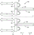
FIG. 1A is a cross-sectional view illustrating flow forces acting on an exemplary embodiment of a hydroelectric turbine according to the present disclosure;
FIG. 1B is a partial front view of a blade of the hydroelectric turbine of FIG. 1A;
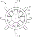
FIG. 2 is an elevation view of another exemplary embodiment of a hydroelectric turbine according to the present disclosure;
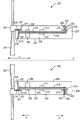
FIG. 3 illustrates a cross-sectional view of the hydroelectric turbine of FIG. 2 taken through line 3-3 showing the upper and lower halves of the cross-section;
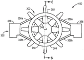
FIG. 4 is a front perspective view of an exemplary embodiment of a hydroelectric turbine system according to the present disclosure, the hydroelectric turbine system comprising a hydroelectric turbine, an anchoring system, and a bridge assembly;
FIG. 5 is a front elevational view of the hydroelectric turbine system of FIG. 4;
FIG. 6 illustrates a cross-sectional view of the hydroelectric turbine and bridge assembly of FIG. 4 taken along line 6-6, illustrating the upper and lower halves of the cross-section of the turbine;
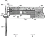
FIG. 7 is a partial detail view of the lower half of the cross-section of FIG. 6;
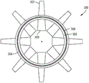
FIG. 8 is a rear cross-sectional view of an exemplary arrangement of stator segments on a bridge assembly according to the present disclosure;
FIG. 9 is an elevation view illustrating an exemplary embodiment of a rotor supported on a stator and bridge assembly with mounts for blades according to the present disclosure;
FIG. 10 is a partial detail view of a lower half of a cross-sectional view of another exemplary embodiment of a hydroelectric turbine according to the present disclosure; and
FIG. 11 is a partial detail view of a lower half of a cross-sectional view of yet another exemplary embodiment of a hydroelectric turbine according to the present disclosure.
Detailed Description
According to one or more exemplary embodiments of the present disclosure, energy in a fluid flow may be directly converted into electrical energy using magnets embedded in a rotor, wherein the rotor includes an inner rim and at least one blade of a hydrofoil type. The rotor may be supported for rotation about an outer surface of a stator, which may have a core embedded with windings. The fluid flow acts on the at least one blade to rotate the rotor, which in turn moves the rotor magnets past the stator windings to generate electrical energy in the core. Additional sets of magnets may be embedded in the rotor and stator housing to suspend and separate these components during rotation of the rotor, and also to prevent the rotor from being forced axially by the fluid flow out of alignment (e.g., upstream and/or downstream) with the stator or being pushed out of the stator housing.
As will be understood by those skilled in the art, the terms "upstream" and "downstream" may each refer to a direction relative to the current fluid flow, or relative to the direction of water flow in a body of water. Thus, for simplicity of explanation, as shown in fig. 1A, 3, 6 and 7, "upstream" for unidirectional flow (e.g., for river applications) may refer to a direction U opposite the fluid flow, e.g., in a direction from the rear to the front of the turbine in the axial direction of the turbine (indicated by Y in some of the figures). And, the term "downstream" may refer to a direction D along the fluid flow, which is, for example, a direction from the rear to the front of the turbine in the axial direction of the turbine. However, those skilled in the art will appreciate that there is no true "upstream" and "downstream" for bi-directional flow (e.g., for tidal applications with ebb and flow). Furthermore, while the overall movement of the fluid flow at any given time is generally in a single direction, the fluid flow through a hydroelectric turbine may also have some components of different directions.
As will be explained further below, the configuration of a hydroelectric turbine with the rotor disposed outside of the stator may provide a robust configuration of the turbine that potentially improves stability and strength, and reduces the amount of material used to construct the turbine structure.
In various further embodiments of the present disclosure, the rotor may be assembled on and supported by a bridge assembly that couples the hydroelectric turbine to an anchoring system configured to anchor the turbine in a fixed position within a fluid. The bridge assembly may be configured to maintain the turbine in a fluid flow and to support the turbine against axial and radial forces.
In various exemplary embodiments, the bridge assembly may be formed as a unitary component, e.g., from a continuous casting of the composite material. The bridging assembly may be removably attached to the vertical members of the anchoring system. For example, the anchoring system may be a triangular frame member arranged in a substantially horizontal plane, with the vertical member being arranged at or near the maximum width of the triangular frame member, such that the flow energy driven hydroelectric turbine is not unduly blocked. The bridging assembly and/or anchoring system may be designed to be manufactured on site, thereby saving or at least reducing the expense of transporting the assembly from the manufacturing facility to the installation site.
In various exemplary embodiments, the rotor may be configured as separate parts assembled on a portion of the bridge assembly, for example, an axially extending tongue of a central support cylinder. Each rotor portion may be an arcuate segment of a closed-loop (e.g., annular) rotor and configured to fit together around the outer circumference of a stator attached to a tongue of a bridge assembly such that there is no or very little space between circumferentially adjacent portions. For example, the rotor may be configured as a flexible band arranged radially outside the tongue of the stator and bridging assembly. For example, the stator and rotor may be transported from a manufacturing facility to an installation site for assembly to the anchoring system.
As described herein, the term "flexible" generally refers to the ability of the rotor band to bend without breaking. Thus, according to various exemplary embodiments of the present disclosure, the rotor may be considered to have a certain flexibility such that the rotor may have the form of a cylindrical band structure without being damaged.
Construction of hydroelectric turbines
Referring now to fig. 1A and 1B, an exemplary embodiment of a hydroelectric turbine 100 according to the present disclosure is illustrated. The hydroelectric turbine 100 includes a rotor 104 disposed radially outward of a stator 106. In this arrangement, one or more blades (of the hydrofoil type) 101 may extend radially inward and/or radially outward. For example, referring to the exemplary embodiment of fig. 1A, radially inwardly extending blade portions 103 and radially outwardly extending blade portions 102 may be provided. Both blade portions 102, 103 are arranged in the fluid flow (indicated by the arrows in fig. 1A), thereby rotating the rotor 104 relative to the stator 106 about the central axis Y. In various exemplary embodiments (see, e.g., FIG. 2), a plurality of blades may be mounted around the circumference of the rotor 104.
Mounting the rotor 104 outside of the stator 106 may, for example, allow the rotor 104, or at least the portion of the rotor 104 between the areas for mounting the blade portions 102, 103, to be constructed as a semi-rigid band that provides some flexibility over a large diameter (e.g., up to about 30 feet). In various exemplary embodiments, the rotor may be made of Kevlar (Kevlar) or carbon fiber material. For example, the rotor 104 shown in the embodiment of FIG. 1A may support (e.g., resist the effects of gravity) the rotor 104 in a substantially closed-loop configuration with the stator 106 disposed on the inside. Conversely, in configurations where the rotor is disposed inside the stator, the rotor may require more rigidity to maintain the outer surface of the rotor adjacent the inner surface of the stator. The rotor 104 in the configuration shown in fig. 1A may benefit from reduced weight, less material, and/or the use of less expensive materials due to the reduced support requirements of the rotor. Further, the rotor 104 may be relatively thin in the radial direction to minimize unproductive drag in the fluid flow.
The rotor 104 may be sleeved over the outer surface of the stator 106, as with a belt or rope on a wheel (except that the rotor is spaced a small distance from the stator when rotating because of the presence of the bearing system, as explained below), thereby allowing the rotor 104 to bend/flex slightly when rotating. Because the amount of material required to manufacture the rotor 104 is reduced, the rotor 104 may be more adaptable and less expensive to manufacture and transport. Further, when the rotor is disposed around the stator 106, the rotor 104 may be in tension rather than compression, while the stator 106 is in compression. This may allow the rotor 104 to have increased strength while using less material.
In one or more exemplary embodiments of the disclosed subject matter, blades of the turbine may be attached toward a leading edge of the rotor, and the blade portions may extend in generally opposite directions (e.g., radially away from a center of the rotor (radially outward) and radially toward the center of the rotor (radially inward)). As shown in fig. 1A and 1B, for example, the rotor 104 may have a blade 101 with a radially inwardly extending blade portion 103 and a radially outwardly extending blade portion 104 attached to the rotor. Arranging the rotor 104 outside of the stator 106 may facilitate the arrangement of the radially inwardly and radially outwardly extending blade portions 102, 103. Thus, the blade portions 102, 103 may collect energy from the flow of the fluid flow F away from the central axis of rotation Y and towards the central axis of rotation Y, respectively. This may help balance the forces acting on the rotor, thereby reducing the stress on the rotor 104 and allowing less material to be used in both the rotor 104 and the blades 101.
In various exemplary embodiments, each blade portion 102 may be an integral part of the respective blade portion 103 to form a single blade (of the hydrofoil type) 101. Alternatively, in various further embodiments, each blade portion 102 may be formed as a separate part from the respective blade portion 103 and subsequently attached thereto to form a single blade 101. In yet different further embodiments, the blade portions 102, 103 may be formed as separate parts from each other and attached to the rotor 104 separately.
According to various exemplary embodiments of the present disclosure, the location where each blade 101 (or an already coupled blade portion) is attached to the rotor 104 may serve as a fulcrum for that blade. Thus, as shown in fig. 1A and 1B, as the blade 101 sweeps the fluid flow, the flow energy over the radially inwardly extending (e.g., within the circumference of the rotor) blade portion 103 of the blade 101 and the flow energy over the radially outwardly extending (e.g., outside of the circumference of the rotor) blade portion 102 of the blade 101 may act to balance the moments. This balancing of flow energy on the rim of the rotor may allow for the use of less structural material in manufacturing both the blades and the rotor.
As shown in FIGS. 1A and 1B, because the stator 106 supports the rotor 104 and the blades 101 on the rotor 104 are configured in a balanced arrangement (e.g., radially inward and radially outward), the amount of material (e.g., expensive composite material) required to construct the rotor 104 may be reduced, which may also reduce the cost of manufacturing and assembly, as well as facilitate installation of the turbine 100.
Referring now to FIGS. 2 and 3, another exemplary embodiment of a hydroelectric turbine 200 according to the present disclosure is illustrated. Similar to the embodiment of FIGS. 1A and 1B, the hydroelectric turbine 200 includes a rotor 204 disposed radially outward of a stator 206. The turbine 200 may be positioned in a body of water (e.g., a river or ocean) or in the path of a fluid flow and remain stationary within the moving stream or, alternatively, be dragged within the fluid to create a flow effect. One or more blades 201 may be attached to the rotor 204, for example, at a leading edge (e.g., upstream end) of the rotor. Each blade 201 may have a radially inwardly extending blade portion 202 and a radially outwardly extending blade portion 203, which may be formed separately or as an integral part, as described above. As shown in fig. 3, in various exemplary embodiments, the stator 206 may have a generally L-shaped cross-section with a short leg 205 of the L extending radially outward to align with the rotor 204 and a long leg 207 of the L extending axially along the inner circumferential surface of the rotor 204.
In various embodiments, the rotor 204 may include one or more power generating magnets that are arranged relative to one or more corresponding power generating elements of the stator 206 when installed in the turbine 200. In various further embodiments, the stator 206 may include one or more power generating magnets arranged relative to one or more corresponding power generating elements of the rotor 204. The power generating element may, for example, include at least one coil 208 having windings configured to generate electrical energy in response to rotational movement of a power generating magnet 209 on the rotor 204.
For example, the rotor 204 may include one or more magnets 209 for generating electricity that are arranged radially adjacent to, but spaced from, at least one coil 208 of the stator 206. The magnets 209 may be mechanically attached to the inner edge 210 of the rotor 204 or may be disposed within the interior of the rotor 204 proximate the inner edge 210. Thus, the fluid flow interacting with the blades 201 causes the rotor 204 to rotate on the outer side surface of the stator 206. And, rotation of the magnets 209 in the rotor 204 induces a voltage in the coils 208 disposed in the stator 206 (e.g., disposed in the stator housing). The coils 208 may be connected together in a manner to generate electrical energy at a desired voltage and/or current. The generated electricity may then be transported over electrical wires (not shown) for subsequent use or storage, for example, over one or more transmission lines or conductors connected to a land-based power grid.
In various exemplary embodiments, adjacent blades 201, whether they extend radially inward and/or radially outward, may be spaced at an angle around the circumference of rotor 204, the angle between adjacent blades 201 ranging from about 20 degrees to about 60 degrees.
In various exemplary embodiments, one or more sets of levitation magnets 211, 212 may be arranged to radially align and levitate rotor 204 relative to stator 206. In an exemplary embodiment, the magnet 212 may be mechanically attached to the inner edge 210 of the rotor 204 or disposed within the body of the rotor 204 near or at the inner edge 210, and the magnet 211 may be mechanically attached to the radially outer surface of the stator 206 or disposed within the body of the rotor 206 near or at the radially outer surface. The sets of magnets 211, 212 may be arranged radially adjacent to each other (but spaced apart) with like poles facing each other to generate a repelling force in a substantially radial direction. The repulsive force between the one or more sets of magnets 211, 212 may assist in maintaining the alignment of the rotor 204, and thus the rotor, relative to the stator 206, relative to its rotational axis Y.
In various additional exemplary embodiments, one or more sets of levitation magnets 213, 214 may be arranged to help maintain the relative axial positioning of rotor 204 with respect to stator 206. Magnets 213 may be mechanically attached near or at the end of inner rim 210 of rotor 204 adjacent to short leg 205 of stator 206 (e.g., at the downstream end of inner rim 210), or disposed within the body of rotor 204 near or at the end of rotor 204 adjacent to short leg 205 of stator 206. And, the magnet 214 may be mechanically attached to the radially extending surface 223 of the short leg 205 of the stator 206, or disposed within the body of the short leg 205 of the stator 206 proximate to the radially extending surface 223 of the short leg 205 of the stator 206. One or more sets of magnets 213, 214 may be disposed axially adjacent (but spaced apart) from each other with like poles facing each other to generate a repelling force in a substantially axial direction (e.g., parallel to the axis of rotation Y). The repulsive force between the one or more sets of magnets 213, 214 may thus assist in maintaining alignment of the rotor 204 relative to the stator 206 and prevent the rotor 204 from moving axially relative to the stator 206 (e.g., the rotor is pushed downstream) due to the flow of fluid or other forces.
In various further embodiments, the short leg 205 of the stator 206 may serve as a parking support to aid one or more sets of magnets 213, 214 and prevent the rotor 204 from potentially moving in a direction toward the short leg 205 and out of axial alignment with the stator 206. The short leg 205 of the stator 206 may also help prevent the rotor 204 from moving axially relative to and out of alignment with the stator 206 during shutdown or maintenance of the turbine 200. Alternatively, a separate shutdown support may be provided, wherein the magnet 214 may be disposed within a separate stop. The separate shutdown support may then be attached to the short leg 205 of the stator 206 such that the magnet 214 repels the magnet 213 of the rotor 204.
In various additional exemplary embodiments, rotor 206 may further include one or more sets of magnets 216, 217, which, like magnets 213, 214, may be configured to help maintain axial alignment of rotor 204 with respect to stator 206. In an exemplary embodiment, as shown in fig. 3, for example, a backstop 218 (or cap) may be provided at the opposite end of the stator 206 to prevent the rotor 204 from slipping off the front end of the stator 206 (opposite end of the short leg 205 of the L-shape), and may further include one or more magnets 216. The magnet 217 may be mechanically attached to the inner edge 210 of the rotor 204 or disposed within the body of the rotor 204 proximate the inner edge 210. The magnet 216 may be mechanically attached to the radially extending surface 215 of the backstop 218 or disposed within the body of the backstop 218 proximate the radially extending surface 215 of the backstop 218. One or more sets of magnets 216, 217 may be disposed adjacent to each other (but axially spaced) with like poles facing each other to generate a repelling force in a substantially axial direction. The repulsive forces between the one or more sets of magnets 216, 217 may assist in maintaining the axial alignment of the rotor 204 relative to the stator 206 and prevent the rotor 204 from moving axially relative to the stator 206 and out of alignment with the stator due to flow or other forces.
The backstop 218 (or cap) may act as a stop to assist one or more sets of magnets 216, 217 and prevent the rotor 204 from potentially moving axially in a direction away from the short leg 205 of the stator 206 (e.g., upstream) and out of axial alignment with the stator 206. As above, the forward stop 218 may also help prevent the rotor 204 from moving axially relative to the stator 206 and from coming out of alignment with the stator during, for example, shutdown or maintenance of the turbine 200. Alternatively, the stator 206 may be provided with a separate radial extension instead of the kick 218, in which case one or more magnets 216 may be provided within this separate radial extension of the stator 206 such that the one or more magnets 216 repel the magnets 217 of the rotor 204.
As described above, to maintain alignment of the rotor 204 with the stator 206 and to prevent the rotor 204 from being forced out of axial alignment with the stator 206 (e.g., pushed downstream or upstream by fluid flow), the repelling magnets 211, 212; 213. 214 and 216, 217 may be embedded in the outer periphery of the rotor and in the stator (e.g., in the stator housing), e.g., in the radial direction and parallel to the axis of rotation Y of the turbine 200. Due to the arrangement of the sets of magnets 211, 212; 213. 214, and 216, 217, the rotor 204 may be configured to float (levitate) freely relative to an outer circumferential surface of the stator 206 as the rotor 204 rotates around the stator 206. Thus, the rotor 204 may be held in place relative to the stator 206 without mechanically attaching the rotor 204 to the stator 206 or to a turbine housing (not shown). This may have the advantage of increasing turbine efficiency by reducing friction, among other advantages. Other configurations and arrangements of magnets to support the rotor relative to the stator may also be used, for example, as described in U.S. patent publication No.2012/0211990, which is incorporated by reference above.
As will be understood by those skilled in the art, the set of levitating magnets 211, 212 shown and described with respect to fig. 3; 213. 214, and 216, 217 are merely exemplary, may have different arrangements and configurations, and/or may be replaced by or used with any known support mechanism and/or system. Various embodiments of the present disclosure contemplate, for example, using a hydraulic Bearing (which includes, for example, a support system of a resilient polymer alloy, such as the Thordon COMPAC Bearing commercially available from Thordon Bearing inc. of burlington, ontari) as a radial Bearing instead of levitation magnets 211, 212, or as an axial Bearing instead of levitation magnets 213, 214 and 216, 217. Various additional embodiments of the present disclosure contemplate the use of water lubricated bearings made of wood or composite materials, such as wood composite materials commercially available from Lignum-Vitae North America of Virginia Politan, in place of the levitation magnets 211, 212 and/or in place of the levitation magnets 213, 214 and 216, 217.
As shown in fig. 10, this embodiment contemplates, for example, using strips of wood or wood composite material (e.g., Lignum-Vitae)228 disposed along an outer circumferential surface 229 of the stator 206 (e.g., 2x4 pieces of composite material 228 are pushed into slots 230 within the body of the stator 206) to serve as radial supports between the rotor 204 and the stator 206. As also shown in FIG. 10, this embodiment further contemplates the use of intermeshing teeth 231 and 233 to support axial forces of the turbine 200. A row of teeth 231 of wood or wood composite material (e.g., Lignum-Vitae) may, for example, be attached (e.g., by pegs 232) to an outer circumferential surface 229 of the stator 206 and extend into slots 234 (e.g., forming teeth 233) formed in an inner circumferential surface (e.g., inner rim 210) of the rotor 204. The groove 234 may be fitted with a bearing surface, such as a stainless steel ring (not shown), configured to slide on the sides of the teeth 231. In this manner, the fluid (e.g., seawater) within each slot 234 may provide a hydrodynamic bearing effect to withstand the axial loads of the turbine 200.
Nonetheless, as will be further understood by those skilled in the art, if other types of support systems are used, it may be desirable to align the surfaces of the rotor 204 and stator 206 with one another to prevent hydroelectric effects. Those skilled in the art will further appreciate that depending on the particular turbine application, different arrangements of levitation magnets and/or other support mechanisms may be used to provide the desired radial and/or axial alignment of the rotor relative to the stator. For example, in applications where the turbine is placed in a river and energy is collected from flow in only one direction, the axial support would only need to be placed at one end of the turbine.
In various additional embodiments of the present disclosure, for example, the turbine 200 may further include one or more support materials disposed between the stator 206 and the rotor 204. For example, the stator 206 may have a water lubricated (or other fluid lubricated) bearing material 219 attached to a radially outer surface of the stator opposite the inner edge 210 of the rotor 204. Alternatively, the support material 219 may be an integral part of the outer surface of the stator 206.
The support material 219 may assist the one or more sets of magnets 211, 212 in maintaining the center alignment of the rotor 204 with respect to the rotational axis Y of the turbine 200. Alternatively, the rotor 204 may have a friction-reducing smooth surface (e.g., a polished metal or ceramic type surface) at its inner edge 210 that will contact the bearing material 219, for example, when the magnets 211, 212 fail to maintain the center of the turbine 200 in alignment. Such surfaces may help reduce friction during periods of misalignment. Furthermore, the support material 219 may occupy a majority, or at least a substantial portion, of the radial area between the outer surface of the stator 206 (and the coils 208 of the stator 206) and the inner edge 210 of the rotor 204 (and the magnets 209 of the stator 204), thereby displacing some fluid (e.g., saline) that would otherwise be contained therebetween.
The bearing material 220 may also be disposed between the stator 206 and the rotor 204 at an end of the turbine 200 opposite the blades 201 (e.g., a downstream end of the turbine 200), for example, between a radially extending rim 225 of the rotor 204 and the short leg 205 of the L-shape of the stator 206 (i.e., the radially extending surface 223). Alternatively, the support material 220 may be attached to the short leg 205 of the stator 206 or formed as an integral part of the leg 205 of the stator 206. Support material 220 may assist magnets 213, 214 in maintaining axial alignment of rotor 204 relative to stator 206. Alternatively, the edge 225 of the rotor 204 extending radially therealong may have a friction-reducing smooth surface (e.g., a polished metal, ceramic, or composite surface) that will contact the bearing material 220 when the magnets 213, 214 fail to maintain axial alignment of the turbine 200. The support material 220 may also occupy a majority, or at least a substantial portion, of the axial area between the short leg 205 of the stator 206 (and the magnets 214 of the stator 206) and the radially extending rim 225 of the rotor 204 (and the magnets 213 of the rotor 204), thereby expelling some fluid (e.g., saline) that would otherwise be contained therebetween.
In a similar manner, the support material 221 may additionally be disposed between the forward dam 218 and the rotor 204 at an end of the turbine adjacent the blades 201 (e.g., an upstream end of the turbine 200), for example, between the radially extending edge 227 of the rotor 204 and the radially extending surface 215 of the forward dam 218. For example, the support material 221 may be attached to the backstop 218 or formed as an integral part of the backstop 218. The support material 221 may assist the magnets 216, 217 in maintaining axial alignment of the rotor 204 relative to the stator 206. Alternatively, the radially extending edge 227 of the rotor 204 may have a friction-reducing smooth surface (e.g., a polished metal, ceramic, or composite surface) that will contact the bearing material 221 when the magnets 216, 217 fail to maintain axial alignment of the turbine 200. The support material 221 may also occupy a majority, or at least a substantial portion, of the axial area between the surface of the forward dam 218 (and the magnets 216 of the forward dam 218) and the radially extending rim 227 of the rotor 204 (and the magnets 217 of the rotor 204), thereby expelling some fluid (e.g., saline) that may otherwise be contained therebetween.
According to various exemplary embodiments, the bearing material 219, 220, 221 may be a fluid-lubricated non-magnetic material. Such materials may include, but are not limited to, ceramic or diamond support materials, composite materials, or thermoplastics or other polymers. Those skilled in the art will appreciate that the illustrated support materials 219, 220, 221 are merely exemplary, may have different configurations, sizes, and/or arrangements between the rotor 204 and the stator 206, and may be formed of different materials without departing from the scope of the present disclosure and claims.
In an alternative to the above-described embodiments, for example, one or more support materials 219, 220, 221 may be attached to or formed as part of the rotor 204, and the respective opposing surfaces of the stator 206 or the forward stop 218 are polished metal, ceramic, or composite surfaces. In yet another alternative embodiment, one or more support materials 219, 220, 221 may be attached to or formed as part of the rotor 204 while other support materials are attached to or formed as part of the stator 206. In yet another alternative embodiment, the one or more support materials 219, 220, 221 may be formed as a unitary component and disposed between the rotor 204 and the stator 206.
Those skilled in the art will also appreciate that the turbines 100, 200 illustrated in fig. 1-3 and described above are merely exemplary, and that the blades 101, 201, rotors 104, 204, and stators 106, 206 may have different configurations, sizes, shapes, and/or arrangements without departing from the scope of the present disclosure and claims. Further, those skilled in the art will appreciate that the turbines of the present disclosure may be configured to operate in fluid flows of different and varying directions (as indicated by the multi-directional arrows showing fluid flow F in the figures), and to operate in ebb and flow, such as tidal flows, and in flow from only one direction, such as a river. For example, for turbines used in different environments (e.g., ocean and river), the shape of the blades 101, 201 may be different to optimize the potential energy collection from the two-way flow stream and the one-way flow stream. In various embodiments, for example, blades swept back in both the tangential and axial directions may be used in applications such as rivers (i.e., for unidirectional flow), as described in international patent application PCT/US2015/30373 entitled "component for hydroelectric turbine," filed 5, 12/2015, which is incorporated herein by reference in its entirety.
Turbine support structure and system including the same
Referring now to FIGS. 4-7, an exemplary embodiment of a hydroelectric turbine system 400 is shown that includes a hydroelectric turbine 300 and a bridge assembly 350, and has an anchoring system 370. Similar to the hydroelectric turbines 100, 200 described above, the hydroelectric turbine 300 includes a rotor 304 disposed radially outward of a stator 306 (see FIGS. 6 and 7) that remains stationary relative to the rotor 304. The turbine 300 further includes blades 301 attached to and extending radially inward and/or radially outward from the rotor 304 (both directions are depicted in the exemplary embodiment of FIGS. 4-7). As shown in fig. 6 and 7 and described further below, the rotor 304 is radially spaced from and substantially centered about the stator 306, which may be supported on axially extending tongues 352 of a central support ring 354 of the bridge assembly 350. The bridge assembly 350 may be coupled to an anchoring system 370 that maintains the turbine 300 in a fixed position within a fluid stream (e.g., a river, ocean, or other moving fluid).
As shown in fig. 4 and 5, in various exemplary embodiments, the bridge assembly 350 includes an attachment block 356, one or more laterally extending support arms 358, and a central support ring 354. The attachment blocks 356 may be disposed at opposite horizontal ends (in the orientation of fig. 4 and 5) of the bridge assembly 350. One or more support arms 358 may extend laterally inward from the attachment blocks 356 and support the central support ring 352 centered between the attachment blocks 356. For example, the support arms 358 may extend in a plane substantially perpendicular to the axis of rotation Y of the turbine 300. Alternatively or additionally, the support arms 358 (and/or the vertically extending columns 374 of the anchoring system 370) may be inclined forward or rearward, e.g., at an angle upstream or downstream relative to a plane perpendicular to the axis of rotation Y of the turbine 300.
As shown in fig. 4 and 5, the support arms 358 may also extend upward or downward from the attachment block 356 at an angle relative to horizontal such that the support arms 358 are not aligned with the length of the blade 301 as the blade 301 rotates past the support arms 358. This configuration may avoid or at least reduce the blockage of flow energy interacting with the blades 301 by the support arms 358. In various embodiments, for example, a support arm 358 arranged to support a top portion (i.e., upper arm 358a) of the turbine 300 and a bottom portion (i.e., lower arm 358b) of the turbine 300 may extend from the attachment block 356 in a direction having a horizontal component and a vertical component, which in the orientation of FIG. 4 is at an angle relative to the horizontal. For example, the end of the upper arm 358a proximate the attachment block 356 may extend upwardly from a vertical height just above the center of the center support ring 354 to a vertical height coincident with or just below the top portion of the center support ring 354. And, the end of the lower arm 358b proximate the attachment block 356 may extend from a vertical height just above the center of the center support ring 354 to a vertical height coincident with or just above the bottom portion of the center support ring 354.
According to various exemplary embodiments, the central support ring 354 may be a generally tubular segment, or a cylinder having an open or hollow center (e.g., the central support ring 354 forms a hollow cylinder or has an open-center configuration and is not itself hollow) and having a generally annular cross-section. Applications of this hollow cylindrical structure may have a higher specific strength per unit weight than a solid member, and may require less material. As shown in fig. 6, the center support ring 354 includes a tongue 352 that projects toward the vanes 301 (e.g., upstream) and is configured to support the stator 306 on a radially outer circumferential surface of the tongue 352.
As will be explained in more detail below, the bridge assembly 350 may be formed separately from and coupled to the anchoring system 370. According to various exemplary embodiments, for example, the anchoring system 370 may include a triangular frame base 372 having one or more vertically extending support posts 374. As shown in fig. 4, the attachment blocks 356 of the bridge assembly 350 may then be coupled to the vertical support posts 374 of the anchoring system 370. In various embodiments, for example, each attachment block 356 may have a protrusion at its bottom end that slides into a corresponding recess at the top portion of one of the vertical support posts 374. Optionally, in various further embodiments, each attachment block 356 may have an opening (e.g., a recess) at its bottom end that receives a corresponding protrusion at a top portion of one of the vertical support posts 374. In yet another alternative embodiment, each attachment block 356 may have a recess at its bottom end, and each vertical support column 374 may have a recess at its top end, each recess configured to receive an end of a pin. As will be appreciated by those skilled in the art, various other attachment structures and methods may be used to removably and securely couple the bridge assembly 350 to the anchoring system 370, in accordance with one or more contemplated embodiments.
As shown in fig. 4, the anchoring system 370 includes a base having feet configured to be disposed on a substrate surface, such as a riverbed or a seabed. In various embodiments, for example, the anchoring system 370 may include a triangular frame-like base 372 having a forward leg portion 376 disposed upstream and horizontally centered with respect to the axis of rotation Y of the turbine 300 and two aft leg portions 378 horizontally spaced from the axis of rotation Y. One or more support members 380 may extend generally horizontally in the upstream direction to connect each rear foot portion 378 to the front foot portion 376. Optionally, one or more rear support members 382 may also extend generally horizontally in a direction transverse to the flow to interconnect the rear feet 382.
As above, the anchoring system 370 may also include one or more substantially vertically extending posts 374 configured to couple to the attachment blocks 356 of the bridge assembly 350. In various embodiments, for example, each vertical post 374 may be attached to or extend from a portion of support member 380 between forefoot portion 376 and corresponding rearfoot portion 378. As will be appreciated by those skilled in the art, additional structure may also be coupled to each vertical column 374 and each respective support member 380 to reinforce the vertical columns 374. For example, in various exemplary embodiments, one or more cross brace arms 384 may be disposed between vertical column 374 and support member 380.
According to various exemplary embodiments of the present disclosure, the bridge assembly 350 and/or the anchoring system 370 may be formed of concrete and may be manufactured at a facility near the installation site. This allows relatively heavy and large-scale portions of the turbine system to be made locally at the installation site as needed, thereby reducing transportation and manufacturing costs. Conversely, as described in more detail below, the rotor 304 and stator 306 components may be manufactured remotely as needed and packaged into blocks for cost-effective transportation to and assembly at an installation site.
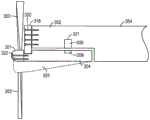
For example, the entire bridge assembly 350 may be cast as a single, integral, unitary piece (e.g., by continuous casting of material without interruption) with its four structural arms 358, attachment blocks 356, and support ring 354 at its center. In various exemplary embodiments, for example, the entire bridge assembly 350 may be cast by continuous casting of concrete (e.g., the bridge assembly is formed of a composite material such as concrete with rebar). In this way, the tongue 352 may be attached to the support ring 354 (e.g., by continuous casting of concrete extending all the way into the tongue 352), and the annular tongue 352 is designed to structurally reinforce the rotor 304 and its blades 301 as the blades rotate. As shown in fig. 11, in this embodiment, the L-shaped stator 306 (i.e., having the short arm 305 and the long arm 307) may be eliminated and the stator coil 308 may be embedded in the slot 321 formed in the tongue 352.
Alternatively, the bridge assembly 350 may be constructed from separate, independent sections that are cast on or near the installation site. For example, the attachment blocks 356, the arms 358, and/or the support ring 354 may be separately cast and then coupled to other components of the bridge assembly 350. In this embodiment, the tongue 352 may be mechanically attached to the support ring 354.
Additionally or alternatively, the anchoring system 370 may also be cast as a single, integral, unitary piece (e.g., by continuous, uninterrupted casting of material). Such fabrication may facilitate optimization or at least improved strength with a minimal amount of material used. Similar to the bridge assembly 350, the anchoring system 370 may be formed, for example, from a composite material such as concrete with steel reinforcement.
Referring now to the partial (lower half) view of the detail of FIG. 7, as mentioned above, the hydroelectric turbine 300 includes a rotor 304 disposed radially outward of a stator 306. Similar to the embodiment of fig. 1-3, the stator 306 may have a generally L-shaped configuration in cross-section with a long leg 307 of the L-shaped configuration extending axially along the inner circumference of the rotor 304 and a short leg 305 of the L-shaped configuration extending radially outward to align with the rotor 304. The rotor 304 may include one or more power-generating elements that are arranged relative to and configured to work with one or a pair of corresponding power-generating elements of the stator 306 when installed in the turbine 300. In various exemplary embodiments, for example, as described above, the rotor 304 may include one or more magnets 309 disposed radially adjacent (but spaced apart from) coils 308 on the stator 306. The magnet 309 may be mechanically attached to or embedded in the inner circumferential surface of the rotor 304, or disposed inside the rotor 304 near the inner circumferential surface. Thus, as described above, the flow energy may cause the rotor 304 to rotate around the outer circumferential surface of the stator 306 through the interaction of the fluid flow with the vanes 301. The rotation of the magnets 309 in the rotor 304 induces a voltage in the coils 308 of the stator 306. The plurality of coils 308 may be connected together in a manner to generate electrical energy at a desired voltage and/or current, and the generated electricity may then be transported for subsequent use or storage, for example, by one or more transmission lines or conductors (not shown) connected to a land-based power grid.
In various exemplary embodiments, magnets 309 and coils 308 are each covered in marine epoxy to permanently secure them in place and seal them from the fluid (e.g., seawater).
Although not shown in fig. 7, as shown with reference to fig. 3 and described above, in addition to the power generating magnets 309, one or more sets of levitation magnets may be disposed and arranged relative to the rotor and stator to provide magnetic levitation and alignment of the rotor relative to the stator in the radial direction (see magnets 211, 212 of fig. 3) and/or the axial direction (see magnets 213, 214 and 216, 217 of fig. 3) as the rotor rotates around the stator.
Also similar to the embodiment of FIGS. 1-3, the turbine 300 may have a forward stop 318 disposed at an upstream end of the turbine. As described above, the forward stop 318 may prevent the rotor 304 from moving axially (e.g., upstream) relative to the stator 306 during rotation of the turbine 300 and/or prevent the rotor 304 from moving axially out of alignment with (e.g., away from) the stator 306 during, for example, shutdown or maintenance. Alternatively, the stator 306 may be provided with a separate radial extension at the upstream end in place of the forward dam 318, in which case a aft dam (not shown) may be provided at the downstream end of the stator 306 instead of or in addition to a flange (e.g., the short leg of a stator having an L-shaped configuration as described above with reference to fig. 3).
As also above, in various exemplary embodiments, the turbine 300 may include support material disposed at various locations between the stator 306 and the rotor 304. In various embodiments, for example, the stator 306 may have a water lubricated (or other fluid lubricated) bearing material 319 attached to a radially outer surface of the stator opposite the inner circumferential surface of the rotor 304. Alternatively, the support material 319 may be an integral part of the outer surface of the stator 306. As noted above, the present disclosure further contemplates various other variations and configurations of the support material 319.
Those skilled in the art will appreciate that the hydroelectric turbine system 400 comprising the hydroelectric turbine 300, the bridge assembly 350, and the anchoring system 370 described above and illustrated in fig. 4-7 is merely exemplary, and that the arrangement, positioning, and number of the structural components of the turbine system may be varied without departing from the scope of the present disclosure and claims.
Method of assembling and manufacturing water power transmission and system
As described above, the bridge assembly 350 and/or the anchoring system 370 may be designed to be manufactured on-site, thereby saving or at least reducing the expense of transporting the assembly from the manufacturing facility to the installation site. And, the stator 306 and rotor 304 may be manufactured at a factory and transported from the manufacturing factory to an installation site for assembly onto the anchoring system 370.
In various embodiments, for example, the rotor 304 may be formed from multiple segments that are assembled together in the field. Referring to fig. 8, for example, the rotor 304 may be formed from a plurality of arc segments 310. Each arcuate segment 310 may be substantially identical to each other, but one or more segments 310 may include wires or cables 312 (from the stator 306) for transporting electricity generated by the stator 306 to, for example, a land-based power grid for subsequent use or storage.
As shown in FIG. 8, each segment 310 may be a composite arc segment, and all of its required elements (e.g., power generation elements, suspension elements, and/or support elements) are installed at the manufacturing site and transported to the installation site of the turbine 300 in a compact form. Electrical connections may be provided at circumferentially adjacent edges of the individual segments 310 to electrically couple the segments together. The circumferentially adjacent edges may also be configured to mechanically couple the segments 310 together, for example, by corresponding flanges such as shown at region 314 in fig. 8. The present disclosure further contemplates other configurations of the ends of each segment 310 such as, but not limited to, a dovetail, termination, miter, or any other type of interface configuration known to those skilled in the art. The electrical connection and/or mechanical coupling between adjacent segments 310 may further be achieved by, for example, epoxy, soldering, welding, or any other connection technique.
In various embodiments, each rotor section 310 may have an arcuate profile when viewed from the front of the turbine 300 as shown in FIG. 8, and may have a generally rectangular cross-sectional profile when viewed from the side of the turbine 300 as shown in FIG. 7. As further shown in FIG. 7, the stator 306 may have an L-shaped cross-sectional profile when viewed from the side of the turbine 300. In the embodiment of FIG. 7, for example, the stator 306 may be attached to the support ring 354 at the long leg 307 of the L-shaped configuration or at a flange formed by the short leg 305 of the L-shaped configuration. For example, bolts, screws, rivets, nails, or any other attachment mechanism may be used to attach the stator to the surface of the support ring 354. Alternatively or additionally, the stator 306 may be attached to the support ring 354 by applying an adhesive material (such as glue, epoxy, or cement) between corresponding surfaces of the stator 306 and the support ring 354. In various further embodiments, as shown in FIG. 7, the forward stop 318 may also be configured to attach to the support ring 354, such as by bolts 320 at the forward face of the tongue 352, to retain the rotor 304 and stator 306 to the support ring 354.
As also shown in FIG. 7, the blades 301 may be attached to the rotor 304, e.g., at an upstream end of the rotor. In various embodiments, the blade 301 may be attached to the rotor by bolts 322, but screws, rivets, nails, or any other attachment mechanism may be used to attach the blade 301 to the rotor 304. In this way, the blade 301 is easily accessed and removed from the rotor 304 for replacement (e.g., in the event of damage to the blade 301), or for changing/replacing the blade 301 to a different size or configuration of the blade 301 to accommodate, for example, different flow strengths. For example, the flow of river water is often variable and can vary dramatically over the course of a year, with strong and higher velocities during spring overflows and weak and lower velocities during the end of the summer months or dry seasons. Accordingly, it is desirable to vary the size of the blades 301 of the turbine 300 based on the flow conditions of the river or other body of water in which the turbine 300 is deployed. For example, larger vanes 301 having a larger surface area may be used in low flow conditions than vanes 301 used in high or normal flow conditions.
In various further embodiments, as shown in phantom in fig. 11, one or more blades 301 may include an outer extension 325 that at least partially surrounds an outer surface of rotor 304. In this embodiment, the blade may be attached to the front of the rotor 304 by bolts 322 and to the outer surface of the rotor 304 by bolts (not shown), thereby allowing the blade 301 to more fully transfer forces into the rotor 304.
As described above, the blade 301 may include a radially inwardly extending blade portion 303 and a radially outwardly extending blade portion 302, which may be formed as a unitary piece for attachment to the rotor 304. As shown in fig. 9, in various exemplary embodiments, the blades 301 may be regularly arranged around the circumference of the rotor 304 at angular intervals ranging from about 20 degrees to about 60 degrees, i.e., the angular intervals of adjacent blades range from about 20 degrees to about 60 degrees.
The arrangement of the blades 301 such that the blade portions 303, 302 extend inwardly and outwardly relative to the rotor 304 may, for example, help to balance forces acting on the rotor 304. For example, the bending moment created by the forces acting on the blade 302 may be balanced by the bending moment created by the forces acting on the blade 303. Furthermore, because the rotor 304 is disposed radially outward of the stator 306, the stator 306 and the tongue 352 of the support ring 354 underlying the stator 306 may support the rotor 304 in a radial direction. Thus, the rotor 304 may be made thinner and more flexible than required for turbine configurations that use cantilevered blades extending radially inward from the rotor disposed inside the stator.
In this way, the rotor 304 may have a substantially uniform, relatively thin radial thickness along its circumference, thereby having a flexible band-like structure that allows the rotor 304 to wrap around the outer surface of the stator 306, similar to a band or rope on a wheel, but with opposing surfaces spaced from one another as explained above. This arrangement may allow the rotor 304 to bend/flex slightly as it rotates. Because the amount of material required to manufacture the rotor 304 is reduced, the rotor 304 may be more adaptable and less expensive to manufacture and transport. Furthermore, because the rotor 304 may be disposed over the stator 306 in tension (rather than compression), the rotor 304 may also have increased strength.
Furthermore, the radially symmetric arrangement of the blades 301 with respect to the rotor may result in a greater sweep in the fluid. Such a configuration may, for example, have the added advantage of lower drag (which is non-productive) than a turbine having only radially inwardly extending blades. Thus, for the same amount of drag, more electrical energy can be generated with the system of the present disclosure, or conversely, with less drag, a smaller turbine can generate the same electrical energy, thereby requiring a smaller anchoring system.
As above, according to various embodiments, a method for manufacturing and installing a hydroelectric turbine system (which is, for example, the turbine system 400) may include casting the integrated anchoring system 370 and the integrated bridge assembly 350 at a location proximate to an installation site of the turbine system 400. The method may further include manufacturing the rotor section 310, stator 306, and/or blade 301 at a location remote from the installation site, and packaging the unassembled rotor 304, stator 306, and/or blade 301 for transport to the installation site. Thus, the manufacture of the bridge assembly 350 (e.g., with the tongue 352 extending below the stator housing (not shown)) and the anchoring system 370 may be performed very close to the installation site, while the rotor 304, stator 306, and blades 301 are manufactured elsewhere and transported for assembly at the installation (i.e., deployment) site. In other words, the bridge assembly 350 and the anchor assembly 370 may be manufactured at different locations than the rotor 304, stator 306, and blade 301.
As above, the integrated anchor assembly 370 may include a substantially horizontal triangular frame-like base 372 having one or more support members 380. The anchoring system 370 may also include a pair of posts 374, each of which extends in a substantially vertical direction (although it may be angled upstream or downstream) from one of the support members 380. The integrated anchor assembly 370 may be installed at an installation site, for example, by contacting the feet 376, 378 of the assembly to a base surface (e.g., river or sea bed) at the bottom of a body of moving water. In various embodiments, the feet 376, 378 may include features designed to grip the surface of a substrate to prevent the turbine system 400 from being moved by a moving body of water. For example, the feet 376, 378 may include cleats. Alternatively, the feet 376, 378 may be coupled to a structure that is pre-inserted into the base surface (which is, for example, a tower in the base surface).
The unitary bridge assembly 350 may be manufactured to include one or more attachment blocks 356, a plurality of support arms 358, and a central support ring 354 coupled to the ends of the support arms 358. The integral bridge assembly 350 may be installed at the installation site by coupling the attachment blocks 356 to respective ends of the vertical posts 374 of the anchoring system 370. According to various exemplary embodiments, the anchoring system 370 may be installed at the installation site in the moving body of water, after which the bridge assembly 350 is lowered onto the vertical columns 374 in the moving body of water. In an alternative embodiment, the anchoring system 370 and the bridge assembly 350 may be coupled together before they are installed in the body of moving water.
The method may further include assembling a plurality of pre-manufactured rotor segments 310 (i.e., at the manufacturing facility) on the support tongues 352 of the central support ring 354 of the bridge assembly 350 (via the long legs 307 of the stator 306). For example, as described above and shown in fig. 8, the rotor segments 310 are substantially arc-shaped segments that fit together on the outer peripheral surface of the long leg 307 of the stator 306 (which is coupled to the support tongue 352) to form the rotor 304 of the turbine 300. The rotor 304 may, for example, be made of a composite material that encapsulates power generation components, and electrical cables may be connected to the stator 306 to transport the generated electricity from the turbine system 400 for use or storage. In various embodiments, for example, segment 310 (or a composite arc segment) may be manufactured with a pre-formed groove for the axial support system (e.g., magnets 213 and 217). The groove can be precisely positioned for insertion of a pre-manufactured groove Blocks of formula (lb), each block containing magnets of the correct polarity and given orientation. Once inserted into the slot, eachThe block of formula (la) may, for example, then be bathed with marine epoxy to permanently fix the block in place and seal it from fluids (e.g., seawater).
For example, as described above, the rotor 304 may have a flexible band-like structure that is radially spaced from the outer circumferential surface of the stator 306 and centered relative to the central support ring 354 and/or the stator 306. The forward stop 318 may then be installed to hold the rotor 304 in place relative to the stator 306. As described above, the forward stop 318 may be attached to the stator 306 or to the support tongue 352 of the bridge assembly 350.
As described above, according to various embodiments, the rotor 304 may be configured as a series of arcuate segments 310, for example, each segment extending at an angle (which may range from about 20 degrees to about 60 degrees). The segment 310 may be cast to provide a connection point for subsequent attachment of the blade 301. To manufacture the rotor 304 (e.g., rotor band), in various exemplary embodiments, the segments 310 may be mechanically fastened (temporarily) around the outside of a suitably shaped and sized mandrel. Strips of carbon fibre impregnated with epoxy resin may then be laid around the outer surface of the segments 310, for example by an automated computer controlled machine as the mandrel rotates. For example, with the strips layered on the outside of the mandrel, a spray gun on the outside of the mandrel may be used to spray epoxy onto the carbon fiber strips as the strips.
After a sufficient number and thickness of carbon fibers have been laid, the lay-up process may be interrupted for a short period of time to form attachment points for the blades 301 (which will be secured to the rotor 304 during assembly of the turbine structure). For example, such mounting points may extend back into the surface of the already partially formed carbon fiber tape into section 310 for structural support. The mandrel may then resume its rotation to continue to lay up more composite carbon fiber material to complete the formation of the rotor band on the mandrel.
Once the desired structural strength is achieved and the rotor band has a sufficient number of layers and thickness of composite carbon fiber material, the mandrel may be placed in, for example, an autoclave to bake the layered sections 310 of the rotor 304 to harden. After baking, the mandrel may be disassembled and removed, leaving the rotor 304.
The segments 310 of the rotor may be made of composite material and have slots or the like cast into the inner surface to accommodate insertion and fixing of the magnets (e.g., by epoxy or other adhesive) prior to placing the composite carbon fiber material layer in the segments.In various embodiments, for example, as described above, composite segment 310 may be manufactured with preformed slots for the axial support system (e.g., magnets 213 and 217). The groove can be precisely positioned for insertion of a pre-manufactured groove Blocks of formula (lb), each block containing magnets of the correct polarity and given orientation. Once inserted into the slot, each
 The block of formula (la) may, for example, then be bathed with marine epoxy to permanently fix the block in place and seal it from fluids (e.g., seawater). In various additional embodiments, each
 The block of formula (la) may have a form (i.e., cast into the block) such that the block better grips the composite carbon fiber material to be layered over the
 segment 310.
The method may further include attaching one or more blades 301 to the rotor 300. In exemplary embodiments, the blades 301 may be attached to the rotor 304 prior to disposing the rotor 304 on the stator 306, or after mounting the rotor 304 on the stator 306. In an alternative embodiment, the blades 301 may be attached to the rotor 304 after the rotor 304 is disposed on the stator 306. According to various exemplary embodiments, the blade 301 may be attached to the rotor 304, for example, by bolts 322, but screws, nails, or any other attachment structure may be used to attach the blade 301 to the rotor 304. In this way, the blade 301 is easily accessed and removed from the rotor 304 for replacement (e.g., in the event of damage to the blade 301), or for changing/replacing the blade 301 to a different sized or configured blade 301 to accommodate, for example, different flow strengths.
As will be understood by those skilled in the art, while the present disclosure is generally described as relating to the generation of electricity from tidal streams, the turbines and features disclosed herein can be applied to a wide range of fluid stream applications, including (but not limited to) marine and tidal environments, rivers and streams, and fluids other than water.
The specification and drawings which illustrate exemplary embodiments are not to be considered limiting. Various mechanical, compositional, structural, electrical, and operational changes may be made without departing from the scope of the description and claims, including equivalents. In some instances, well-known structures and techniques have not been shown or described in detail to avoid obscuring the disclosure. Additionally, elements and their associated features that are described in detail with reference to one embodiment may be included in other embodiments not specifically illustrated or described, whether or not practical. For example, if an element is specifically described with reference to one embodiment but not described with reference to the second embodiment, the element may nevertheless be included in the second embodiment.
It should be noted that as used herein, the use of the singular forms "a," "an," "the," and any singular forms of any word include plural referents unless expressly and unequivocally limited to the singular referents. As used herein, the term "include" and its grammatical variants are non-limiting, such that recitation of items in a list is not to the exclusion of other like items that can be substituted or added to the listed items.
Furthermore, the terminology of the present specification is not intended to be limiting of the present disclosure. For example, spatial relationship terms, such as "upstream," "downstream," "below," "lower," "upper," "forward," "rearward," and the like, may be used to describe one element or feature's relationship to another element or feature as illustrated in the orientation of the figures. These spatial relationship terms are intended to encompass different orientations and orientations of the device in use or operation in addition to the orientation and orientation depicted in the figures. For example, if the device in the figures is turned over, elements described as "below" or "beneath" other elements or features would then be oriented "above" or "over" the other elements or features. Thus, the exemplary term "beneath" can encompass both a positioning and an orientation of above and below. The device may be otherwise oriented (rotated 90 degrees or at other orientations) and the spatially relative terms used herein may be interpreted accordingly.
Further modifications and alternative embodiments will be apparent to those skilled in the art in view of the disclosure herein. For example, the device may include additional components that are omitted from the illustration and description for clarity of operation. Accordingly, this description is to be construed as illustrative only and is for the purpose of teaching those skilled in the art the general manner of carrying out the disclosure. It is to be understood that the various embodiments shown and described herein are intended to be exemplary. As will be appreciated by those skilled in the art having the benefit of the teachings of the description herein, substitutions of elements and materials and arrangements of elements and materials may be made and parts and processes may be reversed and certain features of the teachings may be employed independently. Changes may be made in the elements described herein without departing from the scope of the disclosure.
It is understood that the specific examples and embodiments shown herein are not limiting and that modifications in structure, size, materials, and method may be made without departing from the scope of the disclosure. Other embodiments in accordance with the disclosure will be apparent to those skilled in the art from consideration of the specification and practice of the invention disclosed herein. It is intended that the specification and examples be considered as exemplary only, with a fullest scope being given by the following claims, including equivalents.
Claims (19)
1. A hydroelectric turbine system comprising:
a bridge assembly comprising a central support ring having an axial extension and configured such that an axial length of the axial extension is greater than a radial thickness of the axial extension, the bridge assembly further comprising a tongue extending axially from the axial extension, wherein a radial thickness of the axial extension is greater than a radial thickness of the tongue;
a stator having a radially inner circumferential surface and a radially outer circumferential surface, the radially inner circumferential surface being disposed on the radially outer surface of the tongue;
a support mechanism extending axially along a radially outer circumferential surface of the stator, the support mechanism comprising one or more supports, wherein each support comprises a surface extending parallel to the radially outer circumferential surface of the stator; and
a rotor supported radially outward of the stator and configured to rotate relative to the stator about an axis of rotation.
2. The hydroelectric turbine system of claim 1, wherein the bridge assembly further comprises:
a pair of attachment blocks; and
support arms extending from the attachment blocks to the central support ring centered between the pair of attachment blocks.
3. The hydroelectric turbine system of claim 2, wherein the rotor supports at least one blade portion extending radially inward and at least one blade portion extending radially outward;
wherein the tongue extends axially from the central support ring in a direction towards the blade sections;
wherein the support arm is arranged such that a length of the blade portion, as viewed in the direction of the axis of rotation, is not aligned with the support arm during rotation of the rotor.
4. The hydroelectric turbine system of claim 1, further comprising an anchoring system configured to support the bridge assembly in a body of water in motion, the anchoring system comprising a base configured to sit on a floor surface and at least one post extending from the base and configured to couple to the bridge assembly.
5. The hydroelectric turbine system of claim 4, wherein the base comprises a tripod-type support comprising:
a first foot centered with respect to the axis of rotation and spaced in a first direction with respect to the center support ring;
a second foot and a third foot on opposite sides of the axis of rotation and spaced in a second direction relative to the central support ring; and
a support member connecting each of the second and third feet to the first foot, and each of the at least one post extending vertically from one of the support members.
6. The hydroelectric turbine system of claim 1, wherein the stator is embedded within a slot formed in the tongue.
7. The hydroelectric turbine system of claim 1, wherein the stator has a radially extending flange disposed adjacent to an edge at an axial end of the rotor.
8. The hydroelectric turbine system of claim 1, wherein the rotor is in tension and configured to bend as the rotor rotates about the stator.
9. The hydroelectric turbine system of claim 1, wherein the rotor comprises a plurality of arcuate segments coupled together.
10. The hydroelectric turbine system of claim 9, wherein an outer surface formed by the plurality of arcuate segments of the rotor comprises at least one layer of carbon fiber material.
11. The hydroelectric turbine system of claim 1, wherein the support mechanism extends along an entire length of a radially outer circumferential surface of the stator.
12. The hydroelectric turbine system of claim 1, wherein the support mechanism comprises a single support.
13. The hydroelectric turbine system of claim 12, wherein the support mechanism is made of a liquid lubricated support material affixed to the radially outer circumferential surface of the stator.
14. A method of manufacturing a hydroelectric turbine system, the method comprising:
arranging a rotor in tension around a radially outer circumferential surface of a core structure, the rotor comprising a layered structure comprising a composite plurality of segments secured together, the rotor further comprising a layer of carbon fiber material arranged around an outer surface formed by the composite plurality of segments, the rotor configured to bend as the rotor rotates around the core structure; and
a plurality of blades are mounted proximate to the first axial end of the rotor, each of the plurality of blades including a first blade portion extending radially inward with respect to the rotor and a second blade portion extending radially outward with respect to the rotor.
15. The method of claim 14, further comprising manufacturing the core structure and the rotor, wherein the manufacturing of the core structure and the rotor is performed at a location remote from an installation site of the hydroelectric turbine system.
16. The method of claim 15, wherein manufacturing the rotor comprises:
securing the composite plurality of arc segments forming the rotor to a mandrel;
laminating carbon fiber material around the outer surface formed by the composite plurality of arcs as the mandrel rotates; and
a baking layer is disposed with the composite plurality of arcs of the carbon fiber material and the mandrel.
17. The method of claim 15, further comprising manufacturing a bridge assembly comprising a central support ring having axially extending tongues and a plurality of support arms connected at their respective ends to the central support ring.
18. The method of claim 17, wherein manufacturing the bridge assembly comprises casting the bridge assembly as a unitary structure.
19. The method of claim 17, further comprising: assembling the core structure to the tongue by arranging the core structure around the outer circumference of the tongue before arranging the rotor in tension around the radially outer circumferential surface of the core structure.
Applications Claiming Priority (5)
| Application Number | Priority Date | Filing Date | Title |
|---|---|---|---|
| US201462005681P | 2014-05-30 | 2014-05-30 | |
| US201462005614P | 2014-05-30 | 2014-05-30 | |
| US62/005,681 | 2014-05-30 | ||
| US62/005,614 | 2014-05-30 | ||
| CN201580034846.XA CN106460773B (en) | 2014-05-30 | 2015-05-28 | Hydroelectric turbine, anchoring structure and associated assembly method |
Related Parent Applications (1)
| Application Number | Title | Priority Date | Filing Date |
|---|---|---|---|
| CN201580034846.XA Division CN106460773B (en) | 2014-05-30 | 2015-05-28 | Hydroelectric turbine, anchoring structure and associated assembly method |
Publications (1)
| Publication Number | Publication Date |
|---|---|
| CN110752680A true CN110752680A (en) | 2020-02-04 |
Family
ID=54699793
Family Applications (2)
| Application Number | Title | Priority Date | Filing Date |
|---|---|---|---|
| CN201580034846.XA Active CN106460773B (en) | 2014-05-30 | 2015-05-28 | Hydroelectric turbine, anchoring structure and associated assembly method |
| CN201911130660.0A Pending CN110752680A (en) | 2014-05-30 | 2015-05-28 | Hydroelectric turbine, anchoring structure and associated assembly method |
Family Applications Before (1)
| Application Number | Title | Priority Date | Filing Date |
|---|---|---|---|
| CN201580034846.XA Active CN106460773B (en) | 2014-05-30 | 2015-05-28 | Hydroelectric turbine, anchoring structure and associated assembly method |
Country Status (6)
| Country | Link |
|---|---|
| US (2) | US10389209B2 (en) |
| EP (1) | EP3149323B1 (en) |
| JP (1) | JP6636954B2 (en) |
| CN (2) | CN106460773B (en) |
| CA (1) | CA2950002C (en) |
| WO (1) | WO2015184122A1 (en) |
Families Citing this family (7)
| Publication number | Priority date | Publication date | Assignee | Title |
|---|---|---|---|---|
| EP3037654A1 (en) * | 2014-12-23 | 2016-06-29 | Openhydro IP Limited | Adaptive hydroelectric turbine system |
| JP6726740B2 (en) | 2015-10-22 | 2020-07-22 | オーシャナ エナジー カンパニー | Hydroelectric energy system |
| US10053230B2 (en) * | 2016-12-26 | 2018-08-21 | Haoxiang Electric Energy (Kunshan) Co., Ltd. | Magnetic levitation obstacle avoidance device and magnetic levitation holder |
| EP3803102A4 (en) * | 2018-05-30 | 2022-04-20 | Oceana Energy Company | Hydroelectric energy systems and methods |
| KR20210113338A (en) | 2019-01-18 | 2021-09-15 | 텔레시스템 에너지 리미티드 | A passive magnetic bearing for a rotating machine including an energy generating turbine and a rotating machine incorporating the bearing |
| DK3938646T3 (en) | 2019-03-14 | 2024-04-08 | Telesysteme Energie Ltee | MULTI-STAGE SHELL FOR A HYDROKINETIC TURBINE |
| EP4396457A1 (en) * | 2021-08-30 | 2024-07-10 | Oceana Energy Company | Hydroelectric energy systems and methods of manufacturing the same |
Citations (4)
| Publication number | Priority date | Publication date | Assignee | Title |
|---|---|---|---|---|
| CN1714493A (en) * | 2002-11-18 | 2005-12-28 | 精工爱普生株式会社 | Magnetic structure and motor employing said magnetic structure, and driver comprising said motor |
| CN101340115A (en) * | 2007-07-06 | 2009-01-07 | 日本电产三协株式会社 | Motor, rotor, manufacturing method of rotor and motor with the rotor |
| CN102257267A (en) * | 2008-12-18 | 2011-11-23 | 开放水知识产权有限公司 | A hydroelectric turbine with aligning means and method of deployment |
| CN102597498A (en) * | 2009-10-29 | 2012-07-18 | 海洋能源公司 | Energy conversion systems and methods |
Family Cites Families (20)
| Publication number | Priority date | Publication date | Assignee | Title |
|---|---|---|---|---|
| US1937213A (en) * | 1931-10-24 | 1933-11-28 | White Eli | Magnetic induction machine |
| US3992125A (en) * | 1974-07-10 | 1976-11-16 | Schilling Rolf E | Underwater power apparatus with furlable sails as working members |
| US4163904A (en) * | 1976-03-04 | 1979-08-07 | Lawrence Skendrovic | Understream turbine plant |
| US4720640A (en) * | 1985-09-23 | 1988-01-19 | Turbostar, Inc. | Fluid powered electrical generator |
| JPS62144559A (en) | 1985-12-19 | 1987-06-27 | Nikki Denso Kk | Induction motor |
| CN1274045A (en) * | 1999-05-18 | 2000-11-22 | 张振文 | Hydralic power equipment and its method for generating electricity |
| EP1380093B1 (en) * | 2001-03-24 | 2013-05-08 | LG Electronics, Inc. | Mover assembly of reciprocating motor and fabrication method thereof |
| DE60204707T2 (en) | 2001-09-17 | 2006-05-18 | Clean Current Power Systems Inc. | UNDERWATER COAT TURBINE |
| US20050005592A1 (en) * | 2003-07-07 | 2005-01-13 | Fielder William Sheridan | Hollow turbine |
| US7190087B2 (en) | 2005-07-20 | 2007-03-13 | Williams Herbert L | Hydroelectric turbine and method for producing electricity from tidal flow |
| US7453166B2 (en) * | 2006-06-06 | 2008-11-18 | Oceana Energy Company | System for generating electricity from fluid currents |
| EP1878913B1 (en) | 2006-07-14 | 2013-03-13 | OpenHydro Group Limited | Bi-directional tidal flow hydroelectric turbine |
| EP1879280B1 (en) * | 2006-07-14 | 2014-03-05 | OpenHydro Group Limited | A hydroelectric turbine |
| EP2112370B1 (en) * | 2008-04-22 | 2016-08-31 | OpenHydro Group Limited | A hydro-electric turbine having a magnetic bearing |
| EP2199602A1 (en) * | 2008-12-18 | 2010-06-23 | OpenHydro IP Limited | A method of securing a hydroelectric turbine at a deployment site and hydroelectric turbine |
| WO2012051382A1 (en) * | 2010-10-13 | 2012-04-19 | Houvener Robert C | Hydrokinetic energy transfer device and method |
| FR2986279B1 (en) | 2012-01-27 | 2016-07-29 | Converteam Tech Ltd | HYDRAULIC ROTOR BLADE, HYDROLIAN ROTOR COMPRISING SUCH A BLADE, HYDROLENE ASSOCIATED, AND METHOD OF MANUFACTURING SUCH BLADE |
| US8922081B2 (en) * | 2012-04-03 | 2014-12-30 | The Boeing Company | Nested-rotor open-core flywheel |
| WO2015175535A1 (en) | 2014-05-13 | 2015-11-19 | Oceana Energy Company | Components for hydroelectric turbines |
| JP6726740B2 (en) | 2015-10-22 | 2020-07-22 | オーシャナ エナジー カンパニー | Hydroelectric energy system |
-
2015
- 2015-05-28 CN CN201580034846.XA patent/CN106460773B/en active Active
- 2015-05-28 JP JP2016571081A patent/JP6636954B2/en active Active
- 2015-05-28 EP EP15798740.5A patent/EP3149323B1/en active Active
- 2015-05-28 US US15/313,288 patent/US10389209B2/en active Active
- 2015-05-28 WO PCT/US2015/032948 patent/WO2015184122A1/en active Application Filing
- 2015-05-28 CA CA2950002A patent/CA2950002C/en active Active
- 2015-05-28 CN CN201911130660.0A patent/CN110752680A/en active Pending
-
2019
- 2019-07-03 US US16/502,533 patent/US20190326794A1/en not_active Abandoned
Patent Citations (4)
| Publication number | Priority date | Publication date | Assignee | Title |
|---|---|---|---|---|
| CN1714493A (en) * | 2002-11-18 | 2005-12-28 | 精工爱普生株式会社 | Magnetic structure and motor employing said magnetic structure, and driver comprising said motor |
| CN101340115A (en) * | 2007-07-06 | 2009-01-07 | 日本电产三协株式会社 | Motor, rotor, manufacturing method of rotor and motor with the rotor |
| CN102257267A (en) * | 2008-12-18 | 2011-11-23 | 开放水知识产权有限公司 | A hydroelectric turbine with aligning means and method of deployment |
| CN102597498A (en) * | 2009-10-29 | 2012-07-18 | 海洋能源公司 | Energy conversion systems and methods |
Also Published As
| Publication number | Publication date |
|---|---|
| JP2017516949A (en) | 2017-06-22 |
| CN106460773B (en) | 2019-12-10 |
| US20170207680A1 (en) | 2017-07-20 |
| EP3149323A4 (en) | 2018-02-28 |
| US10389209B2 (en) | 2019-08-20 |
| EP3149323A1 (en) | 2017-04-05 |
| JP6636954B2 (en) | 2020-01-29 |
| WO2015184122A1 (en) | 2015-12-03 |
| CN106460773A (en) | 2017-02-22 |
| EP3149323B1 (en) | 2022-04-20 |
| CA2950002C (en) | 2020-05-26 |
| US20190326794A1 (en) | 2019-10-24 |
| CA2950002A1 (en) | 2015-12-03 |
Similar Documents
| Publication | Publication Date | Title |
|---|---|---|
| CN106460773B (en) | Hydroelectric turbine, anchoring structure and associated assembly method | |
| US8308422B2 (en) | Submerged hydroelectric turbines having buoyancy chambers | |
| KR102384670B1 (en) | Hydroelectric energy systems and related components and methods | |
| JP2018531346A6 (en) | Hydroelectric energy system and related components and methods | |
| US11384726B2 (en) | Hydroelectric energy systems and methods | |
| JP2015140802A (en) | Hydraulic generating equipment | |
| KR102633980B1 (en) | Kinetic modular machines for producing energy from fluid flows | |
| KR101310877B1 (en) | Energy shaft, hydroelecric power generation using the same, and wind power generation using the same | |
| WO2016128897A1 (en) | A renewable resource power generation system |
Legal Events
| Date | Code | Title | Description |
|---|---|---|---|
| PB01 | Publication | ||
| PB01 | Publication | ||
| SE01 | Entry into force of request for substantive examination | ||
| SE01 | Entry into force of request for substantive examination | ||
| WD01 | Invention patent application deemed withdrawn after publication |
Application publication date: 20200204 |
|
| WD01 | Invention patent application deemed withdrawn after publication |