CN110740399A - kinds of wireless earphone - Google Patents
kinds of wireless earphone Download PDFInfo
- Publication number
- CN110740399A CN110740399A CN201910995484.0A CN201910995484A CN110740399A CN 110740399 A CN110740399 A CN 110740399A CN 201910995484 A CN201910995484 A CN 201910995484A CN 110740399 A CN110740399 A CN 110740399A
- Authority
- CN
- China
- Prior art keywords
- terminal
- antenna
- earphone
- buckle
- wireless headset
- Prior art date
- Legal status (The legal status is an assumption and is not a legal conclusion. Google has not performed a legal analysis and makes no representation as to the accuracy of the status listed.)
- Granted
Links
Images


Classifications
-
- H—ELECTRICITY
- H04—ELECTRIC COMMUNICATION TECHNIQUE
- H04R—LOUDSPEAKERS, MICROPHONES, GRAMOPHONE PICK-UPS OR LIKE ACOUSTIC ELECTROMECHANICAL TRANSDUCERS; DEAF-AID SETS; PUBLIC ADDRESS SYSTEMS
- H04R1/00—Details of transducers, loudspeakers or microphones
- H04R1/10—Earpieces; Attachments therefor ; Earphones; Monophonic headphones
- H04R1/1091—Details not provided for in groups H04R1/1008 - H04R1/1083
-
- H—ELECTRICITY
- H01—ELECTRIC ELEMENTS
- H01Q—ANTENNAS, i.e. RADIO AERIALS
- H01Q1/00—Details of, or arrangements associated with, antennas
- H01Q1/12—Supports; Mounting means
- H01Q1/22—Supports; Mounting means by structural association with other equipment or articles
-
- H—ELECTRICITY
- H01—ELECTRIC ELEMENTS
- H01Q—ANTENNAS, i.e. RADIO AERIALS
- H01Q1/00—Details of, or arrangements associated with, antennas
- H01Q1/50—Structural association of antennas with earthing switches, lead-in devices or lightning protectors
Landscapes
- Physics & Mathematics (AREA)
- Engineering & Computer Science (AREA)
- Acoustics & Sound (AREA)
- Signal Processing (AREA)
- Support Of Aerials (AREA)
- Headphones And Earphones (AREA)
Abstract
The wireless earphone comprises an earphone shell, a th connector, a th connector, a th connector, a th antenna unit, a th antenna unit and a th antenna unit, wherein the th connector is electrically connected with the main control chip and has a th contact, the th contact is formed on the inner wall of the earphone shell, the th terminal is formed on the outer wall of the earphone shell and is conducted with a th contact, the th antenna unit is arranged independently of the earphone shell, the th antenna unit is provided with an th antenna loop, the second terminal is formed on the outer wall of the th antenna unit and is conducted with an th antenna loop, and when the th terminal and the second terminal are connected and conducted, the th antenna unit is configured as an external antenna of the wireless earphone.
Description
Technical Field
The invention belongs to the technical field of audio equipment, and particularly relates to wireless earphones.
Background
In recent years, wireless headsets have gradually replaced traditional headsets. The greatest disadvantage of wireless headsets over conventional headsets has not been substantially improved. It is known that bluetooth data transmission is susceptible to external environmental interference. For example, in a dense place such as a train station, a subway station, or the like, or in a closed space of an elevator, or when a strong WIFI signal exists around, the wireless headset may be jammed due to interference. This situation can be improved by improving the antenna performance of the wireless headset. But in the market, smaller volume wireless headsets are more popular. This causes the wireless headset to be structurally limited, and the ideal environment required by the antenna cannot be guaranteed, thereby having the disadvantage of smaller volume and poorer experience.
In order to solve the problem, the prior art provides partial solutions, such as the solution disclosed in the chinese patent application (application publication No. CN109461450A), "the master earphone detects whether the stored audio data meets the predetermined storage condition, wherein the predetermined storage condition is used to indicate the reliability of the current bluetooth transmission environment, in case that the predetermined storage condition is not met, the master earphone and the smart device negotiate to reduce the bitpool value of SBC encoding and decode the received audio data according to the bitpool value negotiated with the smart device, or in case that the predetermined storage condition is not met, the master earphone reduces the bitpool value of SBC transmitted to the slave earphone from the bitpool value to the second bitpool value, encodes the audio data according to the second bitpool value, and transmits the encoded audio data to the slave earphone, i.e., the compression ratio of SBC is dynamically adjusted according to the state of the stored audio data to improve the stability of the audio data, but the wireless power consumption of the slave earphone is increased by .
Disclosure of Invention
Aiming at the problem that the wireless earphone in the prior art is limited by the structure and cannot ensure the ideal environment required by the antenna, the invention designs and provides brand-new wireless earphones.
A wireless earphone comprises an earphone shell, a connector, a 3 terminal, a antenna unit and a terminal, wherein a main control chip is arranged in the earphone shell, the 0 connector is electrically connected with the main control chip and is provided with a 1 contact point, a 2 contact point is formed on the inner wall of the earphone shell, the 4 terminal is formed on the outer wall of the earphone shell and is conducted with a 5 contact point, the antenna unit is arranged independently of the earphone body, a antenna loop is arranged in the antenna unit, the second terminal is formed on the outer wall of the antenna unit and is conducted with a antenna loop, and when the terminal is conducted with the second terminal, the antenna unit is configured as an external antenna of the wireless earphone.
In order to realize the compatibility with the body antenna, the earphone also comprises a second antenna unit and a switching unit, wherein the second antenna unit is arranged in an earphone shell, a second antenna loop is arranged in the second antenna unit, the switching unit is arranged in the earphone shell, when the th terminal and the second terminal are connected and conducted, the switching unit gates a signal path between the main control chip and the th connector, the th antenna unit is configured as an external antenna of the wireless earphone, when the th terminal and the second terminal are disconnected, the switching unit gates the signal path between the main control chip and the second antenna unit, and the second antenna unit is configured as an internal antenna of the wireless earphone.
In order to load the external antenna and insulate and prevent external interference, the th antenna unit further comprises a supporting shell, and the th antenna loop is wound and pasted on the inner wall of the supporting shell.
In order to facilitate a user to assemble the th antenna unit on the earphone casing, the th terminal is a th buckle extending outwards along the outer wall of the earphone casing, the second terminal is a second buckle extending outwards along the outer wall of the supporting casing, and when the th buckle and the second buckle are buckled and connected, the th terminal and the second terminal are connected and conducted.
The th buckle and the optional structures of the second buckle are that the th buckle is provided with at least limiting clamping grooves, the second buckle is provided with at least limiting bulges matched with the limiting clamping grooves, and when the th buckle and the second buckle are buckled and connected, the limiting bulges extend into the limiting clamping grooves.
Another optional structures of the th buckle and the second buckle are that the th buckle comprises a th hook extending from bottom to top, the second buckle comprises a second hook extending from top to bottom, and when the th buckle and the second buckle are buckled and connected, the th hook and the second hook are buckled up and down.
As another alternative, the terminal is a metal patch disposed on an outer wall of the earphone housing, the second terminal is a metal probe extending outward along the outer wall of the support housing, and when the metal probe contacts the metal patch, the terminal and the second terminal are connected and conducted.
In order to ensure that the metal patch and the metal probe are stably connected and are convenient for a user to wear, the earphone further comprises an th magnetic attraction part, wherein the th magnetic attraction part is arranged on the earphone shell, and a second magnetic attraction part is arranged on the supporting shell, the th magnetic attraction part and the second magnetic attraction part are opposite in magnetism, and when the th magnetic attraction part and the second magnetic attraction part attract, the metal probe is in contact with the metal patch.
Preferably, the th terminal is electrically connected to the th contact through LDS laser etching, and the second terminal is electrically connected to the th antenna loop through LDS laser etching.
Preferably, the th connector is a metal probe or an antenna spring.
Compared with the prior art, when the external interference seriously occurs the stuck phenomenon, a user can select to install the th antenna unit on the earphone shell, and a stable signal path is formed through the th contact, the th terminal and the second terminal, and a signal of the main control chip is radiated outwards through the th antenna loop with better antenna performance, so that the problem of signal sticking can be effectively solved.
Other features and advantages of the present invention will become more apparent from the following detailed description of the invention when taken in conjunction with the accompanying drawings.
Drawings
In order to more clearly illustrate the technical solutions in the embodiments of the present invention, is briefly introduced in the drawings required in the embodiments, it is obvious that the drawings in the following description are embodiments of the present invention, and other drawings can be obtained by those skilled in the art without creative efforts.
FIG. 1 is a schematic block diagram illustrating an embodiment of a wireless headset disclosed herein;
FIG. 2 is a schematic block diagram illustrating a second embodiment of the disclosed wireless headset;
fig. 3 is a schematic diagram of alternative structures of the th terminal and the second terminal of the wireless headset shown in fig. 1 and 2;
fig. 4 is a schematic diagram of another alternative configurations of the terminal and the second terminal of the wireless headset shown in fig. 1 and 2;
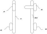
fig. 5 is a schematic diagram of another alternative configurations of the terminal and the second terminal of the wireless headset shown in fig. 1 and 2;
fig. 6 is a schematic structural diagram of an alternative structure of the -th connector in the wireless headset shown in fig. 1 and 2.
Detailed Description
In order to make the objects, technical solutions and advantages of the present invention more apparent, the present invention will be described in further with reference to the accompanying drawings and examples.
Moreover, the terms "comprises" and "comprising," and any variations thereof, are intended to cover a non-exclusive inclusion, such that a process, method, system, article, or apparatus that comprises a series of steps or elements is not limited to the listed steps or elements, but may alternatively include other steps or elements not expressly listed or inherent to such process, method, article, or apparatus.
The appearances of the phrase in various places in the specification are not necessarily all referring to the same embodiment, nor are separate or alternative embodiments mutually exclusive of other embodiments.
The wireless headset will be described in detail with reference to the accompanying drawings. In the use state, the sound source of the wireless headset is an electronic device having a wireless communication function. Electronic devices include, but are not limited to, computers, remote servers, handheld devices, smart phones, in-vehicle devices, wearable devices, or other wireless audio devices. The wireless headset may establish wireless communication with the electronic device, typically using a bluetooth wireless communication protocol to establish a communication link therebetween.
The specific structure of the wireless headset 100 is shown in the block diagram of fig. 1. the wireless headset 100 includes a headset housing 11. it is needless to say that the wireless headset 100 may be a bluetooth headset with a single ear or a TWS wireless headset 100, and the wearing manner thereof may be an in-ear type or a non-in-ear type, and the appearance structure of the headset housing 11 is not the improvement focus of the present invention, so the industrial appearance design of the headset housing is not further described in step .
The wireless headset 100 is further specially designed with a plurality of components of a connector 13, a terminal 15, a second terminal 22 and a antenna unit 20, different from the prior art, the th antenna unit 20 is a separate component which is arranged independently of the headset housing 11, wherein a th antenna loop 21 is arranged, the th antenna unit 20 and the main control chip 12 are detachably connected through a matching structure of a th connector 13, a th terminal 15 and the second terminal 22, wherein the th connector 13 is arranged in the headset housing 11, the th connector 13 is electrically connected with the main control chip 12, the 9 contact 14 of the th connector 13 is formed on an inner wall 10-1 of the headset housing 11, the th terminal 15 is arranged corresponding to the contacts, the th terminal 15 is formed on an outer wall 10-2 of the headset housing 11 and is electrically connected with the th contact 14, the corresponding to the th terminal 20 is arranged on an outer wall of the headset housing 11, the second terminal 20 is arranged on the corresponding to the second terminal 4620, and the second antenna loop 20 is arranged on the outer wall of the headset housing 11, so that the second antenna loop 20 can be effectively interfered with the user when the signal 4620 is arranged on the external of the headset housing 20, the second terminal 465, the second antenna loop 21 can be effectively improved.
Specifically, as shown in fig. 2, a second antenna unit 16 is further disposed in the earphone housing 11, a second antenna loop (not shown in the figure) is disposed in the second antenna unit 16, in order to select the th antenna unit 20 or the second antenna unit 16 according to different use requirements, a switching unit 17 is further disposed in the earphone housing 11, the switching unit 17 may be implemented by single-pole double-throw switches, or by other circuits that can implement the same function, when the terminal 15 of the 1 and the terminal 22 are connected and conducted, the switching unit 17 gates a signal path between the main control chip 12 and the connector 13 of the , the antenna unit 20 of the is configured as an external antenna of the wireless earphone 100, when the terminal 15 of the and the terminal 22 are disconnected, the switching unit 17 gates a signal path between the main control chip 12 and the second antenna unit 16, the antenna unit 16 is configured as a signal path between the wireless earphone 100 and the main control chip 12, when the terminal 15 of the second antenna unit 100 and the terminal 22 are disconnected, the main control chip 12 and the main control unit 12 is switched to the external antenna 12, the main control chip 12 is automatically, when the wireless earphone 100 is switched to the external antenna 12, the wireless earphone 12 is connected and the main control unit 12, the wireless earphone 12 is switched to the external antenna 12, the wireless earphone can be switched to the wireless earphone 12, the wireless earphone can be automatically, the wireless earphone can be switched to the wireless earphone 12, the wireless earphone can be switched to the wireless earphone 12, the wireless earphone can be switched to the wireless earphone 12, the wireless earphone.
As shown in fig. 3 to 5, various matching structures between the th terminal 15 and the second terminal 22 are provided, the th terminal 15 is disposed at a position corresponding to the th contact 14 and is conducted with each other through an LDS laser etching process, the second terminal 22 is preferably disposed at a position corresponding to the feed point of the th antenna loop 21, and is also conducted with each other through the LDS laser etching process, as shown in fig. 3, in the embodiment, the th terminal 15 is a th snap 31 extending outward along the outer wall of the earphone housing 11, and the second terminal 22 is a second snap 33 extending outward along the outer wall of the support housing 20-0, wherein limit bumps 32 are disposed on the th snap 31, limit bumps 34 matching with the limit bumps 32 are disposed on the second snap 33, when the th snap 31 and the second snap 33 are connected, the limit bumps 34 extend into the limit bumps 32, the th terminal 15 and the second terminal 22 are connected to the limit bumps matched with the limit card slot 32, when the switch signal transmission between the switch between the limit bumps 3884, the switch signal output of the limit bumps is detected by the switch between the switch unit, and the switch between the switch of the switch bump switch between the limit bumps.
As shown in FIG. 4, in another alternative design, the catch is designed as a catch 35 extending from bottom to top, and the second catch is designed as a second catch 36 extending from top to bottom. when the catch and the second catch are connected, the catch 35 and the second catch 36 catch, respectively, so as to ensure the stability of the circuit connection, the antenna unit 20 can be prevented from falling.
In the design of fig. 3 and 4, the th antenna unit 20 can be easily worn on the earphone housing 11 by the th snap and the second snap.
The th terminal 15 and the second terminal 22 can also adopt the design as shown in fig. 5, wherein the th terminal 15 is a metal patch 41 such as copper exposed or copper column disposed on the outer wall of the earphone housing 11, the second terminal 22 is a metal probe 42 extending outward along the outer wall of the support housing 20-0, when the metal probe 42 contacts with the metal patch 41, the th terminal 15 and the second terminal 22 are connected and conducted, in order to keep the contact between the metal patch 41 and the metal probe 42 stable, the th magnetic attraction part 43 is disposed on the earphone housing 11 below the metal patch 41, the support housing 20-0 below the metal probe 42 is disposed with a corresponding second magnetic attraction part 44, the th magnetic attraction part 43 and the second magnetic attraction part 44 have opposite magnetism, when the th magnetic attraction part 43 and the second magnetic attraction part 44 attract each other, the metal probe 42 contacts with the metal patch 41 and keeps stable contact.
In the present invention, the -th connector 13 may be a metal probe or antenna clip, the bottom of which is soldered to the signal wires on the PCBA and the top of which forms the -th contact 14 on the inner wall of the headphone housing 11.
Through tests, the wireless earphone provided by the invention has a very good effect on preventing the jamming, and specific experimental results are shown in the experimental data in tables 1 to 3.

TABLE 1
| Environment of use | Railway station | Crowded elevator | Crowded subway | Strong signal source |
| Common wireless earphone | Extremely block | Light and micro calorie dun | Severe calking | Light and micro calorie dun |
| The invention | Light and micro calorie dun | Without clamping | Without clamping | Without clamping |
TABLE 2

TABLE 3
In the above embodiments, the descriptions of the respective embodiments have respective emphasis, and for parts that are not described in detail in a certain embodiment, reference may be made to related descriptions of other embodiments.
For example, the above-described embodiments of the apparatus are merely illustrative, such as the division of the above-described units or modules into only logical functional divisions, and other divisions may be possible in practice, such as multiple units or components may be combined or integrated into another systems, or features may be omitted or not implemented.
The units described as separate parts may or may not be physically separate, and parts displayed as units may or may not be physical units, that is, may be located in physical spaces, or may also be distributed on multiple network units, and some or all of the units may be selected according to actual needs to achieve the purpose of the embodiment.
In addition, the functional units in the embodiments of the present application may be integrated into processing units, or each unit may exist alone physically, or two or more units are integrated into units.
The above examples are only intended to illustrate the technical solution of the present invention, but not to limit it; although the present invention has been described in detail with reference to the foregoing embodiments, it will be apparent to those skilled in the art that various changes may be made and equivalents may be substituted for elements thereof; and such modifications or substitutions do not depart from the spirit and scope of the corresponding technical solutions.
Claims (10)
- The wireless earphones of 1 and kinds comprise earphone shells, wherein the earphone shells are provided with a main control chip, and the wireless earphones are characterized by further comprising:an th connector, the th connector electrically connected to the main control chip, having:an th contact, the th contact being formed on an inner wall of the earphone house;an th terminal, the th terminal being formed on an outer wall of the earphone housing and being in conduction with the th contact;an th antenna element, the th antenna element being disposed independently of the earphone body, the th antenna element having a th antenna loop disposed therein, anda second terminal formed on an outer wall of the th antenna element and in conductive communication with the th antenna loop;when the th terminal and the second terminal are connected to be conductive, the th antenna unit is configured as an external antenna of the wireless headset.
- 2. The wireless headset of claim 1, further comprising:the second antenna unit is arranged in the earphone shell and is internally provided with a second antenna loop; anda switching unit disposed in the earphone housing;when the th terminal and the second terminal are connected and conducted, the switching unit gates a signal path between the main control chip and the th connector, the th antenna unit is configured as an external antenna of the wireless headset, and when the th terminal and the second terminal are disconnected, the switching unit gates a signal path between the main control chip and the second antenna unit, and the second antenna unit is configured as an internal antenna of the wireless headset.
- 3. The wireless headset of claim 2,the th antenna element further comprising:and the th antenna loop is wound and pasted on the inner wall of the supporting shell.
- 4. The wireless headset of claim 3,the th terminal is a th buckle which extends outwards along the outer wall of the earphone shell;the second terminal is a second buckle which extends outwards along the outer wall of the supporting shell;when the th buckle and the second buckle are buckled and connected, the th terminal and the second terminal are connected and conducted.
- 5. The wireless headset of claim 4,the th buckle is provided with at least limiting clamping grooves, the second buckle is provided with at least limiting bulges matched with the limiting clamping grooves, and when the th buckle and the second buckle are buckled and connected, the limiting bulges extend into the limiting clamping grooves.
- 6. The wireless headset of claim 4,the th buckle comprises a th hook extending from bottom to top, the second buckle comprises a second hook extending from top to bottom, and when the th buckle and the second buckle are buckled and connected, the th hook and the second hook are buckled up and down.
- 7. The wireless headset of claim 3,the th terminal is a metal patch arranged on the outer wall of the earphone shell;the second terminal is a metal probe which extends outwards along the outer wall of the supporting shell;when the metal probe is contacted with the metal patch, the th terminal and the second terminal are connected and conducted.
- 8. The wireless headset of claim 7, further comprising:a th magnetic attraction part, the th magnetic attraction part is arranged on the earphone shell, andthe second magnetic attraction part is arranged on the supporting shell;the magnetic attraction part and the second magnetic attraction part are opposite in magnetism, and when the magnetic attraction part and the second magnetic attraction part attract each other, the metal probe is in contact with the metal patch.
- 9. The wireless headset of any one of claims 1-8 to , wherein the terminal is in electrical communication with the contact via LDS radium etching, and the second terminal is in electrical communication with the antenna loop via LDS radium etching.
- 10. The wireless headset of claim 9, wherein the -th connector is a metal probe or antenna clip.
Priority Applications (1)
| Application Number | Priority Date | Filing Date | Title |
|---|---|---|---|
| CN201910995484.0A CN110740399B (en) | 2019-10-18 | 2019-10-18 | Wireless earphone |
Applications Claiming Priority (1)
| Application Number | Priority Date | Filing Date | Title |
|---|---|---|---|
| CN201910995484.0A CN110740399B (en) | 2019-10-18 | 2019-10-18 | Wireless earphone |
Publications (2)
| Publication Number | Publication Date |
|---|---|
| CN110740399A true CN110740399A (en) | 2020-01-31 |
| CN110740399B CN110740399B (en) | 2021-06-11 |
Family
ID=69270218
Family Applications (1)
| Application Number | Title | Priority Date | Filing Date |
|---|---|---|---|
| CN201910995484.0A Active CN110740399B (en) | 2019-10-18 | 2019-10-18 | Wireless earphone |
Country Status (1)
| Country | Link |
|---|---|
| CN (1) | CN110740399B (en) |
Cited By (2)
| Publication number | Priority date | Publication date | Assignee | Title |
|---|---|---|---|---|
| CN113115165A (en) * | 2021-05-28 | 2021-07-13 | 立讯电子科技(昆山)有限公司 | Dual-communication-mode earphone |
| WO2023125727A1 (en) * | 2021-12-31 | 2023-07-06 | 华为技术有限公司 | Earphone, assembling jig, and earphone manufacturing method |
Citations (8)
| Publication number | Priority date | Publication date | Assignee | Title |
|---|---|---|---|---|
| CN105337052A (en) * | 2015-11-28 | 2016-02-17 | 广东欧珀移动通信有限公司 | Antenna device of mobile terminal and mobile terminal |
| CN105375117A (en) * | 2015-11-28 | 2016-03-02 | 广东欧珀移动通信有限公司 | Antenna device of mobile terminal and mobile terminal |
| CN105846050A (en) * | 2015-02-02 | 2016-08-10 | 三星电子株式会社 | Antenna and electronic device having the same |
| CN105872133A (en) * | 2015-12-16 | 2016-08-17 | 乐视移动智能信息技术(北京)有限公司 | Mobile terminal and external antenna |
| CN106842896A (en) * | 2016-12-26 | 2017-06-13 | 歌尔股份有限公司 | A kind of method of controlling antenna of wearable device, shell and wearable device |
| CN109149081A (en) * | 2018-07-17 | 2019-01-04 | 奇酷互联网络科技(深圳)有限公司 | external antenna device and terminal |
| CN109151645A (en) * | 2018-09-26 | 2019-01-04 | 广东全过程工程咨询有限公司 | The wireless telecom equipment of variable device |
| CN109417220A (en) * | 2016-07-27 | 2019-03-01 | 英特尔公司 | The wearable electronic supported with detachable type antenna |
-
2019
- 2019-10-18 CN CN201910995484.0A patent/CN110740399B/en active Active
Patent Citations (8)
| Publication number | Priority date | Publication date | Assignee | Title |
|---|---|---|---|---|
| CN105846050A (en) * | 2015-02-02 | 2016-08-10 | 三星电子株式会社 | Antenna and electronic device having the same |
| CN105337052A (en) * | 2015-11-28 | 2016-02-17 | 广东欧珀移动通信有限公司 | Antenna device of mobile terminal and mobile terminal |
| CN105375117A (en) * | 2015-11-28 | 2016-03-02 | 广东欧珀移动通信有限公司 | Antenna device of mobile terminal and mobile terminal |
| CN105872133A (en) * | 2015-12-16 | 2016-08-17 | 乐视移动智能信息技术(北京)有限公司 | Mobile terminal and external antenna |
| CN109417220A (en) * | 2016-07-27 | 2019-03-01 | 英特尔公司 | The wearable electronic supported with detachable type antenna |
| CN106842896A (en) * | 2016-12-26 | 2017-06-13 | 歌尔股份有限公司 | A kind of method of controlling antenna of wearable device, shell and wearable device |
| CN109149081A (en) * | 2018-07-17 | 2019-01-04 | 奇酷互联网络科技(深圳)有限公司 | external antenna device and terminal |
| CN109151645A (en) * | 2018-09-26 | 2019-01-04 | 广东全过程工程咨询有限公司 | The wireless telecom equipment of variable device |
Cited By (2)
| Publication number | Priority date | Publication date | Assignee | Title |
|---|---|---|---|---|
| CN113115165A (en) * | 2021-05-28 | 2021-07-13 | 立讯电子科技(昆山)有限公司 | Dual-communication-mode earphone |
| WO2023125727A1 (en) * | 2021-12-31 | 2023-07-06 | 华为技术有限公司 | Earphone, assembling jig, and earphone manufacturing method |
Also Published As
| Publication number | Publication date |
|---|---|
| CN110740399B (en) | 2021-06-11 |
Similar Documents
| Publication | Publication Date | Title |
|---|---|---|
| AU2019200365B2 (en) | Case for a portable listening device | |
| WO2004068692A3 (en) | Low inductance electrical contacts and lga connector system | |
| CN110740399A (en) | kinds of wireless earphone | |
| DK201970048A1 (en) | Case with inductive charging system to charge a portable device | |
| KR20050009116A (en) | Antenna apparatus for card having radio communication module |
Legal Events
| Date | Code | Title | Description |
|---|---|---|---|
| PB01 | Publication | ||
| PB01 | Publication | ||
| SE01 | Entry into force of request for substantive examination | ||
| SE01 | Entry into force of request for substantive examination | ||
| GR01 | Patent grant | ||
| GR01 | Patent grant |