CN110739626B - Heat dissipation electric power cabinet for electric power engineering - Google Patents
Heat dissipation electric power cabinet for electric power engineering Download PDFInfo
- Publication number
- CN110739626B CN110739626B CN201911174940.1A CN201911174940A CN110739626B CN 110739626 B CN110739626 B CN 110739626B CN 201911174940 A CN201911174940 A CN 201911174940A CN 110739626 B CN110739626 B CN 110739626B
- Authority
- CN
- China
- Prior art keywords
- heat dissipation
- electric power
- cabinet body
- cabinet
- water
- Prior art date
- Legal status (The legal status is an assumption and is not a legal conclusion. Google has not performed a legal analysis and makes no representation as to the accuracy of the status listed.)
- Active
Links
Images


Classifications
-
- H—ELECTRICITY
- H02—GENERATION; CONVERSION OR DISTRIBUTION OF ELECTRIC POWER
- H02B—BOARDS, SUBSTATIONS OR SWITCHING ARRANGEMENTS FOR THE SUPPLY OR DISTRIBUTION OF ELECTRIC POWER
- H02B1/00—Frameworks, boards, panels, desks, casings; Details of substations or switching arrangements
- H02B1/56—Cooling; Ventilation
- H02B1/565—Cooling; Ventilation for cabinets
Abstract
The invention relates to the technical field of electric power correlation, in particular to a heat dissipation electric power cabinet for electric power engineering, which comprises a cabinet body; articulated on the cabinet body have the dodge gate, be provided with retaining mechanism on the cabinet body, retaining mechanism passes through the control valve body intercommunication with the water-cooling mechanism who sets up on the cabinet body, the side of the cabinet body still is provided with extends the chamber, and the inboard that extends the chamber is provided with the induced air subassembly, extend the chamber with be provided with shutter assembly between the cabinet body, shutter assembly pass through link assembly with control valve body connects, works as induced air subassembly during operation, shutter assembly opens and drives through link assembly under the wind-force effect control valve body opens in order to realize water in the retaining mechanism enters into in the water-cooling mechanism. The invention has novel design, realizes the opening of the shutter assembly and then carries out air cooling heat dissipation through the work of the induced air assembly, can automatically open the control valve body to match with water cooling heat dissipation, and has good heat dissipation effect and strong practicability.
Description
Technical Field
The invention relates to the technical field of electric power correlation, in particular to a heat dissipation electric power cabinet for electric power engineering.
Background
Electric power engineering (electric power engineering), i.e. engineering related to the production, transportation, distribution of electric energy, also broadly includes engineering of electricity as a power and energy source for applications in various fields. Meanwhile, the method can be understood to the transmission and transformation business expansion project.
After the 20 th century, the production of electric energy was mainly dependent on thermal power plants, hydroelectric power plants and nuclear power plants. The conditioned place also uses tidal, geothermal and wind energy to generate electricity. The transmission and distribution of electric energy is mainly realized by high-voltage and low-voltage alternating current power networks.
At the job site, generally need use the electric power cabinet to realize the control of each operating device, nevertheless because general electric power cabinet all places in the external world, under the shining of sun, and electric elements's work heat production in the electric power cabinet, lead to the electric power cabinet in the temperature higher, have the potential safety hazard.
In order to solve the problem, a fan is generally and directly added to the existing electric power cabinet to dissipate heat, but the heat dissipation effect is poor.
Disclosure of Invention
The invention aims to provide a heat dissipation power cabinet for power engineering, which aims to solve the problems in the background technology.
In order to achieve the purpose, the invention provides the following technical scheme:
a heat dissipation power cabinet for power engineering comprises a cabinet body; articulated on the cabinet body have the dodge gate, be provided with retaining mechanism on the cabinet body, retaining mechanism passes through the control valve body intercommunication with the water-cooling mechanism who sets up on the cabinet body, the side of the cabinet body still is provided with extends the chamber, and the inboard that extends the chamber is provided with the induced air subassembly, extend the chamber with be provided with shutter assembly between the cabinet body, shutter assembly pass through link assembly with control valve body connects, works as induced air subassembly during operation, shutter assembly opens and drives through link assembly under the wind-force effect control valve body opens in order to realize water in the retaining mechanism enters into in the water-cooling mechanism.
As a further scheme of the invention: the water storage mechanism comprises a water storage cavity arranged on the cabinet body, a conical top is arranged at the upper end of the water storage cavity, and the area of one side of the conical top close to the water storage cavity is smaller than the horizontal area of the water storage cavity.
As a still further scheme of the invention: the water-cooling heat dissipation mechanism comprises a drain pipe arranged on the cabinet body and a heat dissipation flow channel embedded in the side wall of the cabinet body, the drain pipe is communicated with the heat dissipation flow channel through a guide pipe, and the drain pipe is communicated with the water storage cavity through a control valve body.
As a still further scheme of the invention: the control valve body comprises a control pipe which is arranged at the lower end of the water storage cavity and communicated with the water discharge pipe, a partition plate is arranged on the inner side of the control pipe, a through hole for the push rod to penetrate through is formed in the partition plate, and a through groove is formed in the push rod.
As a still further scheme of the invention: the induced air subassembly is including installing extend the fan of intracavity, the position department that is used for installing the fan on extending the chamber is provided with a plurality of inlet ports, and installs the filter screen in the inlet port.
As a still further scheme of the invention: the shutter plate assembly comprises a plurality of shutter plates which are sequentially arranged from top to bottom, and every two adjacent shutter plates are connected through a connecting rod.
As a still further scheme of the invention: the connecting rod assembly comprises a fixed block fixed on the louver board, and the fixed block is hinged to one end, far away from the control tube, of the pushing rod through a movable rod hinged to the fixed block.
As a still further scheme of the invention: the inboard demountable installation of the cabinet body has the mounting panel, and the mounting panel is used for electric component's fixed, the front and back end of mounting panel not with the inner wall contact of the cabinet body.
Compared with the prior art, the invention has the beneficial effects that: the invention has novel design, realizes the opening of the shutter assembly and then carries out air cooling heat dissipation through the work of the induced air assembly, can automatically open the control valve body to match with water cooling heat dissipation, and has good heat dissipation effect and strong practicability.
Drawings
Fig. 1 is a front view of a heat dissipation power cabinet for power engineering.
Fig. 2 is a sectional view of a heat dissipation power cabinet for power engineering.
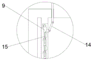
Fig. 3 is an enlarged view of a structure at a in fig. 2.
Fig. 4 is an enlarged view of the structure at B in fig. 2.
In the figure: 1-cabinet body, 2-movable door, 3-conical top, 4-water storage cavity, 5-drainage pipe, 6-mounting plate, 7-extension cavity, 8-blower, 9-louver board, 10-control pipe, 11-push rod, 12-clapboard, 13-through groove, 14-movable rod and 15-connecting rod.
Detailed Description
The technical solutions in the embodiments of the present invention will be clearly and completely described below with reference to the drawings in the embodiments of the present invention, and it is obvious that the described embodiments are only a part of the embodiments of the present invention, and not all of the embodiments. All other embodiments, which can be derived by a person skilled in the art from the embodiments given herein without making any creative effort, shall fall within the protection scope of the present invention.
Referring to fig. 1 to 4, in an embodiment of the present invention, a heat dissipation power cabinet for power engineering includes a cabinet body 1; articulated have dodge gate 2 on the cabinet body 1, the setting of dodge gate 2 can make things convenient for the installation and the maintenance of the internal electrical component of cabinet 1, be provided with the retaining mechanism on the cabinet body 1, retaining mechanism passes through the control valve body intercommunication with the water-cooling heat dissipation mechanism who sets up on the cabinet body 1, the side of the cabinet body 1 still is provided with extends chamber 7, and the inboard that extends chamber 7 is provided with the induced air subassembly, extend chamber 7 with be provided with the shutter plate subassembly between the cabinet body 1, shutter plate subassembly pass through link assembly with control valve body connects, works as the induced air subassembly during operation, shutter plate subassembly is opened and is passed through link assembly drive under the wind-force effect control valve body opens in order to realize water in the retaining mechanism enters into water-cooling heat dissipation mechanism, realizes water-cooling heat dissipation.
In the embodiment of the invention, the cabinet body 1 is further provided with a temperature sensor, the temperature sensor is electrically connected with the air inducing assembly, and when the external temperature is higher than the set value of the temperature sensor, the air inducing assembly works to realize heat dissipation.
In the embodiment of the present invention, it can be understood that the induced air assembly is electrically connected to a power supply mechanism, the power supply mechanism is used for providing an electric support for the operation of the induced air assembly, preferably, the power supply mechanism may adopt a storage battery, and a solar panel may be disposed at a side end of the cabinet body 1, so as to realize radio-television conversion and solve the problem of using commercial power.
In the embodiment of the invention, the louver board assembly is opened and then air-cooled heat dissipation is carried out through the work of the air inducing assembly, and meanwhile, the control valve body can be automatically opened to match with water-cooled heat dissipation, so that the heat dissipation effect is good, and the practicability is high.
As an embodiment of the invention, the water storage mechanism comprises a water storage cavity 4 arranged on the cabinet body 1, a conical top 3 is arranged at the upper end of the water storage cavity 4, and the area of one side of the conical top 3 close to the water storage cavity 4 is smaller than the horizontal area of the water storage cavity 4.
In the embodiment of the invention, the arranged conical top 3 can be used for collecting rainwater into the water storage cavity 4, and it can be understood that a through hole communicated with the inside of the water storage cavity 4 is arranged at a position where the water storage cavity 4 is not in contact with the conical top 3, and the rainwater enters the water storage cavity 4 through the through hole, so that the rainwater is collected.
As an embodiment of the present invention, the water-cooling heat dissipation mechanism includes a drain pipe 5 installed on the cabinet 1, and a heat dissipation channel embedded in a side wall of the cabinet 1, the drain pipe 5 is communicated with the heat dissipation channel through a conduit, and the drain pipe 5 is communicated with the water storage cavity 4 through a control valve.
In the embodiment of the invention, when the control valve body is opened, water in the water storage cavity 4 enters the water discharge pipe 5, and the water in the water discharge pipe 5 enters the heat dissipation flow channel through the guide pipe and is discharged through the heat dissipation flow channel, so that a better heat dissipation effect is achieved by matching with air cooling heat dissipation.
In the embodiment of the invention, the drain pipes 5 are wound around the outer wall of the cabinet body 1, and a plurality of heat dissipation flow channels are uniformly distributed on the cabinet body 1.
As an embodiment of the present invention, the control valve body includes a control pipe 10 installed at the lower end of the water storage cavity 4 and communicated with the drain pipe 5, a partition plate 12 is disposed inside the control pipe 10, a through hole for the push rod 11 to pass through is disposed on the partition plate 12, a through groove 13 is disposed on the push rod 11, and when the through groove 13 on the push rod 11 is communicated with two sides of the partition plate 12, water in the water storage cavity 4 can enter the drain pipe 5.
In the embodiment of the invention, an extension plate matched with the embedded groove on the partition plate 12 is fixed at the upper end of the push rod 11, and the extension plate and the embedded groove are matched to play a sealing role.
As an embodiment of the present invention, the induced draft assembly includes a fan 8 installed in the extension chamber 7, a plurality of air inlets are disposed at positions on the extension chamber 7 for installing the fan 8, and a filter screen is installed in the air inlets.
In the embodiment of the invention, when the fan 8 works, the outside air is introduced into the extension cavity 7 through the air inlet hole, and the arranged filter screen plays a dustproof role.
As an embodiment of the invention, the louver assembly comprises a plurality of louvers 9 which are sequentially arranged from top to bottom, and two adjacent louvers 9 are connected through a connecting rod 15, so that the louvers 9 can rotate simultaneously under the action of wind power.
In the embodiment of the present invention, both ends of the connecting rod 15 are rotatably connected to the two louvers 9, respectively, and the louvers 9 are inclined in an initial state in order to reduce power required for rotating the louvers 9.
As an embodiment of the present invention, the connecting rod assembly includes a fixed block fixed on the louver board 9, the fixed block is hinged to one end of the pushing rod 11 far away from the control tube 10 through a movable rod 14 hinged to the fixed block, and when the louver board 9 rotates upward, the pushing rod 11 is driven to move upward through the action of the movable rod 14, so as to open the control valve.
As an embodiment of the present invention, an installation plate 6 is detachably installed on the inner side of the cabinet 1, the installation plate 6 is used for fixing an electrical component, and the front end and the rear end of the installation plate 6 are not in contact with the inner wall of the cabinet 1, so that a gas flowing space is reserved, and a heat dissipation effect is ensured.
In the embodiment of the present invention, the mounting plate 6 is fixed to the inner wall of the cabinet 1 by bolts.
It will be evident to those skilled in the art that the invention is not limited to the details of the foregoing illustrative embodiments, and that the present invention may be embodied in other specific forms without departing from the spirit or essential attributes thereof. The present embodiments are therefore to be considered in all respects as illustrative and not restrictive, the scope of the invention being indicated by the appended claims rather than by the foregoing description, and all changes which come within the meaning and range of equivalency of the claims are therefore intended to be embraced therein. Any reference sign in a claim should not be construed as limiting the claim concerned.
Furthermore, it should be understood that although the present description refers to embodiments, not every embodiment may contain only a single embodiment, and such description is for clarity only, and those skilled in the art should integrate the description, and the embodiments may be combined as appropriate to form other embodiments understood by those skilled in the art.
Claims (8)
1. A heat dissipation power cabinet for power engineering comprises a cabinet body (1); articulated have dodge gate (2) on the cabinet body (1), be provided with retaining mechanism on the cabinet body (1), retaining mechanism passes through the control valve body intercommunication with the water-cooling heat dissipation mechanism who sets up on the cabinet body (1), its characterized in that, the side of the cabinet body (1) still is provided with extends chamber (7), and the inboard that extends chamber (7) is provided with the induced air subassembly, extend chamber (7) with be provided with shutter assembly between the cabinet body (1), shutter assembly pass through link assembly with control valve body connects, works as the induced air subassembly during operation, shutter assembly opens and drives through link assembly under the wind-force effect control valve body opens in order to realize water in the retaining mechanism enters into in the water-cooling heat dissipation mechanism.
2. The heat dissipation electric power cabinet for electric power engineering according to claim 1, wherein the water storage mechanism comprises a water storage cavity (4) mounted on the cabinet body (1), a conical top (3) is mounted at the upper end of the water storage cavity (4), and the area of one side of the conical top (3) close to the water storage cavity (4) is smaller than the horizontal area of the water storage cavity (4).
3. The heat dissipation electric power cabinet for electric power engineering according to claim 2, wherein the water-cooled heat dissipation mechanism comprises a drain pipe (5) mounted on the cabinet body (1), and a heat dissipation flow channel embedded in the side wall of the cabinet body (1), the drain pipe (5) is communicated with the heat dissipation flow channel through a conduit, and the drain pipe (5) is communicated with the water storage cavity (4) through a control valve body.
4. The heat dissipation electric power cabinet for electric power engineering according to claim 3, wherein the control valve body comprises a control pipe (10) installed at the lower end of the water storage cavity (4) and communicated with the water discharge pipe (5), a partition plate (12) is arranged on the inner side of the control pipe (10), a through hole for a push rod (11) to penetrate through is arranged on the partition plate (12), and a through groove (13) is arranged on the push rod (11).
5. The heat dissipation electric power cabinet for electric power engineering according to claim 1, wherein the induced air assembly comprises a fan (8) installed in the extension cavity (7), a plurality of air inlets are provided on the extension cavity (7) at positions for installing the fan (8), and a filter screen is installed in the air inlets.
6. The heat dissipation electric power cabinet for electric power engineering according to claim 1, wherein the louver assembly comprises a plurality of louvers (9) arranged from top to bottom, and two adjacent louvers (9) are connected by a connecting rod (15).
7. The heat dissipation electric power cabinet for electric power engineering according to claim 4, characterized in that the connecting rod assembly comprises a fixed block fixed on the louver board (9), and the fixed block is hinged to one end of the pushing rod (11) far away from the control tube (10) through a movable rod (14) hinged to the fixed block.
8. The heat dissipation electric power cabinet for electric power engineering according to claim 1, wherein a mounting plate (6) is detachably mounted on the inner side of the cabinet body (1), the mounting plate (6) is used for fixing electric components, and the front end and the rear end of the mounting plate (6) are not in contact with the inner wall of the cabinet body (1).
Priority Applications (1)
| Application Number | Priority Date | Filing Date | Title |
|---|---|---|---|
| CN201911174940.1A CN110739626B (en) | 2019-11-26 | 2019-11-26 | Heat dissipation electric power cabinet for electric power engineering |
Applications Claiming Priority (1)
| Application Number | Priority Date | Filing Date | Title |
|---|---|---|---|
| CN201911174940.1A CN110739626B (en) | 2019-11-26 | 2019-11-26 | Heat dissipation electric power cabinet for electric power engineering |
Publications (2)
| Publication Number | Publication Date |
|---|---|
| CN110739626A CN110739626A (en) | 2020-01-31 |
| CN110739626B true CN110739626B (en) | 2021-07-20 |
Family
ID=69273792
Family Applications (1)
| Application Number | Title | Priority Date | Filing Date |
|---|---|---|---|
| CN201911174940.1A Active CN110739626B (en) | 2019-11-26 | 2019-11-26 | Heat dissipation electric power cabinet for electric power engineering |
Country Status (1)
| Country | Link |
|---|---|
| CN (1) | CN110739626B (en) |
Families Citing this family (1)
| Publication number | Priority date | Publication date | Assignee | Title |
|---|---|---|---|---|
| CN115085068B (en) * | 2022-08-22 | 2022-10-25 | 广东金晖隆开关有限公司 | High-safety switch cabinet |
Family Cites Families (4)
| Publication number | Priority date | Publication date | Assignee | Title |
|---|---|---|---|---|
| CN203983792U (en) * | 2014-07-04 | 2014-12-03 | 国家电网公司 | A kind of novel quick heat radiating low-voltage comprehensive distribution box |
| CN105356333A (en) * | 2015-10-22 | 2016-02-24 | 国网浙江平湖市供电公司 | DC power box |
| CN107017569B (en) * | 2017-04-10 | 2023-08-01 | 国网浙江台州市路桥区供电公司 | Intelligent dehumidification system for high-voltage switch cabinet |
| CN207945094U (en) * | 2017-12-29 | 2018-10-09 | 绍兴市上虞区兴荣风机有限公司 | A kind of rectangular wall type axial-flow fan |
-
2019
- 2019-11-26 CN CN201911174940.1A patent/CN110739626B/en active Active
Also Published As
| Publication number | Publication date |
|---|---|
| CN110739626A (en) | 2020-01-31 |
Similar Documents
| Publication | Publication Date | Title |
|---|---|---|
| CN210468539U (en) | Indoor ventilation system of transformer substation | |
| CN204793764U (en) | Water cooling circulation's box -type substation | |
| CN110739626B (en) | Heat dissipation electric power cabinet for electric power engineering | |
| CN210465510U (en) | Ammeter case with heat abstractor | |
| CN213071925U (en) | Multiple radiating intelligent box-type substation | |
| CN210838484U (en) | High-low voltage switch cabinet with good heat dissipation effect | |
| CN111834944B (en) | Box-type substation cooling system | |
| CN219779562U (en) | Natural strong-exhaust radiating box-type substation | |
| CN210926839U (en) | Box-type substation | |
| CN216981322U (en) | Box-type substation convenient for heat dissipation | |
| CN216016229U (en) | Cooling equipment for multifunctional intelligent box-type substation | |
| CN215817214U (en) | Cooling equipment for box-type substation | |
| CN201750060U (en) | Box-type substation box body | |
| CN212695471U (en) | Dustproof heat dissipation direct current screen | |
| CN203352007U (en) | Box-type photovoltaic inverter station structure using heat-pipe self-cooling heat radiation | |
| CN113889876A (en) | Intelligent solar photovoltaic box-type substation | |
| CN111106536A (en) | Protection device for electrical equipment with high-efficient heat dissipation | |
| CN218386272U (en) | Integrated heat dissipation distribution box | |
| CN213989687U (en) | High-heat-dissipation energy-saving power distribution cabinet shell | |
| CN214958270U (en) | Box-type substation that new forms of energy utilized | |
| CN220570153U (en) | Block terminal convenient to safety control | |
| CN213692877U (en) | Heat dissipation type electromechanical control cabinet | |
| CN215497866U (en) | Novel fire prevention high temperature resistant distribution control equipment | |
| CN219041201U (en) | Waterproof heat dissipation type outdoor distribution box | |
| CN220475152U (en) | Transformer case with heat dissipation wind channel |
Legal Events
| Date | Code | Title | Description |
|---|---|---|---|
| PB01 | Publication | ||
| PB01 | Publication | ||
| SE01 | Entry into force of request for substantive examination | ||
| SE01 | Entry into force of request for substantive examination | ||
| GR01 | Patent grant | ||
| GR01 | Patent grant |