CN110723710A - Liquid composite spring push-pull type vacuum liquid injection machine and liquid injection method - Google Patents
Liquid composite spring push-pull type vacuum liquid injection machine and liquid injection method Download PDFInfo
- Publication number
- CN110723710A CN110723710A CN201810783260.9A CN201810783260A CN110723710A CN 110723710 A CN110723710 A CN 110723710A CN 201810783260 A CN201810783260 A CN 201810783260A CN 110723710 A CN110723710 A CN 110723710A
- Authority
- CN
- China
- Prior art keywords
- liquid
- gas
- electromagnetic valve
- vacuum pump
- vacuum
- Prior art date
- Legal status (The legal status is an assumption and is not a legal conclusion. Google has not performed a legal analysis and makes no representation as to the accuracy of the status listed.)
- Granted
Links
Images

Classifications
-
- B—PERFORMING OPERATIONS; TRANSPORTING
- B67—OPENING, CLOSING OR CLEANING BOTTLES, JARS OR SIMILAR CONTAINERS; LIQUID HANDLING
- B67D—DISPENSING, DELIVERING OR TRANSFERRING LIQUIDS, NOT OTHERWISE PROVIDED FOR
- B67D7/00—Apparatus or devices for transferring liquids from bulk storage containers or reservoirs into vehicles or into portable containers, e.g. for retail sale purposes
- B67D7/02—Apparatus or devices for transferring liquids from bulk storage containers or reservoirs into vehicles or into portable containers, e.g. for retail sale purposes for transferring liquids other than fuel or lubricants
-
- B—PERFORMING OPERATIONS; TRANSPORTING
- B67—OPENING, CLOSING OR CLEANING BOTTLES, JARS OR SIMILAR CONTAINERS; LIQUID HANDLING
- B67D—DISPENSING, DELIVERING OR TRANSFERRING LIQUIDS, NOT OTHERWISE PROVIDED FOR
- B67D7/00—Apparatus or devices for transferring liquids from bulk storage containers or reservoirs into vehicles or into portable containers, e.g. for retail sale purposes
- B67D7/06—Details or accessories
- B67D7/78—Arrangements of storage tanks, reservoirs or pipe-lines
-
- H—ELECTRICITY
- H01—ELECTRIC ELEMENTS
- H01M—PROCESSES OR MEANS, e.g. BATTERIES, FOR THE DIRECT CONVERSION OF CHEMICAL ENERGY INTO ELECTRICAL ENERGY
- H01M50/00—Constructional details or processes of manufacture of the non-active parts of electrochemical cells other than fuel cells, e.g. hybrid cells
- H01M50/60—Arrangements or processes for filling or topping-up with liquids; Arrangements or processes for draining liquids from casings
-
- Y—GENERAL TAGGING OF NEW TECHNOLOGICAL DEVELOPMENTS; GENERAL TAGGING OF CROSS-SECTIONAL TECHNOLOGIES SPANNING OVER SEVERAL SECTIONS OF THE IPC; TECHNICAL SUBJECTS COVERED BY FORMER USPC CROSS-REFERENCE ART COLLECTIONS [XRACs] AND DIGESTS
- Y02—TECHNOLOGIES OR APPLICATIONS FOR MITIGATION OR ADAPTATION AGAINST CLIMATE CHANGE
- Y02E—REDUCTION OF GREENHOUSE GAS [GHG] EMISSIONS, RELATED TO ENERGY GENERATION, TRANSMISSION OR DISTRIBUTION
- Y02E60/00—Enabling technologies; Technologies with a potential or indirect contribution to GHG emissions mitigation
- Y02E60/10—Energy storage using batteries
Landscapes
- Engineering & Computer Science (AREA)
- Mechanical Engineering (AREA)
- Chemical & Material Sciences (AREA)
- Chemical Kinetics & Catalysis (AREA)
- Electrochemistry (AREA)
- General Chemical & Material Sciences (AREA)
- Jet Pumps And Other Pumps (AREA)
Abstract
The invention discloses a liquid composite spring push-pull type vacuum liquid injection machine and a liquid injection method, wherein the liquid composite spring push-pull type vacuum liquid injection machine comprises a vacuum pump, a vacuum pump electromagnetic valve, a vacuumizing quick-change connector, an oil tank, a gas-liquid separator, a high-pressure water pump electromagnetic valve and a liquid discharge electromagnetic valve; the vacuum pump is connected with the gas-liquid separator, the gas-liquid separator is connected with the vacuum pump electromagnetic valve, and the vacuum pump electromagnetic valve is connected with the vacuumizing quick-change connector; the bottom of the gas-liquid separator is connected with a liquid discharge electromagnetic valve which is connected with an oil tank. The upper part in the gas-liquid separator is divided into two cavities which are respectively connected with a vacuum pump and a liquid composite spring, and when a medium is recovered, the medium is refluxed and separated by utilizing negative pressure and liquid gravity in a cavity separation mode, so that gas-liquid separation is realized. The invention can realize on-site liquid injection and on-site mobile inspection, realize liquid injection pressure maintaining and medium recovery, fully separate gas and liquid during medium recovery, prevent the medium from flowing into the vacuum pump and prevent the vacuum pump from being damaged.
Description
Technical Field
The invention relates to the technical field of vacuum liquid injection.
Background
The liquid composite spring vacuum liquid injection machine is operating equipment specially used for inspection and liquid injection of a liquid composite spring, and can realize liquid injection after vacuum and liquid return under negative pressure; the device can be provided with inspection equipment and maintenance equipment, is special equipment for on-site flowing liquid injection operation and inspection or maintenance operation, and is indispensable daily liquid injection, inspection and maintenance equipment. The existing vacuum liquid injection device has insufficient gas-liquid separation when a medium is recovered, and liquid is easy to flow back to a vacuum pump to cause faults, even cause the damage of the vacuum pump. The method also has some technical problems to be solved in the aspects of realizing on-site liquid injection and on-site mobile inspection, realizing liquid injection and pressure maintaining, medium recovery and the like.
Among the prior art, application number is CN 201620904045.6's utility model discloses a vacuum lithium cell electrolyte annotates liquid machine, including horizontal table, battery positioning die, lifter plate, middle storage jar, quantitative liquid injection ware, electrolyte storage bucket, notes liquid pump and evacuating device. The utility model discloses a liquid machine is annotated in vacuum for application number CN201520537974.3 mainly uses in ration notes liquid equipment field, and the key effect is that the heat dissipation is annotated in the vacuum, and the medium uses water as the main. Application number is CN 201620396827.3's utility model discloses a liquid machine is annotated in vacuum mainly is used in soft packet of lithium cell encapsulation equipment technical field. In the above prior art, gas-liquid separation is insufficient.
Disclosure of Invention
The invention aims to solve the technical problem of providing a liquid composite spring push-pull type vacuum liquid injection machine and a liquid injection method, which can realize sufficient gas-liquid separation when a medium is recovered.
The technical scheme of the invention is as follows: a liquid composite spring push-pull type vacuum liquid injection machine comprises a vacuum pump, a vacuum pump electromagnetic valve, a vacuumizing quick-change connector, an oil tank, a gas-liquid separator, a high-pressure water pump electromagnetic valve and a liquid discharge electromagnetic valve; the vacuum pump is connected with the gas-liquid separator through a pipeline, the gas-liquid separator is connected with the vacuum pump electromagnetic valve through a pipeline, and the vacuum pump electromagnetic valve is connected with the vacuumizing quick-change connector through a pipeline; the bottom of the gas-liquid separator is connected with a liquid discharge electromagnetic valve through a pipeline, and the liquid discharge electromagnetic valve is connected with an oil tank through a pipeline; the high-pressure water pump is connected with the oil tank through a pipeline, the high-pressure water pump electromagnetic valve is connected with the high-pressure water pump through a pipeline, and the vacuumizing quick-change connector is connected with the high-pressure water pump electromagnetic valve through a pipeline.
A first liquid level meter and an air filter are arranged on the oil tank; an oil absorption filter is arranged on a pipeline between the high-pressure water pump and the oil tank.
The liquid composite spring push-pull type vacuum liquid injection machine also comprises a motor connected with a high-pressure water pump, and a one-way valve and a high-pressure water pump electric contact pressure gauge are arranged on a pipeline between the high-pressure water pump and a high-pressure water pump electromagnetic valve; a second liquid level meter is arranged on the gas-liquid separator; an oil return filter is arranged on a pipeline between the liquid discharge electromagnetic valve and the oil tank; an electric contact vacuum pressure gauge is connected on a pipeline between the vacuum pump and the gas-liquid separator.
The liquid composite spring push-pull type vacuum liquid injection machine also comprises an electric cabinet; the vacuum pump, the gas-liquid separator, the motor, the high-pressure water pump, the vacuum pump electromagnetic valve, the high-pressure water pump electromagnetic valve, the liquid discharge electromagnetic valve, the liquid level meter I, the liquid level meter II, the high-pressure water pump electric contact pressure meter, the electric contact vacuum pressure meter, the one-way valve and the oil tank are all connected with the electric cabinet.
The liquid composite spring push-pull type vacuum liquid injection machine further comprises a frame and rollers arranged below the frame; the electric cabinet, the vacuum pump, the oil tank, the gas-liquid separator and the high-pressure water pump are all installed on the frame.
The gas-liquid separator is a closed container, a cavity partition plate is vertically arranged at the upper part in the gas-liquid separator, the upper part in the gas-liquid separator is divided into two cavities by the cavity partition plate, and the top edge and the side edge of the cavity partition plate are respectively and hermetically connected with the top surface and the side wall of the inner wall of the gas-liquid separator; the vacuum pump is connected with one cavity of the gas-liquid separator through a pipeline, and the electromagnetic valve of the vacuum pump is connected with the other cavity of the gas-liquid separator through a pipeline.
The height of the bottom edge of the cavity separation plate is matched with the size of negative pressure and the minimum unit flow of medium backflow, and the volume of a space in the gas-liquid separator, which is less than 3 ~ 5mm away from the bottom edge of the cavity separation plate, is larger than the sum of the volumes of media in a plurality of liquid composite spring cavities which are injected with liquid simultaneously.
A liquid composite spring injection method comprises the steps of vacuumizing, injecting liquid and recovering a medium; the step of recovering the medium adopts a gas-liquid separation mode, a gas-liquid separator is arranged in a vacuumizing device, the upper part in the gas-liquid separator is divided into two cavities, the two cavities are respectively connected with a vacuum pump and a liquid composite spring, and during the recovery of the medium, the medium is refluxed and separated by utilizing negative pressure and liquid gravity in a cavity separation mode, so that the gas-liquid separation is realized.
The upper part in the gas-liquid separator is divided into two cavities by a cavity division plate, the maximum liquid level height in the gas-liquid separator is lower than the bottom edge height of the cavity division plate by 3 ~ 5mm, the height of the cavity division plate is set according to the negative pressure and the minimum unit flow of medium backflow, the direction of the negative pressure at a backflow outlet end is changed by the cavity division plate, and the volume of liquid in the gas-liquid separator at the maximum liquid level height is larger than the sum of the volumes of media in a plurality of liquid composite spring cavities for simultaneous liquid injection.
Injecting liquid by adopting the liquid composite spring push-pull type vacuum liquid injection machine;
when the vacuum pump works, the electromagnetic valve of the high-pressure water pump and the electromagnetic valve of the liquid discharge are closed, the electromagnetic valve of the vacuum pump is opened, the vacuum pump is started, and the vacuum pump is vacuumized; when the vacuum degree reaches a set value, closing the vacuum pump electromagnetic valve and the vacuum pump, simultaneously opening the high-pressure water pump electromagnetic valve, starting the high-pressure water pump, and injecting liquid into the liquid composite spring; after the liquid injection is finished, if the field product test is carried out, the pressure is maintained for a set time, the high-pressure water pump is in a starting state, and the pressure maintaining inspection is carried out;
after the pressure maintaining process is finished, when a medium is recovered, the high-pressure water pump electromagnetic valve and the high-pressure water pump are closed, the vacuum pump electromagnetic valve is opened, the vacuum degree is set, the vacuum pump is started, when the liquid level in the gas-liquid separator reaches the control range of the liquid level meter, the vacuum pump stops acting, the liquid drainage electromagnetic valve is opened, the liquid drainage process is finished, and the medium recovery is realized.
The invention relates to equipment applied to field liquid injection and injection experiments of wind power liquid composite springs in the field of energy, which can realize field liquid injection and field mobile inspection, realize liquid injection pressure maintaining and medium recovery, fully separate gas from liquid during medium recovery, prevent a medium from flowing into a vacuum pump and prevent the vacuum pump from being damaged. The invention has smooth continuous processes of vacuum, liquid injection, pressure maintaining and negative pressure backflow, is suitable for batch filling and product inspection in different field environments, and is convenient to move; stable quality, low cost and better market effect. The invention has simple operation, and the voltages of 220V and 380V are used interchangeably; the requirements of inspection in a manufacturing site, liquid injection in a use site and maintenance can be met; the multifunctional electric heating cooker achieves multiple purposes, and has good economic benefits and social benefits.
The gas-liquid separator is original for the first time and has stronger gas-liquid separation effect; the vacuum valve is opened, the power supply of the vacuum pump is opened, and the medium in the composite spring cavity flows outwards along with the negative pressure and flows back to the medium storage tank (oil tank) through the gas-liquid separator and the oil return filter. The reserve capacity of the gas-liquid separator can meet the reserve capacity of the composite liquid spring cold medium; and the negative pressure can not cause the liquid to flow back to the vacuum pump to cause failure; the reliability and the safety are high.
Drawings
FIG. 1 is a schematic diagram of the connection relationship and principle of a liquid composite spring push-pull type vacuum liquid filling machine in the invention;
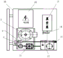
FIG. 2 is a schematic front view of a liquid compound spring push-pull vacuum liquid filling machine according to the present invention;
FIG. 3 is a schematic top view of a liquid compound spring push-pull vacuum liquid filling machine of the present invention;
description of reference numerals: the device comprises an oil tank 1, a first liquid level meter 2, an air filter 3, an oil absorption filter 4, a high-pressure water pump 5, a motor 6, a one-way valve 7, a high-pressure water pump electric contact pressure gauge 8, a high-pressure water pump electromagnetic valve 9-1, a vacuum pump electromagnetic valve 9-2, a liquid discharge electromagnetic valve 9-3, a vacuumizing quick-change connector 10, a second liquid level meter 11, a gas-liquid separator 12, an oil return filter 13, an electric contact vacuum pressure gauge 14, a vacuum pump 15, a frame 16, a roller 17 and an electric cabinet 18.
Detailed Description
Referring to fig. 1, 2 and 3, the liquid composite spring push-pull vacuum liquid injection machine comprises an oil tank 1, a first liquid level meter 2, an air filter 3, an oil absorption filter 4, a high-pressure water pump 5, a motor 6, a one-way valve 7, a high-pressure water pump electric contact pressure gauge 8, a high-pressure water pump electromagnetic valve 9-1, a vacuum pump electromagnetic valve 9-2, a liquid discharge electromagnetic valve 9-3, a vacuum pumping quick-change connector 10, a second liquid level meter 11, a gas-liquid separator 12, an oil return filter 13, an electric contact vacuum pressure gauge 14, a vacuum pump 15, a frame 16, a roller 17 and an electric cabinet 18. The vacuum pump is connected with the gas-liquid separator through a pipeline, the gas-liquid separator is connected with the vacuum pump electromagnetic valve through a pipeline, and the vacuum pump electromagnetic valve is connected with the vacuumizing quick-change connector through a pipeline; the bottom of the gas-liquid separator is connected with a liquid discharge electromagnetic valve through a pipeline, and the liquid discharge electromagnetic valve is connected with an oil tank through a pipeline; the high-pressure water pump is connected with the oil tank through a pipeline, the high-pressure water pump electromagnetic valve is connected with the high-pressure water pump through a pipeline, and the vacuumizing quick-change connector is connected with the high-pressure water pump electromagnetic valve through a pipeline. A first liquid level meter and an air filter are arranged on the oil tank; an oil absorption filter is arranged on a pipeline between the high-pressure water pump and the oil tank. A one-way valve and a high-pressure water pump electric contact pressure gauge connected with the high-pressure water pump are arranged on a pipeline between the high-pressure water pump and the high-pressure water pump electromagnetic valve; a second liquid level meter is arranged on the gas-liquid separator; an oil return filter is arranged on a pipeline between the gas-liquid separator and the oil tank; an electric contact vacuum pressure gauge is connected on a pipeline between the vacuum pump and the electromagnetic valve of the vacuum pump.
The gas-liquid separator is a closed container, a cavity partition plate is vertically arranged at the upper part in the gas-liquid separator, the upper part in the gas-liquid separator is divided into two cavities by the cavity partition plate, and the top edge and the side edge of the cavity partition plate are respectively and hermetically connected with the top surface and the side wall of the inner wall of the gas-liquid separator; the vacuum pump is connected to the top of one cavity of the gas-liquid separator through a pipeline, and the vacuum pump electromagnetic valve is connected to the top of the other cavity of the gas-liquid separator through a pipeline.
The liquid composite spring push-pull type vacuum liquid injection machine adopts the parallel connection of liquid injection and a vacuum loop; the two circuits do not produce functional entanglement. A high-pressure water pump, a vacuum pump and accessories thereof form a parallel loop.
In order to be convenient to use, the liquid composite spring push-pull type vacuum liquid injection machine is designed into a push-pull type device; the whole device (the liquid composite spring push-pull type vacuum liquid injection machine) is 800 x 700 x 1000mm in length, width and height, and the convenience of field movement is ensured. The electric control box, the oil tank, the motor, the high-pressure water pump, the vacuum pump electromagnetic valve, the high-pressure water pump electromagnetic valve, the liquid discharge electromagnetic valve, the liquid level meter I, the liquid level meter II, the high-pressure water pump electric contact pressure meter, the electric contact vacuum pressure meter, the one-way valve and other components except the frame are all installed on the frame, and the layout and the overall layout of the components on the frame ensure that the weight is uniform. Is convenient to move. The left side of the frame is provided with a push handle, and the idler wheels are arranged below the frame. The vacuum pump and the gas-liquid separator are respectively arranged at the front and the rear of the right part of the frame. The oil tank, the high-pressure water pump, the motor and the electric cabinet are arranged at the left part of the frame. The medium box (comprising an oil tank, a gas-liquid separator and the like), the high-pressure water pump, the vacuum pump, the electric cabinet and the like are connected to corresponding positions of the frame in a bolt or other modes; the pipeline, the control valve (comprising a one-way valve 7, a high-pressure water pump electromagnetic valve 9-1, a vacuum pump electromagnetic valve 9-2, a liquid discharge electromagnetic valve 9-3 and the like), the display meter (comprising a high-pressure water pump electric contact pressure gauge 8 and an electric contact vacuum pressure gauge 14), the filtering device (comprising an air filter 3, an oil absorption filter 4, an oil return filter 13 and the like) are connected by threaded joints; the two loops are connected in parallel and then the serial pipe ends are connected with the vacuumizing quick-change connector.
The liquid-gas connection loop connected with the liquid composite spring is an independent functional part consisting of a pipeline (adopting a gas pipe) and a joint. The liquid filling port of the liquid composite spring is provided with a plug for preventing the medium from flowing back. The air pipe and the connector form an independent functional part, and the air pipe and the connector are connected with a vacuumizing quick-change connector through threaded connectors connected in parallel in pairs and serially connected connectors connected in parallel.
And pipelines connected with the gas-liquid separator are hermetically connected with the gas-liquid separator. The vacuum pump, the gas-liquid separator, the motor, the high-pressure water pump, the vacuum pump electromagnetic valve, the high-pressure water pump electromagnetic valve, the liquid discharge electromagnetic valve, the liquid level meter I, the liquid level meter II, the high-pressure water pump electric contact pressure meter, the electric contact vacuum pressure meter and the one-way valve are all connected with the electric cabinet.
When the system works, the electromagnetic valves of the high-pressure water pump and the liquid discharge electromagnetic valve are closed, the electromagnetic valve of the vacuum pump is opened, and meanwhile, the vacuum pump is started to finish the vacuumizing action. When the vacuum degree reaches a set value, the vacuum pump electromagnetic valve and the vacuum pump are closed, meanwhile, the high-pressure water pump electromagnetic valve is opened, the high-pressure water pump is started, the liquid injection process is completed, if a field product test needs pressure maintaining for a set time, the high-pressure water pump is in a starting state, and the pressure maintaining inspection process is achieved.
After the pressure maintaining process is finished, if the medium needs to be recovered; and closing the high-pressure water pump electromagnetic valve and the high-pressure water pump, simultaneously opening the vacuum pump electromagnetic valve 9-2, starting the vacuum pump, and completing the process of returning liquid to the gas-liquid separator from the vacuum degree to a set value. When the liquid level of the gas-liquid separator reaches the control range of the liquid level meter, the vacuum pump stops acting, the liquid discharge electromagnetic valve 9-3 is opened to finish the liquid discharge process, and medium recovery is realized.
The design of the gas-liquid separator mainly uses a cavity separation mode to carry out backflow and separation by utilizing negative pressure and liquid gravity, the height of a cavity separation plate is in direct relation with the minimum unit flow of the negative pressure and medium backflow, the direction of the negative pressure at a backflow outlet end can be changed by the cavity separation plate, the sum of the volumes of media in a plurality of liquid composite spring cavities injected with liquid simultaneously is smaller than the space volume of the gas-liquid separator, which is less than 3 ~ 5mm away from the bottom edge of the cavity separation plate in the cavity separation plate, namely, after all the media in the plurality of liquid composite spring cavities injected with liquid simultaneously are recovered and flow into the gas-liquid separator, the vertical distance between the liquid level of the media in the gas-liquid separator and the bottom edge of the cavity separation plate is 3 ~ 5 mm.
In the invention, as long as gas-liquid separation can be realized, the cavity separation can adopt various types of variation modes, such as: and an airflow channel is reserved at the lower part of the cavity partition plate, and the airflow channel and the maximum liquid level height in the gas-liquid separator keep a required proper distance. The invention aims to perform liquid injection inspection and construction site liquid injection operation on the liquid composite spring before delivery, and form a market product.
The above description is only a preferred embodiment of the present invention and is not intended to limit the present invention, and various modifications and changes may be made by those skilled in the art. Any modification, equivalent replacement, or improvement made within the spirit and principle of the present invention shall fall within the protection scope of the present invention.
Claims (10)
1. A liquid composite spring push-pull type vacuum liquid injection machine comprises a vacuum pump, a vacuum pump electromagnetic valve and a vacuumizing quick-change connector, and is characterized by also comprising an oil tank, a gas-liquid separator, a high-pressure water pump electromagnetic valve and a liquid discharge electromagnetic valve; the vacuum pump is connected with the gas-liquid separator through a pipeline, the gas-liquid separator is connected with the vacuum pump electromagnetic valve through a pipeline, and the vacuum pump electromagnetic valve is connected with the vacuumizing quick-change connector through a pipeline; the bottom of the gas-liquid separator is connected with a liquid discharge electromagnetic valve through a pipeline, and the liquid discharge electromagnetic valve is connected with an oil tank through a pipeline; the high-pressure water pump is connected with the oil tank through a pipeline, the high-pressure water pump electromagnetic valve is connected with the high-pressure water pump through a pipeline, and the vacuumizing quick-change connector is connected with the high-pressure water pump electromagnetic valve through a pipeline.
2. A liquid composite spring push-pull type vacuum liquid filling machine as claimed in claim 1, wherein a liquid level meter I and an air filter are mounted on a fuel tank; an oil absorption filter is arranged on a pipeline between the high-pressure water pump and the oil tank.
3. A liquid composite spring push-pull type vacuum liquid injection machine according to claim 2, further comprising a motor connected with a high-pressure water pump, wherein a one-way valve and a high-pressure water pump electric contact pressure gauge are arranged on a pipeline between the high-pressure water pump and the high-pressure water pump electromagnetic valve; a second liquid level meter is arranged on the gas-liquid separator; an oil return filter is arranged on a pipeline between the liquid discharge electromagnetic valve and the oil tank; an electric contact vacuum pressure gauge is connected on a pipeline between the vacuum pump and the gas-liquid separator.
4. A liquid compound spring push-pull vacuum liquid filling machine as claimed in claim 3, further comprising an electric cabinet; the vacuum pump, the gas-liquid separator, the motor, the high-pressure water pump, the vacuum pump electromagnetic valve, the high-pressure water pump electromagnetic valve, the liquid discharge electromagnetic valve, the liquid level meter I, the liquid level meter II, the high-pressure water pump electric contact pressure meter, the electric contact vacuum pressure meter, the one-way valve and the oil tank are all connected with the electric cabinet.
5. A composite spring push-pull type vacuum liquid filling machine as claimed in claim 4, further comprising a frame and rollers mounted under the frame; the electric cabinet, the vacuum pump, the oil tank, the gas-liquid separator and the high-pressure water pump are all installed on the frame.
6. The liquid composite spring push-pull type vacuum liquid injection machine as claimed in claim 1, wherein the gas-liquid separator is a closed container, a cavity separation plate is vertically arranged at the upper part in the gas-liquid separator, the cavity separation plate separates the upper part in the gas-liquid separator into two cavities, and the top edge and the side edge of the cavity separation plate are respectively connected with the top surface and the side wall of the inner wall of the gas-liquid separator in a sealing manner; the vacuum pump is connected with one cavity of the gas-liquid separator through a pipeline, and the electromagnetic valve of the vacuum pump is connected with the other cavity of the gas-liquid separator through a pipeline.
7. A push-pull vacuum liquid filling machine with a composite spring for liquid according to claim 6, wherein the height of the bottom edge of the cavity partition plate is matched with the negative pressure and the minimum unit flow rate of medium backflow, and the volume of the space in the gas-liquid separator, which is less than 3 ~ 5mm from the bottom edge of the cavity partition plate, is greater than the total volume of the media in the cavities of the multiple composite spring for liquid filling at the same time.
8. A liquid injection method for a liquid composite spring comprises the steps of vacuumizing, injecting liquid and recovering a medium, and is characterized in that the step of recovering the medium adopts a gas-liquid separation mode, a gas-liquid separator is arranged in a vacuumizing device, the upper part in the gas-liquid separator is divided into two cavities, the two cavities are respectively connected with a vacuum pump and the liquid composite spring, and during medium recovery, the cavities are separated to carry out backflow and separation by utilizing negative pressure and liquid gravity, so that gas-liquid separation is realized.
9. The method of injecting liquid into a composite liquid spring as claimed in claim 8, wherein a cavity divider is used to divide the upper part of the gas-liquid separator into two cavities, and the maximum liquid level in the gas-liquid separator is 3 ~ 5mm lower than the bottom edge of the cavity divider, the height of the cavity divider is set according to the minimum unit flow of negative pressure and medium reflux, the direction of the negative pressure at the reflux outlet end is changed by the cavity divider, and the volume of the liquid at the maximum liquid level in the gas-liquid separator is greater than the sum of the volumes of the media in the cavities of the composite liquid springs for simultaneous injection.
10. The method for injecting the liquid composite spring as claimed in claim 8, wherein the liquid composite spring push-pull type vacuum injection machine as claimed in claim 1 is used for injecting the liquid;
when the vacuum pump works, the electromagnetic valve of the high-pressure water pump and the electromagnetic valve of the liquid discharge are closed, the electromagnetic valve of the vacuum pump is opened, the vacuum pump is started, and the vacuum pump is vacuumized; when the vacuum degree reaches a set value, closing the vacuum pump electromagnetic valve and the vacuum pump, simultaneously opening the high-pressure water pump electromagnetic valve, starting the high-pressure water pump, and injecting liquid into the liquid composite spring; after the liquid injection is finished, if the field product test is carried out, the pressure is maintained for a set time, the high-pressure water pump is in a starting state, and the pressure maintaining inspection is carried out;
after the pressure maintaining process is finished, when a medium is recovered, the high-pressure water pump electromagnetic valve and the high-pressure water pump are closed, the vacuum pump electromagnetic valve is opened, the vacuum degree is set, the vacuum pump is started, when the liquid level in the gas-liquid separator reaches the control range of the liquid level meter, the vacuum pump stops acting, the liquid drainage electromagnetic valve is opened, the liquid drainage process is finished, and the medium recovery is realized.
Priority Applications (1)
| Application Number | Priority Date | Filing Date | Title |
|---|---|---|---|
| CN201810783260.9A CN110723710B (en) | 2018-07-17 | 2018-07-17 | Liquid composite spring push-pull type vacuum liquid injection machine and liquid injection method |
Applications Claiming Priority (1)
| Application Number | Priority Date | Filing Date | Title |
|---|---|---|---|
| CN201810783260.9A CN110723710B (en) | 2018-07-17 | 2018-07-17 | Liquid composite spring push-pull type vacuum liquid injection machine and liquid injection method |
Publications (2)
| Publication Number | Publication Date |
|---|---|
| CN110723710A true CN110723710A (en) | 2020-01-24 |
| CN110723710B CN110723710B (en) | 2021-05-14 |
Family
ID=69217014
Family Applications (1)
| Application Number | Title | Priority Date | Filing Date |
|---|---|---|---|
| CN201810783260.9A Active CN110723710B (en) | 2018-07-17 | 2018-07-17 | Liquid composite spring push-pull type vacuum liquid injection machine and liquid injection method |
Country Status (1)
| Country | Link |
|---|---|
| CN (1) | CN110723710B (en) |
Cited By (2)
| Publication number | Priority date | Publication date | Assignee | Title |
|---|---|---|---|---|
| CN110376358A (en) * | 2019-06-24 | 2019-10-25 | 湖北三江航天红峰控制有限公司 | The granularity sync detection device and detection method of vacuum filling |
| CN111777029A (en) * | 2020-06-17 | 2020-10-16 | 新乡航空工业(集团)有限公司 | Automatic vacuum pumping and liquid injecting device of pod environment control system |
Citations (14)
| Publication number | Priority date | Publication date | Assignee | Title |
|---|---|---|---|---|
| CN101769655A (en) * | 2010-01-25 | 2010-07-07 | 大连三洋压缩机有限公司 | Automatic recovery and fill system of refrigeration system |
| CN202207515U (en) * | 2011-08-26 | 2012-05-02 | 湖南果秀食品有限公司 | Gas-liquid separation device used for vacuum packaging equipment |
| CN202300961U (en) * | 2011-09-30 | 2012-07-04 | 自贡市华瑞过滤设备制造有限公司 | Frequency conversion vacuum oil-injecting machine |
| CN102979700A (en) * | 2012-11-30 | 2013-03-20 | 东莞台一盈拓科技股份有限公司 | Automatic draining device for vacuum pump and vacuum pump |
| CN203048582U (en) * | 2013-01-17 | 2013-07-10 | 济南易恒技术有限公司 | Silicone oil filling machine |
| CN103674587A (en) * | 2012-09-13 | 2014-03-26 | 南车青岛四方机车车辆股份有限公司 | Test system and method for detection of air conditioning system |
| KR20140103423A (en) * | 2013-02-18 | 2014-08-27 | 원영식 | Potable vacuum inhaling apparatus |
| CN203998896U (en) * | 2014-07-10 | 2014-12-10 | 国家电网公司 | Hydraulic spring mechanism vacuum oiling device |
| CN104961090A (en) * | 2015-06-25 | 2015-10-07 | 国网山东省电力公司济南供电公司 | Simple oil injecting device of hydraulic mechanism |
| CN105650190A (en) * | 2016-03-04 | 2016-06-08 | 国机集团北京飞行强度研究所有限公司 | Undercarriage buffer support column inner cavity oil filling device |
| CN205618150U (en) * | 2016-05-20 | 2016-10-05 | 孔磊 | Novel many wells measurement separation device |
| CN106241714A (en) * | 2016-09-19 | 2016-12-21 | 中国海洋石油总公司 | A kind of portable injection system |
| JP2017129363A (en) * | 2016-01-18 | 2017-07-27 | アズビル株式会社 | Oil injection device and oil injection method |
| CN107795454A (en) * | 2017-09-12 | 2018-03-13 | 广州嘉诺工业技术有限公司 | A kind of wind-driven generator liquid spring vacuumizes pressurizer |
-
2018
- 2018-07-17 CN CN201810783260.9A patent/CN110723710B/en active Active
Patent Citations (14)
| Publication number | Priority date | Publication date | Assignee | Title |
|---|---|---|---|---|
| CN101769655A (en) * | 2010-01-25 | 2010-07-07 | 大连三洋压缩机有限公司 | Automatic recovery and fill system of refrigeration system |
| CN202207515U (en) * | 2011-08-26 | 2012-05-02 | 湖南果秀食品有限公司 | Gas-liquid separation device used for vacuum packaging equipment |
| CN202300961U (en) * | 2011-09-30 | 2012-07-04 | 自贡市华瑞过滤设备制造有限公司 | Frequency conversion vacuum oil-injecting machine |
| CN103674587A (en) * | 2012-09-13 | 2014-03-26 | 南车青岛四方机车车辆股份有限公司 | Test system and method for detection of air conditioning system |
| CN102979700A (en) * | 2012-11-30 | 2013-03-20 | 东莞台一盈拓科技股份有限公司 | Automatic draining device for vacuum pump and vacuum pump |
| CN203048582U (en) * | 2013-01-17 | 2013-07-10 | 济南易恒技术有限公司 | Silicone oil filling machine |
| KR20140103423A (en) * | 2013-02-18 | 2014-08-27 | 원영식 | Potable vacuum inhaling apparatus |
| CN203998896U (en) * | 2014-07-10 | 2014-12-10 | 国家电网公司 | Hydraulic spring mechanism vacuum oiling device |
| CN104961090A (en) * | 2015-06-25 | 2015-10-07 | 国网山东省电力公司济南供电公司 | Simple oil injecting device of hydraulic mechanism |
| JP2017129363A (en) * | 2016-01-18 | 2017-07-27 | アズビル株式会社 | Oil injection device and oil injection method |
| CN105650190A (en) * | 2016-03-04 | 2016-06-08 | 国机集团北京飞行强度研究所有限公司 | Undercarriage buffer support column inner cavity oil filling device |
| CN205618150U (en) * | 2016-05-20 | 2016-10-05 | 孔磊 | Novel many wells measurement separation device |
| CN106241714A (en) * | 2016-09-19 | 2016-12-21 | 中国海洋石油总公司 | A kind of portable injection system |
| CN107795454A (en) * | 2017-09-12 | 2018-03-13 | 广州嘉诺工业技术有限公司 | A kind of wind-driven generator liquid spring vacuumizes pressurizer |
Cited By (2)
| Publication number | Priority date | Publication date | Assignee | Title |
|---|---|---|---|---|
| CN110376358A (en) * | 2019-06-24 | 2019-10-25 | 湖北三江航天红峰控制有限公司 | The granularity sync detection device and detection method of vacuum filling |
| CN111777029A (en) * | 2020-06-17 | 2020-10-16 | 新乡航空工业(集团)有限公司 | Automatic vacuum pumping and liquid injecting device of pod environment control system |
Also Published As
| Publication number | Publication date |
|---|---|
| CN110723710B (en) | 2021-05-14 |
Similar Documents
| Publication | Publication Date | Title |
|---|---|---|
| CN110723710B (en) | Liquid composite spring push-pull type vacuum liquid injection machine and liquid injection method | |
| CN103066238B (en) | High-efficiency acid discharge system of storage battery | |
| CN103490036B (en) | Positive-suction type lithium ion battery liquid injection box | |
| CN106159188A (en) | A kind of through electrolyte filling method of lithium ion battery and device | |
| CN208442574U (en) | A kind of liquefied natural gas leakage collection device | |
| CN212795638U (en) | Cooling device of foam molding machine | |
| CN203039017U (en) | Accumulator efficient acid discharge system | |
| CN216698678U (en) | Lithium battery liquid injection machine convenient for feeding and discharging | |
| CN206860568U (en) | LNG/L CNG hydraulic pressure intensifiers and gas station | |
| CN110098372A (en) | A kind of lithium-ion battery liquid injection device | |
| CN206682608U (en) | Underground power house turbine oil depot oil filtering system pipeline structure | |
| CN201616469U (en) | Pregnant solution kettle for solution charging of storage battery | |
| CN210912986U (en) | Lubricating oil liquid filling machine for filling | |
| CN209561532U (en) | A kind of filling machine equipressure priming device | |
| CN211902385U (en) | Liquid filling equipment | |
| CN204011090U (en) | A kind of ultracapacitor vacuum electrolyte filling device | |
| CN219287939U (en) | Energy cabinet | |
| CN211501172U (en) | Hydraulic system of roller press | |
| CN217976492U (en) | Ion compressor rear end buffer with ionic liquid recovery function | |
| CN217134424U (en) | Reversible hydrogen fuel cell system coolant filling device | |
| CN103497136A (en) | High-vacuum continuous-draining device | |
| CN209908558U (en) | Gel pressure injection equipment for goaf surface | |
| CN213450348U (en) | Chemical adding device for water injection well | |
| CN213513954U (en) | Catalytic combustion equipment with exhaust cooling function | |
| CN215489103U (en) | Series-parallel gas-liquid mixed transportation supercharging device |
Legal Events
| Date | Code | Title | Description |
|---|---|---|---|
| PB01 | Publication | ||
| PB01 | Publication | ||
| SE01 | Entry into force of request for substantive examination | ||
| SE01 | Entry into force of request for substantive examination | ||
| GR01 | Patent grant | ||
| GR01 | Patent grant |