CN110711306B - Ureter bracket - Google Patents
Ureter bracket Download PDFInfo
- Publication number
- CN110711306B CN110711306B CN201911081095.3A CN201911081095A CN110711306B CN 110711306 B CN110711306 B CN 110711306B CN 201911081095 A CN201911081095 A CN 201911081095A CN 110711306 B CN110711306 B CN 110711306B
- Authority
- CN
- China
- Prior art keywords
- stent
- section
- ureteral
- proximal
- proximal section
- Prior art date
- Legal status (The legal status is an assumption and is not a legal conclusion. Google has not performed a legal analysis and makes no representation as to the accuracy of the status listed.)
- Expired - Fee Related
Links
- 210000000626 ureter Anatomy 0.000 title claims abstract description 48
- 210000003734 kidney Anatomy 0.000 claims abstract description 33
- 239000000463 material Substances 0.000 claims description 55
- 230000007423 decrease Effects 0.000 claims description 9
- 210000002700 urine Anatomy 0.000 description 15
- 210000002105 tongue Anatomy 0.000 description 10
- 239000004575 stone Substances 0.000 description 8
- 238000004519 manufacturing process Methods 0.000 description 5
- 206010028980 Neoplasm Diseases 0.000 description 4
- 239000004952 Polyamide Substances 0.000 description 4
- 229920002614 Polyether block amide Polymers 0.000 description 4
- 208000026723 Urinary tract disease Diseases 0.000 description 4
- -1 e.g. Polymers 0.000 description 4
- 238000000034 method Methods 0.000 description 4
- 229920002647 polyamide Polymers 0.000 description 4
- 208000014001 urinary system disease Diseases 0.000 description 4
- 229920001577 copolymer Polymers 0.000 description 3
- 230000029142 excretion Effects 0.000 description 3
- 229920000642 polymer Polymers 0.000 description 3
- 229920002635 polyurethane Polymers 0.000 description 3
- 239000004814 polyurethane Substances 0.000 description 3
- 239000000126 substance Substances 0.000 description 3
- 229920002725 thermoplastic elastomer Polymers 0.000 description 3
- 239000004433 Thermoplastic polyurethane Substances 0.000 description 2
- 229920003235 aromatic polyamide Polymers 0.000 description 2
- 125000003118 aryl group Chemical group 0.000 description 2
- JHIVVAPYMSGYDF-UHFFFAOYSA-N cyclohexanone Chemical compound O=C1CCCCC1 JHIVVAPYMSGYDF-UHFFFAOYSA-N 0.000 description 2
- 201000010099 disease Diseases 0.000 description 2
- 208000037265 diseases, disorders, signs and symptoms Diseases 0.000 description 2
- 230000000694 effects Effects 0.000 description 2
- 230000007794 irritation Effects 0.000 description 2
- 230000014759 maintenance of location Effects 0.000 description 2
- 230000027939 micturition Effects 0.000 description 2
- 239000000203 mixture Substances 0.000 description 2
- 230000002572 peristaltic effect Effects 0.000 description 2
- 229920001296 polysiloxane Polymers 0.000 description 2
- 238000005096 rolling process Methods 0.000 description 2
- 229920002803 thermoplastic polyurethane Polymers 0.000 description 2
- 208000002193 Pain Diseases 0.000 description 1
- 239000004698 Polyethylene Substances 0.000 description 1
- 239000002202 Polyethylene glycol Substances 0.000 description 1
- 229920000954 Polyglycolide Polymers 0.000 description 1
- 239000004743 Polypropylene Substances 0.000 description 1
- 206010038419 Renal colic Diseases 0.000 description 1
- 229910000831 Steel Inorganic materials 0.000 description 1
- 208000012931 Urologic disease Diseases 0.000 description 1
- 229920003232 aliphatic polyester Polymers 0.000 description 1
- 239000004760 aramid Substances 0.000 description 1
- 150000001875 compounds Chemical class 0.000 description 1
- 238000001816 cooling Methods 0.000 description 1
- 230000002950 deficient Effects 0.000 description 1
- 238000007598 dipping method Methods 0.000 description 1
- 230000005489 elastic deformation Effects 0.000 description 1
- 239000005038 ethylene vinyl acetate Substances 0.000 description 1
- 238000001125 extrusion Methods 0.000 description 1
- 238000010438 heat treatment Methods 0.000 description 1
- 239000004761 kevlar Substances 0.000 description 1
- 239000004763 nomex Substances 0.000 description 1
- 230000035479 physiological effects, processes and functions Effects 0.000 description 1
- 239000004014 plasticizer Substances 0.000 description 1
- 229920000728 polyester Polymers 0.000 description 1
- 229920000570 polyether Polymers 0.000 description 1
- 229920000573 polyethylene Polymers 0.000 description 1
- 229920001223 polyethylene glycol Polymers 0.000 description 1
- 239000004633 polyglycolic acid Substances 0.000 description 1
- 229920001155 polypropylene Polymers 0.000 description 1
- 229920002742 polystyrene-block-poly(ethylene/propylene) -block-polystyrene Polymers 0.000 description 1
- 229920002743 polystyrene-poly(ethylene-ethylene/propylene) block-polystyrene Polymers 0.000 description 1
- 229920000346 polystyrene-polyisoprene block-polystyrene Polymers 0.000 description 1
- 239000004800 polyvinyl chloride Substances 0.000 description 1
- 229920000915 polyvinyl chloride Polymers 0.000 description 1
- 230000029058 respiratory gaseous exchange Effects 0.000 description 1
- 239000010959 steel Substances 0.000 description 1
- 229920000468 styrene butadiene styrene block copolymer Polymers 0.000 description 1
- 229920001935 styrene-ethylene-butadiene-styrene Polymers 0.000 description 1
- 210000003708 urethra Anatomy 0.000 description 1
- 238000003466 welding Methods 0.000 description 1
Images


Classifications
-
- A—HUMAN NECESSITIES
- A61—MEDICAL OR VETERINARY SCIENCE; HYGIENE
- A61F—FILTERS IMPLANTABLE INTO BLOOD VESSELS; PROSTHESES; DEVICES PROVIDING PATENCY TO, OR PREVENTING COLLAPSING OF, TUBULAR STRUCTURES OF THE BODY, e.g. STENTS; ORTHOPAEDIC, NURSING OR CONTRACEPTIVE DEVICES; FOMENTATION; TREATMENT OR PROTECTION OF EYES OR EARS; BANDAGES, DRESSINGS OR ABSORBENT PADS; FIRST-AID KITS
- A61F2/00—Filters implantable into blood vessels; Prostheses, i.e. artificial substitutes or replacements for parts of the body; Appliances for connecting them with the body; Devices providing patency to, or preventing collapsing of, tubular structures of the body, e.g. stents
- A61F2/02—Prostheses implantable into the body
- A61F2/04—Hollow or tubular parts of organs, e.g. bladders, tracheae, bronchi or bile ducts
-
- A—HUMAN NECESSITIES
- A61—MEDICAL OR VETERINARY SCIENCE; HYGIENE
- A61M—DEVICES FOR INTRODUCING MEDIA INTO, OR ONTO, THE BODY; DEVICES FOR TRANSDUCING BODY MEDIA OR FOR TAKING MEDIA FROM THE BODY; DEVICES FOR PRODUCING OR ENDING SLEEP OR STUPOR
- A61M27/00—Drainage appliance for wounds or the like, i.e. wound drains, implanted drains
- A61M27/002—Implant devices for drainage of body fluids from one part of the body to another
- A61M27/008—Implant devices for drainage of body fluids from one part of the body to another pre-shaped, for use in the urethral or ureteral tract
-
- A—HUMAN NECESSITIES
- A61—MEDICAL OR VETERINARY SCIENCE; HYGIENE
- A61F—FILTERS IMPLANTABLE INTO BLOOD VESSELS; PROSTHESES; DEVICES PROVIDING PATENCY TO, OR PREVENTING COLLAPSING OF, TUBULAR STRUCTURES OF THE BODY, e.g. STENTS; ORTHOPAEDIC, NURSING OR CONTRACEPTIVE DEVICES; FOMENTATION; TREATMENT OR PROTECTION OF EYES OR EARS; BANDAGES, DRESSINGS OR ABSORBENT PADS; FIRST-AID KITS
- A61F2/00—Filters implantable into blood vessels; Prostheses, i.e. artificial substitutes or replacements for parts of the body; Appliances for connecting them with the body; Devices providing patency to, or preventing collapsing of, tubular structures of the body, e.g. stents
- A61F2/82—Devices providing patency to, or preventing collapsing of, tubular structures of the body, e.g. stents
- A61F2/94—Stents retaining their form, i.e. not being deformable, after placement in the predetermined place
-
- A—HUMAN NECESSITIES
- A61—MEDICAL OR VETERINARY SCIENCE; HYGIENE
- A61F—FILTERS IMPLANTABLE INTO BLOOD VESSELS; PROSTHESES; DEVICES PROVIDING PATENCY TO, OR PREVENTING COLLAPSING OF, TUBULAR STRUCTURES OF THE BODY, e.g. STENTS; ORTHOPAEDIC, NURSING OR CONTRACEPTIVE DEVICES; FOMENTATION; TREATMENT OR PROTECTION OF EYES OR EARS; BANDAGES, DRESSINGS OR ABSORBENT PADS; FIRST-AID KITS
- A61F2/00—Filters implantable into blood vessels; Prostheses, i.e. artificial substitutes or replacements for parts of the body; Appliances for connecting them with the body; Devices providing patency to, or preventing collapsing of, tubular structures of the body, e.g. stents
- A61F2/02—Prostheses implantable into the body
- A61F2/04—Hollow or tubular parts of organs, e.g. bladders, tracheae, bronchi or bile ducts
- A61F2002/048—Ureters
-
- A—HUMAN NECESSITIES
- A61—MEDICAL OR VETERINARY SCIENCE; HYGIENE
- A61F—FILTERS IMPLANTABLE INTO BLOOD VESSELS; PROSTHESES; DEVICES PROVIDING PATENCY TO, OR PREVENTING COLLAPSING OF, TUBULAR STRUCTURES OF THE BODY, e.g. STENTS; ORTHOPAEDIC, NURSING OR CONTRACEPTIVE DEVICES; FOMENTATION; TREATMENT OR PROTECTION OF EYES OR EARS; BANDAGES, DRESSINGS OR ABSORBENT PADS; FIRST-AID KITS
- A61F2250/00—Special features of prostheses classified in groups A61F2/00 - A61F2/26 or A61F2/82 or A61F9/00 or A61F11/00 or subgroups thereof
- A61F2250/0014—Special features of prostheses classified in groups A61F2/00 - A61F2/26 or A61F2/82 or A61F9/00 or A61F11/00 or subgroups thereof having different values of a given property or geometrical feature, e.g. mechanical property or material property, at different locations within the same prosthesis
- A61F2250/0018—Special features of prostheses classified in groups A61F2/00 - A61F2/26 or A61F2/82 or A61F9/00 or A61F11/00 or subgroups thereof having different values of a given property or geometrical feature, e.g. mechanical property or material property, at different locations within the same prosthesis differing in elasticity, stiffness or compressibility
-
- A—HUMAN NECESSITIES
- A61—MEDICAL OR VETERINARY SCIENCE; HYGIENE
- A61F—FILTERS IMPLANTABLE INTO BLOOD VESSELS; PROSTHESES; DEVICES PROVIDING PATENCY TO, OR PREVENTING COLLAPSING OF, TUBULAR STRUCTURES OF THE BODY, e.g. STENTS; ORTHOPAEDIC, NURSING OR CONTRACEPTIVE DEVICES; FOMENTATION; TREATMENT OR PROTECTION OF EYES OR EARS; BANDAGES, DRESSINGS OR ABSORBENT PADS; FIRST-AID KITS
- A61F2250/00—Special features of prostheses classified in groups A61F2/00 - A61F2/26 or A61F2/82 or A61F9/00 or A61F11/00 or subgroups thereof
- A61F2250/0014—Special features of prostheses classified in groups A61F2/00 - A61F2/26 or A61F2/82 or A61F9/00 or A61F11/00 or subgroups thereof having different values of a given property or geometrical feature, e.g. mechanical property or material property, at different locations within the same prosthesis
- A61F2250/0036—Special features of prostheses classified in groups A61F2/00 - A61F2/26 or A61F2/82 or A61F9/00 or A61F11/00 or subgroups thereof having different values of a given property or geometrical feature, e.g. mechanical property or material property, at different locations within the same prosthesis differing in thickness
-
- A—HUMAN NECESSITIES
- A61—MEDICAL OR VETERINARY SCIENCE; HYGIENE
- A61M—DEVICES FOR INTRODUCING MEDIA INTO, OR ONTO, THE BODY; DEVICES FOR TRANSDUCING BODY MEDIA OR FOR TAKING MEDIA FROM THE BODY; DEVICES FOR PRODUCING OR ENDING SLEEP OR STUPOR
- A61M2210/00—Anatomical parts of the body
- A61M2210/10—Trunk
- A61M2210/1078—Urinary tract
- A61M2210/1082—Kidney
Abstract
The invention discloses a ureteral stent, which comprises: a body having a kidney section configured for placement in a kidney of a patient, a ureter section, and a proximal section, the ureter section being connected to the kidney section and configured for placement in a ureter of a patient, the proximal section being connected to the ureter section at a proximal end of the body, and the proximal section being disposed at the proximal end of the body; and a tail comprising a wire, the wire being connected to the proximal end of the body of the stent; wherein the proximal section is tubular and is provided with a first flexibility which is greater than a second flexibility of the ureteral section of the stent, the tubular proximal section comprising a plurality of through openings.
Description
The application is a divisional application of patent applications with the international application date of 2015, 04 and 10, international application numbers of PCT/DK2015/050087, national stage entry date of 2016, 10 and 10, national application number of 201580018865.3 and the name of ureteral stent.
Technical Field
The present invention relates to a ureteral stent intended to maintain the flow of urine between the kidney and the bladder of a patient.
Background
In the human body, urine secreted by the kidneys passes through the ureters to the bladder and is then excreted from the body through the urethra during urination. In a healthy human body, urine is excreted from the kidney to the bladder in one direction by means of peristaltic movement of the ureters.
Certain urinary tract disorders or certain diseases may hamper such excretion in the direction of the bladder. These conditions may be caused in particular by the presence of stones or tumors or obstructions at the pyeloureteral junction. In this case, the flow of urine to the bladder may be difficult or may no longer be possible at all. Urine remaining in the kidneys swells and can cause renal colic. To alleviate this condition, a stent may be placed in the ureter to restore the function of the ureter and allow for urination.
Patients and surgeons would welcome improvements relating to stents.
Disclosure of Invention
According to one aspect of the present invention, there is provided a ureteral stent comprising: a body having a kidney section configured for placement in a kidney of a patient, a ureter section, and a proximal section, the ureter section being connected to the kidney section and configured for placement in a ureter of a patient, the proximal section being connected to the ureter section at a proximal end of the body, and the proximal section being disposed at the proximal end of the body; and a tail comprising a wire, the wire being connected to the proximal end of the body of the stent; wherein the proximal section is tubular and is provided with a first flexibility which is greater than a second flexibility of the ureteral section of the stent, the tubular proximal section comprising a plurality of through openings.
According to another aspect of the invention, wherein the proximal section of the stent comprises a material that is more flexible than the material forming the ureteral section of the stent.
According to another aspect of the invention, wherein the proximal section of the stent is made of two materials of different flexibility and the proximal section has a longitudinal channel of constant diameter defined by a sidewall of constant thickness.
According to another aspect of the invention, wherein a first material of the two materials is less flexible than a second material of the two materials, and a thickness of the first material decreases towards the tail of the stent and a thickness of the second material increases towards the tail of the stent.
According to another aspect of the invention, wherein the through openings are slits.
According to another aspect of the invention, wherein the slits extend in the longitudinal direction of the proximal section.
According to another aspect of the invention, wherein the slits extend in a transverse direction of the proximal section.
According to another aspect of the invention, wherein the through openings are holes.
According to another aspect of the invention, wherein the proximal section has a conical inner recess such that a thickness of a sidewall of the proximal section decreases towards the tail of the stent.
According to another aspect of the invention, wherein the proximal section comprises a plurality of longitudinal recesses formed in the thickness of the sidewall.
According to another aspect of the invention, wherein the proximal section has a slit ring-shaped cross-section.
According to another aspect of the invention, wherein the tail is rigidly connected to the proximal section.
According to another aspect of the invention, wherein the tail is rigidly connected to the ureteral section.
According to another aspect of the invention, wherein the body portion of the stent on the proximal section has a thickness equal to or lower than 200N mm2The coefficient of flexibility of (a).
Drawings
The invention, together with its advantages, may be best understood by reference to the detailed description taken in conjunction with the accompanying drawings of which:
figure 1 is a schematic view of a stent according to one embodiment when fitted in place in a patient's body;
figure 2 is a full view of a ureteral stent according to an embodiment;
FIG. 3 is a cross-sectional view of a part of a stand according to an embodiment;
FIG. 4 is a cross-sectional view of a stent according to an embodiment;
FIG. 5 is an enlarged view of a detail of the proximal section of the embodiment of FIG. 4;
FIG. 6 is a top view of an embodiment of the stand;
figure 7 is a cross-sectional view of a portion of the embodiment of figure 6;
figure 8 shows a bracket according to an embodiment;
FIG. 9 is a cross-sectional view of a portion of the proximal section of the embodiment of FIG. 8;
figure 10 is a perspective view of this part of the embodiment of figure 9;
FIG. 11 is a perspective view of a stand according to an embodiment;
figure 12 shows a front view of the embodiment of figure 11;
figure 13 is a perspective view of a detail of the proximal section of the embodiment of figure 11;
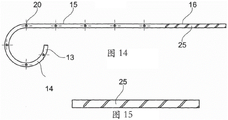
FIG. 14 is a cross-sectional view of a stent according to an embodiment;
FIG. 15 is an enlarged view of a portion of the proximal section of the embodiment of FIG. 14;
FIG. 16 is an enlarged view of one embodiment of the proximal section of the stent;
FIG. 17A is a side view of one embodiment of the proximal section of the stent;
figure 17B is a cross-sectional view of the embodiment of figure 17A;
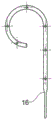
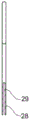
FIG. 18A is a side view of one embodiment of the proximal section of the stent;
figure 18B is a cross-sectional view of the embodiment of figure 18A;
FIG. 19A is a schematic side view of an embodiment of the proximal section of the stent;
figure 19B is a schematic side view of the embodiment of figure 19A rotated 90 degrees; and is
Fig. 19C is an end view of the proximal section of the stent according to fig. 19A and 19B.
Detailed Description
The ureteral stent of the present application comprises a body having a kidney section for placement in a kidney of a patient, a ureter section for placement in at least a portion of the patient's ureter, and a proximal section arranged at a proximal end of the stent body, and a tail having at least one wire configured to terminate in the bladder of said patient.
These embodiments relate to a stent that protects the peristaltic movement of the ureters, thereby preventing the backflow of urine in the direction of the kidneys. The stent avoids irritation of the bladder and irritation caused by friction in the ureter. The stent is therefore better received by the patient.
The ureteral stent comprises a cylindrical tubular proximal section and a circular cross-section and has a flexibility greater than the flexibility of the ureteral section of the stent.
The ureteral stent is for placement in the ureter of a patient suffering from a urinary tract disorder or disease, such as stones, tumors, or especially obstructions at the pyeloureteral junction. The stent extends up to the kidney and has a curved kidney section, the curved shape allowing the stent to be more effectively held in place in the kidney. The stent has a ureteral section that is inserted into the patient's ureter. The ureteral section extends beyond the location of the urinary tract disorder and ensures a flow path in the defective portion of the ureter. One end of the stent is provided with a tail comprising at least one wire configured to terminate in or near the bladder. The thread is adapted to allow the excretion of urine and has a sufficiently small diameter so as to be barely felt by the patient on the body.
In the following disclosure, features of the various exemplary embodiments are applicable in combination with each other, unless specifically noted otherwise.
In the following disclosure, the end refers to the most extreme position and the end portion refers to the section adjacent or near the end of the object.
FIG. 1 is a schematic view of one embodiment of a ureteral stent 10 placed in a patient with a stone C present. Fig. 2 shows a similar stent before fitting in place in the patient.
With particular reference to fig. 1 and 2, a ureteral stent 10 has a body 11 and a tail 12. The body 11 has a kidney section 13 for placement in a kidney of a patient. The kidney segment 13 has curved end portions 14 and improves retention of the stent. This part of the stent is physically imperceptible or barely perceptible to the patient and therefore does not cause any discomfort or pain.
In one embodiment, the stent includes a ureteral section 15 for placement in the patient's ureter U. Various embodiments include stents that are fabricated to have at least ureteral sections of different lengths, thereby accommodating variations in patient physiology. As indicated above, this type of ureteral stent is suitable for placement in a patient in the event of a disease or obstruction in the region of the ureter. The obstruction may be caused by the presence of a stone C (as illustrated by fig. 1), a tumor, or, in particular, a constriction. The length of the ureteral section 15 of the stent should be sufficient to ensure that, after placement of the stent, the body 11 of the stent extends beyond the site of the stone C or tumor in the direction of the bladder V.
In one embodiment, the body 11 of the stent additionally has a proximal section 16 which is integrated with the ureteral section 15 at the end distal to the renal section 13. The proximal section 16 is located in the continuation of the ureteral section 15.
In one embodiment, the tail 12 of the stent 10 is formed by at least one thread 17 or suture configured to extend from the proximal section 16 in the direction of the bladder V when the stent is placed in the patient.
In various embodiments, the cord allows urine to flow from the kidney R to the bladder V, but does not allow flow from the bladder to the kidney in the opposite direction. This avoids the above-mentioned problems, especially the feeling of having to urinate. The wire 17 causes the ureter to expand and thus allows a simpler and therefore less painful expulsion of the stones.
In one embodiment, tail 12 comprises a single wire, as illustrated in fig. 1. In one embodiment, the tail comprises two or more wires. The tail 12 is configured to terminate in and extend a few centimeters into the bladder when the stent is placed in the patient. In one embodiment, the tail extends 5 cm to 6 cm into the bladder.
In embodiments where the tail is formed from two or more wires, the wires are free and independent of each other. In other embodiments, the wires are secured to each other, for example by a knot. The knot is suitably located in the vicinity of the proximal section 16, in which case it will be positioned in the ureter during use of the stent. Alternatively, the knot is located near the end of the wires extending away from the proximal section, in which case the knot will be positioned in the bladder during use of the stent. Other means of connecting the wires to each other are also acceptable, such as, but not limited to, a braid.
In one embodiment, the ureteral section 15 and the proximal section 16 are tubular and cylindrical, that is, they have a substantially annular cross-section, with a longitudinal channel 18 defined by a side wall 19. In one embodiment, the side wall has, at least in some areas, through openings 20 which allow urine to flow from outside the holder into the longitudinal channel and vice versa. In one embodiment, the longitudinal channel 18 opens at the end of the proximal section 16 near the tail 12. In one embodiment, the kidney segment 13 also has a channel and a plurality of openings through the side wall 19. The channel 18 is used for introducing guides during placement of the stent and for excretion of urine during use of the stent.
In one embodiment, and referring to fig. 1 and 3, the proximal section 16 of the stent is flexible. In particular, this proximal section is more flexible than the ureteral section 15.
In this application, flexibility is defined as the resistance of an object to elastic deformation. The more flexible the object, the less force must be applied to it to achieve a given flexion. In this specification, rigidity or stiffness is considered to be the opposite concept of flexibility.
Flexibility can be measured by: the sample whose flexibility is being determined is placed on two punctiform supports separated by a distance L. A downward force P is applied at the center of the sample. Measuring the deformation U of a sample by measuring the movement of the centre of the sample under the action of a force Py. Allowing the deformation to be used to establish a curve as a function of forceA wire. The compliance coefficient is defined as the slope of the tangent to this curve at the origin.
From a mathematical point of view, the compliance coefficient is defined by the following formula

In one embodiment, the proximal section of the stent has a compliance coefficient less than or equal to 200 nmm2。
The more flexible the stent, the more flexible and the lower the flexibility factor.
The flexibility of the proximal section is suitably obtained by using a flexible material and/or by providing the proximal section with a shape that gives it flexibility.
In one embodiment, the proximal section of the stent is configured for allowing the body 11 of the stent to match the shape of the ureter U, in particular in a non-linear portion of the ureter, during movement of the patient, in particular movement caused by breathing. The stent and ureter are configured to allow relative offset therebetween. For this purpose, the proximal section 16 of the stent is sufficiently flexible to be able to follow the ureter.
In one embodiment, the ureteral section 15 of the stent has a flexibility that allows it to adapt to the tortuosity of the ureter. Suitable materials for the production of stents include polymers, e.g., polyurethanes, copolymers (e.g., polyether block amides known as PEBA), polyamides, silicones, polymers such as polyethylene glycol, and the likeTM、VISTAMAXXTM、QUEOTMOr NOTIOTMPolyolefins sold under the name polyamide, polyvinyl chloride (PVC), thermoplastic polyurethanes, aromatic polyethers, aromatic and aliphatic polyesters with a Shore hardness generally between 25 and 95, compounds based on thermoplastic elastomers, vulcanised thermoplastic elastomers, mixtures and blends based on thermoplastic polyurethanes, those sold under the name THERMOFLEXTM、HYTRILTM、ARNITELTMPolymers and copolymers sold under the name Ethylene Vinyl Acetate (EVA), and the known acronyms SIS, SEBS, SEPS, SEEPS, SBS, SIBSOr SIBSTAR thermoplastic elastomers.
In embodiments, the external diameter of the ureteral stents is between 1.5mm to 4 mm.
In one embodiment, shown in fig. 1 and 3, the proximal section 16 is made of a flexible material. Such materials can be chosen from different types of polymers, such as polyurethanes, copolymers (for example polyether block amides (PEBA)), polyvinyl chlorides, polyamides or in particular silicones, or more generally from the materials mentioned above for the ureteral section.
Suitable materials for the thread (or suture) include: polyethylene, polyamides, polyesters, silk, steel, resorbable materials (e.g., polyglycolic acid), high density polypropylene, meta-aramid, and para-aramid, such as KEVLARTMOr NOMEXTM。
In embodiments, the wire is configured to have a diameter ranging between 0.16mm and 1.3 mm. In one embodiment, the diameter is substantially equal to 0.2 mm.
When the stent 10 is implanted in a patient, the wires 17 are used to assist the flow of urine from the kidney to the bladder, but not to allow flow in the opposite direction. The wire also helps to expel the stone as it causes expansion of the ureter. Another function of the wire is to allow withdrawal of the stent when it is to be removed from the patient. In one embodiment, the wire 17 is sufficiently strong to allow withdrawal of the stent by pulling on the wire. Two or more wires may also be used for withdrawing the stent.
In embodiments, the wires are fixed to the body 11 of the stent at different locations, in particular in the ureteral section 15 or in the proximal section 16 of the stent. One advantage of securing the wire to the proximal section 16 is that the wire is always in contact with the edge of the proximal section 16. This provides for easy flow of urine. Furthermore, this proximal section 16 is easily accessible for securing a wire thereto.
Another advantage is the fact that: the pulling force applied to the trailing end of the proximal section during withdrawal of the stent eliminates the possibility of the proximal section folding or rolling up.
In various embodiments, the wire is secured to the end of the ureteral section 15. This section is more rigid than the proximal section and it can therefore advantageously exert a stronger pulling force on the wire.
In one embodiment, the wire may be secured to the ureteral section 15 and to the proximal section 16. This makes it possible to fix the wire to the body of the stent while at the same time providing retention of the wire near the edge of the proximal section and avoiding rolling up of the stent during withdrawal.
The fixation of the wire to the stent can be obtained in different ways. In one embodiment, the wire passes through a wall of the body of the stent and is tied to the wall or to another portion of the wire. In one embodiment, the wire is adhesively bonded to the body of the stent. In one embodiment, the wire is secured to the body by welding.
The flexibility of the material forming the proximal section 16 of the stent can be obtained in several different ways. In one embodiment, the proximal section 16 is made of a different material than the rest of the body 11 forming the stent 10. In one embodiment, the proximal section is made more flexible by subjecting it to a separate operation (e.g., chemical action). In one embodiment, the proximal section of the stent is made of polyurethane and the separating operation on the proximal section comprises dipping in a plasticizer of the cyclohexanone type, the effect of which is to soften the material and increase flexibility.
Alternatively, the stent may be produced with a body 11 made of a flexible material, wherein the entire body of the stent is subjected to a hardening treatment except for the proximal section 16. Hardening may be achieved by the action of chemical components, by exposure to light (e.g., UV light), or by exposure to heat or cooling.
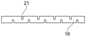
Fig. 4 and 5 illustrate another embodiment of a stent 10 having a flexible proximal section 16. In contrast to the embodiment illustrated in fig. 1 and 3, this flexibility is not provided by the materials used or by a separate process, but by the shape of the proximal section 16. In one embodiment, the proximal section has a plurality of openings 21 through the sidewall 19. In one embodiment, the openings are transverse slits, that is, slits arranged in a plane perpendicular to the longitudinal axis of the proximal region 16. The presence of these openings has the effect of allowing the proximal region to bend, which allows it to easily follow the curve of the ureter, in particular when relative movements of the ureter and the stent occur.
In one embodiment, the flexibility of the proximal section 16 is provided as a combination of its shape and by selection of materials. In one embodiment, a plurality of transverse openings 21 are formed in the proximal section 16 made of flexible material.
In various embodiments, the wire 17 or suture is configured to be secured to the proximal section 16 or to the ureteral section 15. The advantages of this fixation are the same as those already described with reference to the embodiment in fig. 1 and 3.
In the embodiment illustrated in fig. 6 and 7, the proximal section 16 is cylindrical and comprises a conical inner recess 22. This recess has an axis which coincides with the longitudinal axis of the cylinder. The thickness of the side walls 19 forming the proximal section 16 decreases in a direction towards the tail of the stent. In this way, the end of the proximal section opposite the ureteral section has a very small thickness and therefore a high flexibility. Thus, the proximal section can easily follow the movements of the ureter.
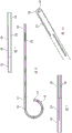
Fig. 8, 9 and 10 show an embodiment in which the proximal end region 16 has a plurality of through openings made in the form of a plurality of longitudinal slits 23 through the side wall 19. These longitudinal slits 23 allow the proximal region 16 to be easily deformed so as to follow the shape of the ureter. In one embodiment, the slits 23 do not extend all the way to the end of the proximal region 16, meaning that the end forms a complete loop.
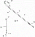
In one embodiment shown in fig. 11, 12 and 13, the proximal section comprises a plurality of through openings made in the form of a plurality of longitudinal slits 23'. However, at least some of these slits extend all the way to the caudal end of the stent in such a way that tongues 24 are formed in the proximal section. The tail end thus has a slit ring-like shape. The proximal section 16 is flexible and can be adapted to the shape of the ureter.
In one embodiment, the wire is attached to the proximal section, more precisely to one of the tongues 24. In one embodiment, more than one wire is attached in such a way that all tongues of this proximal section are connected to the wires forming the tail of the stent. This has the advantage of allowing the tongues to float in the ureter when the stent is placed in the patient in use, while also bringing them together when the tail of the stent is pulled to extract it from the patient.
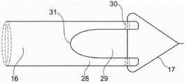
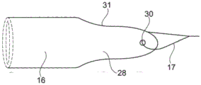
In one embodiment illustrated in fig. 17A-17B and 18A-18B, the proximal section 16 of the stent includes one or more openings or slits 29 and forms one or more tongues 28. In many embodiments, two or more openings or slits 29 are distributed such that two or more tongues 28 describe an equally large arcuate portion. In one embodiment, the proximal section 16 includes a single (one and only one) tongue 28 that provides flexibility.
In one embodiment shown in fig. 19A-19C, the proximal section 16 of the stent includes two tongues 28 separated by a plurality of openings or slits 29. In one embodiment, the proximal section 16 is provided with a plurality of openings 29 having a proximal section 16 that reflects the shape of an "enca hat"/"florian rimless hat (Phyrgian hat)".
In one embodiment, the profile 31 of one or more tongues 28 is rounded and may additionally be rounded towards the tail end of the proximal section 16, thereby providing a smooth shape with flexibility that can adapt to the shape of the ureter, thereby helping to remove patient discomfort. In one embodiment, the thread 17 is attached to the tongues 28 by one or more threading passages 30. Fig. 19C also shows the longitudinal channel 18 of the stent.
In one embodiment shown in fig. 14 and 15, the proximal section 16 of the stent is formed by a helix 25. This helical shape allows for flexing of the proximal section and thus provides high flexibility. By means of the helical shape, the stent can follow the curve of the patient's ureter. In one embodiment, the tail 12 of the stent is attached to one of the helical turns of the proximal section 16. The helical turns of the proximal region may be unwound to facilitate stent withdrawal. In one embodiment comprising a helical shape, the wire is secured to the ureteral section 15 of the stent.
If it is not desired to unwind the helix during withdrawal of the stent, in one embodiment, the wire is secured to several or all of the turns of the helix 25 forming the proximal section. This may preserve flexibility while avoiding excessive deformation of the stent.
In one embodiment, two wires are provided, one wire being fixed to the proximal section 16 and the other being fixed to the ureteral section 15. The wire secured to the proximal section is capable of guiding urine during use of the stent and guiding the proximal section during withdrawal of the stent. The wire secured to the ureteral section may contract the body of the stent without deforming it, and may also limit deformation of the proximal section during withdrawal.
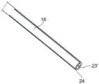
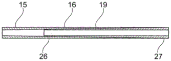
In one embodiment shown in fig. 16, the proximal section 16 is produced, for example, by co-extrusion of two materials having different degrees of flexibility. The thickness of the first material 26, which has a defined flexibility factor and is used to form the ureteral section 15, decreases in the direction of the tail end of the stent, while the thickness of the second material 27, which has a flexibility factor lower than that of the first material, increases in the direction of the tail end of the stent in such a way that the total thickness of the two materials remains constant. In other words, a less flexible material is gradually changed to a more flexible material in the direction of the free (tail) end of the stent.
A ureteral stent has been described which allows the drainage of urine from a patient while at the same time preventing the backflow of urine in the flow direction towards the kidneys. The stent is configured for placement to allow stones to be more easily expelled. The stent is barely perceptible to the patient on the body due to the flexibility of the proximal section. The wire is delicate and flexible so that it is almost ignored by the patient.
Detailed description of the preferred embodiments
A. A ureteral stent, comprising:
a body having a kidney region configured for placement in a kidney of a patient, a ureter region, and a proximal region, the ureter region being connected to the kidney region and configured for placement in a ureter of a patient, the proximal region being connected to the ureter region and located proximal to the body; and
a tail comprising a wire, the wire being connected to the proximal end of the body of the stent; wherein the proximal region is tubular and is provided with a first flexibility which is greater than a second flexibility of the ureteral region of the stent.
B. The ureteral stent according to embodiment a, wherein the proximal region of the stent comprises a material that is more flexible than the material forming the ureteral region of the stent.
C. The ureteral stent according to embodiment B, wherein the proximal region of the stent is made of two materials each having a different flexibility, and the proximal region has a longitudinal channel of constant diameter defining a sidewall of constant thickness.
D. The ureteral stent according to embodiment C, wherein a first material of the materials is less flexible than a second material of the two materials, and a thickness of the first material decreases toward a tail of the stent and a thickness of the second material increases toward the tail of the stent.
E. The ureteral stent according to embodiment a, wherein the proximal region includes a plurality of through openings.
F. The ureteral stent according to embodiment D, wherein the through openings are slits.
G. The ureteral stent according to embodiment F, wherein the slits extend in the longitudinal direction of the proximal region.
H. The ureteral stent according to embodiment F, wherein the slits extend in a transverse direction of the proximal region.
I. The ureteral stent according to embodiment E, wherein the through openings are holes.
J. The ureteral stent according to embodiment C, wherein the proximal region has a conical internal recess such that the thickness of the sidewall decreases toward the tail of the stent.
K. The ureteral stent according to embodiment a, wherein the proximal region is configured to be helical in shape.
L. the ureteral stent according to embodiment C, wherein the proximal region comprises longitudinal recesses formed in the thickness of the sidewall.
M. the ureteral stent according to embodiment a, wherein the proximal region has a slit ring-shaped cross-section.
The ureteral stent according to embodiment a, wherein the tail is connected to the proximal region.
O. the ureteral stent according to embodiment a, wherein the tail is connected to the ureteral region.
P. the ureteral stent according to embodiment a, wherein the body portion of the stent on the proximal region has a thickness equal to or lower than 200 nmm2The coefficient of flexibility of (a).
Ureteral stent (10) having a body (11) and a tail (12), the body (11) having a kidney region (13), a ureter region (15), and a proximal region (16), the kidney region being intended to be placed in a kidney (R) of a patient, the ureter region being intended to be placed in at least a portion of a ureter (U) of said patient, the proximal region being arranged at a proximal end of the stent body (11), the tail (12) having at least one wire (17) intended to terminate in a bladder (V) of said patient, characterized in that said proximal region (16) is tubular, has a cylindrical shape, and has a circular cross-section, and in that this proximal region (16) has a flexibility greater than that of the ureter region (15) of the stent.
R. ureteral stent according to embodiment Q, characterized in that the proximal region (16) of the stent is made of at least one material which is more flexible than the material forming the ureteral region (15) of the stent.
S. ureteral stent according to embodiment R, characterized in that the proximal region (16) of the stent is made of two materials with different flexibilities, in that this proximal region (16) has a longitudinal channel of constant diameter defining a lateral wall (19) of constant thickness, in that the amount of material of the less flexible material decreases towards the tail of the stent, while the amount of material of the more flexible material increases towards the tail of the stent.
T. the ureteral stent according to any of the embodiments Q to S, characterized in that the proximal region (16) has a shape which gives it a greater flexibility than the ureteral region (15).
U. ureteral stent according to embodiment T, characterized in that the proximal region (16) has a plurality of through openings.
V. the ureteral stent according to embodiment U, characterized in that said through openings are slits (23, 23').
W. the ureteral stent according to embodiment V, characterized in that the slits (23, 23') are longitudinal.
X. the ureteral stent according to embodiment V, wherein the slit is transverse.
Y. the ureteral stent according to embodiment U, wherein the through opening is a hole.
The ureteral stent according to embodiment S or T, characterized in that the proximal region (16) has an internal conical recess (22) so that the thickness of the side wall (19) decreases towards the tail of the stent.
A ureteral stent as claimed in embodiment Q, characterized in that the proximal region (16) is formed by a helix (25).
BB. the ureteral stent according to embodiment Q, characterized in that the proximal region (16) has longitudinal recesses formed in the thickness of the side wall (19).
The ureteral stent according to embodiment Q, characterized in that the proximal region (16) has a slit ring-shaped cross-section.
DD. the ureteral stent according to embodiment Q, characterized in that the tail (12) is rigidly connected to the proximal region (16).
Ureteral stent according to embodiment Q or DD, characterized in that the tail (12) is rigidly connected to the ureteral region (15).
FF. the ureteral stent according to any of the preceding embodiments Q to EE, characterized in that the proximal region (16) has a flexibility coefficient lower than 200N mm 2.
Method for producing a ureteral stent according to embodiment Q, characterized in that the proximal region (16) is subjected to a treatment that makes it more flexible than the ureteral region (15).
HH. the method of production according to embodiment GG, characterized in that the ureteral region (15) is subjected to a treatment which makes it less flexible than the proximal region (16).
A method of production according to embodiment GG or HH wherein the treatment is a chemical treatment.
A method of production according to embodiment GG or HH, wherein the treatment is a heat treatment.
Claims (7)
1. A ureteral stent (10), comprising:
a body (11) having a kidney section (13) configured for placement in a kidney of a patient, a ureteral section (15) connected to the kidney section (13) and configured for placement in a ureter of a patient, and a proximal section (16), the proximal section (16) being connected to the ureteral section (15) at a proximal end of the body (11), and the proximal section being arranged at a proximal end of the body (11); and
a tail (12) comprising a wire (17) connected to the proximal end of the body (11) of the stent (10); wherein the proximal section (16) is tubular and is provided with a first flexibility which is greater than a second flexibility of the ureteral section (15) of the stent, characterized in that,
the tubular proximal section (16) is configured in a helical shape (25).
2. The ureteral stent according to claim 1, wherein the proximal section (16) of the stent (10) comprises a material that is more flexible than the material forming the ureteral section (15) of the stent (10).
3. The ureteral stent according to claim 2, wherein the proximal section (16) of the stent (10) is made of two materials of different flexibility, and the proximal section (16) has a longitudinal channel (18) of constant diameter defined by a side wall (19) of constant thickness.
4. The ureteral stent according to claim 3, wherein a first material of the two materials is less flexible than a second material of the two materials, and the thickness of the first material decreases towards the tail (12) of the stent (10) and the thickness of the second material increases towards the tail (12) of the stent (10).
5. The ureteral stent according to claim 1, wherein the tail (12) is rigidly connected with the proximal section (16).
6. The ureteral stent according to claim 1, wherein the tail (12) is rigidly connected to the ureteral section (15).
7. The ureteral stent according to claim 1, wherein the body portion of the stent on the proximal section (16) has a value equal to or lower than 200N/mm2The coefficient of flexibility of (a).
Applications Claiming Priority (5)
| Application Number | Priority Date | Filing Date | Title |
|---|---|---|---|
| EP14290105.7 | 2014-04-11 | ||
| EP14290105 | 2014-04-11 | ||
| EP14178201.1A EP2977074B1 (en) | 2014-07-23 | 2014-07-23 | A ureteral stent |
| EP14178201.1 | 2014-07-23 | ||
| CN201580018865.3A CN106163604B (en) | 2014-04-11 | 2015-04-10 | Ureter bracket |
Related Parent Applications (1)
| Application Number | Title | Priority Date | Filing Date |
|---|---|---|---|
| CN201580018865.3A Division CN106163604B (en) | 2014-04-11 | 2015-04-10 | Ureter bracket |
Publications (2)
| Publication Number | Publication Date |
|---|---|
| CN110711306A CN110711306A (en) | 2020-01-21 |
| CN110711306B true CN110711306B (en) | 2022-02-22 |
Family
ID=52991405
Family Applications (2)
| Application Number | Title | Priority Date | Filing Date |
|---|---|---|---|
| CN201911081095.3A Expired - Fee Related CN110711306B (en) | 2014-04-11 | 2015-04-10 | Ureter bracket |
| CN201580018865.3A Expired - Fee Related CN106163604B (en) | 2014-04-11 | 2015-04-10 | Ureter bracket |
Family Applications After (1)
| Application Number | Title | Priority Date | Filing Date |
|---|---|---|---|
| CN201580018865.3A Expired - Fee Related CN106163604B (en) | 2014-04-11 | 2015-04-10 | Ureter bracket |
Country Status (4)
| Country | Link |
|---|---|
| US (1) | US20170105833A1 (en) |
| JP (2) | JP2017510370A (en) |
| CN (2) | CN110711306B (en) |
| WO (1) | WO2015154781A1 (en) |
Families Citing this family (4)
| Publication number | Priority date | Publication date | Assignee | Title |
|---|---|---|---|---|
| US10226606B2 (en) * | 2014-04-10 | 2019-03-12 | C.R. Bard, Inc. | Ureteral stents |
| CN106730240A (en) * | 2016-11-16 | 2017-05-31 | 王占华 | Bionic urethral catheterization pipe and its application method |
| CN110721391A (en) * | 2019-09-30 | 2020-01-24 | 深圳泰睿仕医疗科技有限公司 | Disposable ureter catheterization support tube |
| CN116019602A (en) * | 2021-07-23 | 2023-04-28 | 上海火点医疗器械有限公司 | Ureteral stent |
Citations (4)
| Publication number | Priority date | Publication date | Assignee | Title |
|---|---|---|---|---|
| CN2408894Y (en) * | 2000-01-06 | 2000-12-06 | 马建新 | Implantation type ureter internal supporter |
| WO2002089893A1 (en) * | 2001-05-04 | 2002-11-14 | Scimed Life Systems, Inc. | Drainage devices and methods |
| CN203029785U (en) * | 2013-01-29 | 2013-07-03 | 深圳市康医博科技发展有限公司 | Hard tip type pigtail-shaped flow guiding catheter |
| CN105163792A (en) * | 2012-12-19 | 2015-12-16 | 班诺特·福格特 | Improved ureteral stent and method for treating urological problems |
Family Cites Families (13)
| Publication number | Priority date | Publication date | Assignee | Title |
|---|---|---|---|---|
| US4250072A (en) * | 1979-05-18 | 1981-02-10 | Flynn Vincent J | Radiopaque polyurethane resin compositions |
| US4351339A (en) * | 1981-04-14 | 1982-09-28 | Sneider Vincent R | Tampon with a protective accordion-style cover |
| US6991614B2 (en) * | 1995-11-07 | 2006-01-31 | Boston Scientific Scimed, Inc. | Ureteral stent for improved patient comfort |
| DE69637049T2 (en) * | 1995-11-07 | 2007-12-27 | Boston Scientific Ltd., St. Michael | Ureteral stent with small bladder endings |
| US6709465B2 (en) * | 1999-03-18 | 2004-03-23 | Fossa Medical, Inc. | Radially expanding ureteral device |
| GB0012764D0 (en) * | 2000-05-26 | 2000-07-19 | Tayside University Hospitals N | G-stent |
| US7381198B2 (en) * | 2000-08-23 | 2008-06-03 | Revascular Therapeutics, Inc. | Steerable distal support system |
| US6719804B2 (en) * | 2001-04-02 | 2004-04-13 | Scimed Life Systems, Inc. | Medical stent and related methods |
| US20040073283A1 (en) * | 2001-12-21 | 2004-04-15 | Ewers Richard C. | Stent delivery system and method |
| US7470247B2 (en) * | 2004-04-26 | 2008-12-30 | Gyrus Acmi, Inc. | Ureteral stent |
| US9585989B2 (en) * | 2006-09-19 | 2017-03-07 | Boston Scientific Scimed, Inc. | Ureteral stent having variable hardness |
| US20120095566A1 (en) * | 2010-10-18 | 2012-04-19 | Boston Scientific Scimed, Inc. | Flexible ureteral stent |
| US9254203B2 (en) * | 2012-08-20 | 2016-02-09 | Boston Scientific Scimed, Inc. | Delivery device |
-
2015
- 2015-04-10 US US15/302,015 patent/US20170105833A1/en not_active Abandoned
- 2015-04-10 JP JP2016560977A patent/JP2017510370A/en active Pending
- 2015-04-10 CN CN201911081095.3A patent/CN110711306B/en not_active Expired - Fee Related
- 2015-04-10 CN CN201580018865.3A patent/CN106163604B/en not_active Expired - Fee Related
- 2015-04-10 WO PCT/DK2015/050087 patent/WO2015154781A1/en active Application Filing
-
2020
- 2020-01-24 JP JP2020000236U patent/JP3226297U/en active Active
Patent Citations (4)
| Publication number | Priority date | Publication date | Assignee | Title |
|---|---|---|---|---|
| CN2408894Y (en) * | 2000-01-06 | 2000-12-06 | 马建新 | Implantation type ureter internal supporter |
| WO2002089893A1 (en) * | 2001-05-04 | 2002-11-14 | Scimed Life Systems, Inc. | Drainage devices and methods |
| CN105163792A (en) * | 2012-12-19 | 2015-12-16 | 班诺特·福格特 | Improved ureteral stent and method for treating urological problems |
| CN203029785U (en) * | 2013-01-29 | 2013-07-03 | 深圳市康医博科技发展有限公司 | Hard tip type pigtail-shaped flow guiding catheter |
Also Published As
| Publication number | Publication date |
|---|---|
| JP2017510370A (en) | 2017-04-13 |
| CN106163604B (en) | 2019-11-05 |
| US20170105833A1 (en) | 2017-04-20 |
| CN110711306A (en) | 2020-01-21 |
| JP3226297U (en) | 2020-06-18 |
| WO2015154781A1 (en) | 2015-10-15 |
| CN106163604A (en) | 2016-11-23 |
Similar Documents
| Publication | Publication Date | Title |
|---|---|---|
| US10500073B2 (en) | Ureteral stent for placement in a kidney and bladder | |
| US7396366B2 (en) | Ureteral stent with conforming retention structure | |
| JP3226297U (en) | Ureteral stent | |
| US8192500B2 (en) | Ureteral stent | |
| CN109906100B (en) | Controlled extension stent | |
| JP2005312898A (en) | Improved stent | |
| JP7212989B2 (en) | ureteral stent | |
| CN107847312B (en) | Stent and method of use | |
| JP6898372B2 (en) | Ureteral stent | |
| EP3517162B1 (en) | A ureteral stent | |
| EP2977075B1 (en) | A Ureteral Stent | |
| WO2018061021A1 (en) | A ureteral stent | |
| WO2017193120A1 (en) | Ureteral stent |
Legal Events
| Date | Code | Title | Description |
|---|---|---|---|
| PB01 | Publication | ||
| PB01 | Publication | ||
| SE01 | Entry into force of request for substantive examination | ||
| SE01 | Entry into force of request for substantive examination | ||
| GR01 | Patent grant | ||
| GR01 | Patent grant | ||
| CF01 | Termination of patent right due to non-payment of annual fee |
Granted publication date: 20220222 |