CN110678952B - Circuit breaker and safety circuit with same - Google Patents
Circuit breaker and safety circuit with same Download PDFInfo
- Publication number
- CN110678952B CN110678952B CN201880033650.2A CN201880033650A CN110678952B CN 110678952 B CN110678952 B CN 110678952B CN 201880033650 A CN201880033650 A CN 201880033650A CN 110678952 B CN110678952 B CN 110678952B
- Authority
- CN
- China
- Prior art keywords
- circuit breaker
- piece
- movable
- contact
- housing
- Prior art date
- Legal status (The legal status is an assumption and is not a legal conclusion. Google has not performed a legal analysis and makes no representation as to the accuracy of the status listed.)
- Active
Links
Images


Classifications
-
- H—ELECTRICITY
- H01—ELECTRIC ELEMENTS
- H01M—PROCESSES OR MEANS, e.g. BATTERIES, FOR THE DIRECT CONVERSION OF CHEMICAL ENERGY INTO ELECTRICAL ENERGY
- H01M10/00—Secondary cells; Manufacture thereof
- H01M10/42—Methods or arrangements for servicing or maintenance of secondary cells or secondary half-cells
- H01M10/425—Structural combination with electronic components, e.g. electronic circuits integrated to the outside of the casing
-
- H—ELECTRICITY
- H01—ELECTRIC ELEMENTS
- H01M—PROCESSES OR MEANS, e.g. BATTERIES, FOR THE DIRECT CONVERSION OF CHEMICAL ENERGY INTO ELECTRICAL ENERGY
- H01M50/00—Constructional details or processes of manufacture of the non-active parts of electrochemical cells other than fuel cells, e.g. hybrid cells
- H01M50/50—Current conducting connections for cells or batteries
- H01M50/572—Means for preventing undesired use or discharge
- H01M50/574—Devices or arrangements for the interruption of current
- H01M50/581—Devices or arrangements for the interruption of current in response to temperature
-
- H—ELECTRICITY
- H01—ELECTRIC ELEMENTS
- H01H—ELECTRIC SWITCHES; RELAYS; SELECTORS; EMERGENCY PROTECTIVE DEVICES
- H01H1/00—Contacts
- H01H1/58—Electric connections to or between contacts; Terminals
- H01H1/5805—Connections to printed circuits
-
- H—ELECTRICITY
- H01—ELECTRIC ELEMENTS
- H01H—ELECTRIC SWITCHES; RELAYS; SELECTORS; EMERGENCY PROTECTIVE DEVICES
- H01H37/00—Thermally-actuated switches
- H01H37/02—Details
- H01H37/04—Bases; Housings; Mountings
-
- H—ELECTRICITY
- H01—ELECTRIC ELEMENTS
- H01H—ELECTRIC SWITCHES; RELAYS; SELECTORS; EMERGENCY PROTECTIVE DEVICES
- H01H37/00—Thermally-actuated switches
- H01H37/02—Details
- H01H37/32—Thermally-sensitive members
- H01H37/52—Thermally-sensitive members actuated due to deflection of bimetallic element
- H01H37/54—Thermally-sensitive members actuated due to deflection of bimetallic element wherein the bimetallic element is inherently snap acting
-
- H—ELECTRICITY
- H01—ELECTRIC ELEMENTS
- H01H—ELECTRIC SWITCHES; RELAYS; SELECTORS; EMERGENCY PROTECTIVE DEVICES
- H01H1/00—Contacts
- H01H1/50—Means for increasing contact pressure, preventing vibration of contacts, holding contacts together after engagement, or biasing contacts to the open position
- H01H1/504—Means for increasing contact pressure, preventing vibration of contacts, holding contacts together after engagement, or biasing contacts to the open position by thermal means
-
- H—ELECTRICITY
- H01—ELECTRIC ELEMENTS
- H01H—ELECTRIC SWITCHES; RELAYS; SELECTORS; EMERGENCY PROTECTIVE DEVICES
- H01H1/00—Contacts
- H01H1/58—Electric connections to or between contacts; Terminals
- H01H2001/5888—Terminals of surface mounted devices [SMD]
-
- H—ELECTRICITY
- H01—ELECTRIC ELEMENTS
- H01H—ELECTRIC SWITCHES; RELAYS; SELECTORS; EMERGENCY PROTECTIVE DEVICES
- H01H37/00—Thermally-actuated switches
- H01H37/02—Details
- H01H37/32—Thermally-sensitive members
- H01H37/52—Thermally-sensitive members actuated due to deflection of bimetallic element
- H01H37/54—Thermally-sensitive members actuated due to deflection of bimetallic element wherein the bimetallic element is inherently snap acting
- H01H2037/5463—Thermally-sensitive members actuated due to deflection of bimetallic element wherein the bimetallic element is inherently snap acting the bimetallic snap element forming part of switched circuit
-
- H—ELECTRICITY
- H01—ELECTRIC ELEMENTS
- H01H—ELECTRIC SWITCHES; RELAYS; SELECTORS; EMERGENCY PROTECTIVE DEVICES
- H01H37/00—Thermally-actuated switches
- H01H37/02—Details
- H01H37/32—Thermally-sensitive members
- H01H37/52—Thermally-sensitive members actuated due to deflection of bimetallic element
- H01H37/54—Thermally-sensitive members actuated due to deflection of bimetallic element wherein the bimetallic element is inherently snap acting
- H01H37/5427—Thermally-sensitive members actuated due to deflection of bimetallic element wherein the bimetallic element is inherently snap acting encapsulated in sealed miniaturised housing
- H01H37/5436—Thermally-sensitive members actuated due to deflection of bimetallic element wherein the bimetallic element is inherently snap acting encapsulated in sealed miniaturised housing mounted on controlled apparatus
-
- H—ELECTRICITY
- H01—ELECTRIC ELEMENTS
- H01M—PROCESSES OR MEANS, e.g. BATTERIES, FOR THE DIRECT CONVERSION OF CHEMICAL ENERGY INTO ELECTRICAL ENERGY
- H01M2200/00—Safety devices for primary or secondary batteries
- H01M2200/10—Temperature sensitive devices
-
- H—ELECTRICITY
- H01—ELECTRIC ELEMENTS
- H01M—PROCESSES OR MEANS, e.g. BATTERIES, FOR THE DIRECT CONVERSION OF CHEMICAL ENERGY INTO ELECTRICAL ENERGY
- H01M2220/00—Batteries for particular applications
- H01M2220/20—Batteries in motive systems, e.g. vehicle, ship, plane
-
- Y—GENERAL TAGGING OF NEW TECHNOLOGICAL DEVELOPMENTS; GENERAL TAGGING OF CROSS-SECTIONAL TECHNOLOGIES SPANNING OVER SEVERAL SECTIONS OF THE IPC; TECHNICAL SUBJECTS COVERED BY FORMER USPC CROSS-REFERENCE ART COLLECTIONS [XRACs] AND DIGESTS
- Y02—TECHNOLOGIES OR APPLICATIONS FOR MITIGATION OR ADAPTATION AGAINST CLIMATE CHANGE
- Y02E—REDUCTION OF GREENHOUSE GAS [GHG] EMISSIONS, RELATED TO ENERGY GENERATION, TRANSMISSION OR DISTRIBUTION
- Y02E60/00—Enabling technologies; Technologies with a potential or indirect contribution to GHG emissions mitigation
- Y02E60/10—Energy storage using batteries
Abstract
A circuit breaker (1) is provided with: a fixed contact (20); a movable piece (4) extending in a first direction (D1); a thermally responsive element (5); a case (7) that houses the movable piece (4) and the thermally responsive element (5); and a terminal piece (2) having a part protruding from the case (7) and electrically connected to an external circuit. The terminal piece (2) has: a first portion (21) and a second portion (22) having different heights from the bottom surface of the housing (7); a first bending section (23a) that bends in a first bending direction; and a second bending portion (23b) which is bent in a second bending direction opposite to the first bending direction. The first curved portion (23a) and the second curved portion (23b) extend parallel to the first direction (D1).
Description
Technical Field
The present invention relates to a small-sized circuit breaker or the like such as a secondary battery pack built in an electrical device.
Background
Conventionally, circuit breakers have been used as protection devices (safety circuits) for secondary batteries, motors, and the like of various electrical devices. When an abnormality occurs, for example, when the temperature of the secondary battery rises excessively during charge and discharge, or when an overcurrent flows through a motor or the like of an apparatus such as an automobile or a home electric appliance, the circuit breaker interrupts the current to protect the secondary battery or the motor. In order to ensure safety of equipment, a circuit breaker used as such a protection device is required to accurately operate (have good temperature characteristics) following a temperature change and to have a stable resistance value when energized.
The circuit breaker includes a thermally responsive element that operates in response to a temperature change to conduct or interrupt a current. A circuit breaker using a bimetal as a thermally responsive element is shown in patent document 1. The bimetal is an element that: and an element in which two kinds of plate-like metal materials having different thermal expansion coefficients are laminated, and the shape is changed according to a temperature change, thereby controlling the conduction state of the contact. The circuit breaker disclosed in this document is configured to house components such as a fixed piece, a terminal piece, a movable piece, a thermally responsive element, and a PTC thermistor in a case, and the terminals of the fixed piece and the terminal piece protrude from the case and are used for connection to a circuit of an electrical device.
Documents of the prior art
Patent document
Patent document 1: japanese patent laid-open publication No. 2016-035822
Disclosure of Invention
Problems to be solved by the invention
When the circuit breaker is used as a protection device for a secondary battery or the like provided in an electric apparatus such as a personal notebook computer, a tablet-type portable information terminal apparatus, or a thin multi-function portable telephone called a smartphone, miniaturization is required in addition to the above-described safety assurance. In particular, in recent portable information terminal devices, users' intention to be small (thin) is increasing, and a trend of designing small devices to ensure design superiority is remarkable in devices newly introduced by companies. Under such circumstances, further miniaturization is strongly demanded also for a circuit breaker mounted together with a secondary battery as one component constituting a portable information terminal device.
The present invention has been made to solve the above problems, and an object thereof is to provide a circuit breaker that can be easily miniaturized.
Means for solving the problems
In order to achieve the above object, the present invention relates to a circuit breaker including: a fixed contact; a movable piece having an elastic portion that extends in a first direction and elastically deforms, a movable contact at one end of the elastic portion, and the movable contact being pressed against the fixed contact to bring the movable contact into contact with the fixed contact; a thermally responsive element that deforms with a change in temperature, thereby operating the movable piece so that the movable contact is separated from the fixed contact; a case that houses the movable piece and the heat-responsive element; and a terminal piece, a part of which protrudes from the housing and is electrically connected to an external circuit, the terminal piece including: a first portion having a first height from a bottom surface of the housing; a second portion having a second height from the bottom surface of the housing, the second height being lower than the first height, and connected to the external circuit; a third portion connecting the first portion and the second portion; a first curved portion that is curved in a first curved direction in a region where the first portion and the third portion intersect; and a second bent portion that is bent in a second bending direction opposite to the first bending direction in a region where the second portion and the third portion intersect, the first bent portion and the second bent portion extending parallel to the first direction.
In the circuit breaker according to the present invention, it is preferable that the fixed contact is formed in the first portion.
In the circuit breaker according to the present invention, it is preferable that the other end of the elastic portion is electrically connected to the first portion.
In the circuit breaker according to the present invention, it is preferable that the case has an internal space for accommodating the movable piece and the thermally responsive element, the first portion is exposed to the internal space on a first surface on a side opposite to the bottom surface, and the second portion is embedded in the case without being exposed to the internal space on the first surface.
In the circuit breaker according to the present invention, it is preferable that the second portion is exposed to the outside of the case on a second surface of the bottom surface side.
In the circuit breaker according to the present invention, it is preferable that the terminal piece has a first protruding portion extending from the first portion in the first direction and protruding to the outside of the case.
In the circuit breaker according to the present invention, it is preferable that the terminal piece has a second protruding portion extending from the second portion in a second direction orthogonal to the first direction and protruding to the outside of the case.
In the circuit breaker according to the present invention, it is preferable that the second protruding portion is disposed at both ends of the terminal piece in the second direction.
The safety circuit for electrical equipment according to the present invention is characterized by including the breaker.
Effects of the invention
According to the breaker of the present invention, the terminal piece has the first bent portion bent in the first bending direction and the second bent portion bent in the second bending direction, and the first bent portion and the second bent portion are arranged to have different heights, and the first bent portion and the second bent portion extend in parallel to the elastic portion of the movable piece. Thus, the second portion extends from the first portion in a direction perpendicular to the first direction, and is connected to an external circuit. Therefore, the length dimension of the first direction of the circuit breaker can be reduced.
Drawings
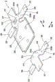
Fig. 1 is a perspective view showing a schematic configuration of a circuit breaker according to an embodiment of the present invention before assembly.
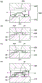
Fig. 2 is a sectional view showing the breaker in a normal charged or discharged state.
Fig. 3 is a sectional view of the breaker illustrating an overcharged state, an abnormal state, and the like.
Fig. 4 is a perspective view showing a structure of a terminal plate of the circuit breaker.
Fig. 5 is a sectional view showing a process of molding a case body of the circuit breaker.
Fig. 6 is a perspective view of the circuit breaker as viewed from the bottom surface side.
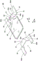
Fig. 7 is a perspective view of a circuit breaker according to another embodiment of the present invention, as viewed from the bottom surface side.
Fig. 8 is a perspective view showing a structure of a terminal plate of the circuit breaker.
Fig. 9 is a circuit diagram of a safety circuit including the circuit breaker according to the present invention.
Detailed Description
(first embodiment)
A circuit breaker according to an embodiment of the first invention of the present invention will be described with reference to the drawings. Fig. 1 to 4 show the structure of the circuit breaker. The circuit breaker 1 includes a pair of terminal pieces 2 and 3, a part of which is exposed to the outside from a case 7. The circuit breaker 1 constitutes a main part of a safety circuit of an electric apparatus by electrically connecting the terminal pieces 2 and 3 to an external circuit (not shown).
The circuit breaker 1 includes: a fixed contact 20; terminal pieces 2, 3; a movable piece 4 having a movable contact 41 at a front end portion; a thermally responsive element 5 that deforms with a change in temperature; a PTC (Positive Temperature Coefficient) thermistor 6; and a case 7 for housing the terminal pieces 2 and 3, the movable piece 4, the thermally responsive element 5, and the PTC thermistor 6. The housing 7 is constituted by a housing main body (first housing) 71, a cover member (second housing) 81 attached to an upper surface of the housing main body 71, and the like.
The fixed contact 20 is formed by cladding, plating, coating, or the like of a material having good conductivity, such as a copper-silver alloy, a gold-silver alloy, or the like, in addition to silver, nickel, and a nickel-silver alloy. The fixed contacts 20 are formed at positions facing the movable contacts 41 of the terminal pieces 2, and are exposed to the housing recess 73 of the housing main body 71 from a part of the opening 73a formed in the housing main body 71.
The terminal pieces 2 and 3 are formed by, for example, pressing a metal plate (including a metal plate of copper-titanium alloy, copper nickel zinc, brass, or the like in addition to the metal plate) mainly composed of copper or the like, and are embedded in the case main body 71 by insert molding.
The terminal piece 2 includes: a first portion 21 having a first height h21 from the bottom surface of the housing main body 71; and a second portion 22 having a second height h22 from the bottom surface of the case main body 71 and connected to an external circuit. The first portion 21 and the second portion 22 are arranged in parallel with the bottom surface of the housing main body 71. The second height h22 is lower than the first height h21, and in the present embodiment, the bottom surface of the second portion 22 coincides with the bottom surface of the case main body 71.
The fixed contact 20 is formed in the first portion 21. The terminal piece 2 has a step bent portion 25 bent in a step shape (crank shape in side view) and a support portion 26 supporting the PTC thermistor 6. The stepped bent portion 25 connects the first portion 21 and the support portion 26, and the first portion 21 and the support portion 26 are arranged at different heights. The PTC thermistor 6 is placed on a projection (bump) 26a formed at 3 of the support portion 26 and is supported by the projection 26 a.
In the present application, unless otherwise specified, a surface of the terminal piece 2 on which the fixed contacts 20 are formed (i.e., an upper surface in fig. 1) is described as a first surface 2U, and a bottom surface on the opposite side is described as a second surface 2L (see fig. 4). The same applies to other components, such as the terminal plate 3, the movable plate 4, the heat responsive element 5, and the case 7.
The second portion 22 is exposed to the outside of the housing 7 on the second surface 2L. Thereby, the second portion 22 can be electrically connected to an external circuit. The connection of the second portion 22 to the external circuit is, for example, by soldering. The second portion 22 is soldered with a pad of an external circuit in a region including the second face 2L of the second portion 22. Therefore, the solder can also be wound around the side surface of the second portion 22 protruding from the housing 7 and the first surface 2U.
The terminal piece 3 has: a first portion 31 having a first height h31 from the bottom surface of the housing main body 71; and a second portion 32 having a second height h32 from the bottom surface of the case main body 71 and connected to an external circuit. The first portion 31 and the second portion 32 are disposed parallel to the bottom surface of the housing main body 71. The second height h32 is lower than the first height h31, and in the present embodiment, the bottom surface of the second portion 32 coincides with the bottom surface of the case main body 71.
The first portion 31 of the terminal piece 3 is electrically connected to the movable piece 4 on the first surface 3U. The first surface 3U of the first portion 31 is exposed to the housing recess 73 of the housing main body 71 from the opening 73b provided in the housing main body 71, and is electrically connected to the movable piece 4.
The second portion 32 is exposed to the outside of the housing 7 on the second surface 3L. Thereby, the second portion 32 can be electrically connected to an external circuit, as in the terminal piece 2.
The movable piece 4 is formed by pressing a plate-like metal material containing copper or the like as a main component. The movable piece 4 is formed in an arm shape symmetrical with respect to a center line in the longitudinal direction.
A movable contact 41 is formed at one end of the movable piece 4. The movable contact 41 is formed on the second surface of the movable piece 4 by a material similar to that of the fixed contact 20, and is joined to the tip end of the movable piece 4 by a method such as cladding or caulking in addition to welding.
At the other end of the movable piece 4, a connecting portion 42 electrically connected to the first portion 31 of the terminal piece 3 is formed. The first portion 31 of the terminal piece 3 and the connecting portion 42 of the movable piece 4 are fixedly attached by laser welding. The laser welding is a welding method in which a workpiece (in the present embodiment, the terminal piece 3 and the movable piece 4) is irradiated with a laser beam, and the workpiece is locally melted and solidified to join the workpieces to each other. A laser welding trace having a different form from a welding trace of another welding method (for example, resistance welding by joule heat) is formed on the surface of the workpiece irradiated with the laser.
The movable piece 4 has an elastic portion 43 between the movable contact 41 and the connecting portion 42. The elastic portion 43 extends from the connecting portion 42 toward the movable contact 41. Thus, the connection portion 42 is provided on the opposite side of the movable contact 41 with the elastic portion 43 interposed therebetween. In the present application, the longitudinal direction of the movable piece extending from the elastic portion 43 is defined as a first direction D1, and the lateral direction perpendicular to the first direction D1 is defined as a second direction D2.
The movable piece 4 is fixed by being fixedly attached to the first portion 31 of the terminal piece 3 at the connecting portion 42, and the movable contact 41 formed at the tip end thereof is pressed toward the fixed contact 20 and brought into contact with the fixed contact 21 by being elastically deformed by the elastic portion 43, whereby the terminal piece 2 and the movable piece 4 can be electrically conducted. Since movable plate 4 and terminal plate 3 are electrically connected to each other at first portion 31 and connecting portion 42, terminal plate 2 and terminal plate 3 can be electrically connected to each other.
The movable piece 4 is bent or folded by press working at the elastic portion 43. The degree of bending or bending is not particularly limited as long as the thermally responsive element 5 can be housed, and may be set as appropriate in consideration of the elastic force at the operating temperature and the recovery temperature, the pressing force of the contact, and the like. Further, a pair of projections (contact portions) 44a and 44b are formed on the second surface of the elastic portion 43 so as to face the thermally responsive element 5. The projections 44a and 44b are in contact with the thermally responsive element 5, and the deformation of the thermally responsive element 5 is transmitted to the elastic portion 43 via the projections 44a and 44b (see fig. 1 and 3).
The thermally responsive element 5 is formed by laminating thin plate materials having different thermal expansion coefficients in an initial shape in which the element is bent in an arc shape. When the operating temperature is reached due to overheating, the curved shape of the thermally responsive element 5 is warped in the opposite direction as the snap movement and is restored when it is lower than the restoration temperature due to cooling. The initial shape of the thermally responsive member 5 may be formed by a press working. The material and shape of the thermally responsive element 5 are not particularly limited as long as the elastic portion 43 of the movable piece 4 is pushed up by the reverse buckling operation of the thermally responsive element 5 at a desired temperature and the shape is restored by the elastic force of the elastic portion 43, but a rectangular shape is preferable from the viewpoint of productivity and efficiency of the reverse buckling operation, and a rectangular shape is preferable in order to push up the elastic portion 43 efficiently while being small in size. As the material of the thermally responsive element 5, a material obtained by laminating two materials having different thermal expansion coefficients, which are made of various alloys, is used in combination according to a desired condition, and for example, a copper-nickel-manganese alloy or a nickel-chromium-iron alloy is used on the high expansion side, and a copper-nickel-zinc alloy typified by an iron-nickel alloy, brass, stainless steel, or the like is used on the low expansion side.
The PTC thermistor 6 is disposed between the support portion 26 of the terminal piece 2 and the thermally responsive element 5. That is, the support portion 26 is located directly below the thermally responsive element 5 with the PTC thermistor 6 interposed therebetween. When the current between the terminal piece 2 and the movable piece 4 is cut off by the reverse warping operation of the thermally responsive element 5, the current flowing through the PTC thermistor 6 increases. The PTC thermistor 6 may be selected according to the requirements of the operating current, operating voltage, operating temperature, recovery temperature, and the like, as long as the resistance value thereof increases with an increase in temperature to limit the current, and the material and shape thereof are not particularly limited as long as the above characteristics are not impaired. In the present embodiment, a ceramic sintered body containing barium titanate, strontium titanate, or calcium titanate is used. In addition to the ceramic sintered body, a so-called polymer PTC in which a polymer contains conductive particles such as carbon may be used.
The case body 71 and the lid member 81 constituting the case 7 are molded from a thermoplastic resin such as flame-retardant polyamide, polyphenylene sulfide (PPS) having excellent heat resistance, Liquid Crystal Polymer (LCP), and polybutylene terephthalate (PBT). Materials other than the resin may be used as long as the properties equivalent to or higher than those of the above-described resin can be obtained.
The housing main body 71 is formed with a housing recess 73, and the housing recess 73 is an internal space for housing the movable piece 4, the thermo-responsive element 5, the PTC thermistor 6, and the like. The housing recess 73 has: openings 73a and 73b for accommodating the movable piece 4; an opening 73c for accommodating the movable piece 4 and the thermally responsive element 5; and an opening 73d for accommodating the PTC thermistor 6. The movable piece 4 assembled to the housing main body 71 and the end edge of the thermally responsive element 5 are respectively abutted by the frame formed inside the housing concave portion 73 and guided when the thermally responsive element 5 is warped in the reverse direction.
The cover member 81 is embedded with the cover sheet 9 by insert molding. The cover sheet 9 is formed by pressing a metal plate containing copper or the like as a main component or a metal plate such as stainless steel. As shown in fig. 2 and 3, the cover plate 9 appropriately abuts against the first surface of the movable piece 4 to restrict the movement of the movable piece 4, and contributes to the miniaturization of the circuit breaker 1 while improving the rigidity and strength of the cover member 81 and the case 7 serving as a housing. A resin is disposed on the outer surface side of the cover sheet 9.
As shown in fig. 1, the lid member 81 is attached to the case main body 71 so as to close the openings 73a, 73b, 73c, etc. of the case main body 71 in which the terminal pieces 2, 3, the movable piece 4, the thermally responsive element 5, the PTC thermistor 6, etc. are housed. The case body 71 and the lid member 81 are joined by, for example, ultrasonic welding. At this time, the case main body 71 and the lid member 81 are continuously joined over the entire periphery of the outer edge portions thereof, thereby improving the airtightness of the case 7. Thus, the internal space of the case 7 created by the housing recess 73 is sealed, and the movable piece 4, the thermally responsive element 5, the PTC thermistor 6, and other components can be protected by being blocked from the atmosphere outside the case 7.
Fig. 2 shows the operation of the circuit breaker 1 in a normal charging or discharging state. In a normal charged or discharged state, the thermally responsive element 5 maintains an original shape (before reverse warping). The cover sheet 9 is provided with a projection 91, and the projection 91 abuts against the top portion 43a of the movable sheet 4 and presses the top portion 43a toward the thermoresponsive element 5. The elastic portion 43 is elastically deformed by the pressing of the top portion 43a by the protrusion 91, and the movable contact 41 formed at the tip thereof is pressed toward the fixed contact 20 and brought into contact with the fixed contact 21. Thus, the terminal pieces 2 and 3 of the circuit breaker 1 are electrically connected to each other by the elastic portion 43 of the movable piece 4. The elastic portion 43 of the movable piece 4 is in contact with the thermally responsive element 5, and the movable piece 4, the thermally responsive element 5, the PTC thermistor 6, and the terminal piece 2 can be electrically connected as a circuit. However, since the resistance of the PTC thermistor 6 is overwhelmingly larger than the resistance of the movable piece 4, the current flowing through the PTC thermistor 6 is substantially negligible compared to the amount flowing through the fixed contact 20 and the movable contact 41.
Fig. 3 shows the operation of the circuit breaker 1 in an overcharged state, an abnormal state, or the like. When the high temperature state is caused by overcharge or abnormality, the thermally responsive element 5 having reached the operating temperature is warped reversely, the elastic portion 43 of the movable piece 4 is pushed up, and the fixed contacts 20 are separated from the movable contacts 41. The operating temperature of the thermally responsive element 5 when the thermally responsive element 5 deforms and pushes up the movable piece 4 in the breaker 1 is, for example, 70 to 90 ℃. At this time, the current flowing between the fixed contact 20 and the movable contact 41 is interrupted, and a minute leakage current flows through the thermally responsive element 5 and the PTC thermistor 6. As long as such a leakage current flows, the PTC thermistor 6 continues to generate heat, and the resistance value rapidly increases while the thermally responsive element 5 is maintained in the reverse warping state, so that no current flows through the path between the fixed contact 20 and the movable contact 41, and only the above-described small leakage current (constituting a self-holding circuit) exists. This leakage current can be used for other functions of the security device.
When the overcharged state is released or the abnormal state is eliminated, the heat generation of the PTC thermistor 6 is also stopped, and the thermally responsive element 5 returns to the recovery temperature and returns to the original shape. Then, the movable contact 41 and the fixed contact 20 are brought into contact again by the elastic force of the elastic portion 43 of the movable piece 4, and the circuit is released from the disconnected state and returns to the conductive state shown in fig. 2.
Fig. 4 shows the terminal pieces 2, 3. The structure of the terminal pieces 2 and 3 will be described in detail below.
The terminal piece 2 includes: the first and second portions 21 and 22; a third portion 23 connecting the first portion 21 and the second portion 22; a first curved portion 23a formed in a region where the first portion 21 and the third portion 23 intersect; and a second bent portion 23b formed in a region where the second portion 22 and the third portion 23 intersect.
The second portion 22 is provided with a pair. The second portions 22 are located on both sides in the second direction D2 with the first portions 21 therebetween. At the first bent portion 23a, the terminal piece 2 is bent in a first bending direction (peak shape) so that the first face 2U protrudes. At the second bent portion 23b, the terminal piece 2 is bent in the second bending direction (valley shape) so that the second face 2L protrudes. That is, the first bent portion 23a and the second bent portion 23b are bent in opposite bending directions. Thus, the first portion 21 and the second portion 22 are formed in a stepped shape having different heights with the third portion 23 interposed therebetween.
The first bent portion 23a and the second bent portion 23b extend parallel to the first direction D1. Thus, the second portion 22 extends from the first portion 21 in the second direction D2 perpendicular to the first direction D1. Therefore, the length of the terminal piece 2 in the first direction D1 can be easily reduced, and the circuit breaker 1 can be further downsized.
Similarly, the terminal piece 3 includes: the first portion 31 and the second portion 32 described above; a third portion 33 connecting the first portion 31 and the second portion 32; a first curved portion 33a formed in a region where the first portion 31 and the third portion 33 intersect; and a second bent portion 33b formed in a region where the second portion 32 and the third portion 33 intersect.
The second portion 32 is provided with a pair. The second portions 32 are located on both sides in the second direction D2 with the first portions 31 therebetween. At the first bent portion 33a, the terminal piece 3 is bent in a first bending direction (peak shape) so that the first face 3U protrudes. At the second bent portion 33b, the terminal piece 3 is bent in the second bending direction (valley shape) so that the second face 3L protrudes. That is, the first bent portion 33a and the second bent portion 33b are bent in opposite bending directions. Thus, the first portion 31 and the second portion 32 are formed in a stepped shape having different heights with the third portion 33 interposed therebetween.
The first bent portion 33a and the second bent portion 33b extend parallel to the first direction D1. Thereby, the second portion 32 extends from the first portion 31 in the second direction D2 perpendicular to the first direction D1. Therefore, the length of the terminal piece 3 in the first direction D1 can be easily reduced, and the circuit breaker 1 can be further downsized.
The terminal pieces 2 and 3 having the above-described structure can be independently applied to a circuit breaker. That is, the terminal piece 2 having the above-described configuration is applied instead of the fixing piece described in patent document 1, whereby the breaker can be downsized, or the terminal piece 3 having the above-described configuration is applied instead of the terminal piece described in patent document 1, whereby the breaker can be downsized.
The terminal piece 2 is embedded in the case main body 71 from the third portion 23 to the second portion 22 without being exposed to the receiving recess 73 on the first surface 2U. This makes it possible to firmly fix the terminal pieces 2 to the case main body 71 and improve the airtightness of the accommodation recess 73.
Similarly, the terminal piece 3 is embedded in the case main body 71 from the third portion 33 to the second portion 32 without being exposed to the receiving recess 73 on the first surface 3U. This can firmly fix the terminal pieces 3 to the case main body 71 and improve the airtightness of the accommodation recess 73.
The terminal piece 2 of the present embodiment has the first projecting portion 27, and the first projecting portion 27 extends from the first portion 21 in the first direction D1 and projects to the outside of the case main body 71. Likewise, the terminal piece 3 has a first projecting portion 37, and the first projecting portion 37 extends from the first portion 31 in the first direction D1 and projects to the outside of the case main body 71. Since the first protruding portions 27, 37 are exposed to the outside of the case 7, they can be applied to connection with an external circuit.
The terminal piece 2 of the present embodiment has the second projecting portion 28, and the second projecting portion 28 extends from the second portion 22 in the second direction D2 and projects to the outside of the case main body 71. The second protrusions 28 are disposed at both ends of the terminal piece 2 in the second direction D2. Likewise, the terminal piece 3 has the second projecting portion 38, and the second projecting portion 38 extends from the second portion 32 in the second direction D2 and projects to the outside of the case main body 71. The second protrusions 38 are disposed at both ends of the terminal piece 3 in the second direction D2. Since the second protruding portions 28 and 38 are exposed to the outside of the case 7, they can be applied to connection with an external circuit. In the case where the second projecting portions 28, 38 and the pads of the external circuit are connected by soldering, solder can be wound around the side surfaces of the second projecting portions 28, 38 and the first faces 2U, 3U.
Fig. 5 shows a process of molding the case main body 71 in time series. The housing body 71 is molded, for example, by a mold 400 having a first mold 410 and a second mold 420. In the present embodiment, the terminal pieces 2 and 3 are inserted into the cavity space of the mold 400, and the resin material is filled, thereby molding the housing main body 71. In the drawing, a cross section along the second direction D2 including the terminal piece 3 is shown, but the same is true for a cross section including the terminal piece 2.
As shown in fig. 5 (a) to (b), when the terminal pieces 2 and 3 are placed on the first mold 410 and the second mold 420 is closed, the first mold 410 and the second mold 420 define a cavity space 430. Terminal pieces 2 and 3 are fitted into cavity space 430.
The first mold 410 is formed with a projection 411 that abuts the terminal pieces 2 and 3 in the cavity space 430, and the second mold 420 is formed with a projection 421 that forms the openings 73a and 73b in the housing main body 71 and abuts the terminal pieces 2 and 3 in the cavity space 430. The convex portion 411 abuts against the second surfaces 2L, 3L of the first portions 21, 31 of the terminal pieces 2, 3, and the convex portion 421 abuts against the first surfaces 2U, 3U of the first portions 21, 31 of the terminal pieces 2, 3. Thereby, the first portions 21 and 31 of the terminal pieces 2 and 3 are sandwiched by the first mold 410 and the second mold 420 in the cavity space 430.
At this time, the second protrusions 28 and 38 of the terminal pieces 2 and 3 are in contact with the first mold 410 on the second surfaces 2L and 3L thereof, and in contact with the second mold 420 on the first surfaces 2U and 3U thereof. Thereby, the second protrusions 28 and 38 of the terminal pieces 2 and 3 are sandwiched by the first mold 410 and the second mold 420 outside the cavity space 430.
Similarly, the first protruding portions 27 and 37 of the terminal pieces 2 and 3 shown in fig. 4 and the like are in contact with the first mold 410 on the second surfaces 2L and 3L thereof, and in contact with the second mold 420 on the first surfaces 2U and 3U thereof. Thereby, the first protrusions 27 and 37 of the terminal pieces 2 and 3 are sandwiched by the first mold 410 and the second mold 420 outside the cavity space 430.
Then, as shown in fig. 5 (c), the cavity space 430 is filled with a resin material constituting the housing main body 71. Then, during the period when the resin material R is cooled until solidified, the closed state of the first mold 410 and the second mold 420 is maintained.
In the case where the thickness of the terminal pieces 2, 3 is reduced in order to miniaturize the circuit breaker 1, there is a concern that the terminal pieces 2, 3 may be deformed by the pressure of the filled resin material. Further, deformation of the terminal pieces 2 and 3 in the case main body 71 may cause a change in the relative positional relationship between the fixed contact 20 and the movable contact 41, thereby affecting the temperature characteristics of the circuit breaker 1. In particular, when the posture of the movable piece 4 is changed due to the deformation of the terminal piece 3, the position and posture of the movable contact 41 provided at the distal end portion thereof are greatly affected.
However, in the present embodiment, since the first portions 21 and 31 of the terminal pieces 2 and 3 are sandwiched between the first mold 410 and the second mold 420 in the cavity space 430, it is possible to suppress deformation of the terminal pieces 2 and 3 due to the pressure of the resin material. In the present embodiment, the first and second protruding portions 27, 37, 28, 38 of the terminal pieces 2, 3 are also sandwiched between the first and second molds 410, 420 outside the cavity space 430, and therefore, the terminal pieces 2, 3 can be further prevented from being deformed by the pressure of the resin material.
In particular, in the present embodiment, the second protrusions 28 and 38 located at both ends of the terminal pieces 2 and 3 in the second direction D2 with the first portions 21 and 31 interposed therebetween are sandwiched between the first metal mold 410 and the second metal mold 420, and therefore, deformation of the terminal pieces 2 and 3 can be further significantly suppressed. As a result, the relative positional relationship between the fixed contacts 20 and the movable contacts 41 can be accurately maintained, and the circuit breaker 1 having excellent temperature characteristics can be easily manufactured.
Further, since the second surfaces 2L, 3L of the second portions 22, 32 connected to the external circuit are in contact with the first mold 410 and the second protrusions 28, 38 located outside in the second direction D2 are sandwiched between the first mold 410 and the second mold 420, the accuracy of the second surfaces 2L, 3L of the second members 22, 32 can be improved. As a result, the circuit breaker 1 can be easily and reliably connected to an external circuit.
In fig. 5 (c), when the filled resin material is cured, a case main body 71 in which the terminal pieces 2 and 3 are embedded is formed. Then, as shown in fig. 5 (d), the second mold 420 is separated from the first mold 410, and the case body 71 is taken out from the first mold 410.
The case main body 71 shaped as shown in fig. 5 is used for assembly of the circuit breaker 1 as shown in fig. 1.
Fig. 6 is a perspective view of the circuit breaker 1 viewed from the bottom side, in a state where the PTC thermistor 6, the thermally responsive element 5, and the movable piece 4 are housed in the case main body 71, and the lid member 81 is welded to the case main body 71.
After the cover member 81 is welded to the case main body 71, the first protruding portions 27, 37 can be appropriately cut outside the case 7. By cutting the first projections 27, 37, the length of the circuit breaker 1 in the first direction D1 is shortened. Likewise, the second projections 28, 38 may be cut off appropriately outside the housing 7. By cutting the second projections 28, 38, the length of the circuit breaker 1 in the second direction D2 is shortened. This can reduce the size of the circuit breaker 1.
(second embodiment)
Fig. 7 shows a circuit breaker 1A according to another embodiment of the present invention. In addition, fig. 8 shows a structure of the terminal pieces 2A and 3A applied to the circuit breaker 1A.
The circuit breaker 1A differs from the above-described circuit breaker 1 in that the second protruding portions 28A, 38A of the terminal pieces 2A, 3A extend from the second portions 22, 32 in the first direction D1 and protrude to the outside of the case main body 71. The circuit breaker 1A may have a structure of the circuit breaker 1 described above, for portions not described below.
In the circuit breaker 1A, since the second protrusions 28A, 38A extend from the second portions 22, 32 in the first direction D1, the length of the second direction D2 of the circuit breaker 1A can be easily shortened. Then, the first protrusions 27 and 37 are discarded from the circuit breaker 1 as the extending direction of the second protrusions 28A and 38A is changed from the second direction D2 of the circuit breaker 1 to the first direction D1.
As shown in fig. 7, after the lid member 81 is welded to the case main body 71, the second protruding portions 28A, 38A can be appropriately cut off outside the case 7. By cutting the second projections 28A, 38A, the length of the circuit breaker 1A in the first direction D1 is shortened. This can reduce the size of the circuit breaker 1A.
The terminal pieces 2A and 3A having the above-described configuration can be independently applied to a circuit breaker. That is, the terminal piece 2A may be applied to the circuit breaker 1 instead of the terminal piece 2, or the terminal piece 3A may be applied to the circuit breaker 1 instead of the terminal piece 3. In either of these methods, the circuit breaker can be made smaller than the conventional circuit breaker disclosed in patent document 1 and the like.
The circuit breaker 1 and the like according to the present invention are not limited to the configuration of the above embodiment, and may be implemented in various modified forms. That is, the breaker 1 and the like include at least: a fixed contact 20; a movable piece 4 having an elastic portion 43 that extends in the first direction D1 and elastically deforms, having a movable contact 41 at one end of the elastic portion 43, and pressing the movable contact 41 against the fixed contact 20 to make contact with the fixed contact 21; a thermally responsive element 5 that deforms in response to a temperature change, thereby operating the movable piece 4 so that the movable contact 41 is separated from the fixed contact 20; a case 7 that houses the movable piece 4 and the thermally responsive element 5; and terminal pieces 2 and 3, a part of which protrudes from the case 7 and is electrically connected to an external circuit, the terminal pieces 2 and 3 including: first portions 21, 31 having a first height from the bottom surface of the housing 7; second portions 22 and 32 having a second height lower than the first height from the bottom surface of the housing 7 and connected to an external circuit; third portions 23, 33 connecting the first portions 21, 31 and the second portions 22, 32; first bent portions 23a, 33a bent in a first bending direction in regions where the first portions 21, 31 intersect the third portions 23, 33; and second bent portions 23b and 33b bent in a second bending direction opposite to the first bending direction in a region where the second portions 22 and 32 intersect the third portions 23 and 33, and the first bent portions 23a and 33a and the second bent portions 23b and 33b may extend parallel to the first direction D1.
For example, the joining method of the case main body 71 and the lid member 81 is not limited to ultrasonic welding, and may be appropriately applied as long as the joining method is a method for firmly joining the two. For example, the two may be bonded by applying, filling, and curing a liquid or gel adhesive. The housing 7 is not limited to the embodiment of being configured by the housing main body 71 and the cover member 81, and may be configured by two or more members.
The housing 7 may be sealed with resin or the like by secondary insert molding or the like. In this case, the first and second projecting portions 27, 37, 28, 38 of the terminal pieces 2, 3 are held by a mold for secondary insert molding, whereby deformation of the terminal pieces 2, 3 can be suppressed.
In an application where the self-holding circuit is not required, the PTC thermistor 6 may be omitted.
Further, the movable piece 4 may be formed of a laminated metal such as bimetal or trimetal to integrally form the movable piece 4 and the thermally responsive element 5. In this case, the structure of the circuit breaker can be simplified, and further miniaturization can be achieved.
The present invention may be applied to a mode in which the terminal piece 3 and the movable piece 4 are integrally formed as shown in WO 2011/105175. In this case, the integrated terminal piece 3 and movable piece 4 are formed in a T shape in a plan view, and the length of the breaker 1 in the first direction D1 is shortened. In addition, the terminal piece 2 of the present invention may be applied instead of the fixing piece of the document.
The circuit breaker 1 and the like of the present invention can be widely applied to a safety circuit and the like for electrical equipment. Fig. 9 shows a safety circuit 502 for an electrical device. The safety circuit 502 has a circuit breaker 1 in series in an output circuit of the secondary battery 501. According to the safety circuit 502 including the circuit breaker 1, the safety circuit 502 can be easily miniaturized.
The circuit breaker 1 of the present invention can be applied to a connector disclosed in japanese patent laid-open No. 2016-225142. In this case, miniaturization of the connector can be easily achieved.
Description of the symbols
1: circuit breaker
1A: circuit breaker
2: terminal piece
2A: terminal piece
2L: second surface
2U: first side
3: terminal piece
3A: terminal piece
3L: second surface
3U: first side
4: movable sheet
5: thermally responsive element
7: shell body
20: fixed contact
21: the first part
22: the second part
23: third part
23 a: first bending part
23 b: second bending part
27: first protruding part
28: second protrusion
28A: second protrusion
31: the first part
32: the second part
33: third part
33 a: first bending part
33 b: second bending part
37: first protruding part
38: second protrusion
38A: second protrusion
41: movable contact
43: elastic part
73: accommodating concave part (inner space)
D1: a first direction
D2: second direction
h 21: first height
h 22: second height
h 31: first height
h 32: a second height.
Claims (8)
1. A circuit breaker is provided with:
a fixed contact;
a movable piece having an elastic portion that extends in a first direction and elastically deforms, a movable contact at one end of the elastic portion, and the movable contact being pressed against the fixed contact to bring the movable contact into contact with the fixed contact;
a thermally responsive element that deforms with a change in temperature, thereby operating the movable piece so that the movable contact is separated from the fixed contact;
a case that houses the movable piece and the heat-responsive element; and
a terminal piece, a part of which protrudes from the housing and is electrically connected to an external circuit,
the terminal piece has: a first portion having a first height from a bottom surface of the housing; a second portion having a second height from the bottom surface of the housing, the second height being lower than the first height, and connected to the external circuit; a third portion connecting the first portion and the second portion; a first curved portion that is curved in a first curved direction in a region where the first portion and the third portion intersect; and a second bent portion bent in a second bending direction opposite to the first bending direction in a region where the second portion and the third portion intersect,
the first curved portion and the second curved portion extend parallel to the first direction,
the housing has an inner space for accommodating the movable piece and the heat responsive element,
the first portion is exposed to the internal space on a first surface on a side opposite to the bottom surface,
the second portion is embedded in the housing without being exposed to the internal space on the first surface, and is provided on both sides of a second direction perpendicular to the first direction with the first portion interposed therebetween.
2. A circuit breaker is provided with:
a fixed contact;
a movable piece having an elastic portion that extends in a first direction and elastically deforms, a movable contact at one end of the elastic portion, and the movable contact being pressed against the fixed contact to bring the movable contact into contact with the fixed contact;
a thermally responsive element that deforms with a change in temperature, thereby operating the movable piece so that the movable contact is separated from the fixed contact;
a case that houses the movable piece and the heat-responsive element; and
a terminal piece, a part of which protrudes from the housing and is electrically connected to an external circuit,
the terminal piece has: a first portion having a first height from a bottom surface of the housing; a second portion having a second height from the bottom surface of the housing, the second height being lower than the first height, and connected to the external circuit; a third portion connecting the first portion and the second portion; a first curved portion that is curved in a first curved direction in a region where the first portion and the third portion intersect; and a second bent portion bent in a second bending direction opposite to the first bending direction in a region where the second portion and the third portion intersect,
the first curved portion and the second curved portion extend parallel to the first direction,
the terminal piece has a first protruding portion extending from the first portion in the first direction and protruding to the outside of the case,
the second portions are disposed on both sides of a second direction perpendicular to the first direction with the first portions interposed therebetween.
3. A circuit breaker is provided with:
a fixed contact;
a movable piece having an elastic portion that extends in a first direction and elastically deforms, a movable contact at one end of the elastic portion, and the movable contact being pressed against the fixed contact to bring the movable contact into contact with the fixed contact;
a thermally responsive element that deforms with a change in temperature, thereby operating the movable piece so that the movable contact is separated from the fixed contact;
a case that houses the movable piece and the heat-responsive element; and
a terminal piece, a part of which protrudes from the housing and is electrically connected to an external circuit,
the terminal piece has: a first portion having a first height from a bottom surface of the housing; a second portion having a second height from the bottom surface of the housing, the second height being lower than the first height, and connected to the external circuit; a third portion connecting the first portion and the second portion; a first curved portion that is curved in a first curved direction in a region where the first portion and the third portion intersect; and a second bent portion bent in a second bending direction opposite to the first bending direction in a region where the second portion and the third portion intersect,
the first curved portion and the second curved portion extend parallel to the first direction,
the terminal piece has a second protruding portion that extends from the second portion in the first direction or in a second direction orthogonal to the first direction and protrudes to the outside of the case.
4. The circuit breaker of any one of claims 1 to 3,
the fixed contact is formed at the first portion.
5. The circuit breaker of any one of claims 1 to 3,
the other end of the elastic portion is electrically connected to the first portion.
6. The circuit breaker of any one of claims 1 to 3,
the second portion is exposed to the outside of the case on a second surface of the bottom surface side.
7. The circuit breaker of claim 3,
the second protruding portions are disposed at both ends of the terminal piece in the second direction.
8. A safety circuit for an electrical apparatus, characterized in that,
a circuit breaker according to any one of claims 1 to 3.
Applications Claiming Priority (3)
| Application Number | Priority Date | Filing Date | Title |
|---|---|---|---|
| JP2017109460A JP6967878B2 (en) | 2017-06-01 | 2017-06-01 | A breaker and a safety circuit equipped with it. |
| JP2017-109460 | 2017-06-01 | ||
| PCT/JP2018/019142 WO2018221249A1 (en) | 2017-06-01 | 2018-05-17 | Breaker and safety circuit provided with same |
Publications (2)
| Publication Number | Publication Date |
|---|---|
| CN110678952A CN110678952A (en) | 2020-01-10 |
| CN110678952B true CN110678952B (en) | 2021-10-22 |
Family
ID=64455309
Family Applications (1)
| Application Number | Title | Priority Date | Filing Date |
|---|---|---|---|
| CN201880033650.2A Active CN110678952B (en) | 2017-06-01 | 2018-05-17 | Circuit breaker and safety circuit with same |
Country Status (4)
| Country | Link |
|---|---|
| US (1) | US11329325B2 (en) |
| JP (1) | JP6967878B2 (en) |
| CN (1) | CN110678952B (en) |
| WO (1) | WO2018221249A1 (en) |
Families Citing this family (1)
| Publication number | Priority date | Publication date | Assignee | Title |
|---|---|---|---|---|
| CN115295970A (en) * | 2022-10-09 | 2022-11-04 | 宁德新能源科技有限公司 | Electrochemical device and electric equipment |
Citations (9)
| Publication number | Priority date | Publication date | Assignee | Title |
|---|---|---|---|---|
| CA2157553C (en) * | 1994-09-08 | 2001-05-08 | Mark A. Murphy | Thermostat construction |
| CN1497634A (en) * | 2002-10-08 | 2004-05-19 | 阿尔卑斯电气株式会社 | Thermoswitch |
| CN101740249A (en) * | 2008-11-25 | 2010-06-16 | 富士康(昆山)电脑接插件有限公司 | Button switch |
| CN103597566A (en) * | 2011-07-04 | 2014-02-19 | 打矢恒温器株式会社 | Temperature switch |
| CN104409260A (en) * | 2014-11-28 | 2015-03-11 | 惠州冠泰电子有限公司 | Thin-type button switch |
| CN105308709A (en) * | 2013-04-19 | 2016-02-03 | 泰科电子日本合同会社 | Protective device |
| JP2017037757A (en) * | 2015-08-07 | 2017-02-16 | ボーンズ株式会社 | Breaker and safety circuit and secondary battery circuit including the same |
| WO2017086486A1 (en) * | 2015-11-20 | 2017-05-26 | ボーンズ株式会社 | Electronic device housing, method for manufacturing electronic device housing, and circuit breaker provided with electronic device housing |
| CN111615737A (en) * | 2018-02-27 | 2020-09-01 | 柏恩氏株式会社 | Circuit breaker and safety circuit with same |
Family Cites Families (20)
| Publication number | Priority date | Publication date | Assignee | Title |
|---|---|---|---|---|
| US3322920A (en) * | 1963-09-09 | 1967-05-30 | Therm O Disc Inc | Thermostatic control having magnified movement of snap member |
| US4135081A (en) * | 1974-05-10 | 1979-01-16 | Karl Fischer | Electric cooking plate with a temperature limiter |
| DE8522254U1 (en) * | 1985-08-02 | 1985-09-26 | Ellenberger & Poensgen Gmbh, 8503 Altdorf | Overcurrent protection switch |
| JPS62222529A (en) * | 1986-03-25 | 1987-09-30 | 松下電工株式会社 | Thermoswitch |
| US5268664A (en) * | 1993-01-25 | 1993-12-07 | Portage Electric Products, Inc. | Low profile thermostat |
| JPH0956113A (en) * | 1995-08-11 | 1997-02-25 | Asmo Co Ltd | Power supply terminal for motor |
| JP2001256873A (en) * | 2000-03-14 | 2001-09-21 | Alps Electric Co Ltd | Heat sensitive switch |
| JP3787482B2 (en) * | 2000-04-17 | 2006-06-21 | ウチヤ・サーモスタット株式会社 | Thermal protector |
| US6633222B2 (en) * | 2000-08-08 | 2003-10-14 | Furukawa Precision Engineering Co., Ltd. | Battery breaker |
| CN1212635C (en) * | 2003-03-21 | 2005-07-27 | 邵志成 | Two-stage switch steam thermoregulator |
| JP2004311352A (en) * | 2003-04-10 | 2004-11-04 | Alps Electric Co Ltd | Thermal protector |
| EP2619784B1 (en) * | 2010-09-24 | 2015-03-18 | Ellenberger & Poensgen GmbH | Miniature safety switch |
| US9159985B2 (en) * | 2011-05-27 | 2015-10-13 | Ostuka Techno Corporation | Circuit breaker and battery pack including the same |
| JP2013020771A (en) * | 2011-07-08 | 2013-01-31 | Komatsulite Mfg Co Ltd | Structure of reinforcing terminal of thermal protector |
| CN104025235B (en) * | 2011-10-14 | 2016-08-24 | 小松电子部品有限公司 | Chopper, the safety circuit possessing this chopper and secondary cell |
| JP6251037B2 (en) * | 2011-12-22 | 2017-12-20 | ボーンズ株式会社 | Breaker, safety circuit including the same, and secondary battery pack |
| JP6224920B2 (en) * | 2013-06-03 | 2017-11-01 | ボーンズ株式会社 | Breaker, safety circuit including the same, and secondary battery circuit |
| JP6408822B2 (en) * | 2014-07-30 | 2018-10-17 | ボーンズ株式会社 | Breaker, safety circuit including the same, and secondary battery circuit |
| JP2016035822A (en) | 2014-08-01 | 2016-03-17 | 株式会社小松ライト製作所 | Electric component and circuit board including the same and secondary battery circuit |
| CN205542584U (en) * | 2016-01-28 | 2016-08-31 | 苏州工业园区凯恩电子科技有限公司 | Combined type temperature controller |
-
2017
- 2017-06-01 JP JP2017109460A patent/JP6967878B2/en active Active
-
2018
- 2018-05-17 CN CN201880033650.2A patent/CN110678952B/en active Active
- 2018-05-17 WO PCT/JP2018/019142 patent/WO2018221249A1/en active Application Filing
- 2018-05-17 US US16/617,347 patent/US11329325B2/en active Active
Patent Citations (9)
| Publication number | Priority date | Publication date | Assignee | Title |
|---|---|---|---|---|
| CA2157553C (en) * | 1994-09-08 | 2001-05-08 | Mark A. Murphy | Thermostat construction |
| CN1497634A (en) * | 2002-10-08 | 2004-05-19 | 阿尔卑斯电气株式会社 | Thermoswitch |
| CN101740249A (en) * | 2008-11-25 | 2010-06-16 | 富士康(昆山)电脑接插件有限公司 | Button switch |
| CN103597566A (en) * | 2011-07-04 | 2014-02-19 | 打矢恒温器株式会社 | Temperature switch |
| CN105308709A (en) * | 2013-04-19 | 2016-02-03 | 泰科电子日本合同会社 | Protective device |
| CN104409260A (en) * | 2014-11-28 | 2015-03-11 | 惠州冠泰电子有限公司 | Thin-type button switch |
| JP2017037757A (en) * | 2015-08-07 | 2017-02-16 | ボーンズ株式会社 | Breaker and safety circuit and secondary battery circuit including the same |
| WO2017086486A1 (en) * | 2015-11-20 | 2017-05-26 | ボーンズ株式会社 | Electronic device housing, method for manufacturing electronic device housing, and circuit breaker provided with electronic device housing |
| CN111615737A (en) * | 2018-02-27 | 2020-09-01 | 柏恩氏株式会社 | Circuit breaker and safety circuit with same |
Also Published As
| Publication number | Publication date |
|---|---|
| CN110678952A (en) | 2020-01-10 |
| US11329325B2 (en) | 2022-05-10 |
| WO2018221249A1 (en) | 2018-12-06 |
| US20210126291A1 (en) | 2021-04-29 |
| JP6967878B2 (en) | 2021-11-17 |
| JP2018206559A (en) | 2018-12-27 |
Similar Documents
| Publication | Publication Date | Title |
|---|---|---|
| CN110651349B (en) | Circuit breaker and safety circuit with same | |
| CN111418038B (en) | Circuit breaker and safety circuit with same | |
| JP2013222533A (en) | Breaker, safety circuit including the same, and secondary battery | |
| CN111615737B (en) | Circuit breaker and safety circuit with same | |
| JP6085104B2 (en) | Breaker and insert molded product, and safety circuit and secondary battery pack with breaker | |
| JP6997689B2 (en) | Breaker, safety circuit and rechargeable battery pack | |
| CN110678952B (en) | Circuit breaker and safety circuit with same | |
| CN111066112A (en) | Circuit breaker and safety circuit with same | |
| JP6267528B2 (en) | Current interrupt device | |
| JP7083742B2 (en) | Thermal response element, breaker, safety circuit and secondary battery pack | |
| WO2020022298A1 (en) | Circuit breaker, safety circuit and secondary battery pack | |
| WO2020031849A1 (en) | Breaker and safety circuit | |
| JP6777438B2 (en) | Breakers and safety circuits and connectors equipped with them. | |
| CN112534537B (en) | Circuit breaker, safety circuit and secondary battery pack | |
| JP7425710B2 (en) | Breaker and safety circuit equipped with it, secondary battery pack | |
| CN115053314A (en) | Circuit breaker, safety circuit and secondary battery pack | |
| CN111989759A (en) | Circuit breaker, safety circuit and secondary battery pack | |
| CN112753086A (en) | Secondary battery circuit and method for manufacturing same |
Legal Events
| Date | Code | Title | Description |
|---|---|---|---|
| PB01 | Publication | ||
| PB01 | Publication | ||
| SE01 | Entry into force of request for substantive examination | ||
| SE01 | Entry into force of request for substantive examination | ||
| GR01 | Patent grant | ||
| GR01 | Patent grant |