CN110663254B - Method and apparatus for predictive picture coding and decoding - Google Patents
Method and apparatus for predictive picture coding and decoding Download PDFInfo
- Publication number
- CN110663254B CN110663254B CN201880034306.5A CN201880034306A CN110663254B CN 110663254 B CN110663254 B CN 110663254B CN 201880034306 A CN201880034306 A CN 201880034306A CN 110663254 B CN110663254 B CN 110663254B
- Authority
- CN
- China
- Prior art keywords
- value
- values
- mapped
- mapping function
- mapping
- Prior art date
- Legal status (The legal status is an assumption and is not a legal conclusion. Google has not performed a legal analysis and makes no representation as to the accuracy of the status listed.)
- Active
Links
Images


Classifications
-
- H—ELECTRICITY
- H04—ELECTRIC COMMUNICATION TECHNIQUE
- H04N—PICTORIAL COMMUNICATION, e.g. TELEVISION
- H04N19/00—Methods or arrangements for coding, decoding, compressing or decompressing digital video signals
- H04N19/10—Methods or arrangements for coding, decoding, compressing or decompressing digital video signals using adaptive coding
- H04N19/102—Methods or arrangements for coding, decoding, compressing or decompressing digital video signals using adaptive coding characterised by the element, parameter or selection affected or controlled by the adaptive coding
- H04N19/132—Sampling, masking or truncation of coding units, e.g. adaptive resampling, frame skipping, frame interpolation or high-frequency transform coefficient masking
-
- H—ELECTRICITY
- H04—ELECTRIC COMMUNICATION TECHNIQUE
- H04N—PICTORIAL COMMUNICATION, e.g. TELEVISION
- H04N19/00—Methods or arrangements for coding, decoding, compressing or decompressing digital video signals
- H04N19/10—Methods or arrangements for coding, decoding, compressing or decompressing digital video signals using adaptive coding
- H04N19/102—Methods or arrangements for coding, decoding, compressing or decompressing digital video signals using adaptive coding characterised by the element, parameter or selection affected or controlled by the adaptive coding
- H04N19/117—Filters, e.g. for pre-processing or post-processing
-
- H—ELECTRICITY
- H04—ELECTRIC COMMUNICATION TECHNIQUE
- H04N—PICTORIAL COMMUNICATION, e.g. TELEVISION
- H04N19/00—Methods or arrangements for coding, decoding, compressing or decompressing digital video signals
- H04N19/10—Methods or arrangements for coding, decoding, compressing or decompressing digital video signals using adaptive coding
- H04N19/102—Methods or arrangements for coding, decoding, compressing or decompressing digital video signals using adaptive coding characterised by the element, parameter or selection affected or controlled by the adaptive coding
- H04N19/124—Quantisation
- H04N19/126—Details of normalisation or weighting functions, e.g. normalisation matrices or variable uniform quantisers
-
- H—ELECTRICITY
- H04—ELECTRIC COMMUNICATION TECHNIQUE
- H04N—PICTORIAL COMMUNICATION, e.g. TELEVISION
- H04N19/00—Methods or arrangements for coding, decoding, compressing or decompressing digital video signals
- H04N19/10—Methods or arrangements for coding, decoding, compressing or decompressing digital video signals using adaptive coding
- H04N19/134—Methods or arrangements for coding, decoding, compressing or decompressing digital video signals using adaptive coding characterised by the element, parameter or criterion affecting or controlling the adaptive coding
- H04N19/136—Incoming video signal characteristics or properties
-
- H—ELECTRICITY
- H04—ELECTRIC COMMUNICATION TECHNIQUE
- H04N—PICTORIAL COMMUNICATION, e.g. TELEVISION
- H04N19/00—Methods or arrangements for coding, decoding, compressing or decompressing digital video signals
- H04N19/10—Methods or arrangements for coding, decoding, compressing or decompressing digital video signals using adaptive coding
- H04N19/169—Methods or arrangements for coding, decoding, compressing or decompressing digital video signals using adaptive coding characterised by the coding unit, i.e. the structural portion or semantic portion of the video signal being the object or the subject of the adaptive coding
- H04N19/17—Methods or arrangements for coding, decoding, compressing or decompressing digital video signals using adaptive coding characterised by the coding unit, i.e. the structural portion or semantic portion of the video signal being the object or the subject of the adaptive coding the unit being an image region, e.g. an object
- H04N19/176—Methods or arrangements for coding, decoding, compressing or decompressing digital video signals using adaptive coding characterised by the coding unit, i.e. the structural portion or semantic portion of the video signal being the object or the subject of the adaptive coding the unit being an image region, e.g. an object the region being a block, e.g. a macroblock
-
- H—ELECTRICITY
- H04—ELECTRIC COMMUNICATION TECHNIQUE
- H04N—PICTORIAL COMMUNICATION, e.g. TELEVISION
- H04N19/00—Methods or arrangements for coding, decoding, compressing or decompressing digital video signals
- H04N19/10—Methods or arrangements for coding, decoding, compressing or decompressing digital video signals using adaptive coding
- H04N19/169—Methods or arrangements for coding, decoding, compressing or decompressing digital video signals using adaptive coding characterised by the coding unit, i.e. the structural portion or semantic portion of the video signal being the object or the subject of the adaptive coding
- H04N19/182—Methods or arrangements for coding, decoding, compressing or decompressing digital video signals using adaptive coding characterised by the coding unit, i.e. the structural portion or semantic portion of the video signal being the object or the subject of the adaptive coding the unit being a pixel
-
- H—ELECTRICITY
- H04—ELECTRIC COMMUNICATION TECHNIQUE
- H04N—PICTORIAL COMMUNICATION, e.g. TELEVISION
- H04N19/00—Methods or arrangements for coding, decoding, compressing or decompressing digital video signals
- H04N19/10—Methods or arrangements for coding, decoding, compressing or decompressing digital video signals using adaptive coding
- H04N19/169—Methods or arrangements for coding, decoding, compressing or decompressing digital video signals using adaptive coding characterised by the coding unit, i.e. the structural portion or semantic portion of the video signal being the object or the subject of the adaptive coding
- H04N19/186—Methods or arrangements for coding, decoding, compressing or decompressing digital video signals using adaptive coding characterised by the coding unit, i.e. the structural portion or semantic portion of the video signal being the object or the subject of the adaptive coding the unit being a colour or a chrominance component
-
- H—ELECTRICITY
- H04—ELECTRIC COMMUNICATION TECHNIQUE
- H04N—PICTORIAL COMMUNICATION, e.g. TELEVISION
- H04N19/00—Methods or arrangements for coding, decoding, compressing or decompressing digital video signals
- H04N19/10—Methods or arrangements for coding, decoding, compressing or decompressing digital video signals using adaptive coding
- H04N19/189—Methods or arrangements for coding, decoding, compressing or decompressing digital video signals using adaptive coding characterised by the adaptation method, adaptation tool or adaptation type used for the adaptive coding
- H04N19/196—Methods or arrangements for coding, decoding, compressing or decompressing digital video signals using adaptive coding characterised by the adaptation method, adaptation tool or adaptation type used for the adaptive coding being specially adapted for the computation of encoding parameters, e.g. by averaging previously computed encoding parameters
-
- H—ELECTRICITY
- H04—ELECTRIC COMMUNICATION TECHNIQUE
- H04N—PICTORIAL COMMUNICATION, e.g. TELEVISION
- H04N19/00—Methods or arrangements for coding, decoding, compressing or decompressing digital video signals
- H04N19/50—Methods or arrangements for coding, decoding, compressing or decompressing digital video signals using predictive coding
-
- H—ELECTRICITY
- H04—ELECTRIC COMMUNICATION TECHNIQUE
- H04N—PICTORIAL COMMUNICATION, e.g. TELEVISION
- H04N19/00—Methods or arrangements for coding, decoding, compressing or decompressing digital video signals
- H04N19/60—Methods or arrangements for coding, decoding, compressing or decompressing digital video signals using transform coding
- H04N19/61—Methods or arrangements for coding, decoding, compressing or decompressing digital video signals using transform coding in combination with predictive coding
-
- H—ELECTRICITY
- H04—ELECTRIC COMMUNICATION TECHNIQUE
- H04N—PICTORIAL COMMUNICATION, e.g. TELEVISION
- H04N19/00—Methods or arrangements for coding, decoding, compressing or decompressing digital video signals
- H04N19/80—Details of filtering operations specially adapted for video compression, e.g. for pixel interpolation
- H04N19/82—Details of filtering operations specially adapted for video compression, e.g. for pixel interpolation involving filtering within a prediction loop
Landscapes
- Engineering & Computer Science (AREA)
- Multimedia (AREA)
- Signal Processing (AREA)
- Computing Systems (AREA)
- Theoretical Computer Science (AREA)
- Compression Or Coding Systems Of Tv Signals (AREA)
Abstract
A method for encoding a block of a picture is disclosed. The method comprises the following steps: for at least one sample of the block and for one current component: -obtaining a predicted value; -determining mapped residual values from the source values of the samples and from the predicted values in response to the mapping function; -encoding the mapped residual values into a bitstream; wherein the mapping function is derived to obtain at least one of a reduction in bit cost of the bitstream for a given reconstruction quality or an increase in reconstruction quality for the bit cost of the given bitstream.
Description
Technical Field
The present principles relate generally to methods and apparatus for picture encoding and decoding and, more particularly, to methods and apparatus for encoding and decoding blocks of a picture.
Background
New generation video formats include wider color gamut, higher frame rate and higher dynamic range. New standards have been created to support this type of content. For example, ITU-R recommendation BT-2020 defines a format that includes primaries outside the currently deployed BT-709 color gamut. The ITU-R recommendation BT-2100 defines a format that includes a transfer function to enable the dynamic range of content to be extended relative to bt.709. The primary color in BT-2100 is the same as the primary color in BT-2020.
The use of bt.709 containers (containers) or bt.2100 containers results in a distinctly different distribution of codewords. Most coding tools developed so far focus on using the SDR signal of the bt.709 container. When moving to wider containers, such as bt.2100 containers, adaptation or changes to the codec design may be required. Therefore, there is a need to "reshape" or map sample values prior to encoding in order to modify the sample values in the new container to better fit the properties desired by current codecs and encoders (such as, for example, HEVC).
It is known to perform mapping/reshaping of samples represented in a given container (e.g., bt.2100) prior to encoding them to obtain a sample distribution similar to the initial input sample distribution (e.g., bt.709). An inverse mapping is applied to the decoded samples. The mapping before encoding and the inverse mapping after decoding distort the signal. In practice, both the mapping and inverse mapping processes apply fixed point precision, which results in a loss of information. This distortion accumulates with the distortion of the encoding process and results in a loss of encoding performance.
Instead of "reshaping" the sample values before encoding, an alternative method of processing the new container modifies the quantization step to quantize the coefficients of the transformed prediction residual. To this end, it is known to adapt, for a given block of samples, the quantization step applied to the coefficients resulting from the transform (e.g. DCT) of residual prediction samples, based on values derived from predicted, original or reconstructed samples for that block. Adapting the quantization step on a block basis may be inefficient, especially if the block contains samples with many different values (e.g., light and dark samples).
Disclosure of Invention
A method for encoding a block of a picture is disclosed, comprising for at least one sample of the block and for one current component:
-obtaining a predicted value;
-determining mapped residual values from the source values of the samples and from the predicted values in response to the mapping function; and
-encoding the mapped residual values into a bitstream;
wherein the mapping function is derived to obtain at least one of a reduction in bit cost of the bitstream for a given reconstruction quality or an increase in reconstruction quality for the bit cost of the given bitstream.
An apparatus for encoding a block of a picture, comprising:
-means for obtaining a prediction value for at least one sample of the block and for one current component;
-means for determining mapped residual values from the source values of the samples and from the predicted values in response to a mapping function; and
-means for encoding the mapped residual values into a bitstream;
wherein the mapping function is derived to obtain at least one of a reduction in bit cost of the bitstream for a given reconstruction quality or an increase in reconstruction quality for the bit cost of the given bitstream.
In a variation, an encoding device is disclosed that includes a communication interface configured to access a block of a picture and at least one processor configured to:
-obtaining a prediction value of at least one sample and one current component of the accessed block;
-determining mapped residual values from the source and predicted values of the samples in response to the mapping function; and
-encoding the mapped residual values into a bitstream;
wherein the mapping function is derived to obtain at least one of a reduction in bit cost of the bitstream for a given reconstruction quality or an increase in reconstruction quality for the bit cost of the given bitstream.
Disclosed is a bitstream representing a block of a picture, comprising:
-encoding data representing mapped residual values, wherein for at least one sample of the block and for one current component mapped residual values are obtained from source and predicted values of the samples in response to a mapping function, and wherein the mapping function is derived to obtain at least one of a reduction of the bit cost of the bitstream for a given reconstruction quality or an increase of the reconstruction quality for the bit cost of the given bitstream;
-encoded data representing a mapping function.
In a variation, a non-transitory processor-readable medium is disclosed having stored thereon a bitstream representing a block of a picture, wherein the bitstream comprises:
-encoding data representing mapped residual values, wherein the mapped residual values are obtained from source and predicted values of samples in response to a mapping function for at least one sample of the block and for one current component, and wherein the mapping function is derived to obtain at least one of a reduction in bit cost of the bitstream for a given reconstruction quality or an increase in reconstruction quality for the bit cost of the given bitstream;
-encoded data representing a mapping function.
Disclosed is a transmission method including:
-transmitting encoded data representing mapped residual values, wherein mapped residual values are obtained for at least one sample of a block of a picture and for one current component in response to a mapping function from source and prediction values of the samples, and wherein the mapping function is derived to obtain at least one of a reduction in bit cost of the bitstream for a given reconstruction quality or an increase in reconstruction quality for the bit cost of the given bitstream;
-transmitting encoded data representing the mapping function.
Disclosed is a transmission device including:
-means for transmitting encoded data representing mapped residual values, wherein mapped residual values are obtained for at least one sample of a block of a picture and for one current component in response to a mapping function from source and prediction values of the samples, and wherein the mapping function is derived to obtain at least one of a reduction in bit cost of the bitstream for a given reconstruction quality or an increase in reconstruction quality for the bit cost of the given bitstream;
-means for transmitting encoded data representing the mapping function.
A transmitting device is disclosed that includes a communication interface configured to access a block of a picture and at least one processor configured to:
-transmitting encoded data representing mapped residual values, wherein mapped residual values are obtained for at least one sample of the block and for one current component in response to a mapping function from source and predicted values of the samples, and wherein the mapping function is derived to obtain at least one of a reduction in bit cost of the bitstream for a given reconstruction quality or an increase in reconstruction quality for the bit cost of the given bitstream;
-transmitting encoded data representing the mapping function.
The following embodiments apply to the above disclosed encoding method, encoding device, bit stream, processor readable medium, transmission method and transmission device.
In a first specific and non-limiting embodiment, determining mapped residual values comprises:
-mapping the source values of the samples with a mapping function;
-mapping the predicted values of the samples with a mapping function;
-determining mapped residual values by subtracting mapped predicted values from mapped component values.
In a second specific and non-limiting embodiment, determining the mapped residual values comprises:
-determining intermediate residual values by subtracting predicted values from source values of the samples; and
-mapping the intermediate residual values in dependence on the prediction values in response to a mapping function.
In a third specific and non-limiting embodiment, mapping, in response to the mapping function, the intermediate residual values depending on the predicted values comprises: the intermediate residual value is multiplied by a scaling factor that depends on the predicted value of the sample.
In a fourth specific and non-limiting embodiment, mapping the intermediate residual values in dependence on the predicted values in response to the mapping function comprises: the intermediate residual value is multiplied by a scaling factor that depends on a prediction value obtained for another component of the sample that is different from the current component.
Disclosed is a method for decoding a block of a picture, comprising for at least one sample of the block and for one current component:
-obtaining a predicted value;
-decoding residual values of the samples;
-determining a reconstructed value of the sample from the decoded residual value and the prediction value in response to the mapping function;
wherein the mapping function is derived to obtain at least one of a reduction in bit cost of the bitstream for a given reconstruction quality or an increase in reconstruction quality for the bit cost of the given bitstream.
Also disclosed is an apparatus for decoding a block of a picture, the apparatus comprising:
-means for obtaining a prediction value for at least one sample and one current component of the block;
-means for decoding residual values of the samples;
-means for determining reconstructed values of the samples from the decoded residual values and the predicted values in response to a mapping function;
wherein the mapping function is derived to obtain at least one of a reduction in bit cost of the bitstream for a given reconstruction quality or an increase in reconstruction quality for the bit cost of the given bitstream.
In a variant, a decoding device is disclosed, comprising: a communication interface configured to access a bitstream and at least one processor configured to:
-obtaining a prediction value of at least one sample and one current component of the block;
-decoding residual values of samples from the accessed bitstream;
-determining a reconstructed value of the sample from the decoded residual value and the prediction value in response to the mapping function;
wherein the mapping function is derived to obtain at least one of a reduction in bit cost of the bitstream for a given reconstruction quality or an increase in reconstruction quality for the bit cost of the given bitstream.
The following embodiments are applied to the decoding method and the decoding apparatus disclosed above.
In a first specific and non-limiting embodiment, determining a reconstructed value of the sample comprises:
-mapping the predicted values of the samples with a mapping function;
-mapping the decoded residual values using an inverse of the mapping function;
-determining a reconstructed value by adding the mapped prediction value and the mapped decoded residual value.
In a second specific and non-limiting embodiment, determining the reconstructed value of the sample comprises:
-mapping the decoded residual values with an inverse of the mapping function depending on the prediction value;
-determining a reconstructed value by adding the prediction value to the mapped decoded residual value.
In a third particular and non-limiting embodiment, mapping the decoded residual values with an inverse of the mapping function depending on the prediction value comprises: the decoded residual value is multiplied by a scaling factor that depends on the predicted value of the sample.
In a fourth particular and non-limiting embodiment, mapping the decoded residual values with an inverse of the mapping function depending on the prediction value comprises: the decoded residual value is multiplied by a scaling factor that depends on a prediction value obtained for another component of the sample, which is different from the current component.
Drawings
Figure 1 represents an exemplary architecture of a transmitter configured to encode pictures in a bitstream, according to a specific and non-limiting embodiment;
fig. 2 illustrates an exemplary video encoder adapted to perform an encoding method, e.g., an HEVC video encoder, in accordance with the present principles;
fig. 3 represents an exemplary architecture of a receiver configured to decode pictures from a bitstream to obtain decoded pictures, according to a specific and non-limiting embodiment;
fig. 4 illustrates a block diagram of an exemplary video decoder (e.g., HEVC video decoder) adapted to perform a decoding method in accordance with the present principles;
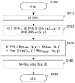
5A, 6A, 8A, 10A and 11A represent a flow chart of a method for encoding a picture block in a bitstream according to various embodiments;
5B, 6B, 8B, 10B and 11B show a flow chart of a method for decoding a picture block from a bitstream according to various embodiments;
FIG. 7 depicts the mapping function fmapAnd its inverse function invfmap;
FIG. 9 depicts the mapping function fmapDerivative f'mapAnd function 1/f'map(ii) a And
fig. 12 shows a full or limited range mapping function constructed from a dQP table.
Detailed description of the invention
It is to be understood that the figures and descriptions have been simplified to illustrate elements that are relevant for a clear understanding of the present principles, while eliminating, for purposes of clarity, many other elements found in typical encoding and/or decoding devices. It will be understood that, although the terms first and second may be used herein to describe various elements, these elements should not be limited by these terms. These terms are only used to distinguish one element from another.
The picture is an array of luma samples in monochrome format, or 4: 2: 0. 4: 2: 2 and 4: 4: an array of luma samples and two corresponding arrays of chroma samples in a 4-color format. Typically, a "block" is for a particular region in a sample array (e.g., luma Y), and a "unit" includes co-located blocks of all color components (luma Y and possibly chroma Cb and chroma Cr). A slice is an integer number of basic coding units, such as HEVC coding tree units or h.264 macroblock units. A stripe may comprise a complete picture and a portion thereof. Each slice may include one or more slice segments.
Hereinafter, the words "reconstructed" and "decoded" may be used interchangeably. Usually, but not necessarily, "reconstructed" is used at the encoder side and "decoded" at the decoder side. It should be noted that the term "decoded" or "reconstructed" may mean that the bitstream is partially "decoded" or "reconstructed", e.g., a signal obtained after deblocking filtering but before SAO filtering, and that the reconstructed samples may be different from the final decoded output for display. The terms "image", "picture" and "frame" may also be used interchangeably. The terms "sample" and "pixel" may also be used interchangeably.
Various embodiments are described with respect to the HEVC standard. However, the present principles are not limited to HEVC and may be applied to other standards, recommendations and extensions thereof, including, for example, HEVC or HEVC extensions, like format range (RExt), Scalability (SHVC), multiview (MV-HEVC) extensions and h.266. Various embodiments are described with respect to encoding/decoding of slices. They can be applied to encode/decode an entire picture or an entire picture sequence.
Reference to "one embodiment" or "an embodiment," as well as other variations of the present principles, means that a particular feature, structure, characteristic, etc. described in connection with the embodiment is included in at least one embodiment. Thus, the appearances of the phrase "in one embodiment" or "in an embodiment" or "in one implementation" or "in an implementation," as well any other variations, appearing in various places throughout the specification are not necessarily all referring to the same embodiment.
It is to be appreciated that the use of any of the following "/", "and/or" and "at least one of a or B", for example in the case of "a/B", "a and/or B" and "at least one of a or B", is intended to encompass the selection of only the first listed option (a), or only the second listed option (B), or both options (a and B). As another example, in the case of "a, B and/or C" and "at least one of a, B or C", such wording is intended to include selecting only the first listed option (a), or only the second listed option (B), or only the third listed option (C), or only the first and second listed options (a and B), or only the first and third listed options (a and C), or only the second and third listed options (B and C), or all three options (a and B and C). This can be extended for many of the items listed, as will be apparent to those of ordinary skill in this and related arts.
Various methods are described above, and each method includes one or more steps or actions for implementing the described method. The order and/or use of specific steps and/or actions may be modified or combined unless the proper operation of the method requires a specific order of steps or actions.
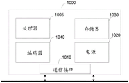
Fig. 1 represents an exemplary architecture of a transmitter 1000 configured to encode pictures in a bitstream, according to a specific and non-limiting embodiment.
Transmitter 1000 includes one or more processors 1005, which may include, for example, a CPU, GPU, and/or DSP (english acronym for digital signal processor), and internal memory 1030 (e.g., RAM, ROM, and/or EPROM). The transmitter 1000 includes one or more communication interfaces 1010 (e.g., keyboard, mouse, touchpad, webcam), each adapted to display output information and/or allow a user to input commands and/or data; and a power supply 1020, which may be external to transmitter 1000. The transmitter 1000 may also include one or more network interfaces (not shown). Encoder module 1040 represents a module that may be included in a device to perform encoding functions. In addition, the encoder module 1040 may be implemented as a separate element of the transmitter 1000, or may be incorporated into the processor 1005 as a combination of hardware and software, as known to those skilled in the art.
The pictures may be obtained from a source. According to various embodiments, the source may be, but is not limited to:
local memory, e.g. video memory, RAM, flash memory, hard disk;
a storage interface, for example an interface to a mass storage, ROM, optical disc or magnetic carrier;
a communication interface, for example a wired interface (e.g. a bus interface, a wide area network interface, a local area network interface) or a wireless interface (e.g. an IEEE 802.11 interface or a bluetooth interface); and
an image capturing circuit (e.g. a sensor such as e.g. a CCD (charge coupled device) or a CMOS (complementary metal oxide semiconductor)).
According to various embodiments, the bitstream may be transmitted to a destination. As an example, the bitstream is stored in a remote or local memory, e.g. video memory or RAM, hard disk. In a variant, the bitstream is sent to a storage interface, e.g. an interface to a mass storage, ROM, flash memory, optical disc or magnetic carrier, and/or transmitted over a communication interface (e.g. a point-to-point link, a communication bus, a point-to-multipoint link or an interface of a broadcast network).
According to an exemplary and non-limiting embodiment, the transmitter 1000 further comprises a computer program stored in the memory 1030. The computer program comprises instructions which, when executed by the transmitter 1000, in particular by the processor 1005, enable the transmitter 1000 to carry out the encoding method described with reference to fig. 5A, 6A, 8A, 10A and 11A. According to a variant, the computer program is stored outside the transmitter 1000 on a non-transitory digital data carrier (e.g. on an external storage medium such as a HDD, CD-ROM, DVD, read-only and/or DVD drive and/or DVD read/write drive, etc., all known in the art). The transmitter 1000 thus comprises a mechanism for reading a computer program. In addition, transmitter 1000 may access one or more Universal Serial Bus (USB) type storage devices (e.g., "memory sticks") through corresponding USB ports (not shown).
According to an exemplary and non-limiting embodiment, transmitter 1000 may be, but is not limited to:
-a mobile device;
-a communication device;
-a gaming device;
-a tablet (or tablet);
-a laptop computer;
-a still picture camera;
-a camera;
-a coding chip or coding device/means;
-a still picture server; and
a video server (e.g. a broadcast server, a video-on-demand server or a web server).
Fig. 2 illustrates an exemplary video encoder 100, such as an HEVC video encoder, adapted to perform an encoding method according to one of the embodiments of fig. 5A, 6A, 8A, 10A and 11A. The encoder 100 is an example of a transmitter 1000 or a part of the transmitter 1000.
For coding, a picture is typically divided into basic coding units, e.g., Coding Tree Units (CTUs) in HEVC or macroblock units in h.264. A group of possibly consecutive elementary coding units is grouped into stripes. The basic coding unit contains basic coding blocks for all color components. In HEVC, the smallest CTB size 16x16 corresponds to the macroblock size used in previous video coding standards. It will be understood that although the terms CTU and CTB are used herein to describe encoding/decoding methods and encoding/decoding devices, these methods and devices should not be limited by these particular terms, which may be expressed differently (e.g., macroblocks) in other standards, such as h.264.
In HEVC, a CTB is the root of a quadtree partition into Coding Blocks (CB), which are partitioned into one or more Prediction Blocks (PB), and form the root of a quadtree partition into Transform Blocks (TB). Corresponding to the coding block, the prediction block, and the transform block, the Coding Unit (CU) includes a Prediction Unit (PU) including prediction information of all color components and a tree-structured Transform Unit (TU) group, and the TU includes a residual coding syntax structure of each color component. The sizes of CB, PB, and TB of the luminance components are suitable for the respective CUs, PU, and TU. In this application, the term "block" or "picture block" may be used to refer to any one of CTU, CU, PU, TU, CB, PB, and TB. In addition, the term "block" or "picture block" may be used to refer to macroblocks, partitions, and sub-blocks specified in the h.264/AVC or other video coding standard, and more generally to sample arrays of various sizes.
In the exemplary encoder 100, the pictures are encoded by the encoder elements as described below. The picture to be encoded is processed in units of CUs. Each CU is encoded using intra or inter modes. When a CU is encoded in intra mode, it performs intra prediction (160). In inter mode, motion estimation (175) and compensation (170) are performed. The encoder determines (105) which of an intra mode or an inter mode to use for encoding the CU, and indicates an intra/inter decision by a prediction mode flag. The residual is calculated by subtracting (110) the predicted block of samples (also called predictor) from the original picture block. The prediction sample block comprises a prediction value, one for each sample of the block.
A CU in intra mode is predicted from reconstructed neighboring samples within the same slice. A group of 35 intra prediction modes are available in HEVC, including DC, planar and 33 angular prediction modes. The intra-prediction reference is reconstructed from rows and columns adjacent to the current block. Using available samples from a previously reconstructed block, the reference extends in the horizontal and vertical directions over twice the block size. When the angular prediction mode is used for intra prediction, the reference samples may be copied in the direction indicated by the angular prediction mode.
The applicable luma intra prediction mode for the current block may be encoded using two different options. If the applicable mode is included in the constructed list of three Most Probable Modes (MPMs), then that mode is signaled by an index in the MPM list. Otherwise, the mode is signaled by a fixed length binarization of the mode index. The three most probable modes are derived from the intra prediction modes of the top and left neighboring blocks.
For inter-CUs, the respective coding block is further divided into one or more prediction blocks. Inter prediction is performed at the PB level, and the corresponding PU contains information on how to perform inter prediction. The motion information (i.e., motion vector and reference index) can be signaled in two ways, namely "Advanced Motion Vector Prediction (AMVP)" and "merge mode". In AMVP, a video encoder or decoder assembles a candidate list based on motion vectors determined from encoded blocks. The video encoder then signals an index into the candidate list to identify a Motion Vector Predictor (MVP) and signals a Motion Vector Difference (MVD). At the decoder side, the Motion Vectors (MVs) are reconstructed as MVP + MVDs.
In merge mode, the video encoder or decoder assembles a candidate list based on already encoded blocks, and the video encoder signals an index of one of the candidates in the candidate list. At the decoder side, the motion vectors and reference picture indices are reconstructed based on the signaled candidates.
In HEVC, the precision of motion information for motion compensation is one-quarter sample for the luma component and one-eighth sample for the chroma component. A 7-tap or 8-tap interpolation filter is used to interpolate fractional sample positions, i.e. 1/4, 1/2 and 3/4 for the full sample position of the luminance in the horizontal and vertical directions can be addressed.
The residual is transformed (125) and quantized (130). The quantized transform coefficients are entropy encoded (145) along with motion vectors and other syntax elements to output a bitstream. The encoder may also skip the transform and apply quantization directly to the untransformed residual signal on a 4x4 TU basis. The encoder may also bypass both transform and quantization, i.e. directly encode the residual without applying a transform or quantization process. In direct PCM coding, no prediction is applied and the coded unit samples are directly coded into the bitstream.
The encoder includes a decoding loop and therefore decodes the encoded block to provide a reference for further prediction. The quantized transform coefficients are dequantized (140) and inverse transformed (150) to decode the residual. The picture block is reconstructed by combining (155) the decoded residual and the predicted sample block. An in-loop filter (165) is applied to the reconstructed picture, for example to perform deblocking/SAO (sample adaptive offset) filtering to reduce coding artifacts. The filtered pictures may be stored in a reference picture buffer (180) and used as references for other pictures.
In HEVC, SAO filtering may be activated or deactivated at the video level, slice level, and CTB level. Two SAO modes are specified: edge Offset (EO) and Band Offset (BO). For EO, the sample classification is based on the local directional structure in the picture to be filtered. For BO, the sample classification is based on the sample value. Parameters for EO or BO may be explicitly coded or derived from the neighborhood. SAO may be applied to luma and chroma components, where the SAO mode is the same for Cb and Cr components. SAO parameters (i.e., offset, SAO type EO, BO and disable, category at EO and band location at BO) are configured separately for each color component.
Fig. 3 represents an exemplary architecture of a receiver 2000 configured to decode pictures from a bitstream to obtain decoded pictures, according to a specific and non-limiting embodiment.
Receiver 2000 includes one or more processors 2005, which may include, for example, a CPU, GPU, and/or DSP (english acronym for digital signal processor), and internal memory 2030 (e.g., RAM, ROM, and/or EPROM). Receiver 2000 includes one or more communication interfaces 2010 (e.g., keyboard, mouse, touchpad, webcam), each adapted to display output information and/or allow a user to input commands and/or data; and power supply 2020, may be located external to receiver 2000. Receiver 2000 may also include one or more network interfaces (not shown). Decoder module 2040 represents a module that may be included in a device to perform decoding functions. In addition, the decoder module 2040 may be implemented as a separate element of the receiver 2000, or may be incorporated into the processor 2005 as a combination of hardware and software, as known to those skilled in the art.
The bitstream may be obtained from a source. According to various embodiments, the source may be, but is not limited to:
local memory, e.g. video memory, RAM, flash memory, hard disk;
a storage interface, for example an interface to a mass storage, ROM, optical disc or magnetic carrier;
a communication interface, for example a wired interface (e.g. a bus interface, a wide area network interface, a local area network interface) or a wireless interface (such as an IEEE 802.11 interface or a bluetooth interface); and
an image capturing circuit (e.g. a sensor such as e.g. a CCD (charge coupled device) or a CMOS (complementary metal oxide semiconductor)).
According to various embodiments, the decoded pictures may be sent to a destination, e.g., a display device. As an example, the decoded pictures are stored in a remote or local memory, e.g. video memory or RAM, hard disk. In a variant, the decoded pictures are sent to a storage interface, e.g. an interface with a mass storage, ROM, flash memory, optical disc or magnetic carrier and/or transmitted over a communication interface (e.g. a point-to-point link, a communication bus, a point-to-multipoint link or an interface of a broadcast network).
According to a specific and non-limiting embodiment, the receiver 2000 also includes a computer program stored in the memory 2030. The computer program comprises instructions which, when executed by the receiver 2000, in particular by the processor 2005, enable the receiver to perform the decoding method described with reference to fig. 5B, 6B, 8B, 10B and 11B. According to a variant, the computer program is stored outside the receiver 2000 on a non-transitory digital data carrier (e.g. on an external storage medium, such as a HDD, CD-ROM, DVD, read-only and/or DVD drive and/or DVD read/write drive, all known in the art). The receiver 2000 thus comprises a mechanism for reading the computer program. In addition, receiver 2000 may access one or more Universal Serial Bus (USB) type storage devices (e.g., "memory sticks") through corresponding USB ports (not shown).
According to an exemplary and non-limiting embodiment, the receiver 2000 may be, but is not limited to:
-a mobile device;
-a communication device;
-a gaming device;
-a set-top box;
-a television set;
-a tablet (tablet computer);
-a laptop computer;
-video players, e.g. blu-ray players, DVD players;
-a display; and
-a decoding chip or decoding device/means.
Fig. 4 illustrates a block diagram of an exemplary video decoder 200 (e.g., an HEVC video decoder) adapted to perform a decoding method according to the embodiments of fig. 5B, 6B, 8B, 10B and 11B. The video decoder 200 is an example of a receiver 2000 or a part of such a receiver 2000. In the exemplary decoder 200, the bitstream is decoded by decoder elements as described below. Video decoder 200 generally performs the inverse of the decoding channel described in fig. 2, which performs video decoding as part of the encoded video data.
In particular, the input to the decoder comprises a video bitstream that can be generated by the video encoder 100. The bitstream is first entropy decoded (230) to obtain transform coefficients, motion vectors and other coding information. The transform coefficients are de-quantized (240) and inverse transformed (250) to decode the residual. The decoded residual is then combined (255) with the predicted block of samples (also referred to as predictor) to obtain a decoded/reconstructed picture block. The predicted block of samples may be obtained (270) from intra prediction (260) or motion compensated prediction (i.e., inter prediction) (275). As described above, AMVP and merge mode techniques may be used during motion compensation, which may use an interpolation filter to calculate interpolated values for sub-integer samples of a reference block. An in-loop filter (265) is applied to the reconstructed picture. The in-loop filter may include a deblocking filter and an SAO filter. The filtered picture is stored in a reference picture buffer (280).
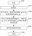
Fig. 5A shows a flow diagram of a method for encoding a picture block in a bitstream in accordance with the present principles. The mapping is applied in a coding loop to obtain mapped residual samples at the pixel level. In contrast to the prior art, the input samples of the encoding method are not modified by the mapping. On the decoder side, the output samples from the decoder are not modified by the inverse mapping.
The mapping may be applied to one or several components of the picture. For example, it may be applied to only the luminance component, or only the chrominance component, or both the luminance and chrominance components.
The method starts in step S100. In step S110, the transmitter 1000 (e.g., such as the encoder 100) accesses a block of a picture slice. In step S120, the sender obtains a predicted value Pred (x, y) of its source value Orig (x, y) for at least one sample of the accessed block and for at least one component (e.g. for luminance), where (x, y) is the spatial coordinates of the samples in the picture. A prediction value is obtained, i.e. usually determined, depending on the prediction mode (intra/inter mode) selected for the block.
In step S130, the sender responds to the mapping function fmap() The mapped residual values of the samples are determined from the source values Orig (x, y) and the prediction values Pred (x, y) of the samples. The mapping function is defined or derived to obtain coding gain, i.e. to reduce the bit cost, i.e. the number of bits, of the bitstream for a given visual or objective quality of reconstruction, or to increase the visual or objective quality of reconstruction for a given bit cost. When a block, picture or sequence of pictures is encoded in a bitstream of a given size (i.e. a given number of bits), the quality of the reconstruction at the receiver of the block, picture or sequence of pictures depends on the size. On the other hand, when a sequence of blocks, pictures is coded with a given reconstructed quality, then the size of the bitstream depends on this reconstructed quality.
In most cases, the distortion, which represents the quality of the reconstruction, is defined as the expectation of the square of the difference between the input and output signals (i.e., the mean square error). However, since most lossy compression techniques operate on data (viewing pictures and video) that is to be perceived by human consumers, the distortion measure may preferably be modeled based on human perception and perhaps aesthetics.
For example, the mapping function may be derived by one of the following methods:
-deriving the mapping function such that the magnitude of the residual values increases more for large magnitude values of the component values than for small magnitude values of the component values, as shown in fig. 7;
a predefined encoder quantization adjustment table deltaQP or quantization adjustment function dqp (Y) may be derived or tuned, where Y is the video signal luminance, to obtain improved perceptual or objective coding performance. From deltaQP or dqp (y), the scaling function can be derived as follows: sc (Y) < 2^ (-dQP (Y)/6), where ^ is the power operator. A scaling function may be used in the mapping function, which will correspond to the product of the residual and the scaling value derived from the scaling function. In a variant, the mapping function may be derived by considering that the scaling function is a derivative function of the mapping function applied to the residual.
In step S130, the precoder function map (y) or the derivative of map (y) as scaling function may be used as the mapping function fmap() To map residual values, where Y is the luminance video signal. The precoder function map (y) is derived such that the original samples of the signal, once mapped by this precoder function map (y), can be better distributed over the entire codeword (e.g. due to histogram equalization).
In addition to the three methods mentioned above, if the mapping residual values improve compression performance, other methods may be used to derive the mapping function.
Steps S110 and S120 may be repeated for each sample of the accessed block to obtain a block of mapped residual values.
The transmitter encodes the mapped residual values at step S140. Encoding the mapped residual values typically, but not necessarily, comprises transforming the residual into transform coefficients, quantizing the coefficients with a quantization step QP to obtain quantized coefficients, and entropy encoding the quantized coefficients in a bitstream.
The method ends at step S180.
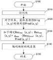
Fig. 5B shows a flowchart of a method for decoding a picture block in a bitstream corresponding to the encoding method of fig. 5A.
The method starts in step S200. In step S210, the receiver 2000, such as the decoder 200, accesses the bitstream.
In step S220, the receiver obtains a prediction value Pred (x, y) for at least one sample for at least one component (e.g., for luminance), where (x, y) is the spatial coordinates of the sample in the picture. A prediction value is obtained according to the prediction mode (intra/inter mode) selected for the block.
In step S230, the receiver decodes the residual values Res (x, y) of the samples to be decoded. The residual values Res (x, y) are decoded versions of the mapped residual values encoded at step S140 of fig. 5A. Decoding typically, but not necessarily, includes entropy decoding a portion of a bitstream representing a block to obtain a block of transform coefficients, to dequantize and inverse transform the block of transform coefficients to obtain a block of residuals.
In step S240, the sender responds to the mapping function invfmap() Determining reconstructed sample values for the samples from the decoded residual values and the prediction values, mapping the function invfmap() Is the mapping function f used by the encoding method in step 130map() The inverse of (c). Steps S220 to S240 may be repeated for each sample of the accessed block.
The method ends at step S280.
Fig. 6A shows a flow chart of a method for encoding a picture block in a bitstream according to a first specific and non-limiting embodiment.
The method starts in step S100. In step S110, the transmitter 1000, such as the encoder 100 for example, accesses a block of a picture slice. In step S120, the transmitter obtains, for at least one component (e.g., for luminance), a predicted value Pred (x, y) of the value Orig (x, y) of at least one sample of the accessed block, where (x, y) is the spatial coordinates of the samples in the picture. A prediction value is obtained according to the prediction mode (intra/inter mode) selected for the block.
In step S130, the sender responds to the mapping function fmap() The mapped residual values of the samples are determined from the source values Orig (x, y) and the prediction values Pred (x, y) of the samples. The mapping function is defined or derived to obtain a coding gain, i.e. to decrease the bit rate for a given visual or objective quality, or to increase the visual or objective quality for a given bit rate. The mapping function may be derived by one of the methods disclosed with reference to fig. 5A. Steps S110 to S130 may be repeated for each sample of the accessed block to obtain a block of mapped residual values. In the first embodiment, denoted as ResmapThe mapping residual of (x, y) is equal to fmap(Orig(x,y))–fmap(Pred(x,y))。
The transmitter encodes the mapped residual values at step S140. Encoding the mapped residual values typically, but not necessarily, comprises transforming the residual into transform coefficients, quantizing the coefficients with a quantization step QP to obtain quantized coefficients, and entropy encoding the quantized coefficients in a bitstream.
The method ends at step S180.
Fig. 6B shows a flow chart of a method for decoding a picture block in a bitstream corresponding to an embodiment of the coding method according to fig. 6A, according to a first specific and non-limiting embodiment.
The method starts in step S200. In step S210, the receiver 2000, such as the decoder 200, accesses the bitstream.
In step S220, the receiver obtains a prediction value Pred (x, y) for at least one sample for at least one component (e.g., for luminance), where (x, y) is the spatial coordinates of the sample in the picture. A prediction value is obtained according to the prediction mode (intra/inter mode) selected for the block.
In step S230, the receiver decodes the residual values Res (x, y) of the samples to be decoded. The residual values Res (x, y) are decoded versions of the mapped residual values encoded at step S140 of fig. 6A. Decoding typically, but not necessarily, includes entropy decoding a portion of a bitstream representing a block to obtain a block of transform coefficients, de-quantizing and inverse transforming the block of transform coefficients to obtain a block of residuals.
In step S240, the transmitter responds to the mapping function f used by the encoding method in step S130map() And its inverse invfmap() A reconstructed sample value Dec (x, y) is determined for a sample from the decoded residual value Res (x, y) and the prediction value Pred (x, y). Steps S220 to S240 may be repeated for each sample of the accessed block to obtain a reconstructed block. In a first embodiment, the reconstructed sample value denoted Dec (x, y) is equal to invfmap(Res(x,y)+fmap(Pred(x,y)))。
The method ends at step S280.
Fig. 8A shows a flow chart of a method for encoding a picture block in a bitstream according to a second specific and non-limiting embodiment.
The method starts in step S100. In step S110, the transmitter 1000, such as the encoder 100, for example, accesses a block of a picture slice. In step S120, the transmitter obtains, for at least one component (e.g., for luminance), a predicted value Pred (x, y) of the value Orig (x, y) of at least one sample of the accessed block, where (x, y) is the spatial coordinates of the samples in the picture. A prediction value is obtained according to the prediction mode (intra/inter mode) selected for the block.
In step S130, the sender responds to the mapping function gmap() The mapped residual values of the samples are determined from the source values Orig (x, y) and the prediction values Pred (x, y) of the samples. The mapping function is defined or derived to obtain coding gain, i.e. to decrease the bit rate for a given visual or objective quality, or to increase the visual or objective quality for a given bit rate. The mapping function may be derived by one of the methods disclosed with reference to fig. 5A. Steps S110 to S130 may be repeated for each sample of the accessed block to obtain a block of mapped residual values. In a second embodiment, denoted as ResmapThe residual of the mapping of (x, y) is equal to gmap(Resusual(x, y), Pred (x, y)), where Resusual(x,y)=Orig(x,y)–Pred(x,y)。
The function g can be derived from the first embodimentmap(p, v) and invgmapA simple version of (p, v). For the prediction value p and the sample residual value v, g can be constructed as followsmap(p, v) and invgmap(p,v)。
In a first embodiment, Resremap(x,y)=fmap(Orig(x,y))–fmap(Pred(x,y))。
If the signals Orig (x, y) and Pred (x, y) are close, which can be expected when the prediction is good, then Orig (x, y) can be considered to be Pred (x, y) + e, e being a very small amplitude. Considering the definition of the derivative of the function, it can be considered that
fmap(Orig(x,y))=fmap(Pred(x,y)+e)≈fmap(Pred(x,y))+e*f’map(Pred(x,y))
Wherein f ismapCorresponds to a 1D function, e.g. as defined in example 1, and f'mapIs a function fmapThe derivative of (c).
Then Resmap(x,y)=fmap(Orig(x,y))–fmap(Pred(x,y))≈e*f’map(Pred(x,y))。
By definition, e-origin (x, y) -Pred (x, y) is the usual prediction residual Resusual(x,y)。
Therefore, we can use the following function gmap(p, v) and invgmap(p,v):
gmap(p,v)=f’map(p)*v
invgmap(p,v)=(1/f’map(p))*v
At the encoder, the mapped residuals are derived as follows:
Resmap(x,y)=f’map(Pred(x,y))*Resusual(x, y) (Eq. 1)
At the decoder, the reconstructed signal is derived as follows:
Dec(x,y)=Pred(x,y)+1/f’map(Pred(x,y))*Resdec(x, y)) (equation 2)
This means that the mapping is a simple scaling of the ordinary residual by a scale factor that depends on the predictor. Possibly at the encoder, the scaling factor depends on the original value and not on the predicted value. However, by doing so, a mismatch between the encoder and the decoder is generated. By using a smoothing filter, a filtered version of the prediction may also be used, e.g. to reduce the effect of quantization errors.
For example, instead of using Pred (x, y) in equations 1 and 2, a filtered version (Pred (x-1, y)/4+ Pred (x, y)/2+ Pred (x +1, y))/4) may be used.
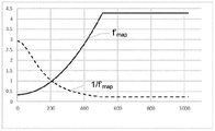
FIG. 9 gives examples of the functions f 'map and (1/f' map).
The transmitter encodes the mapped residual values at step S140. Encoding the mapped residual values typically, but not necessarily, comprises transforming the residual into transform coefficients, quantizing the coefficients with a quantization step QP to obtain quantized coefficients, and entropy encoding the quantized coefficients in a bitstream.
The method ends at step S180.
Fig. 8B shows a flow chart of a method for decoding a picture block in a bitstream corresponding to the encoding method disclosed with respect to fig. 8A.
The method starts in step S200. In step S210, the receiver 2000, such as the decoder 200, accesses the bitstream.
In step S220, the receiver obtains a prediction value Pred (x, y) for at least one sample for at least one component (e.g., for luminance), where (x, y) is a spatial coordinate of the picture in space. The prediction value is obtained depending on the prediction mode (intra/inter mode) selected for the block.
In step S230, the receiver decodes residual values Res (x, y) of samples to be decoded. The residual values Res (x, y) are decoded versions of the mapped residual values encoded at step S140 of fig. 8A. Decoding typically, but not necessarily, includes entropy decoding a portion of a bitstream representing a block to obtain a block of transform coefficients, de-quantizing and inverse transforming the block of transform coefficients to obtain a block of residuals.
In step S240, the sender responds to the mapping function invgmapDetermining reconstructed sample values Dec (x, y), mapping function invg, for a sample from decoded residual values Res (x, y) and predicted values Pred (x, y)mapIs the mapping function g used in the encoding method of step S130 in fig. 8Amap() The inverse of (c). Steps S220 to S240 may be repeated for each sample of the accessed block to obtain a reconstructed block. In a second embodiment, the reconstructed sample value denoted Dec (x, y) is equal to Pred (x, y) + invgmap(Res(x,y),Pred(x,y))。
This embodiment advantageously allows using invg at the decodermapThe function maps the prediction residual in a single step, whereas the first embodiment requires the simultaneous application of fmapFunction sum invfmap。
The method ends at step S280.
Fig. 10A shows a flow chart of a method for encoding a picture block in a bitstream according to a third specific and non-limiting embodiment. This embodiment is a generalization of the second embodiment. Function fmapAnd invfmap() Is a scaling function whose scaling factor depends on the value of the prediction signal (or, as mentioned before, a filtered version of the prediction signal).
The method starts in step S100. In step S110, the transmitter 1000, such as the encoder 100, accesses a block of a picture slice. In step S120, the transmitter obtains, for at least one component (e.g., for luminance), a predicted value Pred (x, y) of the value Orig (x, y) of at least one sample of the accessed block, where (x, y) is the spatial coordinates of the samples in the picture. The prediction value is obtained depending on the prediction mode (intra/inter mode) selected for the block.
In step S130, the sender responds to the mapping function fmap() The mapped residual values of the samples are determined from the source values Orig (x, y) and the prediction values Pred (x, y) of the samples. The mapping function is defined or derived to obtain coding gain, i.e., to reduce the bit rate for a given visual or objective quality, or to improve the visual or objective quality for a given bit rate. The mapping function may be derived by one of the methods disclosed with reference to fig. 5A. Steps S110 to S130 may be repeated for each sample of the accessed block to obtain a block of mapped residual values. In a second embodiment, denoted as ResmapThe residual of the mapping of (x, y) is equal to fmap(Pred(x,y))*Resusual(x, y) where Resusual(x, y) -origin (x, y) -Pred (x, y). This is a generalized version of (equation 1) and (equation 2). In a variant, the original value Orig (x, y) can be used instead of Pred (x, y). In this case, Resmap(x, y) is equal to fmap(Orig(x,y))*Resusual(x, y). In another variant, a combination Comb (x, y) of Orig (x, y) and Pred (x, y) may be used, for example the average of these two values. In the latter case, Resmap(x, y) is equal to fmap(Comb(x,y))*Resusual(x,y)。
The transmitter encodes the mapped residual values at step S140. Encoding the mapped residual values typically, but not necessarily, comprises transforming the residual into transform coefficients, quantizing the coefficients with a quantization step QP to obtain quantized coefficients, and entropy encoding the quantized coefficients in a bitstream.
The method ends at step S180.
Fig. 10B represents a flow chart of a method for decoding a picture block from a bitstream corresponding to the encoding method disclosed with respect to fig. 10A.
The method starts in step S200. In step S210, the receiver 2000, such as the decoder 200, accesses the bitstream.
In step S220, the receiver obtains a prediction value Pred (x, y) for at least one sample for at least one component (e.g., for luminance), where (x, y) is the spatial coordinates of the sample in the picture. The prediction value is obtained depending on the prediction mode (intra/inter mode) selected for the block.
In step S230, the receiver decodes the residual values Res (x, y) of the samples to be decoded. The residual values Res (x, y) are decoded versions of the mapped residual values encoded in step S140 of fig. 10A. Decoding typically, but not necessarily, includes entropy decoding a portion of a bitstream representing a block to obtain a block of transform coefficients, de-quantizing and inverse transforming the block of transform coefficients to obtain a block of residuals.
In step S240, the receiver responds to the mapping function invf used by the encoding method in step S130map()=1/fmap() A reconstructed sample value Dec (x, y) is determined for a sample from the decoded residual value Res (x, y) and the prediction value Pred (x, y). Steps S220 to S240 may be repeated for each sample of the accessed block to obtain a reconstructed block. In a second embodiment, the reconstructed sample value denoted Dec (x, y) is equal to Pred (x, y) + (1/f)map(Pred(x,y)))*Res(x,y)。
This embodiment advantageously allows performing inverse mapping at the decoder by using simple multiplication, which brings limited added complexity and enables performing accurate mapping, where rounding operations can be done at the end of the processing (when computing Dec (x, y)).
The method ends at step S280.
Fig. 11A shows a flow chart of a method for encoding a picture block in a bitstream according to a fourth specific and non-limiting embodiment. In this embodiment, the mapping is a cross-component scaling. For example, the mapping depends on the co-located luma component Y (or a filtered version thereof) being applied to chroma components C, C being either U (or Cb) or V (or Cr). When the resolutions of the luma and chroma pictures are different (e.g., for a 4: 2: 0 chroma format), the luma value may be taken after resampling or as one of the sample values of the luma picture associated with the chroma samples. For example, in 4: 2: in the case of the 0 signal, the luminance value of the position (2 × x, 2 × y) can be considered for the position (x, y) in the screen.
The method starts in step S100. In step S110, the transmitter 1000, such as the encoder 100, for example, accesses a block of a picture slice. In step S120, the sender obtains, for at least one component (e.g., for chroma C), a prediction value PredC (x, Y) of the source value OrigC (x, Y) for at least one sample of the accessed block, where (x, Y) is the spatial coordinates of the sample in the picture, and further obtains, for at least another component (e.g., luma Y), a prediction value PredY (x, Y) of the source value OrigY (x, Y) for the same sample. The prediction value is obtained depending on the prediction mode (intra/inter mode) selected for the block.
In step S130, the sender responds to the mapping function fmap() The mapped residual values of the sample are determined from the source value OrigC (x, y) of the sample and the predicted values PredC (x, y) and PredY (x, y). The mapping function is defined or derived to obtain coding gain, i.e., to reduce the bit rate for a given visual or objective quality, or to improve the visual or objective quality for a given bit rate. The mapping function may be derived by one of the methods disclosed with reference to fig. 5A. Steps S110 to S130 may be repeated for each sample of the accessed block to obtain a block of mapped residual values. In the fourth embodiment, denoted as ResCmapThe mapping residual of (x, y) is equal to fmap(PredY(x,y))*ResCusual(x, y), wherein ResCusual(x, y) -origin (x, y) -PredC (x, y), where origin (x, y) is the value of the source sample of chroma component C (to be encoded) at position (x, y) in the picture, PredC (x, y) is the value of the prediction sample of chroma component C, and ResCusual(x, y) is the value of the prediction residual sample of the chrominance component C.
The transmitter encodes the mapped residual values at step S140. Encoding the mapped residual values typically, but not necessarily, includes transforming the residual into transform coefficients, quantizing the coefficients with a quantization step size QP to obtain quantized coefficients, and entropy encoding the quantized coefficients in a bitstream.
The method ends at step S180.
Fig. 11B shows a flow chart of a method for decoding a picture block from a bitstream corresponding to the encoding method disclosed in relation to fig. 11A.
The method starts in step S200. In step S210, the receiver 2000, such as the decoder 200, accesses the bitstream.
In step S220, the receiver obtains, for at least one component (e.g., for chroma C), a predicted value PredC (x, Y) of the source value OrigC (x, Y) for at least one sample of the accessed block, where (x, Y) is the spatial coordinates of the samples in the picture, and further obtains, for at least another component (e.g., luma Y), a predicted value PredY (x, Y) of the source value OrigY (x, Y) for the same sample (possibly with downsampling when the resolutions of luma and chroma pictures are different). The prediction value is obtained depending on the prediction mode (intra/inter mode) selected for the block.
In step S230, the receiver decodes residual values ResC (x, y) of samples to be decoded. The residual values ResC (x, y) are decoded versions of the mapped residual values encoded at step S140 of fig. 11A. Decoding typically, but not necessarily, includes entropy decoding a portion of a bitstream representing a block to obtain a block of transform coefficients, de-quantizing and inverse transforming the block of transform coefficients to obtain a block of residuals.
In step S240, the receiver responds to the mapping function 1/fmap() For a sample, a reconstructed sample value DecC (x, y) is determined from the decoded residual value ResC (x, y) and the prediction values PredC (x, y) and PredY (x, y), where fmap() Is the mapping function used by the encoding method at step S130. Steps S220 to S240 may be repeated for each sample of the accessed block to obtain a reconstructed chroma block. In a fourth embodiment, the reconstructed sample value denoted DecC (x, y) is equal to PredC (x, y) + (1/f)map(PredY(x,y)))*ResC(x,y)。
This embodiment advantageously allows the chroma component to be scaled at the decoder depending on the luma component, typically resulting in an improved visual quality due to a fine control of the chroma scaling for different luma intervals.
The method ends at step S280.
The third and fourth embodiments disclosed in relation to fig. 10A, 10B, 11A and 11B may advantageously be implemented in a fixed point manner.
Make ResCusualIs the prediction residual at position (x, y), mapped with a scaling factor scal, e.g. in case of cross component scaling, from f at value PredYmapThe value (the co-located value used as the predicted luma for the cross component) is derived): scal ═ fmap (perdy).
Used at the decoder (and possibly encoded in the bitstream as will be explained below) is invScal round (2^ B ÷ scal).
H is a power operator,
round (x) is the closest integer value of x,
b is bitDepth (typically, B ═ 8 or 10 bits) selected to quantize the scaling factor
Value ResCusualTo the mapped value ResCmapThe mapping of (2) applies as follows:
ResCmap=(ResCusual*2B+sign(ResCusual) (invScal/2))/invScal (equation 3)
Wherein ResCusual(x, y) -OrigC (x, y) -PredC (x, y), and when x is greater than x>Sign (x) equals 1 when 0, otherwise-1.
All parameters in this equation are integers and the division "/" also applies to integers (whereas division/is floating-point division). Then to the mapping value ResCmapAnd (6) coding is carried out.
At the decoder side, the mapped values ResC to be encodedmapDecoding into the value ResCmap_dec. Decoded value ResCmap_decTo the reverse mapped value ResCinvmapThe inverse mapping of (c) applies as follows:
ResCinvmap=(ResCmap_dec*invScal+sign(ResCmap_dec)*2(B-1))/2B(equation 4)
(ResCmap_dec*invScal+sign(ResCmap_dec)*2(B-1))/2B
It is equivalent to:
ResCinvmap=(ResCmap_dec*invScal+sign(ResCmap_dec)*2(B-1))>>b (equation 5)
Then predict values PredC and ResC from location (x, y)invmapDeriving the reconstruction value DecC as DecC ═ PredC + ResCinvmap(equation 6)
These operations may also be combined directly to avoid the use of symbolic operators. Equations (equation 5) and (equation 6) are combined into (equation 7).
DecC=(PredC*2B+ResCmap_dec*invScal+2(B-1))>>B (equation 7).
In HEVC, quantization is tuned using a quantization parameter QP. From the QP, the quantization step Qstep0 is derived and can be approximated as (K x 2 (QP/6)), where K is a fixed parameter.
When using local QP to correct dQP, the actual quantization step Qstep1 can be approximated as (K x 2^ ((QP + dQP)/6)), i.e., (Qstep0 x 2^ (dQP/6)). The signal is divided by the quantization step.
This means that for a given dQP, the corresponding scaling of the signal derived from the inverse of the quantization step is applied in the quantization to 2^ (-dQP/6).
For example, the following correspondence may be established for the dQP table.


This scaling may be used, for example, in the scaling solution described in the third embodiment. The scaling may also be used to derive a mapping function as used in the first and second embodiments. In practice, the scaling corresponds to the derivative of the mapping function. Thus, the mapping function may be modeled as a piecewise linear function, where each segment has a slope equal to the scaling corresponding to that segment.
If d is to beQP table is defined as a set of intervals Yi,Yi+1–1]Where dQP value dQPiAssociated with each interval, for i-0 to n, n being an integer, the mapping function may be defined as follows.
Let i be the index of the interval containing Y (Y is in [ Y ]i,Yi+1–1]In (1).
fmap(Y)=fmap(Yi)+2^(–dQPi/6)*(Y-Yi)
For the particular dQP table above, this gives the function shown in fig. 12 for either Full Range (FR) or Limited Range (LR) signal representation.
Function fmapOr gmapOr its inverse function invfmapOr invgmapMay be defined explicitly in the decoder (and thus in the decoder specification) or signaled in the bitstream.
Function fmap,invfmap,gmapOr invgmapCan be realized in the following forms:
a look-up table is provided for,
a piecewise scalar function (PWS),
a piecewise linear function (PWL),
a piecewise polynomial function (PWP).
They may be coded in SEI messages, Sequence Parameter Sets (SPS), Picture Parameter Sets (PPS), slice headers, Coding Tree Unit (CTU) syntax, per tile, or new structures such as Adaptive Picture Set (APS).
The implementations described herein may be implemented, for example, in methods or processes, apparatus, software programs, data streams, or signals. Even if only discussed in the context of a single form of implementation (e.g., discussed only as a method or device), the implementation of the features discussed can be implemented in other forms (e.g., a program). An apparatus may be implemented in, for example, appropriate hardware, software and firmware. The method may be implemented in, for example, an apparatus such as a processor, which refers generally to a processing device including, for example, a computer, microprocessor, integrated circuit, or programmable logic device. Processors also include communication devices, such as, for example, computers, cellular telephones, portable/personal digital assistants ("PDAs"), and other devices that facilitate the communication of information between end-users.
Implementations of the various processes and features described herein may be embodied in a variety of different devices or applications, such as devices or applications, among others. Examples of such devices include encoders, decoders, post-processors that process output from decoders, pre-processors that provide input to encoders, video decoders, video codecs, Web servers, set-top boxes, laptops, personal computers, cell phones, PDAs, and other communication devices. It should be clear that the device may be mobile, even mounted in a moving vehicle.
Additionally, the methods may be implemented by instructions being executed by a processor, and such instructions (and/or data values produced by the implementation) may be stored on a processor-readable medium such as, for example, an integrated circuit, a software carrier or other storage device (such as, for example, a hard disk, a Compact Disc (CD), an optical disc (e.g., a DVD, commonly referred to as a digital versatile disc or a digital video disc), a random access memory ("RAM"), or a read only memory ("ROM")). The instructions may form an application program tangibly embodied on a processor-readable medium. The instructions may be, for example, hardware, firmware, software, or a combination thereof. The instructions may be found in, for example, an operating system, a separate application, or a combination of both. Thus, a processor may be characterized, for example, as a device configured to perform a process and a device (such as a storage device) including a processor-readable medium having instructions for implementing a process. Additionally, a processor-readable medium may store data values produced by an implementation in addition to or in place of instructions.
As will be apparent to those of skill in the art, implementations may produce various signals formatted to carry information that may be stored or transmitted, for example. The information may include, for example, instructions for performing a method or data generated by one of the described implementations. For example, a signal may be formatted to carry as data either the rules for writing or reading the syntax of the described embodiments, or the actual syntax values written by the described embodiments. Such signals may be formatted, for example, as electromagnetic waves (e.g., using the radio frequency portion of the spectrum) or as baseband signals. Formatting may include, for example, encoding a data stream and modulating a carrier with the encoded data stream. The information carried by the signal may be, for example, analog or digital information. The signal may be transmitted over a variety of different wired or wireless links, as is well known. The signal may be stored on a processor readable medium.
Many implementations have been described. Nevertheless, it will be understood that various modifications may be made. For example, elements of different implementations may be combined, supplemented, modified or removed to produce other implementations. In addition, those of ordinary skill in the art will appreciate that other structures and processes may be substituted for those disclosed and that the resulting implementations will perform at least substantially the same function(s) in at least substantially the same way to achieve at least substantially the same result(s) as the disclosed implementations. Accordingly, this application contemplates these and other implementations.
Claims (8)
1. A method for encoding, comprising:
-obtaining a prediction value of a source value of a current color component of a sample of a block of a picture;
-determining mapped residual values from source values and from predicted values of the current color component using a mapping function; and
-encoding the mapped residual values into a bitstream;
wherein determining the mapped residual values comprises:
-mapping the predicted value using a mapping function to obtain a mapped predicted value;
-mapping the source values using a mapping function to obtain mapped source values; and
-determining a mapped residual value representing a subtraction of a mapped prediction value from a mapped source value.
2. A method for decoding, comprising:
-obtaining a prediction value of a current color component of a sample of a block of a picture;
-decoding residual values of the samples; and
-determining reconstructed values of the samples from the decoded residual values and from the predicted values using the mapping function and an inverse mapping function being the inverse of the mapping function;
wherein determining the reconstruction value comprises:
-mapping the predicted value using a mapping function to obtain a mapped predicted value;
-obtaining an intermediate value representing the sum of the mapped prediction value and the residual value; and
-obtaining a reconstructed value by mapping the intermediate value with an inverse mapping function.
3. An apparatus for encoding, comprising electronic circuitry adapted to:
-obtaining a prediction value of a source value of a current color component of at least one sample of a block of a picture;
-determining mapped residual values from source values and from predicted values of the current color component using a mapping function; and
-encoding the mapped residual values into a bitstream;
wherein determining the mapped residual values comprises:
-mapping the predicted value using a mapping function to obtain a mapped predicted value;
-mapping the source values using a mapping function to obtain mapped source values; and
-determining a mapped residual value representing a subtraction of a mapped prediction value from a mapped source value.
4. An apparatus for decoding, comprising electronic circuitry adapted to:
-obtaining a prediction value of a current color component of a sample of a block of a picture;
-decoding residual values of the samples; and
-determining reconstructed values of the samples from the decoded residual values and from the predicted values using the mapping function and an inverse mapping function being the inverse of the mapping function;
wherein determining the reconstruction value comprises:
-mapping the predicted value using the mapping function to obtain a mapped predicted value;
-obtaining an intermediate value representing the sum of the mapped prediction value and the residual value; and
-obtaining a reconstructed value by mapping the intermediate value with an inverse mapping function.
5. An apparatus comprising the device of claim 3.
6. An apparatus comprising the device of claim 4.
7. A non-transitory information storage medium storing program code instructions for implementing a processor-executable method for encoding, the method comprising:
-obtaining a prediction value of a source value of a current color component of a sample of a block of a picture;
-determining mapped residual values from source values and from predicted values of the current color component using a mapping function; and
-encoding the mapped residual values into a bitstream;
wherein determining the mapped residual values comprises:
-mapping the predicted value using a mapping function to obtain a mapped predicted value;
-mapping the source values using a mapping function to obtain mapped source values; and
-determining a mapped residual value representing a subtraction of a mapped prediction value from a mapped source value.
8. A non-transitory information storage medium storing program code instructions for implementing a processor-executable method for decoding, the method comprising:
-obtaining a prediction value of a current color component of a sample of a block of a picture;
-decoding residual values of the samples; and
-determining reconstructed values of the samples from the decoded residual values and from the predicted values using the mapping function and an inverse mapping function being the inverse of the mapping function;
wherein determining the reconstruction value comprises:
-mapping the predicted value using a mapping function to obtain a mapped predicted value;
-obtaining an intermediate value representing the sum of the mapped prediction value and the residual value; and
-obtaining a reconstructed value by mapping the intermediate value with an inverse mapping function.
Priority Applications (1)
| Application Number | Priority Date | Filing Date | Title |
|---|---|---|---|
| CN202210479693.1A CN114945094A (en) | 2017-04-07 | 2018-03-15 | Method and apparatus for predictive picture coding and decoding |
Applications Claiming Priority (3)
| Application Number | Priority Date | Filing Date | Title |
|---|---|---|---|
| EP17305411.5A EP3386198A1 (en) | 2017-04-07 | 2017-04-07 | Method and device for predictive picture encoding and decoding |
| EP17305411.5 | 2017-04-07 | ||
| PCT/EP2018/056479 WO2018184807A1 (en) | 2017-04-07 | 2018-03-15 | Method and device for predictive picture encoding and decoding |
Related Child Applications (1)
| Application Number | Title | Priority Date | Filing Date |
|---|---|---|---|
| CN202210479693.1A Division CN114945094A (en) | 2017-04-07 | 2018-03-15 | Method and apparatus for predictive picture coding and decoding |
Publications (2)
| Publication Number | Publication Date |
|---|---|
| CN110663254A CN110663254A (en) | 2020-01-07 |
| CN110663254B true CN110663254B (en) | 2022-05-24 |
Family
ID=58606211
Family Applications (2)
| Application Number | Title | Priority Date | Filing Date |
|---|---|---|---|
| CN201880034306.5A Active CN110663254B (en) | 2017-04-07 | 2018-03-15 | Method and apparatus for predictive picture coding and decoding |
| CN202210479693.1A Pending CN114945094A (en) | 2017-04-07 | 2018-03-15 | Method and apparatus for predictive picture coding and decoding |
Family Applications After (1)
| Application Number | Title | Priority Date | Filing Date |
|---|---|---|---|
| CN202210479693.1A Pending CN114945094A (en) | 2017-04-07 | 2018-03-15 | Method and apparatus for predictive picture coding and decoding |
Country Status (5)
| Country | Link |
|---|---|
| US (2) | US11368695B2 (en) |
| EP (3) | EP3386198A1 (en) |
| JP (2) | JP7257962B2 (en) |
| CN (2) | CN110663254B (en) |
| WO (1) | WO2018184807A1 (en) |
Families Citing this family (14)
| Publication number | Priority date | Publication date | Assignee | Title |
|---|---|---|---|---|
| EP3386198A1 (en) * | 2017-04-07 | 2018-10-10 | Thomson Licensing | Method and device for predictive picture encoding and decoding |
| WO2020086421A1 (en) * | 2018-10-25 | 2020-04-30 | Interdigital Vc Holdings, Inc. | Video encoding and decoding using block-based in-loop reshaping |
| CN113545056A (en) * | 2019-02-28 | 2021-10-22 | 交互数字Vc控股公司 | Method and apparatus for picture encoding and decoding |
| WO2020175893A1 (en) * | 2019-02-28 | 2020-09-03 | 엘지전자 주식회사 | Aps signaling-based video or image coding |
| WO2020182091A1 (en) | 2019-03-08 | 2020-09-17 | Beijing Bytedance Network Technology Co., Ltd. | Reshaping model in video processing |
| KR102491959B1 (en) * | 2019-03-11 | 2023-01-27 | 엘지전자 주식회사 | Video or picture coding based on luma mapping and chroma scaling |
| WO2020211863A1 (en) | 2019-04-18 | 2020-10-22 | Beijing Bytedance Network Technology Co., Ltd. | Selective use of cross component mode in video coding |
| CN113711610B (en) | 2019-04-23 | 2024-04-16 | 北京字节跳动网络技术有限公司 | Method for reducing cross-component dependency |
| WO2020259427A1 (en) | 2019-06-22 | 2020-12-30 | Beijing Bytedance Network Technology Co., Ltd. | Syntax element for chroma residual scaling |
| JP7460748B2 (en) | 2019-07-07 | 2024-04-02 | 北京字節跳動網絡技術有限公司 | Signaling chroma residual scaling |
| CN117319649A (en) * | 2019-08-20 | 2023-12-29 | 北京字节跳动网络技术有限公司 | Residual coding of transform skipped blocks |
| US11183262B2 (en) * | 2020-04-17 | 2021-11-23 | Taiwan Semiconductor Manufacturing Company, Ltd. | Data verifying method, chip, and verifying apparatus |
| CN113992913B (en) * | 2021-12-29 | 2022-05-17 | 康达洲际医疗器械有限公司 | Intra-frame cross-component prediction method and system applicable to VVC (variable value code) coding standard |
| WO2023133443A2 (en) * | 2022-01-05 | 2023-07-13 | Bytedance Inc. | Method, apparatus, and medium for video processing |
Citations (2)
| Publication number | Priority date | Publication date | Assignee | Title |
|---|---|---|---|---|
| CN104322072A (en) * | 2011-11-04 | 2015-01-28 | 杜比实验室特许公司 | Layer decomposition in hierarchical VDR coding |
| CN106412595A (en) * | 2015-06-15 | 2017-02-15 | 汤姆逊许可公司 | Method and device for encoding both a high-dynamic range frame and an imposed low-dynamic range frame |
Family Cites Families (20)
| Publication number | Priority date | Publication date | Assignee | Title |
|---|---|---|---|---|
| EP0624037B1 (en) * | 1987-04-28 | 2001-10-10 | Mitsubishi Denki Kabushiki Kaisha | Image coding system |
| FR2618623A1 (en) * | 1987-07-24 | 1989-01-27 | Thomson Csf | Device for coding/decoding document images using the recognition of shapes and its use in a facsimile system |
| US6215910B1 (en) * | 1996-03-28 | 2001-04-10 | Microsoft Corporation | Table-based compression with embedded coding |
| JPH1169356A (en) * | 1997-08-25 | 1999-03-09 | Mitsubishi Electric Corp | Dynamic image encoding system and dynamic image decoding system |
| US7511860B2 (en) * | 2004-11-16 | 2009-03-31 | Xerox Corporation | Systems and methods of embedding gamut mapping information into printed images |
| CN101742306A (en) | 2006-01-23 | 2010-06-16 | 马普科技促进协会 | High dynamic range codecs |
| US9571856B2 (en) * | 2008-08-25 | 2017-02-14 | Microsoft Technology Licensing, Llc | Conversion operations in scalable video encoding and decoding |
| US9100661B2 (en) | 2010-04-05 | 2015-08-04 | Samsung Electronics Co., Ltd. | Method and apparatus for encoding video by using dynamic-range transformation, and method and apparatus for decoding video by using dynamic-range transformation |
| EP2591602A1 (en) * | 2010-07-06 | 2013-05-15 | Koninklijke Philips Electronics N.V. | Generation of high dynamic range images from low dynamic range images |
| WO2012148883A1 (en) | 2011-04-25 | 2012-11-01 | Dolby Laboratories Licensing Corporation | Non-linear vdr residual quantizer |
| EP2805492B1 (en) | 2012-01-19 | 2018-11-14 | VID SCALE, Inc. | System and method of video coding quantization and dynamic range control |
| US10200700B2 (en) * | 2014-06-20 | 2019-02-05 | Qualcomm Incorporated | Cross-component prediction in video coding |
| KR20170071594A (en) * | 2014-10-28 | 2017-06-23 | 미디어텍 싱가폴 피티이. 엘티디. | Method of guided cross-component prediction for video coding |
| WO2016164235A1 (en) | 2015-04-06 | 2016-10-13 | Dolby Laboratories Licensing Corporation | In-loop block-based image reshaping in high dynamic range video coding |
| US10257526B2 (en) * | 2015-05-01 | 2019-04-09 | Disney Enterprises, Inc. | Perceptual color transformations for wide color gamut video coding |
| US10321162B2 (en) * | 2015-06-08 | 2019-06-11 | Qualcomm Incorporated | Derivation of color gamut scalability parameters and tables in scalable video coding |
| US10129558B2 (en) * | 2015-09-21 | 2018-11-13 | Qualcomm Incorporated | Supplement enhancement information (SEI) messages for high dynamic range and wide color gamut video coding |
| US11228770B2 (en) * | 2016-05-16 | 2022-01-18 | Qualcomm Incorporated | Loop sample processing for high dynamic range and wide color gamut video coding |
| EP3386198A1 (en) * | 2017-04-07 | 2018-10-10 | Thomson Licensing | Method and device for predictive picture encoding and decoding |
| US11303936B2 (en) * | 2020-02-21 | 2022-04-12 | Tencent America LLC | Method and apparatus for filtering |
-
2017
- 2017-04-07 EP EP17305411.5A patent/EP3386198A1/en not_active Withdrawn
-
2018
- 2018-03-15 CN CN201880034306.5A patent/CN110663254B/en active Active
- 2018-03-15 CN CN202210479693.1A patent/CN114945094A/en active Pending
- 2018-03-15 WO PCT/EP2018/056479 patent/WO2018184807A1/en active Application Filing
- 2018-03-15 US US16/603,568 patent/US11368695B2/en active Active
- 2018-03-15 EP EP18711334.5A patent/EP3607746B1/en active Active
- 2018-03-15 JP JP2019554634A patent/JP7257962B2/en active Active
- 2018-03-15 EP EP23158005.1A patent/EP4207759A1/en active Pending
-
2022
- 2022-06-20 US US17/844,462 patent/US20220385913A1/en active Pending
-
2023
- 2023-01-12 JP JP2023003422A patent/JP2023052371A/en active Pending
Patent Citations (2)
| Publication number | Priority date | Publication date | Assignee | Title |
|---|---|---|---|---|
| CN104322072A (en) * | 2011-11-04 | 2015-01-28 | 杜比实验室特许公司 | Layer decomposition in hierarchical VDR coding |
| CN106412595A (en) * | 2015-06-15 | 2017-02-15 | 汤姆逊许可公司 | Method and device for encoding both a high-dynamic range frame and an imposed low-dynamic range frame |
Non-Patent Citations (1)
| Title |
|---|
| 《Extending the Color Gamut and Dynamic Range of an sRGB Image Using a Residual Image》;Kevin E. Spaulding ET AL;《COLOR RESEARCH & APPLICATION》;20030612;全文 * |
Also Published As
| Publication number | Publication date |
|---|---|
| US20200396458A1 (en) | 2020-12-17 |
| CN114945094A (en) | 2022-08-26 |
| EP3607746A1 (en) | 2020-02-12 |
| US20220385913A1 (en) | 2022-12-01 |
| WO2018184807A1 (en) | 2018-10-11 |
| EP4207759A1 (en) | 2023-07-05 |
| CN110663254A (en) | 2020-01-07 |
| EP3386198A1 (en) | 2018-10-10 |
| JP2020517148A (en) | 2020-06-11 |
| US11368695B2 (en) | 2022-06-21 |
| JP2023052371A (en) | 2023-04-11 |
| EP3607746B1 (en) | 2023-05-03 |
| JP7257962B2 (en) | 2023-04-14 |
Similar Documents
| Publication | Publication Date | Title |
|---|---|---|
| CN110663254B (en) | Method and apparatus for predictive picture coding and decoding | |
| CN110892721B (en) | Method and apparatus for picture coding and decoding | |
| CN109417639B (en) | Method and apparatus for video encoding with adaptive cropping | |
| US11032542B2 (en) | Method and a device for image encoding and decoding | |
| CN112970264A (en) | Simplification of coding modes based on neighboring sample-dependent parametric models | |
| CN112789858A (en) | Intra-frame prediction method and device | |
| US20210400276A1 (en) | Quantization for video encoding and decoding | |
| US20220385922A1 (en) | Method and apparatus using homogeneous syntax with coding tools | |
| US20230188734A1 (en) | Refinement mode processing in video encoding and decoding | |
| US20190191187A1 (en) | A method and an apparatus for image block encoding and decoding | |
| US11962782B2 (en) | Encoding and decoding with refinement of the reconstructed picture | |
| CN114402593A (en) | Intra prediction for video encoding and decoding | |
| CN113615196A (en) | Motion vector derivation in video encoding and decoding | |
| US11936871B2 (en) | Method and device for picture encoding and decoding using illumination compensation | |
| US11483576B2 (en) | Method and a device for picture encoding and decoding | |
| EP3425910A1 (en) | A method and a device for picture encoding | |
| EP3706419A1 (en) | Multi-model local illumination compensation for video encoding or decoding | |
| EP4032271A1 (en) | Secondary transform for fast video encoder |
Legal Events
| Date | Code | Title | Description |
|---|---|---|---|
| PB01 | Publication | ||
| PB01 | Publication | ||
| SE01 | Entry into force of request for substantive examination | ||
| SE01 | Entry into force of request for substantive examination | ||
| GR01 | Patent grant | ||
| GR01 | Patent grant |