CN110662483B - Systems, devices, and methods for delivering pulsed electric field ablation energy to endocardial tissue - Google Patents
Systems, devices, and methods for delivering pulsed electric field ablation energy to endocardial tissue Download PDFInfo
- Publication number
- CN110662483B CN110662483B CN201880033278.5A CN201880033278A CN110662483B CN 110662483 B CN110662483 B CN 110662483B CN 201880033278 A CN201880033278 A CN 201880033278A CN 110662483 B CN110662483 B CN 110662483B
- Authority
- CN
- China
- Prior art keywords
- splines
- electrodes
- spline
- catheter
- electrode
- Prior art date
- Legal status (The legal status is an assumption and is not a legal conclusion. Google has not performed a legal analysis and makes no representation as to the accuracy of the status listed.)
- Active
Links
Images


Classifications
-
- A—HUMAN NECESSITIES
- A61—MEDICAL OR VETERINARY SCIENCE; HYGIENE
- A61B—DIAGNOSIS; SURGERY; IDENTIFICATION
- A61B18/00—Surgical instruments, devices or methods for transferring non-mechanical forms of energy to or from the body
- A61B18/04—Surgical instruments, devices or methods for transferring non-mechanical forms of energy to or from the body by heating
- A61B18/12—Surgical instruments, devices or methods for transferring non-mechanical forms of energy to or from the body by heating by passing a current through the tissue to be heated, e.g. high-frequency current
- A61B18/1206—Generators therefor
-
- A—HUMAN NECESSITIES
- A61—MEDICAL OR VETERINARY SCIENCE; HYGIENE
- A61B—DIAGNOSIS; SURGERY; IDENTIFICATION
- A61B18/00—Surgical instruments, devices or methods for transferring non-mechanical forms of energy to or from the body
- A61B18/04—Surgical instruments, devices or methods for transferring non-mechanical forms of energy to or from the body by heating
- A61B18/12—Surgical instruments, devices or methods for transferring non-mechanical forms of energy to or from the body by heating by passing a current through the tissue to be heated, e.g. high-frequency current
- A61B18/14—Probes or electrodes therefor
- A61B18/1492—Probes or electrodes therefor having a flexible, catheter-like structure, e.g. for heart ablation
-
- A—HUMAN NECESSITIES
- A61—MEDICAL OR VETERINARY SCIENCE; HYGIENE
- A61B—DIAGNOSIS; SURGERY; IDENTIFICATION
- A61B5/00—Measuring for diagnostic purposes; Identification of persons
- A61B5/24—Detecting, measuring or recording bioelectric or biomagnetic signals of the body or parts thereof
- A61B5/25—Bioelectric electrodes therefor
- A61B5/279—Bioelectric electrodes therefor specially adapted for particular uses
- A61B5/28—Bioelectric electrodes therefor specially adapted for particular uses for electrocardiography [ECG]
- A61B5/283—Invasive
- A61B5/287—Holders for multiple electrodes, e.g. electrode catheters for electrophysiological study [EPS]
-
- A—HUMAN NECESSITIES
- A61—MEDICAL OR VETERINARY SCIENCE; HYGIENE
- A61B—DIAGNOSIS; SURGERY; IDENTIFICATION
- A61B5/00—Measuring for diagnostic purposes; Identification of persons
- A61B5/24—Detecting, measuring or recording bioelectric or biomagnetic signals of the body or parts thereof
- A61B5/316—Modalities, i.e. specific diagnostic methods
- A61B5/318—Heart-related electrical modalities, e.g. electrocardiography [ECG]
- A61B5/321—Accessories or supplementary instruments therefor, e.g. cord hangers
-
- A—HUMAN NECESSITIES
- A61—MEDICAL OR VETERINARY SCIENCE; HYGIENE
- A61B—DIAGNOSIS; SURGERY; IDENTIFICATION
- A61B5/00—Measuring for diagnostic purposes; Identification of persons
- A61B5/24—Detecting, measuring or recording bioelectric or biomagnetic signals of the body or parts thereof
- A61B5/316—Modalities, i.e. specific diagnostic methods
- A61B5/318—Heart-related electrical modalities, e.g. electrocardiography [ECG]
- A61B5/333—Recording apparatus specially adapted therefor
-
- A—HUMAN NECESSITIES
- A61—MEDICAL OR VETERINARY SCIENCE; HYGIENE
- A61N—ELECTROTHERAPY; MAGNETOTHERAPY; RADIATION THERAPY; ULTRASOUND THERAPY
- A61N1/00—Electrotherapy; Circuits therefor
- A61N1/18—Applying electric currents by contact electrodes
- A61N1/32—Applying electric currents by contact electrodes alternating or intermittent currents
- A61N1/36—Applying electric currents by contact electrodes alternating or intermittent currents for stimulation
- A61N1/362—Heart stimulators
-
- A—HUMAN NECESSITIES
- A61—MEDICAL OR VETERINARY SCIENCE; HYGIENE
- A61B—DIAGNOSIS; SURGERY; IDENTIFICATION
- A61B18/00—Surgical instruments, devices or methods for transferring non-mechanical forms of energy to or from the body
- A61B2018/00053—Mechanical features of the instrument of device
- A61B2018/00059—Material properties
- A61B2018/00071—Electrical conductivity
- A61B2018/00083—Electrical conductivity low, i.e. electrically insulating
-
- A—HUMAN NECESSITIES
- A61—MEDICAL OR VETERINARY SCIENCE; HYGIENE
- A61B—DIAGNOSIS; SURGERY; IDENTIFICATION
- A61B18/00—Surgical instruments, devices or methods for transferring non-mechanical forms of energy to or from the body
- A61B2018/00053—Mechanical features of the instrument of device
- A61B2018/0016—Energy applicators arranged in a two- or three dimensional array
-
- A—HUMAN NECESSITIES
- A61—MEDICAL OR VETERINARY SCIENCE; HYGIENE
- A61B—DIAGNOSIS; SURGERY; IDENTIFICATION
- A61B18/00—Surgical instruments, devices or methods for transferring non-mechanical forms of energy to or from the body
- A61B2018/00053—Mechanical features of the instrument of device
- A61B2018/00214—Expandable means emitting energy, e.g. by elements carried thereon
- A61B2018/0022—Balloons
-
- A—HUMAN NECESSITIES
- A61—MEDICAL OR VETERINARY SCIENCE; HYGIENE
- A61B—DIAGNOSIS; SURGERY; IDENTIFICATION
- A61B18/00—Surgical instruments, devices or methods for transferring non-mechanical forms of energy to or from the body
- A61B2018/00053—Mechanical features of the instrument of device
- A61B2018/00214—Expandable means emitting energy, e.g. by elements carried thereon
- A61B2018/00267—Expandable means emitting energy, e.g. by elements carried thereon having a basket shaped structure
-
- A—HUMAN NECESSITIES
- A61—MEDICAL OR VETERINARY SCIENCE; HYGIENE
- A61B—DIAGNOSIS; SURGERY; IDENTIFICATION
- A61B18/00—Surgical instruments, devices or methods for transferring non-mechanical forms of energy to or from the body
- A61B2018/00315—Surgical instruments, devices or methods for transferring non-mechanical forms of energy to or from the body for treatment of particular body parts
- A61B2018/00345—Vascular system
- A61B2018/00351—Heart
- A61B2018/00357—Endocardium
-
- A—HUMAN NECESSITIES
- A61—MEDICAL OR VETERINARY SCIENCE; HYGIENE
- A61B—DIAGNOSIS; SURGERY; IDENTIFICATION
- A61B18/00—Surgical instruments, devices or methods for transferring non-mechanical forms of energy to or from the body
- A61B2018/00315—Surgical instruments, devices or methods for transferring non-mechanical forms of energy to or from the body for treatment of particular body parts
- A61B2018/00345—Vascular system
- A61B2018/00351—Heart
- A61B2018/00375—Ostium, e.g. ostium of pulmonary vein or artery
-
- A—HUMAN NECESSITIES
- A61—MEDICAL OR VETERINARY SCIENCE; HYGIENE
- A61B—DIAGNOSIS; SURGERY; IDENTIFICATION
- A61B18/00—Surgical instruments, devices or methods for transferring non-mechanical forms of energy to or from the body
- A61B2018/00571—Surgical instruments, devices or methods for transferring non-mechanical forms of energy to or from the body for achieving a particular surgical effect
- A61B2018/00577—Ablation
-
- A—HUMAN NECESSITIES
- A61—MEDICAL OR VETERINARY SCIENCE; HYGIENE
- A61B—DIAGNOSIS; SURGERY; IDENTIFICATION
- A61B18/00—Surgical instruments, devices or methods for transferring non-mechanical forms of energy to or from the body
- A61B2018/00571—Surgical instruments, devices or methods for transferring non-mechanical forms of energy to or from the body for achieving a particular surgical effect
- A61B2018/00613—Irreversible electroporation
-
- A—HUMAN NECESSITIES
- A61—MEDICAL OR VETERINARY SCIENCE; HYGIENE
- A61B—DIAGNOSIS; SURGERY; IDENTIFICATION
- A61B18/00—Surgical instruments, devices or methods for transferring non-mechanical forms of energy to or from the body
- A61B2018/00636—Sensing and controlling the application of energy
- A61B2018/00773—Sensed parameters
- A61B2018/00839—Bioelectrical parameters, e.g. ECG, EEG
-
- A—HUMAN NECESSITIES
- A61—MEDICAL OR VETERINARY SCIENCE; HYGIENE
- A61B—DIAGNOSIS; SURGERY; IDENTIFICATION
- A61B18/00—Surgical instruments, devices or methods for transferring non-mechanical forms of energy to or from the body
- A61B18/04—Surgical instruments, devices or methods for transferring non-mechanical forms of energy to or from the body by heating
- A61B18/12—Surgical instruments, devices or methods for transferring non-mechanical forms of energy to or from the body by heating by passing a current through the tissue to be heated, e.g. high-frequency current
- A61B18/1206—Generators therefor
- A61B2018/1246—Generators therefor characterised by the output polarity
- A61B2018/126—Generators therefor characterised by the output polarity bipolar
-
- A—HUMAN NECESSITIES
- A61—MEDICAL OR VETERINARY SCIENCE; HYGIENE
- A61B—DIAGNOSIS; SURGERY; IDENTIFICATION
- A61B18/00—Surgical instruments, devices or methods for transferring non-mechanical forms of energy to or from the body
- A61B18/04—Surgical instruments, devices or methods for transferring non-mechanical forms of energy to or from the body by heating
- A61B18/12—Surgical instruments, devices or methods for transferring non-mechanical forms of energy to or from the body by heating by passing a current through the tissue to be heated, e.g. high-frequency current
- A61B18/14—Probes or electrodes therefor
- A61B2018/1405—Electrodes having a specific shape
- A61B2018/1407—Loop
-
- A—HUMAN NECESSITIES
- A61—MEDICAL OR VETERINARY SCIENCE; HYGIENE
- A61B—DIAGNOSIS; SURGERY; IDENTIFICATION
- A61B18/00—Surgical instruments, devices or methods for transferring non-mechanical forms of energy to or from the body
- A61B18/04—Surgical instruments, devices or methods for transferring non-mechanical forms of energy to or from the body by heating
- A61B18/12—Surgical instruments, devices or methods for transferring non-mechanical forms of energy to or from the body by heating by passing a current through the tissue to be heated, e.g. high-frequency current
- A61B18/14—Probes or electrodes therefor
- A61B2018/1405—Electrodes having a specific shape
- A61B2018/1435—Spiral
-
- A—HUMAN NECESSITIES
- A61—MEDICAL OR VETERINARY SCIENCE; HYGIENE
- A61N—ELECTROTHERAPY; MAGNETOTHERAPY; RADIATION THERAPY; ULTRASOUND THERAPY
- A61N1/00—Electrotherapy; Circuits therefor
- A61N1/02—Details
- A61N1/04—Electrodes
- A61N1/05—Electrodes for implantation or insertion into the body, e.g. heart electrode
- A61N1/056—Transvascular endocardial electrode systems
-
- A—HUMAN NECESSITIES
- A61—MEDICAL OR VETERINARY SCIENCE; HYGIENE
- A61N—ELECTROTHERAPY; MAGNETOTHERAPY; RADIATION THERAPY; ULTRASOUND THERAPY
- A61N1/00—Electrotherapy; Circuits therefor
- A61N1/18—Applying electric currents by contact electrodes
- A61N1/32—Applying electric currents by contact electrodes alternating or intermittent currents
- A61N1/327—Applying electric currents by contact electrodes alternating or intermittent currents for enhancing the absorption properties of tissue, e.g. by electroporation
Abstract
Systems, devices, and methods for electroporation ablation therapy are disclosed, wherein the devices include a set of splines coupled to a catheter for medical ablation therapy. Each spline of the set of splines may comprise a set of electrodes formed on the spline. The set of splines may be configured for translation to transition between a first configuration and a second configuration. Each spline of the set of splines in the second configuration may be petaloid.
Description
Cross Reference to Related Applications
The present application is a continuation of the section of U.S. patent application Ser. No. 15/874,721, filed on 1/18 2018, entitled "System, device, and method for focal ablation (SYSTEMS, DEVICES, AND METHODS FOR FOCAL ABLATION)", which claims the benefit of U.S. provisional application Ser. No. 62/529,268, filed on 7/6 2017, entitled "System, device, and method for focal ablation". The present application also claims priority from U.S. patent application No. 15/711,266, filed on month 9, 21 and entitled "system, device, and method for delivering pulsed electric field ablation energy to endocardial tissue (SYSTEMS, DEVICES, AND METHODS FOR DELIVERY OF PULSED ELECTRIC FIELD ABLATIVE ENERGY TO ENDOCARDIAL TISSUE), which is a continuation-in-part application of PCT application No. PCT/US2017/012099, filed on month 1, 4 and entitled" system, device, and method for delivering pulsed electric field ablation energy to endocardial tissue, "which claims priority from U.S. provisional application No. 62/274,943, filed on month 5, 2016 and entitled" system, device, and apparatus for delivering pulsed electric field ablation energy to endocardial tissue. U.S. patent application Ser. No. 15/711,266 also claims priority from U.S. provisional application Ser. No. 62/491,910, filed on month 4, 28, 2017, and entitled "System, device, and method for delivering pulsed electric field ablation energy to endocardial tissue," and claims priority from U.S. provisional application Ser. No. 62/529,268, filed on month 7, 6, 2017, and entitled "System, device, and method for focal ablation. The entire disclosure of each of the foregoing applications is incorporated by reference in its entirety.
Background
The generation of pulsed electric fields for tissue treatment has been shifted from laboratory to clinical use in the past twenty years, whereas the effects of brief pulses of high voltage and large electric fields on tissue have been studied in the past forty years or more. Application of a brief high DC voltage to tissue can generate a local high electric field, typically in the range of hundreds of volts per centimeter, that disrupts the cell membrane by creating pores in the cell membrane. While the precise mechanism by which such electrically driven pore generation or electroporation continues to be studied, it is believed that the application of relatively short, temporary large electric fields creates instability in the lipid bilayer in the cell membrane, resulting in the appearance of localized gaps or pore distribution in the cell membrane. Such electroporation may be irreversible in the following cases: the applied electric field at the membrane is greater than a threshold such that the pores are not closed and remain open, thereby allowing the exchange of biomolecular material across the membrane, resulting in necrosis and/or apoptosis (cell death). Subsequently, the surrounding tissue may heal naturally.
While pulsed DC voltages can drive electroporation in appropriate circumstances, there remains an unmet need for thinner, flexible atraumatic devices that effectively deliver high DC voltage electroporation ablation therapy selectively to endocardial tissue in a region of interest while minimizing damage to healthy tissue.
Disclosure of Invention
Systems, devices, and methods for ablating tissue by irreversible electroporation are described herein.
The apparatus may include a first catheter defining a longitudinal axis and a lumen therethrough. A second catheter may extend from a distal end of the first catheter lumen. A set of splines may have a proximal portion coupled to a distal end of the first catheter lumen and a distal portion coupled to a distal end of the second catheter. Each spline may comprise a set of independently addressable electrodes formed on a surface of each of the splines. Each electrode may have an insulated electrical lead associated therewith. The insulated electrical leads may be disposed in the body of each spline in the set of splines. The second catheter may be configured to translate along the longitudinal axis to transition between a first configuration and a second configuration. In the first configuration, the set of splines may be substantially parallel to the longitudinal axis. In the second configuration, at least a portion of each spline of the set of splines may extend distally of the distal end of the second catheter.
In some embodiments, the apparatus may include a first catheter defining a longitudinal axis and a lumen therethrough. A second catheter may extend from a distal end of the first catheter lumen. A set of splines may have a proximal portion coupled to a distal end of the first catheter lumen and a distal portion coupled to a distal end of the second catheter. Each spline may comprise a set of independently addressable electrodes formed on a surface of each of the splines. Each electrode has an insulated electrical lead associated with it. The insulated electrical leads may be disposed in the body of each spline in the set of splines. The second catheter may be configured to translate along the longitudinal axis to transition between a first configuration and a second configuration. In the first configuration, the set of splines may be substantially parallel to the longitudinal axis. In the second configuration, each spline of the set of splines may have a longitudinal axis in the second configuration, the longitudinal axis having an angle of less than about 80 degrees relative to the longitudinal axis of the first conduit.
In some embodiments, the apparatus may include a first catheter defining a longitudinal axis and a lumen therethrough. A second catheter may extend from a distal end of the first catheter lumen. A set of splines may have a proximal portion coupled to a distal end of the first catheter lumen and a distal portion coupled to a distal end of the second catheter. Each spline may comprise a set of independently addressable electrodes formed on a surface of each of the splines. Each electrode may have an insulated electrical lead associated therewith. The insulated electrical leads may be disposed in the body of each spline in the set of splines. The second catheter may be configured to translate along the longitudinal axis to transition between a first configuration and a second configuration. In the first configuration, the set of splines may be substantially parallel to the longitudinal axis. In the second configuration, each spline of the set of splines may form a loop and twist along its length such that the spline has a twist along its length.
In some embodiments, each spline in the set of splines may have a rotation rate u' controlled by the following equation: where l is the arc length of the spline. In some embodiments, the rotational rate u' of the spline is controlled by the following equation: u' =du/dl, where l is the arc length along the spline. The shape of each spline in the set of splines is controlled by the following equation: where b=u×u, dl+.0.
In some embodiments, a system may include a signal generator configured to generate a pulse waveform. An ablation device may be coupled to the signal generator and configured to receive the pulse waveform. The ablation device may include a first catheter defining a longitudinal axis and a lumen therethrough. A second catheter may extend from a distal end of the first catheter lumen. A handle may be coupled to the second conduit. A set of splines may have a proximal portion coupled to a distal end of the first catheter lumen and a distal portion coupled to a distal end of the second catheter. Each spline may comprise a set of independently addressable electrodes formed on a surface of each of the splines. Each electrode may have an insulated electrical lead associated therewith. The insulated electrical leads may be disposed in the body of each spline in the set of splines. The second catheter may be configured to translate along the longitudinal axis to transition between a first configuration and a second configuration. In the first configuration, the set of splines may be substantially parallel to the longitudinal axis. In the second configuration, at least a portion of each spline of the set of splines may extend distally of the distal end of the second catheter.
In some embodiments, in the second configuration, at least one electrode of each spline of the set of splines may be distal to the distal end of the second catheter. In some embodiments, the proximal portion of the set of splines may be coupled to the first catheter within the first catheter lumen. In some embodiments, the second catheter may define a lumen therethrough, and the distal portion of the set of splines may be coupled to the second catheter within the second catheter lumen. In some embodiments, in the second configuration, each spline of the set of splines may not overlap an adjacent spline.
In some embodiments, the set of splines may curve radially outward from the longitudinal axis in the second configuration. In some embodiments, the set of splines may be offset away from the longitudinal axis in the second configuration. In some embodiments, an actuator may be coupled to the set of splines and the distal cap. The actuator may be configured to switch the set of splines between the first configuration and the second configuration. In some embodiments, the set of electrodes on adjacent splines may have opposite polarities. In some embodiments, when deployed in the second configuration, the set of splines may form a shape having an effective cross-sectional diameter at a largest portion thereof of between about 10mm and about 35 mm. In some embodiments, the set of splines may comprise 3 to 14 splines. In some embodiments, each spline of the set of splines may have a diameter between about 1mm and about 5 mm. In some embodiments, each electrode of the set of electrodes may have a diameter between about 1mm and about 5 mm.
In some embodiments, the insulated electrical leads may be disposed in the body of the second conduit. The insulated electrical leads are configured to maintain a voltage potential of at least about 700V without dielectric breakdown to their corresponding insulation. In some embodiments, the pulse waveform of a first stage of the hierarchy comprising the pulse waveform may comprise a first set of pulses, each pulse having a pulse duration, a first time interval separating successive pulses. The second stage of the hierarchy of the pulse waveform may comprise a plurality of first set of pulses as a second set of pulses, a second time interval separating consecutive first set of pulses, the second time interval being at least three times the duration of the first time interval. A third level of the hierarchy of the pulse waveform may include a plurality of second set of pulses as a third set of pulses, a third time interval separating consecutive second set of pulses, the third time interval being at least thirty times a duration of the second level time interval.
In some embodiments, a method of treating arrhythmia by irreversible electroporation may comprise the steps of: advancing the ablation device into the left atrium of the patient; the ablation device is transitioned from a first configuration to a second configuration. The ablation device may comprise: a first catheter defining a longitudinal axis and a lumen therethrough; a second catheter extending from a distal end of the first catheter lumen; and
A set of splines having a proximal portion coupled to a distal end of the first catheter lumen and a distal portion coupled to a distal end of the second catheter, each spline comprising a set of independently addressable electrodes formed on a surface of each of the splines, each electrode having an insulated electrical lead associated therewith, the insulated electrical lead disposed in a body of each spline of the set of splines. In the first configuration, the set of splines may be substantially parallel to the longitudinal axis. In the second configuration, at least a portion of each spline of the set of splines extends distally of the distal end of the second catheter. The steps may further include generating a set of pulse waveforms and delivering the set of pulse waveforms to a set of contiguous portions of a left atrial back wall via one or more of a set of splines of the ablation device in the second configuration to form a set of ablation regions.
In some embodiments, in the second configuration, the set of splines may form a loop and twist along its length such that the splines have a twist along its length. In some embodiments, in the second configuration, each spline of the set of splines may have a longitudinal axis in the second configuration, the longitudinal axis having an angle of less than about 80 degrees relative to the longitudinal axis of the first conduit. In some embodiments, each spline in the set of splines may have a rotation rate u' controlled by the following equation: where l is the arc length of the spline. In some embodiments, the rotational rate u' of the spline is controlled by the following equation: u' =du/dl, where l is the arc length along the spline. In some embodiments, the shape of each spline in the set of splines may be controlled by the following equation: where b=u×u, dl+.0.
In some embodiments, at least a portion of the set of splines may be advanced distal to the distal end of the second catheter by retracting the second catheter relative to the first catheter. In some embodiments, each insulated electrical lead may be configured to maintain a voltage potential of at least about 700V without dielectric breakdown to its corresponding insulation.
In some embodiments, the set of splines may comprise an electrode set, which may comprise the set of electrodes of each spline of the set of splines. The method may further comprise configuring a first electrode of the set of electrodes as an anode; configuring a second electrode of the set of electrodes as a cathode; and delivering the pulse waveform to the first electrode and the second electrode.
In some embodiments, a first set of electrodes of a first spline of the set of splines may be configured as anodes, a second set of electrodes of a second spline of the set of splines may be configured as cathodes, and the pulse waveform may be delivered to the first set of electrodes and the second set of electrodes.
Drawings
FIG. 1 is a block diagram of an electroporation system according to an embodiment.
Fig. 2 is a perspective view of an ablation catheter according to an embodiment.
Fig. 3 is a perspective view of an ablation catheter according to other embodiments.
Fig. 4 is a perspective view of an ablation catheter according to other embodiments.
Fig. 5 is a detailed perspective view of a distal portion of an ablation catheter in accordance with other embodiments.
Fig. 6 is a side view of an ablation catheter according to other embodiments.
Fig. 7 is a side view of an ablation catheter according to other embodiments.
Fig. 8A-8B are views of ablation catheters according to other embodiments. Fig. 8A is a side view, and fig. 8B is a front cross-sectional view.
Fig. 9A is a side view of an ablation catheter in a first configuration in accordance with other embodiments. Fig. 9B is a side view of an ablation catheter in a second expanded configuration in accordance with other embodiments. Fig. 9C is a side view of an ablation catheter in a third expanded configuration in accordance with other embodiments. Fig. 9D is a side view of an ablation catheter in a fourth expanded configuration in accordance with other embodiments. Fig. 9E is a side view of an ablation catheter in a fifth expanded configuration according to other embodiments.
Fig. 10 is a perspective view of a balloon ablation catheter disposed in a left atrial chamber of a heart according to other embodiments.
Fig. 11 is a cross-sectional view of a balloon ablation catheter disposed in a left atrial chamber of a heart according to other embodiments.
Fig. 12A-12B are schematic illustrations of a return electrode of an ablation system according to an embodiment. Fig. 12A shows the electrode not energized, and fig. 12B shows the electrode energized.
Fig. 13 illustrates a method for performing tissue ablation according to an embodiment.
Fig. 14 illustrates a method for performing tissue ablation according to other embodiments.
Fig. 15 is an illustration of the ablation catheter depicted in fig. 2 positioned in a left atrial chamber of a heart.
Fig. 16 is an illustration of the ablation catheter depicted in fig. 3 disposed in a left atrial chamber of a heart.
Fig. 17 is an illustration of two of the ablation catheters depicted in fig. 4 positioned in the left atrial chamber of the heart.
Fig. 18 is an illustration of the ablation catheter depicted in fig. 5 positioned in a left atrial chamber of a heart.
Fig. 19A-19B are schematic diagrams of a set of electrodes disposed in the ostium of a pulmonary vein according to other embodiments. Fig. 19A is a schematic perspective view, and fig. 19B is a sectional view.
Fig. 20A-20B are schematic diagrams of an electric field generated by an electrode disposed in a pulmonary vein ostium according to other embodiments. Fig. 20A is a schematic perspective view, and fig. 20B is a sectional view.
Fig. 21 is an example waveform showing the timing of a voltage pulse having a pulse width defined for each pulse according to an embodiment.
Fig. 22 schematically shows a pulse hierarchy showing pulse widths, intervals between pulses, and pulse groupings, according to an embodiment.
Fig. 23 provides a schematic illustration of nesting levels of monophasic pulses exhibiting different levels of nesting levels, according to embodiments.
Fig. 24 is a schematic illustration of nesting levels of biphasic pulses showing different levels of nesting levels, according to an embodiment.
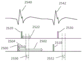
Fig. 25 schematically shows a time sequence of electrocardiogram and cardiac pacing signals and atrial and ventricular refractory periods, and indicates a time window for irreversible electroporation ablation, according to an embodiment.
Fig. 26A is a perspective view of an ablation catheter according to other embodiments. Fig. 26B is a side view of the ablation catheter depicted in fig. 26A positioned in the left atrium cavity of the heart adjacent the ostium. Fig. 26C is a simulated top view of the ablation catheter depicted in fig. 26B, showing selective electrode activation in accordance with an embodiment. Fig. 26D is a simulated illustration of tissue ablation in the lung orifice according to an embodiment.
Fig. 27A-27C are respective side views of ablation catheters according to other embodiments. Fig. 27A is a side view of an ablation catheter in a second configuration. Fig. 27B is another side view of the ablation catheter in a second configuration. Fig. 27C is yet another side view of an ablation catheter in a second configuration.
Fig. 28 is a side view of an ablation catheter according to other embodiments.
Fig. 29A-29D are cross-sectional side views of ablation catheters according to other embodiments. Fig. 29A is a cross-sectional side view of an ablation catheter in a first configuration. Fig. 29B is a cross-sectional side view of an ablation catheter in a third configuration. Fig. 29C is another cross-sectional side view of an ablation catheter in a third configuration. Fig. 29D is yet another cross-sectional side view of the ablation catheter in a third configuration.
Fig. 30 is a side view of an ablation catheter according to other embodiments.
Fig. 31A-31B are perspective views of ablation catheters according to other embodiments. Fig. 31A is a perspective view of an ablation catheter in a first configuration. Fig. 31B is a perspective view of an ablation catheter in a second configuration.
Fig. 32 is a schematic cross-sectional view of an ablation catheter in accordance with other embodiments.
Fig. 33A-33E are illustrative diagrams of ablation catheters according to other embodiments. Fig. 33A is a perspective view of an ablation catheter. Fig. 33B is a front view of the ablation catheter of fig. 33A. Fig. 33C is a cutaway perspective view of a spline of the ablation catheter of fig. 33A. Fig. 33D is a cross-sectional view of a spline of the ablation catheter of fig. 33A. Fig. 33E is a perspective view of the ablation catheter of fig. 33A positioned adjacent tissue.
34A-34B are side views of splines according to other embodiments. Fig. 34A is a side view of a spline having unit cut vectors. Fig. 34B is a side view of a spline having two unit cut vectors.
Fig. 35 is a side view of an ablation catheter according to other embodiments.
Fig. 36A-36C are side views of ablation catheters according to other embodiments. Fig. 36A is a side view of an ablation catheter in a second configuration. Fig. 36B is another side view of the ablation catheter in a second configuration. Fig. 36C is a side view of an ablation catheter near tissue.
Fig. 37A-37B are perspective views of an ablation catheter and left atrium. Fig. 37A is a perspective view of an ablation catheter positioned in the left atrium. Fig. 37B is a perspective view of the left atrium after tissue ablation.
Detailed Description
Described herein are systems, devices, and methods for selectively and rapidly applying a pulsed electric field to ablate tissue by irreversible electroporation. In general, the systems, devices, and methods described herein may be used to generate large electric field magnitudes at desired regions of interest and to reduce peak electric field values elsewhere to reduce unnecessary tissue damage and arcing. The irreversible electroporation systems described herein can include a signal generator and a processor configured to apply one or more voltage pulse waveforms to a selected set of electrodes of an ablation device to deliver energy to a region of interest (e.g., ablation energy for a set of tissues in a pulmonary vein ostium). The pulse waveforms disclosed herein may help treat various arrhythmias (e.g., atrial fibrillation). To deliver the pulse waveform generated by the signal generator, one or more electrodes of the ablation device may have insulated electrical leads configured to maintain a voltage potential of at least about 700V without dielectric breakdown to their corresponding insulation. The electrodes may be individually addressable such that each electrode may be controlled (e.g., delivering energy) independently of any other electrode of the device. In this way, the electrodes may cooperatively deliver different energy waveforms with different timing to electroporate the tissue.
As used herein, the term "electroporation" refers to the application of an electric field to a cell membrane to alter the permeability of the cell membrane to the extracellular environment. As used herein, the term "reversible electroporation" refers to the application of an electric field to a cell membrane to temporarily alter the permeability of the cell membrane to the extracellular environment. For example, cells undergoing reversible electroporation may observe the temporary and/or intermittent formation of one or more pores in their cell membrane that close upon removal of the electric field. As used herein, the term "irreversible electroporation" refers to the application of an electric field to a cell membrane to permanently alter the permeability of the cell membrane to the extracellular environment. For example, cells undergoing irreversible electroporation can observe the formation of one or more pores in their cell membrane that remain after the electric field is removed.
The pulse waveforms for electroporation energy delivery disclosed herein may enhance the safety, efficiency, and effectiveness of energy delivery to tissue by reducing the electric field threshold associated with irreversible electroporation, thereby producing more effective ablative lesions with reduced total energy delivered. In some embodiments, the voltage pulse waveforms disclosed herein may be hierarchical and have a nested structure. For example, the pulse waveform may comprise a hierarchical grouping of pulses having an associated time scale. In some embodiments, the methods, systems, and devices disclosed herein may include one or more of the methods, systems, and devices described in international application serial number PCT/US 2016/057664, filed on the date of 2016, 10, 19, and entitled "system, apparatus, and method for delivering ablative energy to tissue (SYSTEMS, APPARATUSES AND METHODS FOR DELIVERY OF ABLATIVE ENERGY TO TISSUE)", the contents of which are incorporated herein by reference in their entirety.
In some embodiments, the system may further comprise a cardiac stimulator for synchronizing the generation of the pulse waveform with the paced heartbeat. The cardiac stimulator may electrically pace the heart with the cardiac stimulator and ensure pacing capture to establish periodicity and predictability of the cardiac cycle. A time window within the refractory period of the periodic cardiac cycle may be selected for voltage pulse waveform delivery. Thus, the voltage pulse waveform may be delivered during the refractory period of the cardiac cycle to avoid interruption of the sinus rhythm of the heart. In some embodiments, the ablation device may include one or more catheters, guidewires, balloons, and electrodes. The ablation device may be converted to different configurations (e.g., compact and expanded) to position the device within the endocardial space. In some embodiments, the system may optionally include one or more return electrodes.
Typically, to ablate tissue, one or more catheters may be advanced through the vasculature to a target site in a minimally invasive manner. In cardiac applications, the electrodes through which the voltage pulse waveforms are delivered may be placed on an epicardial device or an endocardial device. The methods described herein may comprise introducing a device into the endocardial space of the left atrium of the heart and positioning the device in contact with the pulmonary vein ostia. A pulse waveform may be generated and delivered to one or more electrodes of the device to ablate tissue. In some embodiments, the pulse waveform may be generated in synchronization with the cardiac pacing signal to avoid disruption of the sinus rhythm of the heart. In some embodiments, the electrodes may be configured in the form of anode-cathode subsets. The pulse waveform may comprise a stepped waveform to aid tissue ablation and reduce damage to healthy tissue.
I. System and method for controlling a system
SUMMARY
Disclosed herein are systems and devices configured for tissue ablation that facilitate tissue ablation by selectively and rapidly applying voltage pulse waveforms to achieve irreversible electroporation. In general, the systems described herein for ablating tissue may include a signal generator and an ablation device having one or more electrodes for selectively and rapidly applying a DC voltage to drive electroporation. As described herein, the systems and devices may be deployed epicardially and/or endocardially to treat atrial fibrillation. A voltage may be applied to a selected subset of the electrodes, the anode electrode selection and the cathode electrode selection having independent subset selections. A pacing signal for cardiac stimulation may be generated by the signal generator in synchronization with the pacing signal and used to generate a pulse waveform.
Generally, the systems and devices described herein include one or more catheters configured to ablate tissue in the left atrial chamber of the heart. Fig. 1 illustrates an ablation system (100) configured to deliver a voltage pulse waveform. The system (100) may include a device (120) including a signal generator (122), a processor (124), a memory (126), and a cardiac stimulator (128). The apparatus (120) may be coupled to the ablation device (110), and optionally to the pacing device (130) and/or an optional return electrode (140) (e.g., a return pad shown here in phantom).
The signal generator (122) may be configured to generate a pulse waveform for irreversible electroporation of tissue (such as, for example, pulmonary vein ostia). For example, the signal generator (122) may be a voltage pulse waveform generator and deliver a pulse waveform to the ablation device (110). The return electrode (140) may be coupled to the patient (e.g., positioned on the patient's back) to allow current to flow from the ablation device (110) through the patient, and then to the return electrode (140) to provide a safe current return path from the patient (not shown). The processor (124) may combine data received from the memory (126), the cardiac stimulator (128), and the pacing device (130) to determine parameters (e.g., amplitude, width, duty cycle, etc.) of the pulse waveform to be generated by the signal generator (122). The memory (126) may further store instructions that cause the signal generator (122) to perform modules, processes, and/or functions associated with the system (100), such as pulse shape generation and/or cardiac pacing synchronization. For example, the memory (126) may be configured to store pulse waveform data and/or cardiac pacing data for pulse waveform generation and/or cardiac pacing, respectively.
In some embodiments, the ablation device (110) may include a catheter configured to receive and/or deliver a pulse waveform described in more detail below. For example, an ablation device (110) may be introduced into the endocardial space of the left atrium and positioned to align one or more electrodes (112) with one or more pulmonary vein ostia, and then deliver a pulse waveform to ablate tissue. The ablation device (110) may include one or more electrodes (112), which in some embodiments may be a set of individually addressable electrodes. Each electrode may include an insulated electrical lead configured to maintain a voltage potential of at least about 700V without dielectric breakdown to its corresponding insulation. In some embodiments, the insulation on each of the electrical leads may maintain a potential difference of between about 200V to about 1,500V across its thickness without creating dielectric breakdown. For example, the electrodes (112) may be grouped into one or more anode-cathode subsets, such as, for example, a subset comprising one anode and one cathode, a subset comprising two anodes and two cathodes, a subset comprising two anodes and one cathode, a subset comprising one anode and two cathode, a subset comprising three anodes and one cathode, a subset comprising three anodes and two cathodes, and the like.
The pacing device (130) may be suitably coupled to a patient (not shown) and configured to receive cardiac pacing signals generated by a cardiac stimulator (128) for cardiac stimulation of the apparatus (120). An indication of the pacing signal may be transmitted by the cardiac stimulator (128) to the signal generator (122). Based on the pacing signal, an indication of the voltage pulse waveform may be selected, calculated, and/or otherwise identified by a processor (124) and generated by a signal generator (122). In some embodiments, the signal generator (122) is configured to generate a pulse waveform in synchronization with the indication of the pacing signal (e.g., within a common refractory period window). For example, in some embodiments, the common refractory period window may begin substantially immediately after the ventricular pacing signal (or after a very small delay), and thereafter last for about 250 milliseconds or less. In such embodiments, the entire pulse waveform may be delivered for this duration.
The processor (124) may be any suitable processing device configured to execute and/or execute a set of instructions or code. The processor may be, for example, a general purpose processor, a Field Programmable Gate Array (FPGA), an Application Specific Integrated Circuit (ASIC), a Digital Signal Processor (DSP), or the like. The processor may be configured to run and/or execute application processes and/or other modules, processes, and/or functions associated with the system and/or a network (not shown) associated therewith. Underlying device technologies may be provided in a variety of component types, such as Metal Oxide Semiconductor Field Effect Transistor (MOSFET) technologies (e.g., complementary Metal Oxide Semiconductor (CMOS)), bipolar technologies (e.g., emitter-coupled logic (ECL)), polymer technologies (e.g., silicon conjugated polymers and metal conjugated polymer-metal structures), hybrid analog and digital, and the like.
The memory (126) may contain a database (not shown) and may be, for example, random Access Memory (RAM), memory buffers, hard disk drives, erasable programmable read-only memory (EPROM), electrically erasable read-only memory (EEPROM), read-only memory (ROM), flash memory, or the like. The memory (126) may store instructions that cause the processor (124) to execute modules, processes, and/or functions associated with the system (100), such as pulse waveform generation and/or cardiac pacing.
The system (100) may communicate with other devices (not shown) through, for example, one or more networks, each of which may be any type of network. A wireless network may refer to any type of digital network that is not connected by any type of cable. However, the wireless network may be connected to a wired network to interface with the internet, other carrier voice and data networks, business networks, and personal networks. Wired networks are typically carried by twisted pair copper wires, coaxial cable, or fiber optic cable. Many different types of wired networks exist, including Wide Area Networks (WANs), metropolitan Area Networks (MANs), local Area Networks (LANs), campus Area Networks (CAN), global Area Networks (GAN) (e.g., the internet), and Virtual Private Networks (VPN). In the following, a network refers to any combination of wireless, wired, public and private data networks that are typically interconnected by the internet to provide a unified networking and information access solution.
Ablation device
The systems described herein may include one or more multi-electrode ablation devices configured to ablate tissue in the left atrial chamber of the heart to treat atrial fibrillation. Fig. 2 is a perspective view of an ablation device (200) (e.g., similar in structure and/or function to ablation device (110)) including a catheter (210) and a guidewire (220) slidable within a lumen of catheter (210). The guidewire (220) may include a nonlinear distal portion (222), and the catheter (210) may be configured to rest on the guidewire (220) during use. The distal portion (222) of the guidewire (220) may be shaped to facilitate placement of the catheter (210) in a lumen of a patient. For example, the distal portion (222) of the guidewire (220) may be shaped to be placed in and/or near the pulmonary vein ostium, as described in more detail with reference to fig. 15. The distal portion (222) of the guidewire (220) may include and/or be formed into an atraumatic shape that reduces trauma to tissue (e.g., prevents and/or reduces the likelihood of tissue penetration). For example, the distal portion (222) of the guidewire (220) may comprise a non-linear shape, such as a circular shape, a ring shape (as shown in fig. 2), an oval shape, or any other geometric shape. In some embodiments, the guidewire (220) may be configured to be elastic such that a guidewire having a nonlinear shape may conform to the lumen of the catheter (210) when disposed in the catheter (210) and reform/otherwise regain the nonlinear shape when the catheter (210) is pushed out. In other embodiments, the catheter (210) may be similarly configured to be resilient, such as to aid in advancing the catheter (210) through a sheath (not shown). The shaped distal portion (222) of the guidewire (220) may be angled relative to the guidewire (220) and other portions of the catheter (210). The catheter (210) and guidewire (220) may be sized to be advanced into an endocardial space (e.g., the left atrium). The diameter of the shaped distal portion (222) of the guidewire (220) may be about the same as the diameter of the lumen into which the catheter (230) is to be placed.
The catheter (210) may be slidably advanced over the guidewire (220) for placement over the guidewire (220) during use. A distal portion (222) of a guidewire (220) disposed in a lumen (e.g., near a pulmonary vein ostium) may act as a stop for advancement of the distal portion of the catheter (210). The distal portion of the catheter (210) may include a set of electrodes (212) (e.g., similar in structure and/or function to the one or more electrodes (112)) configured to contact an inner radial surface of a lumen (e.g., a pulmonary vein ostium). For example, the electrode (212) may include an approximately circular electrode arrangement configured to contact the pulmonary vein ostium. As shown in fig. 2, one or more of the electrodes (212) may comprise a series of metal strips or rings disposed along the catheter shaft and electrically connected together. For example, the ablation device (200) may include a single electrode having multiple bands, one or more electrodes each having its own band, and combinations thereof. In some embodiments, the electrode (212) may be shaped to conform to the shape of the distal portion (222) of the guidewire (220). The catheter shaft may contain a flexible portion between the electrodes for enhancing flexibility. In other embodiments, one or more of the electrodes (212) may include a spiral winding for enhanced flexibility.
Each of the electrodes of the ablation devices discussed herein may be connected to an insulated electrical lead (not shown) such that a handle (not shown) is coupled to the proximal portion of the catheter. The insulation on each of the electrical leads can maintain a potential difference of at least 700V across its thickness without creating dielectric breakdown. In other embodiments, the insulation on each of the electrical leads may maintain a potential difference of between about 200V and about 2000V across its thickness, including all values and subranges therebetween, without creating dielectric breakdown. This allows the electrodes to efficiently deliver electrical energy and ablate tissue by irreversible electroporation. The electrodes may, for example, receive a pulse waveform generated by a signal generator (122), as discussed above with reference to fig. 1. In other embodiments, the guidewire (220) may be separate from the ablation device (200) (e.g., the ablation device (200) contains the catheter (210), but does not contain the guidewire (220)). For example, the guidewire (220) may be self-advancing into the endocardial space, and thereafter, the catheter (210) may be advanced through the guidewire (220) into the endocardial space.
Fig. 3 is a perspective view of another embodiment of an ablation device (300) (e.g., similar in structure and/or function to the ablation device (110)) including a catheter (310) having a set of electrodes (314) disposed along a distal portion (312) of the catheter (310). The distal portion (312) of the catheter (310) may be nonlinear and form an approximately circular shape. A set of electrodes (314) may be disposed along the nonlinear distal portion (312) of the catheter (310) and may form a generally circular arrangement of electrodes (314). During use, the electrode (314) may be positioned at the ostium of a pulmonary vein to deliver a pulse waveform to ablate tissue, as described in more detail with reference to fig. 16. The shaped distal portion (312) of the catheter (310) may be angled relative to other portions of the catheter (310). For example, the distal portion (312) of the catheter (310) may be substantially perpendicular to the adjacent portion of the catheter (310). In some embodiments, a handle (not shown) may be coupled to a proximal portion of the catheter (310) and may include a bending mechanism (e.g., one or more pull wires (not shown)) configured to modify a shape of a distal portion (312) of the catheter (310). For example, a pull wire operating the handle may increase or decrease the circumference of the circular shape of the distal portion (312) of the catheter (310). The diameter of the distal portion (312) of the catheter (310) may be modified to allow the electrode (314) to be positioned adjacent to and/or in contact with the ostium of the pulmonary vein (e.g., in contact with the inner radial surface of the pulmonary vein). The electrodes (314) may comprise a series of metal strips or rings and are individually addressable.
In some embodiments, the pulse waveform may be applied between electrodes (314) configured in anode and cathode sets. For example, adjacent or approximately diametrically opposed pairs of electrodes may be activated together as an anode-cathode set. It should be appreciated that any of the pulse waveforms disclosed herein may be applied progressively or sequentially to a series of anode-cathode electrodes.
Fig. 4 is a perspective view of yet another embodiment of an ablation device (400) (e.g., similar in structure and/or function to ablation device (110)) including a catheter (410) and a guidewire (420) having a shaped nonlinear distal portion (422). The guidewire (420) may be slid within the lumen of the catheter (410). The guidewire (420) may be advanced through the lumen of the catheter (410), and the distal portion (422) of the guidewire (420) may be approximately circular. The shape and/or diameter of the distal portion (422) of the guidewire (420) may be modified using the bending mechanism as described above with reference to fig. 3. The catheter (410) may be flexible so as to be deflectable. In some embodiments, the catheter (410) and/or guidewire (420) may be configured to be resilient such that it conforms to the lumen in which it is placed and assumes a second shape when the lumen is pushed out. By modifying the size of the guidewire (420) and manipulating the deflection of the catheter (410), the distal portion (422) of the guidewire (420) may be positioned at a target tissue site, such as a pulmonary vein ostium. The distal end (412) of the catheter (410) may be sealed (except where the guidewire (420) extends) such that the catheter (410) may electrically insulate portions of the guidewire (420) within the lumen of the catheter (410). For example, in some embodiments, the distal end (412) of the catheter (410) may include a seal with an opening that allows the guidewire (420) to pass through when a force is applied to form a compression holder (which may be liquid-tight) between the seal and the guidewire (420).
In some embodiments, an exposed distal portion (422) of the guidewire (420) may be coupled to the electrode and configured to receive a pulse waveform from the signal generator and deliver the pulse waveform to tissue during use. For example, the proximal end of the guidewire (420) may be coupled to a suitable lead and connected to the signal generator (122) of fig. 1. The distal portion (422) of the guidewire (420) may be sized such that it may be positioned at the pulmonary vein ostia. For example, the diameter of the shaped distal portion (422) of the guidewire (420) may be about the same as the diameter of the pulmonary vein ostium. The shaped distal portion (422) of the guidewire (420) may be angled relative to the guidewire (420) and other portions of the catheter (410).
The guidewire (420) may comprise stainless steel, nitinol, platinum, or other suitable biocompatible materials. In some embodiments, the distal portion (422) of the guidewire (420) may include a platinum coil physically and electrically attached to the guidewire (420). The platinum coil may be an electrode configured to deliver a voltage pulse waveform. Platinum is radiopaque and its use may add flexibility to assist in advancing and positioning the ablation device (400) within the endocardial space.
Fig. 5 is a detailed perspective view of a flower-shaped distal portion of an ablation device (500) (e.g., similar in structure and/or function to the ablation device (110)) that includes a set of electrodes (520, 522, 524, 526) each extending from a pair of insulated lead segments (510, 512, 514, 516). Each pair of adjacent insulated lead segments coupled to uninsulated electrodes (e.g., lead segments (510, 512) and electrode (526)) form a loop (fig. 5 shows a set of four loops). The set of loops at the distal portion of the ablation device (500) may be configured to deliver a pulse waveform to tissue. The ablation device (500) may include a set of insulated lead segments (510, 512, 514, 516) that diverge at the distal end of the device (500) to connect to respective exposed electrodes (520, 522, 524, 526), as shown in fig. 5. The electrodes (520, 522, 524, 526) may include exposed portions of electrical conductors. In some embodiments, one or more of the electrodes (520, 522, 524, 526) may comprise a platinum coil. One or more segments (510, 512, 514, 516) may be coupled to a bending mechanism (e.g., struts, pull wires, etc.) controlled by a handle (not shown) to control the size and/or shape of the distal portion of the device (500).
The electrodes (520, 522, 524, 526) may be flexible and form a compact first configuration to be pushed into the endocardial space, such as adjacent to the pulmonary vein ostia. Once positioned at the desired location, the electrodes (520, 522, 524, 526) can be converted to an expanded second configuration when pushed out of the lumen (e.g., sheath) to form a flower-shaped distal portion as shown in fig. 5. In other embodiments, the insulated lead segments (510, 512, 514, 516) and electrodes (520, 522, 524, 526) may be biased to expand (e.g., spring open) outwardly into the second configuration when pushed out of the lumen (e.g., sheath) of the carrier (500). The electrodes (520, 522, 524, 526) may be individually addressable and each electrode has insulated electrical leads configured to maintain a voltage potential of at least about 700V without dielectric breakdown to its corresponding insulation. In other embodiments, the insulation on each of the electrical leads may maintain a potential difference between about 200V to about 2000V across the thickness without creating dielectric breakdown.
In some embodiments, the ablation device (5000) may be configured to deliver a pulse waveform to tissue through the set of electrodes (520, 522, 524, 526) during use. In some embodiments, the pulse waveform may be applied between electrodes (520, 522, 524, 526) configured in anode and cathode sets. For example, approximately diametrically opposed pairs of electrodes (e.g., electrodes (520, 524) and (522, 526)) may be activated together as an anode-cathode pair. In other embodiments, adjacent electrodes may be configured as anode-cathode pairs. As an example, a first electrode (520) of the set of electrodes may be configured as an anode and a second electrode (522) may be configured as a cathode.
Fig. 6-9E, 26A-27C, and 28 illustrate further embodiments of an ablation device (e.g., similar in structure and/or function to ablation device (110)) that may be configured to deliver a voltage pulse waveform using a set of electrodes to ablate tissue and electrically isolate pulmonary veins. In some of these embodiments, the ablation device may be transitioned from a first configuration to a second configuration such that electrodes of the ablation device expand outward to contact a lumen of tissue (e.g., a pulmonary vein ostium).
Fig. 6 is a side view of an embodiment of an ablation device (600) including a catheter shaft (610) at a proximal end of the device (600), a distal cap (612) of the device (600), and a set of splines (614) coupled thereto. The distal cap (612) may include an atraumatic shape to reduce trauma to tissue. The proximal end of the set of splines (614) may be coupled to the distal end of the catheter shaft (610), and the distal end of the set of splines (614) may be tethered to a distal cap (612) of the device (600). The ablation device (600) may be configured to deliver a pulse waveform to tissue through one or more splines of the set of splines (614) during use. As used herein, the terms "spline" and "spine" are used interchangeably. In some embodiments, the apparatus may include a catheter defining a longitudinal axis.
Each spline (614) of the ablation device (600) may include one or more electrodes (616) formed on a surface of the spline (614) that are commonly connected by wires, or in some cases, individually addressable electrodes. Each electrode (616) may include an insulated electrical lead configured to maintain a voltage potential of at least about 700V without dielectric breakdown to its corresponding insulation. In other embodiments, the insulation on each of the electrical leads may maintain a potential difference between about 200V to about 2000V across the thickness without creating dielectric breakdown. Each spline (614) may contain an insulated electrical lead for each electrode (616) formed in the body of the spline (614) (e.g., within the lumen of the spline (614)). In the case where electrodes on a single spline are wired together, a single insulated lead may carry a wire harness connected to different electrodes on the spline. Fig. 6 shows a set of splines (614), wherein each spline (614) contains a pair of electrodes (616) having about the same size, shape, and spacing as the electrodes (616) of adjacent splines (614). In other embodiments, the size, shape, and spacing of the electrodes (616) may be different.
For each of the ablation devices described herein, and in particular the ablation devices described in fig. 6-9E, 26A-27C, and 28, each spline of the set of splines may comprise a flexible curvature. The minimum radius of curvature of the spline may range from about 1cm or more. For example, the set of splines may form a delivery assembly at a distal portion of an ablation device and be configured to transition between a first configuration in which the set of splines is bent radially outward from a longitudinal axis of the ablation device and a second configuration in which the set of splines is arranged substantially parallel to the longitudinal axis of the ablation device. In this way, the spline can more easily conform to the geometry of the endocardial space. In general, a splined "basket" may have an asymmetric shape along the length of the shaft such that one end (e.g., distal end) of the basket is more spherical than the other end (e.g., proximal end) of the basket. The delivery assembly may be disposed in contact with the pulmonary vein ostium in the first configuration and converted to a second configuration prior to delivering a pulse waveform. In some of these embodiments, a handle may be coupled to the set of splines, and the handle is configured to affect a transition of the set of splines between the first configuration and the second configuration. In some embodiments, electrical leads of at least two electrodes of the set of electrodes may be electrically coupled at or near a proximal portion of the ablation device, such as, for example, within the handle.
In one embodiment, each of the electrodes (616) on a spline (614) may be configured as an anode, while each of the electrodes (616) on an adjacent spline (614) may be configured as a cathode. In another embodiment, electrodes (616) on one spline may alternate between anodes and cathodes, with electrodes of adjacent splines having opposite configurations (e.g., cathodes and anodes). The ablation device (600) may include any number of splines, such as 3, 4, 5, 6, 7, 8, 9, 10, 12, 14, 16, 18, 20, or more splines, including all values and subranges therebetween. In some embodiments, the ablation device (600) may contain 3 to 20 splines. For example, the ablation device (600) may contain 6 to 12 splines.
Fig. 7 is a side view of another embodiment of an ablation device (700) including a catheter shaft (710) at a proximal end of the device (700), a distal cap (712) of the device (700), and a set of splines (714) coupled thereto. The distal cap (712) may include an atraumatic shape. The proximal end of the set of splines (714) may be coupled to the distal end of the catheter shaft (710), and the distal end of the set of splines (714) may be tethered to a distal cap (712) of the device (700). Each spline (714) of the ablation device (700) may include one or more individually addressable electrodes (716) formed on a surface of the spline (714). Each electrode (716) may include an insulated electrical lead configured to maintain a voltage potential of at least about 700V without dielectric breakdown to its corresponding insulation. In other embodiments, the insulation on each of the electrical leads may maintain a potential difference between about 200V to about 1500V across the thickness without creating dielectric breakdown. Each spline (714) may contain an insulated electrical lead for each electrode (716) formed in the body of the spline (714) (e.g., within the lumen of the spline (714)). A set of spline wires (718, 719) may be electrically conductive and electrically couple adjacent electrodes (716) disposed on different splines (714) (e.g., electrodes (716) between a pair of splines (718, 719) of the set of splines). For example, the spline leads (718, 719) may extend in a transverse direction relative to a longitudinal axis of the ablation device (700).
Fig. 7 shows a set of splines (714), wherein each spline (714) contains a pair of electrodes (716) having about the same size, shape and spacing as the electrodes (716) of adjacent splines (714). In other embodiments, the size, shape, and spacing of the electrodes (716) may be different. For example, the electrode (716) electrically coupled to the first spline wire (718) may be different in size and/or shape than the electrode (716') electrically coupled to the second spline wire (719).
In some embodiments, the first spline wire (718) may comprise a first set of spline wires (720, 721, 722, 723), wherein each spline wire of the set of spline wires (720, 721, 722, 723) may couple the electrode (716) between a different pair of splines of the set of splines (714). In some of these embodiments, the set of spline wires (720, 721, 722, 723) may form a continuous loop between electrodes (716) coupled thereto. Similarly, the second spline wire (719) may comprise a second set of spline wires (724, 725, 726), wherein each spline wire of the set of spline wires (724, 725, 726) may be coupled across an electrode (716') of the set of splines (714). The second set of spline wires (724, 725, 726) may be coupled to a different electrode (716') across the set of spline wires (714) than the first set of spline wires (720, 721, 722, 723). In some of these embodiments, the first set of spline wires (720, 721, 722, 723) may form a first continuous loop between electrodes (716) coupled thereto, and the second set of spline wires (724, 725, 726) may form a second continuous loop between electrodes (716') coupled thereto. The first continuous loop may be electrically isolated from the second continuous loop. In some of these embodiments, the electrode (716) coupled to the first continuous loop may be configured as an anode and the electrode (716) coupled to the second continuous loop may be configured as a cathode. The pulse waveform may be delivered to electrodes (716) of the first continuous loop and the second continuous loop. In some embodiments, the spline leads (e.g., 721, 722, 723, etc.) may be replaced by similar electrical connections in the proximal portion of the device (e.g., in the device handle). For example, electrodes 716 may all be electrically wired together in the handle of the device.
In another embodiment, a first spline wire (721) of the set of spline wires (720, 721, 722, 723) may couple an electrode (716) between a first spline (711) and a second spline (713) of the set of splines (714), and a second spline wire (720) of the set of spline wires (720, 721, 722, 723) may couple an electrode (716) between the first spline (711) and a third spline (715) of the set of splines (714). The electrode (716) coupled by the first spline lead (721) and the second spline lead (720) may be configured as an anode and a cathode (or vice versa). In yet another embodiment, a first spline wire (721) of the set of spline wires (720, 721, 722, 723) may couple an electrode (716) between a first spline (711) and a second spline (713) of the set of splines (714), and a second spline wire (723) of the set of spline wires (720, 721, 722, 723) may couple an electrode (716) between a third spline (715) and a fourth spline (717) of the set of splines (714). The pulse waveform may be delivered to an electrode (716) coupled by a first spline lead (721) and a second spline lead (723). In some embodiments, instead of a spline lead, the electrical leads of at least two electrodes of the set of electrodes are electrically coupled at or near a proximal portion of the ablation device, such as, for example, within a handle.
In other embodiments, one or more of the spline leads (718, 719) may form a continuous loop between the electrically coupled electrodes (716). For example, a first set of spline wires (718) may form a first continuous loop between electrodes (716) coupled thereto, and a second set of spline wires (719) may form a second continuous loop between electrodes (716) coupled thereto. In this case, the first continuous loop may be electrically isolated from the second continuous loop. In one embodiment, each of the electrodes (716) coupled to the first set of spline leads (718) may be configured as anodes, and each of the electrodes (716) coupled to the second set of spline leads (719) may be configured as cathodes. Each set of electrically coupled electrodes (716) may be individually addressable. In some embodiments, instead of a spline lead, the electrical leads of at least two electrodes of the set of electrodes are electrically coupled at or near a proximal portion of the ablation device, such as, for example, within a handle.
In some embodiments, as discussed in further detail below with reference to fig. 8A-8B, the spline leads may be electrically coupled to a set of electrodes (e.g., 2, 3, 4, 5, etc.) without forming a continuous loop. For example, two spline wires may be used to form a discontinuous loop. In other embodiments, the size, shape, and spacing of the electrodes (716) may be different. The ablation device (700) may include any number of splines, such as 3, 4, 5, 6, 7, 8, 9, 10, 12, 14, 16, 18, 20, or more splines. In some embodiments, the ablation device (700) may include 3 to 20 splines. For example, in one embodiment, the ablation device (700) may contain 6 to 9 splines.
Fig. 8A-8B are side and front cross-sectional views, respectively, of an ablation catheter (800). Fig. 8A is a side view of an embodiment of an ablation device (800) including a catheter shaft (810) at a proximal end of the device (800), a distal cap (812) of the device (800), and a set of splines (814) coupled thereto. The distal cap (812) may include an atraumatic shape. The proximal end of the set of splines (814) may be coupled to the distal end of the catheter shaft (810), and the distal end of the set of splines (14) may be tethered to a distal cap (812) of the device (800). Each spline (814) of the ablation device (800) may include one or more independently addressable electrodes (816, 818) formed on a surface of the spline (814). Each electrode (816, 818) may include an insulated electrical lead configured to maintain a voltage potential of at least about 700V without dielectric breakdown to its corresponding insulation. In other embodiments, the insulation on each of the electrical leads may maintain a potential difference of between about 200V and about 2000V across its thickness, including all values and subranges therebetween, without creating dielectric breakdown. Each spline (814) may contain an insulated electrical lead for each electrode (816, 818) formed in the body of the spline (814) (e.g., within the lumen of the spline (814)). One or more spline leads (817, 819) may be electrically conductive and electrically couple adjacent electrodes (816, 818) disposed on different splines (814). For example, the spline leads (817, 819) may extend in a lateral direction relative to a longitudinal axis of the ablation device (800).
FIG. 8B is a front cross-sectional view of FIG. 8A taken along line 8B-8B. Each spline wire (817, 819, 821, 823) electrically couples a pair of adjacent electrodes (816, 818, 820, 822) on a different spline. In some embodiments, each coupled electrode pair may be electrically isolated from each other. In some embodiments, the coupled electrode pairs may be configured to have a common polarity. The electrodes of adjacent pairs may be configured to have opposite polarities (e.g., a first electrode pair is configured as an anode and an adjacent second electrode pair is configured as a cathode). For example, the electrode (816) coupled to the first set of spline leads (817) may be configured as an anode, while each of the electrodes (818) coupled to the second set of spline leads (819) may be configured as a cathode. In some embodiments, each electrode formed on the spline (814) may share a common polarity (e.g., configured as an anode or cathode). Each coupled electrode pair may be independently addressable. In some embodiments, the ablation device (800) may include an even number of splines. The ablation device (800) may include any number of splines, such as 4, 6, 8, 10, or more splines. In some embodiments, the ablation device may contain 4 to 10 splines. For example, in one embodiment, the ablation device may include 6 to 8 splines. As previously described, in some embodiments, the spline leads (e.g., 817, 819, etc.) may be replaced by similar electrical connections in the proximal portion of the device (e.g., in the device handle). For example, electrodes (816) may be electrically wired together in the handle of the device such that the electrodes are at the same potential during ablation.
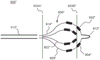
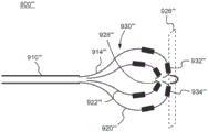
Fig. 9A is a side view of yet another embodiment of an ablation device (900) including a catheter shaft (910) at a proximal end of the device (900), a distal cap (912) of the device (900), and a set of splines (914) coupled thereto. The distal cap (912) may include an atraumatic shape. The proximal end of the set of splines (914) may be coupled to the distal end of the catheter shaft (910), and the distal end of the set of splines (914) may be tethered to a distal cap (912) of the device (900). Each spline (914) of the ablation device (900) may include one or more independently addressable electrodes (916, 918) formed on a surface of the spline (914). Each electrode (916, 918) may include an insulated electrical lead configured to maintain a voltage potential of at least about 700V without dielectric breakdown to its corresponding insulation. In other embodiments, the insulation on each of the electrical leads may maintain a potential difference between about 200V to about 2000V across the thickness without creating dielectric breakdown. Each spline (914) may contain an insulated electrical lead for each electrode (916, 918) formed in the body of the spline (914) (e.g., within the lumen of the spline (914)). Fig. 9A shows a set of splines (914), wherein each spline (914) contains an electrode that is spaced from or offset from the electrode of an adjacent spline (914). For example, the set of splines (914) includes a first spline (920) and a second spline (922) adjacent to the first spline (920), wherein an electrode (916) of the first spline (920) is disposed closer to a distal end (912) of the ablation device (900) than an electrode (918) of the second spline (922). In other embodiments, the size and shape of the electrodes (916, 918) may also be different.
In some embodiments, adjacent distal (916) and proximal (918) electrodes may form an anode-cathode pair. For example, the distal electrode (916) may be configured as an anode and the proximal electrode (918) may be configured as a cathode. In some embodiments, the ablation device (900) may contain 3 to 12 splines. In fig. 9A, one electrode (916, 918) is formed on the surface of each spline (914) such that each spline (914) contains one insulated electrical lead. The diameter of the spline (914) lumen may thus be reduced and allow the spline (914) to be thicker and mechanically stronger. Thus, dielectric breakdown of the insulation may be further reduced, thereby improving the reliability and lifetime of each spline (914) and ablation device (900). The ablation device (900) may include any number of splines, such as 3, 4, 5, 6, 7, 8, 9, 10, 12, 14, 16, 18, 20, or more splines. In some embodiments, the ablation device (900) may contain 3 to 20 splines. For example, in one embodiment, the ablation device (900) may include 6 to 10 splines. Further, in some embodiments, the shape of the spherically shaped expanded structure (930) of the expanded set of splines (914) may be asymmetric, e.g., its distal portion more spherically shaped or rounded than its proximal portion (see, e.g., fig. 9B-9E). Such a bulbous distal portion may help position the device at the ostium of a pulmonary vein.
Referring to fig. 9B-9E, it should be appreciated that components with reference numbers similar to those in fig. 9A (e.g., electrode (916) in fig. 9A and electrode (916') in fig. 9B) may be similar in structure and/or function unless otherwise indicated. Fig. 9B shows the spline wires (914 ',920',922 ') forming an expanded structure (930') during use (e.g., when deployed). The cross-sectional area of the first plane (924A '), sometimes also referred to as the proximal plane, of the expanded structure (930') is different than the cross-sectional area at the second plane (924B ') of the expanded structure (930'). As shown in fig. 9B, in some embodiments, the expanded structure (930 ') has a cross-sectional area at the second plane (924B ') that is greater than its cross-sectional area at the first plane (924A '). As used with reference to fig. 9B, the terms "first plane" and "second plane" may refer to planes orthogonal to the longitudinal axis of the catheter shaft (910 '), each formed up to about 1cm, about 2cm, and about 3cm or more (including all values and subranges therebetween) from the distal end of the catheter shaft (910 ') and the proximal end of the distal cap (912 '), respectively. Similar to fig. 9A, the electrode (916 ') of the first spline (920') is disposed closer to the distal cap (912 ') of the ablation device (900') than the electrode (918 ') of the second spline (922').
Fig. 9C shows the spline wires (914 ",920",922 ") forming an expanded structure (930") during use (e.g., when deployed). The cross-sectional area of a first plane (924A ') (sometimes referred to as a proximal plane) of the expanded structure (930') is different than the cross-sectional area at a second plane (924B ') of the expanded structure (930'). As shown in fig. 9C, in some embodiments, the expanded structure (930 ") has a larger cross-sectional area at the second plane (924B") than at the first plane (924A "). As used with reference to fig. 9C, the terms "first plane" and "second plane" may refer to planes orthogonal to the longitudinal axis of the catheter shaft (910 "), each formed up to about 1cm, about 2cm, and about 3cm or more (including all values and subranges therebetween), respectively, from the distal end of the catheter shaft (910") and the proximal end of the distal cap (912 "). 9A-9B, multiple electrodes may be present on each spline wire, and some electrodes may be equidistant from the distal cap (912 "). In this way, relatively distal electrodes (e.g., 932 "and 934") may be placed at the ostium of the pulmonary vein or proximal/sinus of the ostium during use for ablation delivery to create a ostial circumferential lesion around the pulmonary vein.
Fig. 9D shows spline wires (914 '", 920'", 922 '") that form an expanded structure (930'") during use (e.g., when deployed). Spline leads (914 ',920 ',922 ' ") at its distal end to a point (928 '") located within/within the expanded structure (930 ' "). In this configuration, as shown in fig. 9D, at least some of the electrodes (932 ' ", 934 '") on the spline leads (914 ' ", 920 '", 922 ' ") can be located in a distal plane (926 '") of the expanded structure (930 ' "). As used with reference to fig. 9D, the term "distal plane" may refer to a plane orthogonal to the longitudinal axis of the catheter shaft (910 '") that passes through the distal boundary of the expanded structure (930'"). In this way, the expanded structure (930' ") may be pressed against, for example, an endocardial surface (e.g., the left atrial back wall) to create lesions directly thereon by activating appropriate electrodes in the distal plane using any suitable combination of polarities. For example, the distal electrodes (932 '", 934'") may be pressed against endocardial surfaces and used to form lesions (e.g., spot lesions) by focal ablation.
Referring now to the use of an ablation device (900 ' ") to create a focal ablation lesion, in some embodiments, electrodes (933, 935) (sometimes also referred to as" proximal electrodes ") and electrodes (932 '", 934 ' ") (sometimes also referred to as" distal electrodes ") may be activated with opposite polarities. Conduction between these electrodes through the blood pool results in the generation of an electric field and the application of the electric field as ablative energy to the endocardial surface at the distal plane (926' ") resulting in focal ablation. So that it is distal electrode (932 ' ", so that the distal electrode (932 '", 934 ' ") is located at or within the distal plane (926 '") of the endocardial surface, while the proximal electrode (933, 935) is located outside the distal plane (926 ' ") and therefore does not press against or otherwise contact the endocardial surface. In some embodiments, the distal electrodes (932 '", 934'") may have the same polarity, while the adjacent proximal electrodes (935, 933) may have opposite polarity to the distal electrodes (932 '", 934'").
In some embodiments, the length of the electrodes of the ablation device (900' ") may be from about 0.5mm to about 5.0mm and the cross-sectional dimension (e.g., diameter) may be from about 0.5mm to about 2.5mm, including all values and subranges therebetween. The cross-sectional dimensions of the spline wires (914 '", 920'", 922 '") in the expanded structure (930'") shown in fig. 9D (e.g., diameter) may be about 6.0mm to about 30.0mm, including all values and subranges therebetween. The focal ablation lesions formed in this manner may have a diameter of between about 0.5cm and about 2.5cm, inclusive of all values and subranges therebetween.
In some embodiments, the distal electrode (932 '", 934'") may be configured to have opposite polarity. In some embodiments, adjacent electrodes on the same spline may have the same polarity such that distal electrode (934 '") may have the same polarity as proximal electrode (933), as well as distal electrode (932'") may have the same polarity as proximal electrode (935). The electrodes (934 '", 933) may have a polarity opposite to that of the electrodes (932'", 935).
In some embodiments, adjacent distal (934' ") and proximal (933) electrodes may form an anode-cathode pair. For example, the distal electrode (934' ") may be configured as an anode and the proximal electrode (933) may be configured as a cathode. In another embodiment, electrodes (2630) on one spline may alternate between anodes and cathodes, with electrodes of adjacent splines having opposite configurations (e.g., cathodes and anodes).
Fig. 9E shows spline wires (944, 940, 942) that form an expanded structure (950) during use (e.g., when deployed). The spline leads (944, 940, 942) converge at their distal ends at the proximal end of a distal cap (912 "") inside/within the expanded structure (950). In this configuration, as shown in fig. 9E, at least some of the electrodes (952, 954) on the spline leads (944, 940) may be located in a distal plane (946) of the expanded structure (950). As used with reference to fig. 9E, the term "distal plane" may refer to a plane orthogonal to the longitudinal axis of the catheter shaft (910 "") that passes through the distal boundary of the expanded structure (950). In this way, the expanded structure (950) may be pressed against, for example, the left atrial back wall to create lesions directly thereon by activating appropriate electrodes in the distal plane (946) using any suitable combination of polarities. For example, electrodes 952 and 954 may be configured to have opposite polarities. The expanded structure (950) in fig. 9E has a more orthogonal (e.g., flattened) shape relative to the expanded structure (930 "") in fig. 9D, which may be pressed against, for example, the left atrial back wall for tissue ablation. In other words, the cross-sectional area of the expanded structure (930 "") at the distal plane (926 "") is less than the cross-sectional area of the expanded structure (950) at the distal plane (946). As another example, the distal electrodes (952, 954) may be pressed against an endocardial surface and used to form lesions (e.g., spot lesions) by focal ablation, as generally described herein with respect to fig. 9D.
For each of the ablation devices described herein, each of the splines may comprise a polymer and define a lumen to form a hollow tube. One or more electrodes of the ablation devices described herein may comprise a diameter of about 0.2mm to about 2.0mm and a length of about 0.2mm to about 5.0 mm. In some embodiments, the electrode may comprise a diameter of about 1mm and a length of about 1 mm. Since the electrodes may be individually addressable, the electrodes may be energized in any order using any pulse waveform sufficient to ablate tissue by irreversible electroporation. For example, different sets of electrodes may deliver different sets of pulses (e.g., stepped pulse waveforms), as discussed in further detail below. It should be appreciated that the size, shape, and spacing of the electrodes on and between the splines may be configured to deliver continuous/transmural energy to electrically isolate one or more pulmonary veins. In some embodiments, the alternating electrodes (e.g., all distal electrodes) may be at the same potential, and so on for all other electrodes (e.g., all proximal electrodes). Thus, ablation can be delivered quickly with all electrodes activated simultaneously. There are a variety of such electrode pairing options, and the options may be implemented based on their convenience.
Fig. 26A is a perspective view of an embodiment of an ablation device (2600) having a flower-like shape and including a catheter shaft (2610) at a proximal end of the device (2600), a distal cap (2612) of the device (2600), and a set of splines (2620) coupled thereto. As best shown in fig. 26B, the spline shaft (2614) may be coupled to a proximal handle (not shown) at a proximal end and to a distal cap (2612) at a distal end. In a preferred embodiment, the distance between the distal cap (2612) and the catheter shaft (2610) may be less than about 8mm. The spline shaft (2614) and distal cap (2612) may translate along a longitudinal axis (2616) of the ablation device (2600). The spline shaft (2614) and distal cap (2612) may move together. The spline shaft (2614) may be configured to slide within a lumen of the catheter shaft (2610). The distal cap (2612) may contain an atraumatic shape to reduce trauma to tissue. The proximal end of each spline of the set of splines (2620) may pass through the distal end of the catheter shaft (2610) and may be tethered to the catheter shaft within the catheter shaft lumen, and the distal end of each spline of the set of splines (2620) may be tethered to the distal cap (2612) of the device (2600). The ablation device (2600) may be configured to deliver a pulse waveform to tissue through one or more splines of the set of splines (2620) during use, as disclosed in fig. 21-25, for example.
In some embodiments, each spline (2620) of the ablation device (2600) may include one or more commonly wired electrodes (2630) formed on a surface of the spline (2620). In other embodiments, one or more of the electrodes (2630) on a given spline may be individually addressable electrodes (2630). Each electrode (2630) may include an insulated electrical lead configured to maintain a voltage potential of at least about 700V without dielectric breakdown to its corresponding insulation. In other embodiments, the insulation on each of the electrical leads may maintain a potential difference between about 200V to about 2000V across the thickness without creating dielectric breakdown. Each spline (2620) may contain an insulated electrical lead for each electrode (2630) within the spline (2620) body (e.g., within the spline (2620) lumen). Fig. 26A shows a set of splines (2620), wherein each spline contains a set of electrodes (2632 or 2634) having about the same size, shape, and spacing as electrodes (2634 or 2632) of adjacent splines (2620). In other embodiments, the size, shape, and spacing of the electrodes (2632, 2634) may be different. The thickness of each spline (2620) may vary based on the number of electrodes (2630) formed on each spline (2620), which may correspond to the number of insulated electrical leads in the spline (2620). The splines (2620) may be of the same or different materials, thicknesses, and/or lengths.
Each spline of the set of splines (2620) may include a flexible curvature for rotation, or twist and bend and form petal-like curves, as shown in fig. 26A-26C. The minimum radius of curvature of the spline in the petaloid configuration may range from about 7mm to about 25mm. For example, the set of splines may form a delivery assembly at a distal portion of the ablation device (2600) and be configured to transition between a first configuration in which the set of splines is arranged substantially parallel to a longitudinal axis of the ablation device (2600) and a second configuration in which the set of splines rotates about the longitudinal axis of the ablation device (2600), or twists and bends and is substantially offset from the longitudinal axis. In the first configuration, each spline of the set of splines may lie in one plane with the longitudinal axis of the ablation device. In the second configuration, each spline of the set of splines may be offset away from the longitudinal axis to form a petal-like curve arranged generally perpendicular to the longitudinal axis. In this way, the set of splines (2620) twist, bend, and bias away from the longitudinal axis of the ablation device (2600), allowing the splines (2620) to more easily conform to the geometry of the endocardial space and in particular adjacent to the ostium opening. The second configuration may, for example, resemble a flower shape when the ablation device is viewed from the front, as best shown in fig. 26C. In some embodiments, each spline of the set of splines in the second configuration may twist and bend to form a petal-like curve that shows an angle of more than 180 degrees between the proximal and distal ends of the curve when viewed from the front. The set of splines further may be configured to transition from the second configuration to a third configuration in which the set of splines (2620) may imprint (e.g., contact) a target tissue, such as tissue surrounding a pulmonary vein ostium.
In some embodiments, a spline shaft (2614) coupled to the set of splines (2620) may allow each spline in the set of splines (2620) to bend and twist relative to the catheter shaft (2610) as the spline shaft (2614) slides within the lumen of the catheter shaft (2610). For example, the set of splines (2620) may form a shape that is generally parallel to the longitudinal axis of the spline shaft (2614) when undeployed, may wrap (e.g., helically twist) about an axis (2660) that is parallel to the longitudinal axis of the spline shaft (2620) when fully deployed, and form any intermediate shape (e.g., a cage or barrel) therebetween when the spline shaft (2614) slides within the lumen of the conduit shaft (2610).
In some embodiments, the set of splines (e.g., splines (2620)) in the first configuration may be wound about an axis (2660) that is parallel to the longitudinal axis of the conduit shaft (2610) along some portion of its length, but other portions may be otherwise generally parallel to the longitudinal axis of the conduit shaft (2610). The spline shaft (2614) may be retracted into the catheter shaft (2610) to transition the ablation device (2600) from a first configuration to a second configuration in which the spline (2620) is generally angled or offset (e.g., perpendicular) and twisted relative to the longitudinal axis of the catheter shaft (2610). As shown in the front view of fig. 26C, each spline (2620) may form a twisted loop in the front view projection. In fig. 26C, each spline (2620) has a set of electrodes (2630) with the same polarity. As shown in the front view of fig. 26C, each spline in the set of splines (2620) may form a twisted loop such that each spline overlaps one or more other splines. The number and spacing of the electrodes (2630) and the rotational twist of the splines (2620) may be configured by proper placement of the electrodes along each spline to prevent the electrodes (2630) on one spline from overlapping with the electrodes of an adjacent overlapping spline (2620).
A spline having a set of anode electrodes (2632) may be activated together to deliver a pulse waveform for irreversible electroporation. As shown in fig. 26C, electrodes on other splines may be activated together as cathode electrodes (such as electrodes (2634) and (2635) on their respective splines) to form an anode-cathode pairing in order to deliver a pulse waveform for irreversible electroporation. Anode-cathode pairing and pulse waveform delivery may be repeated sequentially through a set of such pairing.
For example, the splines (2620) may be activated sequentially in a clockwise or counter-clockwise manner. As another example, the cathode splines may be activated sequentially with corresponding sequential anode spline activation until ablation is complete. In embodiments where electrodes on a given spline are wired separately, the activation sequence within the electrodes of each spline may also vary. For example, the electrodes in the spline may be activated all at once or in a predetermined sequence.
The delivery assembly may be disposed in the first configuration prior to delivering the pulse waveform and may transition to the second configuration to contact a pulmonary vein ostium or sinus. In some of these embodiments, a handle may be coupled to the spline shaft (2614), and the handle is configured to affect a transition of the set of splines between the first configuration and the second configuration. For example, the handle may be configured to translate a spline shaft (2614) and a distal cap (2612) relative to a catheter shaft (2610) to actuate and bend and twist the set of splines (2620) coupled to the distal cap. The proximal end of the spline (2620) may be secured to the spline shaft (2614), thereby creating a flexing of the spline (2620) resulting in bending and twisting movement of the spline (2620), for example, when the distal cap (2612) and spline shaft (2614) are pulled back relative to the catheter shaft (2610) that may be held by a user. For example, the distal end of the set of splines (2620) tethered to the distal cap (2612) may translate up to about 60mm along the longitudinal axis of the ablation device to actuate such a configuration change. In other words, translation of the actuation member of the handle may bend and twist the set of splines (2620). In some embodiments, actuation of a knob, wheel, or other rotation control mechanism in the device handle may cause the actuation member or spline shaft to translate and cause the spline (2620) to bend and twist. In some embodiments, electrical leads of at least two electrodes of the set of electrodes (2630) may be electrically coupled at or near a proximal portion of the ablation device (2600), such as, for example, within the handle.
Retraction of the spline shaft (2614) and distal cap (2612) may bring the set of splines (2620) closer together, as shown in fig. 26B, where the set of splines (2620) is generally perpendicular to the longitudinal axis of the catheter shaft (2610). In some embodiments, each spline of the set of splines (2620) may be laterally offset up to about 3cm away from the longitudinal axis of spline shaft (2614). In some embodiments, the spline shaft (2614) may contain a hollow lumen. In some embodiments, the cross-section of the spline may be asymmetric so as to have a greater bending stiffness in one bending plane of the spline orthogonal to the plane of the cross-section than in a different bending plane. Such asymmetric cross-sections may be configured to exhibit relatively greater lateral stiffness and, thus, may be deployed with minimal overlap of the petal curves of each spline and its adjacent spline in a final or fully deployed configuration.
In one embodiment, each of the electrodes (2632) on the spline (2620) may be configured as an anode, while each of the electrodes (2634) on the different spline may be configured as a cathode. In another embodiment, the electrodes (2630) on one spline may alternate between anodes and cathodes, while the electrodes of the other spline have opposite configurations (e.g., cathode and anode).
In some embodiments, the spline electrodes may be electrically activated in a sequential manner to deliver a pulse waveform with each anode-cathode pairing. In some embodiments, the electrodes may be electrically wired together within the spline, while in alternative embodiments, the electrodes may be wired together in the handle of the device so that the electrodes are at the same potential during ablation. In other embodiments, the size, shape, and spacing of the electrodes (2630) may also be different. In some embodiments, adjacent distal and proximal electrodes may form an anode-cathode pair. For example, the distal electrode may be configured as an anode and the proximal electrode may be configured as a cathode.
The ablation device (2600) may include any number of splines, such as 2, 3, 4, 5, 6, 7, 8, 9, 10, 12, 14, 16, 18, 20, or more splines, including all values and subranges therebetween. In some embodiments, the ablation device (2600) may include 3 to 20 splines. For example, the ablation device (2600) may include 4 to 12 splines.
Each of the splines of the set of splines (2620) may include a respective electrode (2630) having an atraumatic shape to reduce trauma to tissue. For example, the electrode (2630) may have an atraumatic shape comprising a rounded, flattened, curved, and/or blunt portion configured to contact endocardial tissue. In some embodiments, the electrode (2630) may be positioned along any portion of the spline (2620) distal to the catheter shaft (2610). The electrodes (2630) may have the same or different sizes, shapes, and/or locations along the respective splines.
In this way, the electrodes in the second configuration may remain proximate to or placed against a portion of the atrial wall of the left atrium to create lesions directly on the portion by activating the appropriate electrodes using any suitable combination of polarities, as described herein. For example, the set of splines (2620) may be placed in contact against an atrial wall (2654) of an atrium (2652) adjacent to a pulmonary vein (2650) (e.g., ostium or sinus).
Fig. 26D is a schematic illustration of ablation (2664) of an ablation device (2600) on tissue such as tissue surrounding a pulmonary vein ostium. For example, activating one or more of the electrodes (2630) on one or more of the splines (2620) may create one or more corresponding ablation regions (2664) along the wall (2654) of the pulmonary sinus or ostium. In some embodiments, the diameter of the outline of the ablation region (2664) in the pulmonary vein ostium may be between about 2cm and about 6cm, and may be about 3.5cm. In this way, a continuous transmural lesion may be created, resulting in electrical isolation of the pulmonary vein, which is the desired therapeutic effect.
Alternatively, the ablation catheter and its deployed electrodes may be placed adjacent to or against a portion of the left atrial back wall, and by activating a suitable set of electrodes, a suitable pulse waveform may be delivered for irreversible electroporation energy delivery, thereby ablating tissue.
In some embodiments, since the electrodes or subsets of electrodes may be individually addressable, the electrodes may be energized in any order using any pulse waveform sufficient to ablate tissue by irreversible electroporation. For example, different sets of electrodes may deliver different sets of pulses (e.g., stepped pulse waveforms), as discussed in further detail herein. It should be appreciated that the size, shape, and spacing of the electrodes on and between the splines may be configured to deliver continuous/transmural energy to electrically isolate one or more pulmonary veins. In some embodiments, the alternating electrodes may be at the same potential, and the same is true for all other alternating electrodes. Thus, in some embodiments, ablation may be delivered quickly with all electrodes activated simultaneously. There are a variety of such electrode pairing options and may be implemented based on their convenience.
In some embodiments, the distal-most portion of the ablation device may contain a set of splines instead of a distal cap or another element that extends the length of the catheter shaft. This may help position the set of splines against tissue and reduce contact of other elements of the ablation device with the tissue that may cause trauma to the tissue. For example, fig. 35 is a side view of an embodiment of an ablation device (3500) including a first catheter (3510) (e.g., an outer catheter shaft) at a proximal end of the device (3500). The first catheter (3510) can define a longitudinal axis (3550) and a lumen therethrough. A second catheter (3520) may be slidably disposed within and extend from a distal end of the first catheter lumen. The diameter of the second conduit (3520) may be smaller than the diameter of the first conduit (3510). The second catheter (3520) may define a lumen therethrough. For example, the lumen may provide a channel for another device (e.g., a guidewire).
A set of splines (3530) may be coupled to the first conduit (3510) and the second conduit (3520). In particular, a proximal portion of the set of splines (3530) can be coupled to a distal end of a first catheter (3510), and a distal portion of the set of splines (3530) can be coupled to a distal end of a second catheter (3520). The second catheter (3520) can translate along a longitudinal axis (3550) of the ablation device (3500). The proximal end of each spline of the set of splines (3530) can pass through the distal end of a first catheter (3510) and be tethered to the first catheter (3510) within the first catheter lumen. The distal end of each spline of the set of splines (3530) can pass through the distal end of a second catheter (3520) and be tethered to the second catheter (3520) within the second catheter lumen. In some embodiments, a junction (3522) can be formed between the distal end of the second catheter (3520) and the set of splines (3530). For example, a polymer reflow process may be used to form a smooth, atraumatic bond between the second conduit (3520) and the set of splines (3530). The ablation device (3500) may be configured to deliver a pulse waveform to tissue during use through the electrode of one or more splines of the set of splines (3530), as disclosed in fig. 21-26, for example.
Each spline (3530) of the ablation device (3500) may include one or more electrodes (3540) formed on a surface of the spline (3530). Each electrode (3540) may include an insulated electrical lead configured to maintain a voltage potential of at least about 700V without dielectric breakdown to its corresponding insulation. Each spline (3530) can include an insulated electrical lead formed in each electrode (3540) in the body of the spline (3530) (e.g., within the lumen of the spline (3530)). Fig. 35 shows a set of splines, where each spline (3530) comprises a set of electrodes (3540) that are approximately the same size, shape, and spacing as electrodes (3540) of adjacent splines. In other embodiments, the size, shape, and spacing of the electrodes (3540) can be different.
The ablation device (3500) may be configured to deliver a set of voltage pulse waveforms using a set of electrodes (3540) to ablate tissue. In some of these embodiments, the ablation device (3500) may be transitioned from a first configuration to a second configuration such that the spline (3530) of the ablation device (3500) is bent radially outward.
At least a portion of the set of splines (3530) may comprise a flexible curvature. For example, a proximal region (3522) and a distal region (3526) of each spline (3530). The set of splines (3530) may form a delivery assembly at a distal portion of the ablation device (3500), and may be configured to transition between a first configuration in which the set of splines (3530) are disposed substantially closer to a longitudinal axis (3540) of the ablation device (3500), and a second configuration in which the set of splines (3530) curve radially outward from the longitudinal axis (3540) of the ablation device (3500) to form a basket-like and/or flower-like shape in which each spline forms a "petal". The space curve shape of the spline in the second configuration may be described with reference to equations (1) - (3) corresponding to fig. 34A-34B. For example, in a fully deployed configuration, the integrated magnitude of the rotational rate of each spline of the set of splines (3530) along the length of each spline may be greater than pi radians.
In other embodiments, the splined "basket" may have an asymmetric shape along the length of the catheter such that one end (e.g., distal end) of the basket is more bulbous than the other end (e.g., proximal end) of the basket. The delivery assembly may be advanced through a body lumen in the first configuration and converted to the second configuration prior to delivering a pulse waveform. In some embodiments, a handle (not shown) may be coupled to the set of splines (3530), and the handle is configured to affect a transition of the set of splines (3530) between the first configuration and the second configuration. In some embodiments, actuation of one or more knobs, wheels, sliders, pull wires, and/or other control mechanisms in the handle may cause the second catheter (3520) to translate relative to the first catheter (3510) and cause the spline (3530) to flex. In some embodiments, electrical leads of at least two electrodes of the set of electrodes (3540) can be electrically coupled at or near a proximal portion of the ablation device (3500), such as, for example, within the handle. For example, the handle may be configured to translate the second catheter (3512) relative to the first catheter (3510), thereby actuating and bending the set of splines (3530), as shown in fig. 35. The distal end of the spline (3530) can be secured to the distal end of the second catheter (3520), thereby creating buckling of the spline (3530), resulting in bending movement of the spline (3530), such as when the second catheter (3520) is pulled back relative to the first catheter (3510). In other words, translation of the actuation member of the handle may bend the set of splines (3530). In some embodiments, each spline of the set of splines (3530) may be laterally offset up to about 35mm away from a longitudinal axis (3540) of the second conduit (3512). For example, the set of splines (3530) in the second configuration may form a shape having an effective cross-sectional diameter at a largest portion thereof that is between about 10mm and about 35mm. In the second configuration, the length of the set of splines may be between about 15mm and about 50 mm.
In one embodiment, each of the electrodes on a spline may be configured as an anode, while each of the electrodes on a different spline may be configured as a cathode. That is, the set of electrodes on adjacent splines may have opposite polarities. In another embodiment, the electrodes on one spline may alternate between anodes and cathodes, while the electrodes of the other spline have opposite configurations (e.g., cathodes and anodes). In some embodiments, adjacent distal and proximal electrodes may form an anode-cathode pair. For example, the distal electrode may be configured as an anode and the proximal electrode may be configured as a cathode.
In some embodiments, the electrodes may be electrically activated in a sequential manner to deliver a pulse waveform with each anode-cathode pair. In some embodiments, the electrodes (3540) can be electrically wired together within the spline (3530), while in alternative embodiments, the electrodes can be wired together in the handle of the device (3500) such that the electrodes (3540) are at the same electrical potential during ablation. In other embodiments, the size, shape, and spacing of the electrodes (3540) can also be different. As another example, the splines (3530) may be activated sequentially in a clockwise or counterclockwise manner. As another example, the cathode splines may be activated sequentially with corresponding sequential anode spline activation until ablation is complete. In embodiments where the electrodes (3540) on a given spline (3530) are wired apart, the activation sequence within the electrode (3540) of each spline (3530) can also vary. For example, the electrodes (3540) in the spline may be activated all at once or in a predetermined sequence.
The electrodes may be energized in any order using any pulse waveform sufficient to ablate tissue by irreversible electroporation. It should be appreciated that the size, shape, and spacing of the electrodes on and between the splines may be configured to deliver energy to electrically isolate one or more regions of cardiac tissue. In some embodiments, the alternating electrodes (e.g., all distal electrodes) may be at the same potential, and so on for all other electrodes (e.g., all proximal electrodes). Thus, ablation can be delivered quickly with all electrodes activated simultaneously. There are a variety of such electrode pairing options, and the options may be implemented based on their convenience.
Each of the splines (3530) may be composed of a polymer and define a lumen to form a hollow tube. The set of splines (3530) of the ablation device (3500) may have a diameter between about 1.0mm to about 5.0 mm. The set of electrodes (3540) of the ablation device (3500) can be between about 1.0mm to about 5.0mm in diameter and can be between about 0.2mm to about 5.0mm in length.
The ablation device (3500) may include any number of splines, such as 2, 3, 4, 5, 6, 7, 8, 9, 10, 12, 14, 16, or more splines, including all values and subranges therebetween. In some embodiments, the ablation device (3500) may include 3 to 16 splines. For example, the ablation device (3500) may include 3 to 14 splines.
Each of the splines of the set of splines (3530) may include a respective electrode (3540) having an atraumatic shape to reduce trauma to tissue. For example, the electrode (3540) may have an atraumatic shape comprising a rounded, flattened, curved, and/or blunt portion. In some embodiments, the electrode (3540) can be positioned along any portion of the spline (3530) distal to the first catheter (3510). The electrodes (3540) may have the same or different sizes, shapes, and/or positions along the corresponding splines. The ablation device (3500) may include any number of electrodes, such as 2, 3, 4, 5, 6, 7, 8, 9, 10, 12, or more electrodes per spline, including all values and subranges therebetween. In some embodiments, the ablation device (3500) may include 2 to 12 electrodes per spline.
34A-34B are side views of a spline (3400) that is similar in structure and/or function to that described hereinSuch as the spline shown in fig. 36A-36C. Fig. 34A is a side view of a spline having unit cut vectors. Fig. 34B is a side view of a spline having two unit cut vectors. 34A-34B depict a spline (3400) having a petal-like shape, and may correspond to the shape of the spline in the second configuration and/or the third configuration, as described in detail herein. For simplicity, spline (3400) is shown without other elements, such as electrodes. The curved spline (3400) includes a proximal end (3402) and a distal end (3404). A unit tangent vector u (3420) may be defined at each point (3410) along the spline (3400). FIG. 34B shows a unit tangent vector u at the proximal end (3402) of the spline (3400) 1 (3430) And a unit tangent vector u at the distal end (3404) of the spline (3400) 2 (3440)。
The rate of change of the unit tangent vector along the spline length can be controlled by the following equation:
u'=du/dl (1)
where l is the arc length along the spline.
The rate of change of the unit tangent vector u' may be referred to as the rate of rotation of the unit tangent vector along the spline. The rotation rate u' is perpendicular to the unit tangent vector u because u·u=1.
In some embodiments, a spline that can be converted to form a petal shape as described herein can form a loop that twists along its length such that the spline has a twist along its length. The spline as described herein has an integrated magnitude of the rotation rate, which is controlled by the following inequality:
∫|u′|}dl>π (2)
that is, the integral magnitude of the rotational rate of the spline is greater than pi radians, or equivalent to 180 degrees. Since u and u 'are perpendicular, u·u' =0. Thus, vector b=u×u 'is perpendicular to both u and u'.
In some embodiments, the shape of the spline is generally a space curve with a twist such that the derivative of the rotational rate generally has a component along b at least at some locations along the spline length, the component being controlled by the following equation:
∫(u″·b)dl≠0 (3)
in some embodiments of the devices described herein, the deployed splines of the set of splines may satisfy both equations (2) and (3).
36A-36C are side views of an ablation catheter (3600) configured with a deployed set of splines and a set of electrodes extending distally of all other elements of the catheter (3600) when the distal splines are fully deployed to reduce trauma to tissue and to aid in positioning and contact between the set of electrodes and tissue. Fig. 36A is a perspective view of an embodiment of an ablation device (3600) having a flower-like shape and containing a first catheter (3610) at a proximal end of the device (3600). The first conduit (3610) may define a longitudinal axis (3650) and a lumen therethrough. A second catheter (3620) may be slidably disposed within and extend from a distal end of the first catheter lumen. The first and second catheters and catheter handles for actuation may comprise a single device. A set of splines (3630) may be coupled to the first conduit (3610) and the second conduit (3620). The second catheter (3620) may be translatable along a longitudinal axis (3650) of the ablation device (3600). The proximal end of each spline of the set of splines (3630) may pass through the distal end of the first catheter (3610) and be tethered to the first catheter (3610) within the first catheter lumen, and the distal end of each spline of the set of splines (3630) may be tethered to the distal end (3622) of the second catheter (3620), as described in detail with reference to fig. 35. Since the ablation catheter (3600) does not include a distal cap or other protrusion extending from the distal end of the second catheter (3620), the device (3600) in the second configuration (e.g., flower-shaped) may engage sensitive tissue (e.g., thin heart wall) with reduced risk of trauma from the device (3600). The ablation device (3600) may be configured for delivering a pulse waveform to tissue through one or more electrodes on the set of splines (3630) during use, as disclosed in, for example, fig. 21-26.
In some embodiments, each spline (3630) of the ablation device (3600) may include one or more commonly wired electrodes (3640) formed on a surface of the spline (3630). In other embodiments, one or more of the electrodes (3640) on a given spline may be individually addressable electrodes (3640). Each electrode (3640) may include an insulated electrical lead configured to maintain a voltage potential of at least about 700V without dielectric breakdown to its corresponding insulation. In other embodiments, the insulation on each of the electrical leads may maintain a potential difference between about 200V to about 2000V across the thickness without creating dielectric breakdown. Each spline (3630) may contain an insulated electrical lead for each electrode (3640) within the body of the spline (3630) (e.g., within the lumen of the spline (3630)). 36A-36C illustrate a set of splines (3630), wherein each spline contains a set of electrodes (3640) having about the same size, shape and spacing as electrodes (3640) of adjacent splines (3630). In other embodiments, the size, shape, and spacing of the electrodes (3640) may be different. The thickness of each spline (3630) may vary based on the number of electrodes (3640) formed on each spline (3630), which may correspond to the number of insulated electrical leads in the spline (3630). The splines (3630) may be of the same or different materials, thicknesses, and/or lengths.
Each spline of the set of splines (3630) may include a flexible curvature for rotation, or twist and bend and form petal-like curves, as shown in fig. 26A-26C, 34A-34B, and 36A-36C. The minimum radius of curvature of the spline in the petaloid configuration may be between about 7mm to about 25 mm. For example, the set of splines may form a delivery assembly at a distal portion of the ablation device (3600) and be configured to transition between a first configuration in which the set of splines is disposed generally closer to a longitudinal axis of the ablation device (3600) and a second configuration in which the set of splines rotates about the longitudinal axis of the ablation device (3600), or twists and bends and is generally offset from the longitudinal axis. In the first configuration, each spline of the set of splines may lie in one plane with the longitudinal axis of the ablation device. In the second configuration, each spline of the set of splines may be offset away from the longitudinal axis to form a petal-like curve (e.g., flower-shaped) in which the longitudinal axis of the spline is arranged substantially perpendicular to a longitudinal axis (3650) or at an acute angle relative to the longitudinal axis. As described in detail herein, the shape (e.g., curved, curvilinear) of the set of splines may satisfy equations (1) - (3). In this way, the set of splines (3620) twist and bend and are offset away from the longitudinal axis of the ablation device (3600), allowing the splines (3620) to more easily conform to the geometry of endocardial spaces (e.g., posterior wall and lung opening). In some embodiments, each spline of the set of splines in the second configuration may twist and bend to form a petal-like curve that shows an angle of more than 180 degrees between the proximal and distal ends of the curve when viewed from the front.
In some embodiments, a second conduit (3620) coupled to the set of splines (3630) may allow each spline of the set of splines (3630) to bend and twist relative to the first conduit (3610) as the second conduit (3620) slides within the lumen of the first conduit (3610). For example, the set of splines (3630) may form a shape generally closer to the longitudinal axis of the second conduit (3620) when undeployed and wrap (e.g., helically twist) about the longitudinal axis (3650) when fully deployed and form any intermediate shape (e.g., a cage or barrel) therebetween when the second conduit (3620) slides within the lumen of the first conduit (3610).
In some embodiments, the set of splines (e.g., splines 3630) in the first configuration may be wrapped around the longitudinal axis (3650) of the first conduit (3610) along some portion of its length, but other locations may be otherwise generally parallel to the longitudinal axis of the first conduit (3610). The second catheter (3620) may be retracted into the first catheter (3610) to transition the ablation device (3600) from the first configuration to a second configuration in which the splines (3630) twist to form a petal-like shape and are generally angled or offset (e.g., perpendicular, angled in a distal direction) relative to a longitudinal axis (3650) of the first catheter (3610). As the second catheter (3622) is further retracted into the lumen of the first catheter (3610), the set of splines (3630) may extend further distally. As shown in fig. 36A-36C, each spline (3630) may form a twisted loop (e.g., petal shape, wherein the sets of splines together form a flower shape).
In the second configuration, the set of splines (3630) in the second configuration may form a flower shape and may be angled in a distal direction. Fig. 36A depicts the set of splines (3630), at least a portion of each spline of the set of splines (3630) extending distally of a distal end (3622) of the second catheter (3620). For example, fig. 36A shows the distal portion of the spline intersecting a plane (3660) (perpendicular to the longitudinal axis (3650)) distal to the distal end (3622) of the second catheter (3620). Thus, when the ablation device (3600) is advanced in a distal direction to contact tissue, the set of splines (3630) will contact before the first catheter (3610) and the second catheter (3620). This may reduce trauma to the tissue because the tissue may contact the flexible set of splines without having to contact the relatively stiff second conduit (3622).
Fig. 36B shows the set of splines (3630) in the second configuration forming a distal (e.g., forward) angle (3680) between a longitudinal axis (3670) of the splines (3630) and a longitudinal axis of the first catheter (3650). The longitudinal axis (3670) of the spline (3630) may be defined by a line formed between an apex of the spline (3630) and a midpoint between the proximal and distal ends of the spline (3630). In some embodiments, the distal angle may be less than about 80 degrees. For example, the distal angle may be 60 degrees or less.
In some embodiments, each spline of the set of splines (3620) may form a twisted loop such that each spline partially overlaps one or more other splines. The number and spacing of the electrodes (3640) and the rotational twist of the splines (3630) may be configured by proper placement of the electrodes along each spline to prevent the electrodes (3640) on one spline from overlapping with adjacent overlapping spline electrodes.
A spline with a set of anode electrodes may be activated together to deliver a pulsed waveform for irreversible electroporation. The electrodes on the other splines may be activated together as cathode electrodes (e.g., their corresponding electrodes on the splines) to form an anode-cathode pairing in order to deliver a pulse waveform for irreversible electroporation. Anode-cathode pairing and pulse waveform delivery may be repeated sequentially through a set of such pairing.
For example, the splines (3630) may be activated sequentially in a clockwise or counter-clockwise manner. As another example, the cathode splines may be activated sequentially with corresponding sequential anode spline activation until ablation is complete. In embodiments where electrodes on a given spline are wired separately, the activation sequence within the electrodes of each spline may also vary. For example, the electrodes in the spline may be activated all at once or in a predetermined sequence.
The delivery assembly may be disposed in the first configuration prior to delivering the pulse waveform and may transition to the second configuration to contact a pulmonary vein ostium or sinus. For example, fig. 36C depicts a distal-most portion of the set of splines (3630) that is in close proximity to and/or in contact with a tissue wall (3690) (e.g., the left atrial posterior wall). The set of splines (3630) in fig. 36C is in a second configuration in which at least a portion of each spline of the set of splines (3630) extends distally of the distal end (3622) of the second catheter (3620). The tissue (3690) may be an endocardial surface of a heart wall, such as a left atrial back wall. The distal end (3622) of the second catheter (3620) may be spaced a first distance (3692) from the tissue (3690). Thus, the ablation device (3600) in the second configuration may engage tissue (3690) in an atraumatic manner with reduced risk of perforation or other trauma. Thus, the ablation device (3600) may be used to ablate even thinner tissue structures, such as the posterior wall of the left atrium.
In some of these embodiments, a handle may be coupled to a second conduit (3620), and the handle is configured to affect a transition of the set of splines between the first configuration and the second configuration. For example, the handle may be configured to translate the second conduit (3620) relative to the first conduit (3610) to actuate and bend and twist the set of splines (3630) coupled to the second conduit (3620). The proximal end of the spline (3630) may be secured to the second conduit (3620), thereby creating buckling of the spline (3630) resulting in bending and twisting movement of the spline (3630), for example, when the second conduit (3620) is pulled back relative to the first conduit (3610) that may be held by a user. For example, the distal end of the set of splines (3630) tethered to the second catheter (3620) may translate up to about 60mm along the longitudinal axis of the ablation device to actuate such a configuration change. In other words, translation of the actuation member of the handle may bend and twist the set of splines (3630). In some embodiments, actuation of a knob, wheel, or other rotation control mechanism in the device handle may cause the actuation member or second catheter to translate and cause the spline (3630) to bend and twist. In some embodiments, electrical leads of at least two electrodes of the set of electrodes (3640) may be electrically coupled at or near a proximal portion of the ablation device (3600), such as, for example, within the handle.
Retraction of the second conduit (3620) relative to the first conduit (3610) may bring the sets of splines (3630) closer together, as shown in fig. 36A-36C. The set of splines (3630) are further generally perpendicular or distally angled relative to a longitudinal axis (3650) of the first conduit (3610). In some embodiments, each spline of the set of splines (3630) may be laterally offset from the longitudinal axis (3650) by up to about 30mm. In some embodiments, the second conduit (3620) may comprise a hollow lumen. In some embodiments, the cross-section of the spline may be asymmetric so as to have a greater bending stiffness in one bending plane of the spline orthogonal to the plane of the cross-section than in a different bending plane. Such asymmetric cross-sections may be configured to exhibit relatively greater lateral stiffness and, thus, may be deployed with minimal overlap of the petal curves of each spline and its adjacent spline in a final or fully deployed configuration.
In one embodiment, each of the electrodes (3640) on the spline (3630) may be configured as an anode, while each of the electrodes (3640) on the different spline (3630) may be configured as a cathode. In another embodiment, electrodes (3640) on one spline may alternate between anodes and cathodes, while electrodes of the other spline have opposite configurations (e.g., cathodes and anodes).
In some embodiments, the spline electrodes may be electrically activated in a sequential manner to deliver a pulse waveform with each anode-cathode pairing. In some embodiments, the electrodes may be electrically wired together within the spline, while in alternative embodiments, the electrodes may be wired together in the handle of the device so that the electrodes are at the same potential during ablation. In other embodiments, the size, shape, and spacing of the electrodes (3640) may also be different. In some embodiments, adjacent distal and proximal electrodes may form an anode-cathode pair. For example, the distal electrode may be configured as an anode and the proximal electrode may be configured as a cathode.
The ablation device (3600) may include any number of splines, such as 2, 3, 4, 5, 6, 7, 8, 9, 10, 12, 14, 16, 18, 20, or more splines, including all values and subranges therebetween. In some embodiments, the ablation device (3600) may include 3 to 20 splines. For example, the ablation device (3600) may include 4 to 12 splines.
Each of the splines of the set of splines (3630) may include a respective electrode (3640) having an atraumatic shape to reduce trauma to tissue. For example, the electrode (3640) may have an atraumatic shape comprising a rounded, flattened, curved, and/or blunt portion configured to contact endocardial tissue. In some embodiments, the electrode (3640) may be positioned along any portion of the spline (3630) distal to the first conduit (3610). The electrodes (3640) may be of the same or different size, shape and/or location along the corresponding spline.
In this way, the electrodes in the second configuration may remain proximate to or placed against a portion of the atrial wall of the left atrium to create lesions directly on the portion by activating the appropriate electrodes using any suitable combination of polarities, as described herein. For example, the set of splines (3630) may be placed in contact against an atrial wall (3654) and/or a posterior wall of an atrium (3652) adjacent to a pulmonary vein (3650) (e.g., ostium or sinus).
Fig. 37A-37B are perspective views of an ablation catheter (3730) and a left atrium (3700). Fig. 37A is a perspective view of an ablation catheter (3730) disposed in the left atrium (3700). The left atrium (3700) contains a set of pulmonary veins (3720) and a posterior wall (3710). The ablation device (3730) may be similar in structure and/or function to the ablation devices (3500, 3600) described herein, may be advanced into the left atrium (3700), and positioned near and/or in contact with the posterior wall (3710) of the left atrium (3700) without perforating and/or traumatizing sensitive tissue of the posterior wall (3710). For example, the set of splines may extend distally of a distal end of the catheter coupled to the splines such that the flexible and atraumatic splines may be adjacent to or in contact with the back wall (3710) without any other portion of the device (3730) being in contact with the back wall (3710). In embodiments where the distal-most portion of the device (3700) contains only the set of splines in the second configuration (e.g., having a flower shape), the deployed device may engage a thin tissue structure (e.g., a heart wall) with minimal risk of trauma to the ablation device (3700). A set of pulse waveforms may be applied by electrodes of an ablation device (3700) having a flower shape to ablate tissue within an ablation zone (3740).
Fig. 37B is a schematic diagram of a perspective view of the left atrium (3700) after tissue ablation. The ablation device (3700) may be used to create a set of ablation zones (3740, 3742, 3744) on the posterior wall (3710) of the left atrium (3700). For example, activation of one or more of the electrodes on one or more of the splines of the ablation device (3730) that repeats as the catheter moves between complete ablations may create the set of ablation regions (3740, 3742, 3744) along the posterior wall (3710) of the left atrium (3700). In some embodiments, the ablation regions (3740, 3742, 3744) may partially overlap each other. These successive overlapping ablation zones may approximately form a rough ablation line (3746). One or more ablation lines may be connected to other ablation lines and/or ablation zones (e.g., created around the pulmonary sinus or ostium) to thereby create a box-like lesion. For example, a set of consecutive ablation zones may be formed by an ablation device (3730) to form a box-like lesion around the posterior wall (3710) of the left atrium (3700) that also surrounds one or more of the pulmonary veins (3720). In this way, a continuous transmural lesion may be created around all pulmonary veins, resulting in electrical isolation of the pulmonary veins to provide the desired therapeutic effect. In some embodiments, each ablation zone of the set of ablation zones (3740, 3742, 3744) may have a diameter between about 2cm and about 6 cm. For example, the ablation zone may have a diameter of between about 2.3cm and about 4.0 cm.
In some embodiments, since the electrodes or subsets of electrodes may be individually addressable, the electrodes may be energized in any order using any pulse waveform sufficient to ablate tissue by irreversible electroporation. It should be appreciated that the size, shape, and spacing of the electrodes on and between the splines may be configured to deliver sufficient energy to electrically isolate one or more pulmonary veins. In some embodiments, the alternating electrodes may be at the same potential, and the same is true for all other alternating electrodes. Thus, in some embodiments, ablation may be delivered quickly with all electrodes activated simultaneously. There are a variety of such electrode pairing options and may be implemented based on their convenience.
Fig. 27A-27B are side views of an embodiment of an ablation device (2700) including a catheter shaft (2710) at a proximal end of the device (2700) and a set of splines (2720) coupled to the catheter shaft (2710) at a distal end of the device (2700). The ablation device (2700) may be configured to deliver a pulse waveform to tissue through one or more splines of the set of splines (2720) during use. Each spline (2720) of the ablation device (2700) may include one or more possibly independently addressable electrodes (2730) formed on a surface (e.g., distal end) of the spline (2720). Each electrode (2730) may include an insulated electrical lead configured to maintain a voltage potential of at least about 700V without dielectric breakdown to its corresponding insulation. In other embodiments, the insulation on each of the electrical leads may maintain a potential difference between about 200V to about 2000V across the thickness without creating dielectric breakdown. Each spline of the set of splines (2720) may include an insulated electrical lead formed in each electrode (2730) in the body of the spline (2720) (e.g., within the lumen of the spline (2720)). In some embodiments, the electrodes (2730) may be formed at distal ends of their respective splines (2720).
The set of splines (2720) may form a delivery assembly at a distal portion of the ablation device (2700) and be configured to transition between a first configuration and a second configuration. The set of splines (2720) in the first configuration are generally parallel to a longitudinal axis of the ablation device (2700) and may be closely spaced together. The set of splines (2720) is depicted in a second configuration in fig. 27A-27B, wherein the set of splines (2720) extend out of the distal end of the catheter shaft (2710) and are offset (e.g., bent) away from the longitudinal axis of the ablation device (2700) and other splines (2720). In this way, the spline (2720) may more easily conform to the geometry of the endocardial space. The delivery assembly may be disposed in the first configuration prior to delivering the pulse waveform and may be transitioned to the second configuration to reach a portion of cardiac tissue (e.g., the posterior wall of the left atrium or ventricle). Such a device delivering irreversible electroporation pulse waveforms can create larger lesions for focal ablation.
The distal ends of the set of splines (2720) may be configured to be offset away from a longitudinal axis of the distal end of the catheter shaft (2710) and offset away from other splines. Each spline of the set of splines (2720) may include a flexible curvature. The minimum radius of curvature of the spline (2720) may range from about 1cm or greater.
In some embodiments, a proximal end of the set of splines (2720) may be slidably coupled to a distal end of the catheter shaft (2710). Thus, the length of the set of splines (2720) may vary, as shown in fig. 27A and 27B. As the set of splines (2720) extends further outward from the catheter shaft (2710), the distal ends of the set of splines (2720) may be further offset away from each other and the longitudinal axis of the catheter shaft (2710). The set of splines (2720) may slidably push out of the catheter shaft (2710) independently or in one or more sets. For example, the set of splines (2720) may be disposed within a catheter shaft (2710) in the first configuration. The spline (2720) may then be pushed out of the catheter shaft (2710) and converted to the second configuration. The splines (2720) may be advanced together or such that the set of splines (2720) corresponding to the anode electrode (2730) are advanced separately from the set of splines (2720) corresponding to the cathode electrode (2730). In some embodiments, the splines (2720) may be independently advanced. In the second configuration, the electrode (2730) is longitudinally and/or laterally offset from the catheter shaft (2710) relative to a longitudinal axis of a distal end of the catheter shaft (2710). This may facilitate delivery and positioning of the electrode (2730) against the endocardial surface. In some embodiments, each spline of the set of splines (2720) may extend up to about 5cm from the distal end of the catheter shaft (2710).
In some embodiments, the set of splines (2720) may have a fixed length extending from a distal end of the catheter shaft (2710). Splines (2720) may extend from the distal end of catheter shaft (2710) at equal or unequal lengths. For example, splines having a radius of curvature greater than adjacent splines may extend farther from the catheter shaft (2710) than adjacent splines. The set of splines (2720) may be constrained by the lumen of the introducer sheath such that the set of splines (2720) are substantially parallel to the longitudinal axis of the catheter shaft (2710) in the first configuration.
In some of these embodiments, a handle (not shown) may be coupled to the set of splines. The handle may be configured to affect a transition of the set of splines between the first configuration and the second configuration. In some embodiments, electrical leads of at least two electrodes of the set of electrodes (2730) may be electrically coupled at or near a proximal portion of the ablation device, such as, for example, within the handle. In this case, the electrodes (2730) may be electrically wired together in the handle of the device (2700) such that the electrodes (2730) are at the same potential during ablation.
Each of the splines of the set of splines (2720) may include a respective electrode (2730) at a distal end of the set of splines (2720). The set of electrodes (2730) may include atraumatic shapes to reduce trauma to tissue. For example, the electrode (2730) may have an atraumatic shape comprising a rounded, flattened, curved, and/or blunt portion configured to contact endocardial tissue. In some embodiments, the electrode (2730) may be positioned along any portion of the spline (2720) distal to the catheter shaft (2710). The electrodes (2730) may have the same or different size, shape, and/or location along the corresponding spline.
In one embodiment, the electrode (2730) on a spline (2720) may be configured as an anode, while the electrode (2730) on an adjacent spline (2720) may be configured as a cathode. The ablation device (2700) may include any number of splines, such as 3, 4, 5, 6, 7, 8, 9, 10, 12, 14, 16, 18, 20, or more splines, including all values and subranges therebetween. In some embodiments, the ablation device (2700) may include 3 to 20 splines. For example, the ablation device (2700) may include 6 to 12 splines.
In fig. 27A-27B, one electrode (2730) is formed on the surface of each spline (2720) such that each spline (2720) contains one insulated electrical lead. The diameter of the spline (2720) lumen can thus be reduced and allows the spline (2720) to be thicker and mechanically stronger. Thus, dielectric breakdown of the insulation may be further reduced, thereby improving the reliability and lifetime of each spline (2720) and ablation device (2700). Further, in some embodiments, the radius of curvature of the spline may vary over the length of the spline. For example, the radius of curvature may increase monotonically. Such variable radius of curvature may help position the electrode (2730) at some locations of endocardial tissue. The splines (2720) may have the same or different materials, thicknesses, and/or radii of curvature. For example, the thickness of each spline may decrease distally.
In this way, the electrode in the second configuration may be pressed against, for example, the left atrial back wall to create a localized or focal lesion directly on the left atrial back wall by activating the appropriate electrode using any suitable combination of polarities. For example, adjacent electrodes (2730) may be configured to have opposite polarities.
Since the electrodes or subsets of electrodes may be individually addressable, the electrodes may be energized in any order using any pulse waveform sufficient to ablate tissue by irreversible electroporation. For example, different sets of electrodes may deliver different sets of pulses (e.g., stepped pulse waveforms), as discussed in further detail herein. It should be appreciated that the size, shape, and spacing of the electrodes on and between the splines may be configured to deliver transmural lesions over a relatively wide endocardial tissue area. In some embodiments, the alternating electrodes may be at the same potential, and the same is true for all other alternating electrodes. Thus, ablation can be delivered quickly with all electrodes activated simultaneously. There are a variety of such electrode pairing options and may be implemented based on their convenience.
Referring to fig. 27C, it should be appreciated that components (e.g., electrode (2730) in fig. 27A-27B and electrode (2730') in fig. 27C) that are similar in reference numbers to those in fig. 27A-27B may be similar in structure and/or function unless otherwise indicated. Fig. 27C shows a set of splines (2720 '), wherein each spline (2720 ') contains a pair of electrodes (2730 ', 2740).
The ablation device (2700 ') includes a catheter shaft (2710') at a proximal end of the device (2700 ') and a set of splines (2720') coupled to the catheter shaft (2710 ') at a distal end of the device (2700'). The ablation device (2700 ') may be configured to deliver a pulse waveform to tissue through one or more splines of the set of splines (2720') during use. Each spline (2720 ') of the ablation device (2700') may include one or more individually addressable electrodes (2730 ', 2740) formed on a surface of the spline (2720'). Each electrode (2730', 2740) may include an insulated electrical lead configured to maintain a voltage potential of at least about 700V without dielectric breakdown to its corresponding insulation. In other embodiments, the insulation on each of the electrical leads may maintain a potential difference between about 200V to about 2000V across the thickness without creating dielectric breakdown. Each spline of the set of splines (2720 ') may include an insulated electrical lead formed in the body of the spline (2720'), e.g., within the lumen of the spline (2720 '), for each electrode (2730', 2740). Each electrode (2730 ', 2740) of the spline (2720') may have about the same size and shape. Furthermore, each electrode (2730 ', 2740) in a spline (2720') may have about the same size, shape, and spacing as the electrodes (2730 ', 2740) of an adjacent spline (2720'). In other embodiments, the size, shape, number, and spacing of the electrodes (2730', 2740) may be different.
In some embodiments, the length of the electrodes (2730 ', 2740) of the ablation device (2700') can beTo be about 0.5mm to about 5.0mm, and the cross-sectional dimension (e.g., diameter) may be about 0.5mm to about 4.0mm, including all values and subranges therebetween. The spline leads (2720 ') in the second configuration may be expanded to a degree S of about 5.0mm to about 20.0mm from each other at the distal end of the ablation device (2700') d (including all values and subranges therebetween), and can extend a length S of about 8.0mm to about 20.0mm from the distal end of the catheter shaft (2710') l All values and subranges therebetween are included. In some embodiments, the ablation device (2700') can include 4 splines, 5 splines, or 6 splines. In some embodiments, each spline may independently contain 1 electrode, 2 electrodes, or 3 or more electrodes.
The set of splines (2720 ') may form a delivery assembly at a distal portion of the ablation device (2700') and be configured to transition between a first configuration and a second configuration. The set of splines (2720') in the first configuration are generally parallel to a longitudinal axis of the ablation device (2700) and may be closely spaced together. The set of splines (2720 ') is depicted in a second configuration in fig. 27C, wherein the set of splines (2720 ') extend out of the distal end of the catheter shaft (2710 ') and are offset (e.g., bent) away from the longitudinal axis of the ablation device (2700 ') and other splines (2720 '). In this way, the spline (2720') can more easily conform to the geometry of the endocardial space. The delivery assembly may be disposed in the first configuration prior to delivering the pulse waveform and may be transitioned to the second configuration to contact a region of endocardial tissue in order to create a large focal lesion upon delivering the pulse waveform for irreversible electroporation as disclosed herein. In some embodiments, the electrode (2730') (sometimes referred to as a "distal electrode") depicted in fig. 27C in the second configuration may be configured to contact and press against endocardial tissue, while the electrode (2740) (sometimes referred to as a "proximal electrode") in the second configuration may not contact endocardial tissue. In this way, the electric field generated by the electrodes due to conduction between the proximal and distal electrodes through the blood pool results in focal ablation of the tissue.
In some embodiments, a proximal end of the set of splines (2720 ') may be slidably coupled to a distal end of the catheter shaft (2710'). As the set of splines (2720 ') extends further outward from the catheter shaft (2710'), the distal ends of the set of splines (2720 ') may be further offset away from each other and the longitudinal axis of the catheter shaft (2710'). The set of splines (2720 ') may slidably push out the catheter shaft (2710') independently or in one or more sets. For example, the set of splines (2720 ') may be disposed within the catheter shaft (2710') in the first configuration. The spline (2720 ') may then be pushed out of the catheter shaft (2710') and converted to the second configuration. The splines (2720 ') may be advanced together or such that the set of splines (2720') corresponding to the anode electrode (2730) are advanced separately from the set of splines (2720 ') corresponding to the cathode electrode (2730', 2740). In some embodiments, the splines (2710 ') may be independently advanced through a corresponding lumen (e.g., sheath) of the catheter shaft (2710'). In the second configuration, the electrode (2730 ', 2740) is longitudinally and/or laterally offset from the catheter shaft (2710 ') relative to a longitudinal axis of the distal end of the catheter shaft (2710 '). This may facilitate delivery and positioning of the electrodes (2730', 2740) against the endocardial surface. In some embodiments, each spline of the set of splines (2720 ') may extend up to about 5cm from the distal end of the catheter shaft (2710').
In some embodiments, the distal electrode (2730 ') may have the same polarity, while the adjacent proximal electrode (2740) may have an opposite polarity to the distal electrode (2730'). In this way, an electric field may be generated between the distal electrode and the proximal electrode for focal ablation.
In some of these embodiments, a handle (not shown) may be coupled to the set of splines. The handle may be configured to affect a transition of the set of splines between the first configuration and the second configuration. In some embodiments, electrical leads of at least two electrodes of the set of electrodes (2730', 2740) may be electrically coupled at or near a proximal portion of the ablation device, such as, for example, within the handle. In some embodiments, the electrodes (2730 ', 2740) may be electrically wired together in the handle of the device (2700 ') such that the electrodes (2730 ', 2740) are at the same potential during ablation.
The set of electrodes (2730', 2740) may include atraumatic shapes to reduce trauma to tissue. For example, the electrodes (2730', 2740) may have an atraumatic shape comprising a rounded, flattened, curved, and/or blunt portion configured to contact endocardial tissue. In some embodiments, the electrodes (2730 ', 2740) may be positioned along any portion of the spline (2720') distal to the catheter shaft (2710). The electrodes (2730', 2740) may have the same or different size, shape and/or location along the corresponding spline. One or more of the splines (2720') may contain three or more electrodes.
In some embodiments, each of the electrodes (2730 ') on a spline (2720') may be configured as an anode, and each of the electrodes (2730 ') on an adjacent spline (2720') may be configured as a cathode. In another embodiment, each of the electrodes (2730') on one spline may alternate between anodes and cathodes, with each of the electrodes of adjacent splines having opposite configurations (e.g., cathode and anode). In some embodiments, a subset of electrodes may be electrically wired together in the handle of the device such that the electrodes are at the same potential during ablation. In other embodiments, the size, shape, and spacing of the electrodes (2730) may also be different. In some embodiments, adjacent distal (2730') and proximal (2740) electrodes may form an anode-cathode pair. For example, the distal electrode (2730') may be configured as an anode and the proximal electrode (2740) may be configured as a cathode.
The ablation device (2700') can include any number of splines, such as 3, 4, 5, 6, 7, 8, 9, 10, 12, 14, 16, 18, 20, or more splines, including all values and subranges therebetween. In some embodiments, the ablation device (2700') can include 3 to 20 splines. For example, the ablation device (2700) may include 6 to 12 splines.
In fig. 27C, two electrodes (2730 ', 2740) are formed on the surface of each spline (2720 ') such that each spline (2720 ') contains two insulated electrical leads. The thickness of each spline may vary based on the number of electrodes formed on each spline (2720 '), which may correspond to the number of insulated electrical leads in the spline (2720'). The splines (2720') may have the same or different materials, thicknesses, and/or radii of curvature. For example, the thickness of each spline (2720') may decrease distally.
In this way, the electrode in the second configuration may be placed against a portion of endocardial tissue to create a lesion directly on the portion by activating the appropriate electrode using any suitable combination of polarities in order to deliver a pulse waveform for irreversible electroporation. For example, adjacent electrodes (2730', 2740) may be configured to have opposite polarities.
Since the electrodes may be individually addressable, the electrodes may be energized in any order using any pulse waveform sufficient to ablate tissue by irreversible electroporation. For example, different sets of electrodes may deliver different sets of pulses (e.g., stepped pulse waveforms), as discussed in further detail herein. It should be appreciated that the size, shape, and spacing of the electrodes on and between the splines may be configured to deliver continuous/transmural energy to electrically isolate one or more pulmonary veins. In some embodiments, the alternating electrodes may be at the same potential, and the same is true for all other alternating electrodes. Thus, ablation can be delivered quickly with all electrodes activated simultaneously. There are a variety of such electrode pairing options and may be implemented based on their convenience.
Fig. 28 is a side view of yet another embodiment of an ablation device (2800) including a catheter shaft (2810) at a proximal end of the device (2800), a distal cap (2812) of the device (2800), and a set of splines (2814) coupled thereto. In some embodiments, an ablation device (2800) may be used to form lesions on endocardial surfaces by focal ablation, as described herein.
The distal cap (2812) may include an atraumatic shape and one or more independently addressable electrodes (2816) (also sometimes referred to as "distal electrodes"), as described in further detail herein. The proximal end of the set of splines (2814) may be coupled to the distal end of the catheter shaft (2810) and the distal end of the set of splines (2814) may be tethered to a distal cap (2812) of the device (2800). Each spline (2814) of the ablation device (2800) may contain one or more individually addressable electrodes (2818) (sometimes also referred to as "proximal electrodes") formed on the surface of the spline (2814). Each electrode (2816, 2818) may comprise an insulated electrical lead configured to maintain a voltage potential of at least about 700V without dielectric breakdown to its corresponding insulation. In other embodiments, the insulation on each of the electrical leads may maintain a potential difference of between about 200V and about 2000V across its thickness, including all values and subranges therebetween, without creating dielectric breakdown. Each spline (2814) may contain an insulated electrical lead for each electrode (2818) formed in the body of the spline (2814) (e.g., within the lumen of the spline (2814)). One or more of the splines (2818) may further comprise the insulated electrical lead of the distal electrode (2816). In some embodiments, the electrodes (2816, 2818) may be different in size and/or shape from one another.
The configuration of the set of splines (2814) and proximal electrode (2818) may control the depth, shape, and/or diameter/size of the focal ablation lesion created by the ablation device (2800). The ablation device (2800) may be configured to switch between a first configuration in which the set of splines (2814) is arranged substantially parallel to a longitudinal axis of the ablation device (2800) and a second configuration in which the set of splines (2814) are bent radially outward from the longitudinal axis of the ablation device (2800). It should be appreciated that the set of splines (2814) may be converted to any intermediate configuration between the first configuration and the second configuration continuously or in discrete steps.
Activating the electrodes using a predetermined configuration may provide targeted and accurate focal ablation by controlling the focal ablation spot size based on the expansion of the spline (2814). For example, in some embodiments, the distal electrode (2816) may be configured to have a first polarity and the one or more proximal electrodes (2818) may be configured to have a second polarity opposite the first polarity. When a proximal electrode (2818) of the ablation device (2800) is in the first configuration, a high-intensity electric field having a relatively smaller/more focused diameter results in a focal ablation lesion on the endocardial surface that is relatively smaller in diameter and greater in depth. When a proximal electrode (2818) of the ablation device (2800) is in the second configuration, a relatively more diffuse electric field is generated, resulting in a relatively wider and shallower focal ablation lesion being created on the endocardial surface than in the first configuration. In this way, by varying the extent of expansion of the spline (2814), the depth, shape, and/or size of the lesion can be controlled without shutting down the ablation device (2800). This aspect may be used to create multiple lesions of different sizes and/or depths using the same ablation device.
The distal cap (2812) may be positioned against endocardial tissue while the proximal electrode (2818) in the first configuration or the second configuration may be configured to not contact endocardial tissue. It should be appreciated that the distal electrode (2816) need not contact endocardial tissue. In some of these embodiments, a handle (not shown) may be coupled to the set of splines (2814) and configured to affect a transition of the set of splines (2814) between the first configuration and the second configuration. In some embodiments, electrical leads of at least two electrodes of the set of electrodes may be electrically coupled at or near a proximal portion of an ablation device (2800), such as, for example, within the handle.
In some embodiments, the distal electrode (2816) and the proximal electrode (2818) may form an anode-cathode pair. For example, the distal electrode (2816) may be configured as an anode and each of the proximal electrodes (2818) may be configured as a cathode. In some embodiments, the ablation device (2800) may contain 3 to 12 splines. The ablation device (2800) may include any number of splines, such as 3, 4, 5, 6, 7, 8, 9, 10, 12, 14, 16, 18, 20, or more splines. In some embodiments, the ablation device (2800) may contain 3 to 20 splines. For example, in one embodiment, the ablation device (2800) may contain 6 to 10 splines. Further, in some embodiments, the shape of the expanded set of splines (2814) may be asymmetric, e.g., with its distal portion more spherical or rounded than its proximal portion. Such a bulbous distal portion (and proximal electrode positioning) can help to further control the size and depth of the focal ablation.
The first plane (2822) depicted in fig. 28 may refer to a plane orthogonal to the longitudinal axis of the catheter shaft (2810). The distal cap (2812) may be pressed against an endocardial surface, for example, that lies within a first plane (2812) (e.g., the lumen wall of a pulmonary vein) to create a focal ablation lesion directly on the endocardial surface by activating appropriate electrodes using any suitable combination of polarities. For example, the distal electrode (2816) may be pressed against an endocardial surface and may be used to form a focal ablation lesion (e.g., a spot lesion). In some embodiments, one or more proximal electrodes (2818) may be configured to have a polarity opposite to the polarity of the distal electrode (2816). Conversely, one or more of the proximal electrodes (2818) may be configured to have the same polarity as the distal electrode (2816). In some embodiments, proximal electrodes (2818) on different splines (2814) may alternate between anode and cathode.
In some embodiments, the distal electrode (2816) of the ablation device (2800) can comprise a length of about 0.5mm to about 7.0mm and a cross-sectional dimension (e.g., diameter) of about 0.5mm to about 4.0mm, including all values and subranges therebetween. In some embodiments, the proximal electrode (2818) may comprise a length of about 0.5mm to about 5.0mm and a diameter of about 0.5mm to about 2.5mm, including all values and subranges therebetween. The distal electrode (2816) may be spaced from the proximal electrode (2818) by a length of about 3.0mm to about 12.0mm, including all values and subranges therebetween. The distal electrode (2816) disposed on the distal cap (2812) may be located about 1.0mm to about 4.0mm from the distal end of the distal cap (2812), including all values and subranges therebetween. In some embodiments, the distal end of the distal cap (2812) may contain a distal electrode (2816). One or more focal ablation zones comprising diameters of about 1.0cm to about 2.0cm may be formed, including all values and subranges therebetween.
Fig. 29A-29D are side views of yet another embodiment of an ablation device (2900) that includes an outer catheter or sheath (2902) and a set of inner catheters (2910, 2920) that are slidable within an outer catheter lumen so as to extend from a distal end of the lumen. The outer catheter may define a longitudinal axis. The inner diameter of the outer conduit (2902) may be about 0.7mm to about 3mm, and the outer diameter of the outer conduit (2902) may be about 2mm to about 5mm. As best shown in fig. 29A, 29D, the ablation device (2900) includes a first catheter (2910) having a first proximal portion (2912), a first distal portion (2914), and a first electrode (2916) formed on the first distal portion (2914) (e.g., as on a surface of the first distal portion (2914)). The first proximal portion (2912) may be coupled to the first distal portion (2914) by a first hinge (2918). The second catheter (2920) includes a second proximal portion (2922), a second distal portion (2924), and a second electrode (2926) formed on the second distal portion (2924). The second proximal portion (2922) may be coupled to the second distal portion (2924) by a second hinge (2928).
In some embodiments, an ablation device (2900) may be used to form lesions on endocardial surfaces by focal ablation, as described herein. The distal end of the catheter (2910, 2920) and/or the electrode (2916, 2922) may include an atraumatic shape to reduce trauma to the tissue. For example, the distal end of the catheter (2910, 2920) and/or the electrode (2916, 2922) may have an atraumatic shape comprising a rounded, flattened, curved, and/or blunt portion configured to contact endocardial tissue.
Each electrode (2916, 2926) may include an insulated electrical lead configured to maintain a voltage potential of at least about 700V without dielectric breakdown to its corresponding insulation. In other embodiments, the insulation on each of the electrical leads may maintain a potential difference of between about 200V and about 2000V across its thickness, including all values and subranges therebetween, without creating dielectric breakdown. Each catheter (2910, 2920) may contain an insulated electrical lead formed in the body of the catheter (2910, 2920) (e.g., within the lumen of the catheter (2910, 2920)) for each electrode (2916, 2926). Each of the electrodes (2916, 2926) may be connected to a corresponding insulated electrical lead, resulting in a handle (not shown) being coupled to the proximal portion of the catheter (2910, 2920). In some embodiments, the size, shape, and/or location of the electrodes (2916, 2926) may be different from one another.
In some embodiments, the configuration of the catheter (2910, 2920) and the electrode (2916, 2926) may control the depth, shape, and/or diameter/size of the focal ablation lesion created by the ablation device (2900). The first catheter (2910) and the second catheter (2920) may be configured to translate along a longitudinal axis of the outer catheter (2902). In some embodiments, the ablation device (2900) may be configured to transition between a first configuration in which the set of catheters (2910, 2920) is arranged generally parallel to the longitudinal axis of the outer catheter (2902) and a distal portion of the catheters (2910, 2920) is disposed within the outer catheter (2902) (e.g., fig. 29A); in the second configuration, the electrodes (2916, 2926) are pushed out of the distal end (2903) of the outer catheter lumen (2902) and any suitable distance from the distal end; in the third configuration, the distal portion of each catheter (2910, 2920) may be rotated, twisted, or curved about its corresponding hinge (2918, 2928) relative to the proximal portion of its corresponding catheter (2910, 2920) (e.g., fig. 29B-29D). For example, as best shown in fig. 29B-29C, the first catheter (2910) may include a distal portion (2914) rotatable about a first hinge (2918) that may be configured to position the distal portion (2914) at a plurality of positions relative to the proximal portion (2912). The conduits (2910, 2912) in the second and third configurations may be angled away from each other to be offset away from the longitudinal axis of the outer conduit (2902). The distal end of the proximal portion (2912, 2922) may form an angle of between about 5 degrees and about 75 degrees relative to the longitudinal axis (e.g., fig. 29D). It should be appreciated that the ablation device (2900) may be converted to any intermediate configuration between the first configuration, the second configuration, and the third configuration, continuously or in discrete steps.
In some embodiments, conduction between the electrodes through the blood pool and/or endocardial tissue causes an electric field to be generated and applied to the endocardial surface as ablative energy. The electrodes may be held in physical contact against or in close proximity to a portion of the atrial wall of the left atrium to create lesions on the portion by activating one or more of the electrodes using any suitable combination of polarities. In this way, activating the electrodes using a predetermined configuration may provide targeted and accurate focal ablation by controlling the focal ablation spot size based on the position and orientation of the electrodes (2916, 2926) relative to the proximal portion (2912, 2922) of the catheter (2910, 2920). For example, in some embodiments, the first electrode (2916) may be configured to have a first polarity and the second electrode (2926) may be configured to have a second polarity opposite the first polarity. When the electrodes (2916, 2926) are rotated such that they are relatively close to each other (e.g., when the proximal portion (2912) and the distal portion (2914) form an acute angle (2950)), a relatively high-intensity electric field with a relatively smaller/more focused diameter results in a localized ablation lesion on the endocardial surface that is relatively smaller in diameter and well-advanced. For purely non-limiting illustrative purposes, the acute angle formed at the hinged hinge may range between about 15 degrees and about 70 degrees. In some embodiments, the electric field strength in the focal ablation zone may be about 200V/cm or higher. When the electrodes (2916, 2926) are rotated about their respective hinges (2918, 2928) such that they are farther from each other (e.g., when the proximal portion (2912) and the distal portion (2914) form a larger angle), a relatively more diffuse and lower strength electric field is generated, resulting in a relatively wider and shallower focal ablation lesion on the endocardial surface. In this manner, by varying the degree of rotation of the electrode (2916, 2926) relative to the proximal portion (2912, 2922) of the catheter (2910, 2920), the depth, shape, and/or size of the lesion can be controlled without shutting down the ablation device (2900). Such aspects may be used to create multiple lesions of different sizes, shapes, and/or depths using the same ablation device. For example, the lesion diameter may be about 2mm to about 3cm, and the depth of the lesion may be between about 2mm and about 12 mm. Although the electrodes (2916, 2926) may be positioned to contact endocardial tissue, it should be appreciated that the electrodes (2916, 2926) need not contact endocardial tissue.
In some of these embodiments, a handle (not shown) may be coupled to the set of conduits (2910, 2920) and configured to affect a transition of the conduits (2910, 2920) between the first configuration, the second configuration, and the third configuration. In some embodiments, actuation of one or more knobs, wheels, sliders, pull wires, and/or other control mechanisms in the handle may cause one or more catheters (2910, 2920) to translate through the outer catheter (2902) and/or distal portions (2914, 2924) of the catheters to rotate about hinges (2918, 2928).
Fig. 29B-29C depict a first catheter (2910) having an articulating distal portion (2914). The first catheter (2910) may include a proximal portion (2912) coupled to a distal portion (2914) by a hinge (2918). The distal portion (2914) may include an electrode (2916) as described herein. In some embodiments, the hinge (2918) may include a rotatable wheel. In other embodiments, the hinge (2918) may include a portion of the proximal portion (2912) or the distal portion (2914) that is more flexible than other portions of the first catheter (2910) having a reduced cross-sectional area relative to the catheter. In still other embodiments, the hinge (2918) may include a joint, rotatable wheel, ball joint, condylar joint, saddle joint, pivot, track, or the like.
The rotatable wheel may be coupled to a wire (2917) (e.g., a pull wire). For example, the wire (2917) may be attached about the hinge (2918), and the distal portion (2914) may be attached to a portion of the hinge (2918). Thus, actuation (2930) of the guidewire (2917) (e.g., pulling one end of the guidewire proximally) may in turn rotate the wheel (2918) and the distal portion (2914) such that the distal portion (2914) rotates relative to the proximal portion (2912) of the first catheter (2910). In some embodiments, the distal portion may be rotated at an angle of about 110 degrees to about 165 degrees relative to the proximal portion, and the distal portion may be about 3mm to about 12mm in length. In some embodiments, the proximal end of the wire (2917) may be coupled to a handle (not shown) having a control mechanism (e.g., one or more knobs, wheels, sliders). An operator can operate the control mechanism to manipulate the guidewire (2917) to rotate the distal portion (2914) of the first catheter (2910) about the hinge (2918). The control mechanism of the handle may include a lock to fix the position of the distal portion (2914). Fig. 29B depicts an embodiment of a first catheter (2910) having a distal portion (2914) between the second configuration and the third configuration. Fig. 29C depicts an embodiment of the first conduit (2910) in the third configuration. In the third configuration, the electrodes (2916, 2926) may be biased toward each other.
Fig. 29D depicts an embodiment of the ablation device (2900) in the third configuration in which distal portions of the first catheter (2910) and the second catheter (2920) extend out of the outer catheter or sheath (2902) and are rotated to a desired position (e.g., fully rotated, fully articulated) relative to the proximal portions (2912, 2922) of the catheters (2910, 2920). In some embodiments, the wires (2912, 2922) of each of the catheters (2910, 2920) may be coupled together at the handle such that actuation of the control mechanism controls the wires (2912, 2922) together such that the distal portion (2914, 2924) of each of the catheters (2910, 2920) may simultaneously rotate about its respective hinge (2918, 2928). In the second and third configurations, the first and second conduits (2910, 2920) may be offset away from the longitudinal axis of the outer conduit (2902).
When the first and second conduits (2910, 2920) extend out of the outer conduit (2902), one or more portions of the conduits (2910, 2920) may assume one or more shapes (e.g., curved shapes) that are natural (e.g., unconstrained) thereof. The catheters (2910, 2920) may be pushed out of the outer catheter (2902) together or independently. In some embodiments, the proximal portion (2912, 2922) of the catheter (2910, 2920) may include a flexible curvature such that the distal ends of the catheter (2910, 2920) may be configured to flare out from each other. The minimum radius of curvature of the conduit (2910, 2920) may range from about 1cm or greater. For example, the radius of curvature of the proximal portion (2912, 2922) may be about 1cm or greater. In some embodiments, the radius of curvature of the distal portion (2914, 2924) may be about 1cm or greater.
In some embodiments, the electrodes (2916, 2926) of the ablation device (2900) may include a length of about 0.5mm to about 7.0mm and a cross-sectional dimension (e.g., diameter) of about 0.5mm to about 4.0mm, including all values and subranges therebetween. The electrodes (2916, 2926) of the different catheters (2910, 2920) may be spaced apart from each other by a distance of about 3.0mm to about 20mm, including all values and subranges therebetween. The electrodes (2916, 2926) may be located about 1.0mm to about 4.0mm from the distal end of their corresponding catheter (2910, 2920), including all values and subranges therebetween. In some embodiments, the distal end of the catheter (2910, 2920) may contain an electrode (2916, 2926). One or more focal ablation lesions may be formed comprising a diameter of about 1.0cm to about 2.0cm, including all values and subranges therebetween.
Fig. 30 is a side view of another embodiment of an ablation device (3000) including an outer catheter or sheath (3010) defining a longitudinal axis and a set of four catheters (3020, 3030, 3040, 3050) slidable within the lumen (3010). Each of the catheters (3020, 3030, 3040, 3050) may include a proximal portion (3023, 3033, 3043, 3053), a distal portion (3024, 3034, 3044, 3054), and a hinge (3021, 3031, 3041, 3051) coupling the proximal portion (3023, 3033, 3043, 3053) to the distal portion (3024, 3034, 3044, 3054). Each of the distal portions (3024, 3034, 3044, 3054) may include an electrode (3022, 3032, 3042, 3052). The distal end of the catheter (3020, 3030, 3040, 3050) and/or the electrode (3022, 3032, 3042, 3052) may include an atraumatic shape (e.g., a rounded, flattened, curved, and/or blunt portion) to reduce trauma to the tissue. Each of the conduits (3020, 3030, 3040, 3050) may include a hinge (3021, 3031, 3041, 3051) as described in detail herein. It should be appreciated that the ablation device (3000) may include any number of catheters, including a set of 2, 3, 4, 5, 6, or more catheters.
Each electrode (3022, 3032, 3042, 3052) may include an insulated electrical lead configured to maintain a voltage potential of at least about 700V without dielectric breakdown to its corresponding insulation. In other embodiments, the insulation on each of the electrical leads may maintain a potential difference of between about 200V and about 2000V across its thickness, including all values and subranges therebetween, without creating dielectric breakdown. Each catheter (3020, 3030, 3040, 3050) may include an insulated electrical lead formed in the body of the catheter (3020, 3030, 3040, 3050) (e.g., within the lumen of the catheter (3020, 3030, 3040, 3050)) for each electrode (3022, 3032, 3042, 3052). Each of the electrodes (3022, 3032, 3042, 3052) may be connected to a corresponding insulated electrical lead, resulting in a handle (not shown) being coupled to the proximal portion of the catheter. In some embodiments, the size, shape, and/or location of the electrodes (3022, 3032, 3042, 3052) may be different from one another.
In some embodiments, the configuration of the catheter (3020, 3030, 3040, 3050) and the electrode (3022, 3032, 3042, 3052) may control the depth, shape, and/or diameter/size of the focal ablation lesion created by the ablation device (3000). The set of conduits (3020, 3030, 3040, 3050) may be configured to translate along the longitudinal axis to transition between a first configuration, a second configuration, and a third configuration. In some embodiments, the ablation device (3000) may be configured to transition between a first configuration in which the set of catheters (3020, 3030, 3040, 3050) is arranged generally parallel to a longitudinal axis of the outer catheter or sheath (3010) and the distal portion of the catheters (3020, 3030, 3040, 3050) is disposed within the outer catheter (3010); in the second configuration, the electrodes (3022, 3032, 3042, 3052) are pushed out of the distal end (3011) of the lumen of the outer catheter (3010) and any suitable distance from the distal end; in the third configuration, the distal portion of each catheter (3020, 3030, 3040, 3050) may be rotated, twisted, or curved about its corresponding hinge (3021, 3031, 3041, 3051) relative to the proximal portion of its corresponding catheter (3020, 3030, 3040, 3050) (e.g., fig. 30). For example, the first catheter (3020) may include a distal portion (3024) rotatable about a first hinge (3021) that may be configured to position the distal portion (3024) at a plurality of locations relative to the proximal portion (3023), as discussed above with reference to fig. 29A-29D. It should be appreciated that the ablation device (3000) may be converted to any intermediate configuration between the first configuration, the second configuration, and the third configuration, either continuously or in discrete steps. In the second configuration, the set of conduits may be offset away from the longitudinal axis.
In some embodiments, one or more pulse waveforms may be applied between electrodes (3022, 3032, 3042, 3052) configured in an anode group and a cathode group. For example, adjacent or approximately diametrically opposed pairs of electrodes may be activated together as an anode-cathode set. In fig. 30, a first electrode (3022) may be configured as an anode and may be paired with a second electrode (3032) configured as a cathode. The third electrode (3042) may be configured as an anode, and may be paired with a fourth electrode (3052) configured as a cathode. The first electrode (3022) and the second electrode (3032) pair may apply a first pulse waveform using the third electrode (3042) and the fourth electrode (3052) pair, and then sequentially apply a second pulse waveform. In another embodiment, a pulse waveform may be applied to each of the electrodes simultaneously, wherein the second electrode (3032) and the third electrode (3042) may be configured as anodes and the first electrode (3022) and the fourth electrode (3052) may be configured as cathodes. It should be appreciated that any of the pulse waveforms disclosed herein may be applied progressively or sequentially to a series of anode-cathode electrodes. Some embodiments of the ablation device (3000) may have the same dimensions as described above with respect to the ablation device (2900).
In other embodiments, one or more of the electrodes (3022, 3032, 3042, 3052) may be configured to have a first electrical polarity, while one or more electrodes (not shown) disposed on a surface of the outer catheter shaft (3010) (not shown) may be configured to have a second electrical polarity opposite the first electrical polarity.
Fig. 31A-31B are perspective views of yet another embodiment of an ablation device (3100) including an outer catheter or sheath (3110) defining a longitudinal axis and a catheter (3160) slidable within the outer catheter lumen. A catheter (3160) may extend from a distal end of the lumen. The catheter (3160) may include a proximal portion (3160), a plurality of distal portions (3122, 3132, 3142, 3152), and a hinge (3162) coupling the proximal portion to each of the plurality of distal portions. For example, the hinge (3162) may include a hinge, joint, rotatable wheel, ball joint, condylar joint, saddle joint, pivot, track, or the like. The distal portions (3122, 3132, 3142, 3152) are folded back within the outer catheter (3110) and an internal spring (not shown) connected to each portion is in a stressed configuration as each distal portion (3122, 3132, 3142, 3152) is folded. When the distal portion (3122, 3132, 3142, 3152) is unconstrained (i.e., when the inner catheter (3160) is deployed or pushed out far enough from the outer catheter (3110)), the spring assumes its natural or unstressed configuration, resulting in articulation of the articulation (3162), after which the distal portion (3122, 3132, 3142, 3152) articulates outwardly and assumes a configuration substantially perpendicular to the longitudinal axis of the catheter. As shown in fig. 31B, the distal end of the catheter (3160) may be coupled to a set of electrodes (3120, 3130, 3140, 3150) by a hinge (3162). In some embodiments, the hinge (3162) may be coupled to the first distal portion (3122), the second distal portion (3132), the third distal portion (3142), and the fourth distal portion (3152). The electrodes (3120, 3130, 3140, 3150) may be disposed on a surface of the respective distal portion (3122, 3132, 3142, 3152). When the catheter (3160) is advanced out of the outer catheter (3110), the distal portions (3120, 3130, 3140, 3150) may assume their natural (e.g., unconstrained) shape, thereby being substantially perpendicular to the longitudinal axis of the catheter (3160).
The electrodes (3120, 3130, 3140, 3150) may include atraumatic shapes (e.g., rounded, flattened, curved, and/or blunt portions) to reduce trauma to tissue. Each electrode (3120, 3130, 3140, 3150) may include an insulated electrical lead configured to maintain a voltage potential of at least about 700V without dielectric breakdown to its corresponding insulation. In other embodiments, the insulation on each of the electrical leads may maintain a potential difference of between about 200V and about 2000V across its thickness, including all values and subranges therebetween, without creating dielectric breakdown. The catheter (3160) may include insulated electrical leads for each electrode (3120, 3130, 3140, 3150) formed in the body (e.g., lumen) of the catheter (3160). Each of the electrodes (3120, 3130, 3140, 3150) may be connected to a corresponding insulated electrical lead, resulting in a handle (not shown) being coupled to the proximal portion of the catheter (3160). In some embodiments, the size, shape, and/or location of the electrodes (3120, 3130, 3140, 3150) may be different from one another.
The catheter (3160) may be configured to translate along the longitudinal axis to transition between a first configuration, a second configuration, and a third configuration. In some embodiments, the ablation device (3100) may be configured to transition between a first configuration in which the set of electrodes (3120, 3130, 3140, 3150) are arranged substantially parallel to a longitudinal axis of the outer catheter (3110) and within the outer catheter (3110) (e.g., fig. 31A), a second configuration, and a third configuration; in the second configuration, the set of electrodes (3120, 3130, 3140, 3150) is pushed out of the distal end (3111) of the outer catheter lumen and any suitable distance from the distal end (not shown in fig. 31A); in the third configuration, the electrodes (3120, 3130, 3140, 3150) may rotate, twist, or bend about their respective hinges (3162) relative to the proximal portion of the catheter (3160) (e.g., fig. 31B). The transition from the first configuration to the second and third configurations may be performed by pushing the catheter (3160) and electrodes (3120, 3130, 3140, 3150) out of the distal end of the outer catheter (3110). It should be appreciated that the ablation device (3100) may be converted to any intermediate configuration between the first configuration, the second configuration, and the third configuration, either continuously or in discrete steps.
Fig. 31B shows electrodes (3120, 3130, 3140, 3150) evenly spaced to form a plus sign ("+") shape. However, the angle between adjacent electrodes (3120, 3130, 3140, 3150) may be selected based on the desired focal ablation pattern. Similarly, the electrodes (3120, 3130, 3140, 3150) in fig. 31B are generally perpendicular to the longitudinal axis of the catheter (3160), but may be adjusted based on a set of ablation parameters.
In some embodiments, one or more pulse waveforms may be applied between electrodes (3120, 3130, 3140, 3150) configured in anode and cathode groups. For example, adjacent or approximately diametrically opposed pairs of electrodes may be activated together as an anode-cathode set. In fig. 31B, the first electrode (3120) may be configured as an anode, and may be paired with the third electrode (3140) configured as a cathode. The second electrode (3130) may be configured as an anode, and may be paired with a fourth electrode (3150) configured as a cathode. The first electrode (3120) and the third electrode (3140) pair may apply a first pulse waveform using the second electrode (3130) and the fourth electrode (3150) pair, and then sequentially apply a second pulse waveform. In another embodiment, a pulse waveform may be applied to each of the electrodes simultaneously, wherein the first electrode (3120) and the second electrode (3130) may be configured as anodes, and the third electrode (3140) and the fourth electrode (3150) may be configured as cathodes. It should be appreciated that any of the pulse waveforms disclosed herein may be applied progressively or sequentially to a series of anode-cathode electrodes.
In other embodiments, one or more of the electrodes (3120, 3130, 3140, 3150) may be configured to have a first electrical polarity, and one or more electrodes disposed on a surface of the outer catheter shaft (3110) may be configured to have a second electrical polarity opposite the first electrical polarity.
Fig. 32 is a schematic cross-sectional view of a high-intensity electric field generated by an ablation device (3200) for ablating tissue, such as tissue in a ventricular chamber. For example, the ablation device (3200) may be positioned in an endocardial space of a left ventricle of the heart. The ablation devices (3200) depicted in fig. 32 may be similar to those ablation devices (3000, 3100) described with reference to fig. 30 and 31A-31B. In some embodiments, the electrodes (3210, 3220, 3230, 3240) may be juxtaposed to the tissue wall when in the third configuration. In some embodiments, the electrodes (3210, 3220, 3230, 3240) of fig. 32 may have a width of between about 1mm and about 3mm, and a length of between about 3mm and about 9 mm. For example, the electrodes (3210, 3220, 3230, 3240) may be about 2mm in width and about 6mm in length.
In some embodiments, the electrodes (3210, 3220, 3230, 3240) may form an anode-cathode pair. For example, the first electrode (3210) may be configured as an anode and the third electrode (3230) may be configured as a cathode. The first electrode (3210) and the second electrode (3230) may have a potential difference of up to about 1500V. Activation of one or more of the electrodes (3210, 3220, 3230, 3240) of the one or more catheters may create one or more ablation zones along a portion of the heart chamber wall. The electric field curve (3350) is a constant amplitude line corresponding to an ablation zone (3350) having an electric field strength threshold of about 460V/cm when the first electrode (3220) and the third electrode (3240) are activated. In some embodiments, the ablation zone (3350) may be up to about 12mm wide and up to about 20mm long. Alternatively, the ablation device may be placed adjacent to or against a portion of the left atrial back wall, and by activating one or more electrodes, an appropriate pulse waveform may be delivered for irreversible electroporation energy delivery to ablate tissue.
Fig. 33A is a perspective view of another embodiment of an ablation device/apparatus (3300) in the form of a catheter, including an outer shaft (3310) extending to a proximal end of the device (3300), an inner shaft (3320) extending from a distal end of an axial lumen (3312) of the outer shaft (3310), and a set of splines (3330) coupled thereto. The inner shaft (3320) may be coupled to a handle (not shown) at a proximal end and disposed to a cap electrode (3322) at a distal portion (e.g., distal end). The inner shaft (3320) and the set of splines (3330) may translate along a longitudinal axis (3324) of the ablation device (3300). In some embodiments, the inner shaft (3320) and the set of splines (3330) may move together or may translate independently. The inner shaft (3320) may be configured to slide within a lumen (3312) of the outer shaft (3310). The cap electrode (3322) may include an atraumatic shape to reduce trauma to tissue. For example, the cap electrode (3322) may have a flat, circular shape and/or a circular and blunt profile. The distal end of each spline of the set of splines (3330) may be tethered to a distal portion of the inner shaft (3320). A proximal portion of the set of splines (3330) may be attached to an outer shaft (3310). The ablation device (3300) may be configured to deliver a pulse waveform to tissue during use through electrodes (3332, 3334) on splines (3330) and distal cap electrode (3322), as disclosed, for example, in fig. 21-25.
Each spline of the set of splines (3330) may include a set of electrodes (3332, 3334) on the spline surface. Each set of electrodes may include a distal electrode (3332) such that the set of splines includes a set of distal electrodes (3332). Each of the distal electrodes (3332) is closest to the cap electrode (3322) relative to the other electrodes in its corresponding set of electrodes (e.g., the set of proximal electrodes (3334)) on the same spline. Further, in some embodiments, the distal electrode (3332) may have only an exposed portion facing outwardly, i.e., a portion facing away from the interior space/volume defined by the set of splines. For example, if the distal electrode (3332) is constructed of metal rings, a portion of each ring may be insulated such that only an exposed portion or "window" facing outward is exposed to deliver ablation energy. The cap electrode (3322) and each distal electrode (3332) of the set of distal electrodes may together have the same polarity during use. This combination of closely positioned distal and cap electrodes with outward facing windows allows the distal end of the ablation device (3300) to generate and project a stronger electric field and thereby more effectively generate focal ablation lesions of tissue at a desired depth than either of these electrodes alone.
Each spline (3330) of the ablation device (3300) may contain at least one set of individually addressable electrodes (3332, 3334) on a surface of the spline (3330). A distal cap electrode (3322) may be formed at the distal end of the catheter device (3300). Each electrode (3322, 3332, 3334) may be coupled to an insulated electrical lead configured to maintain a voltage potential of at least about 700V without dielectric breakdown to its corresponding insulation. In other embodiments, the insulation on each of the electrical leads may maintain a potential difference between about 200V to about 2000V across the thickness without creating dielectric breakdown. Each spline (3330) may contain an insulated electrical lead for each electrode (3332, 3334) within the body of the spline (3330) (e.g., within the lumen of the spline (3330)). Also, in some embodiments, the inner shaft (3320) may contain insulated electrical leads for the cap electrode (3322). In other embodiments, a subset of the electrodes (3322, 3332, 3334) may be commonly connected with wires. For example, the proximal electrode (3334) of each spline in the set of splines (3330) may be commonly connected with a wire. As another example, all of the distal electrode (3332) and the cap electrode (3322) may be commonly connected with a wire.
In some embodiments, the set of splines (3330) may be configured to transition between a first configuration in which the set of splines (3330) is arranged substantially parallel to a longitudinal axis (3324) of the ablation device (3300) and a second configuration in which a distal end of each spline of the set of splines (3330) is bent radially outward from the longitudinal axis (3324). In this way, the set of distal electrodes (3332) and cap electrodes (3322) may be shaped/oriented to form a second configuration shown in fig. 33A, 33B, and 33E. The cap electrode (3322) may be spaced up to about 5mm from each distal electrode of the set of distal electrodes (3332), including all values and subranges therebetween. For example, the cap electrode (3322) may be spaced from each distal electrode of the set of distal electrodes (3332) by about 0.5mm to about 3mm. In the second configuration, a distal portion of each spline of the set of splines (3330) may be at an angle (3336) between about 45 degrees and about 90 degrees relative to the longitudinal axis (3312), including all values and subranges therebetween. For example, a distal portion of each spline of the set of splines (3330) in the second configuration may be at an angle (3336) of between about 70 degrees and about 80 degrees relative to a longitudinal axis (3312). For example, in the second configuration, the cap electrode (3322) and the set of distal electrodes (3332) may take the shape of a "plus" symbol when projected onto a plane perpendicular to the longitudinal axis (3324), as shown in the front view in fig. 33B.
In some embodiments, the inner shaft (3320) may be retracted into the outer catheter lumen (3312) by a predetermined amount to transition the ablation device (3300) from the first configuration to the second configuration. It should be appreciated that the set of splines (3330) may be converted to any intermediate configuration between the first configuration and the second configuration, either continuously or in discrete steps. The set of splines (3330) may form a shape that is generally parallel to a longitudinal axis (3324) of the inner shaft (3320) when not deployed, and may form a basket-like or ball-like shape when a distal end of the set of splines (3330) is bent radially outward from the longitudinal axis (3324).
Fig. 33A, 33B, and 33E illustrate a set of splines (3330), wherein each spline of the set of splines (3330) comprises a distal electrode (3332) and one or more proximal electrodes (3334) that differ in one or more of size, shape, number, and spacing. For example, fig. 33A shows one distal electrode (3332) and two proximal electrodes (3334) for each spline in the set of splines (3330). In some embodiments, each proximal electrode (3334) may be formed on a surface of its spline (3330) along its entire circumference (i.e., around the entire thickness of the spline). In some embodiments, each distal electrode (3332) may be formed on a surface of a portion of the circumference of its spline. That is, as shown in fig. 33C and 33D, the distal electrode (3332) may be partially located on the circumference of its corresponding spline and does not cover the entire circumference of its spline (3330). For example, the distal electrode (3332) may surround the circumference of its corresponding spline and be partially covered by an insulating layer such that only a portion (e.g., window) of the distal electrode (3332) is exposed. In some embodiments, one or more electrodes may be completely covered by a thin insulating layer for biphasic operation. In some embodiments, the set of distal electrodes (3332) of the set of splines (3330) may be at an angle (3333) of between about 30 degrees to about 300 degrees around the center of their corresponding splines (3330), including all values and subranges therebetween. For example, the set of distal electrodes (3332) of the set of splines (3330) may be at an angle (3333) of between about 60 degrees and about 120 degrees about the center of their corresponding splines (3330). In this way, a substantial portion of the electric field generated by the set of distal electrodes (3332) in the second configuration may be directed in a forward direction and projected into the target tissue to aid in focal ablation, rather than being directed away from the target tissue and projected into the blood.
In this way, the distal electrode (3332) may be configured to face a particular direction. For example, fig. 33A and 33E illustrate the set of distal electrodes (3332) and cap electrodes (3322) facing generally forward at the distal end of the device (3300) in the second configuration when the distal end of the set of splines (3330) is bent radially outward from the longitudinal axis (3324). Furthermore, the distal electrode (3332) may be disposed at the distal ends of its splines such that the distal electrode (3332) of the set of splines (3330) is disposed proximate to the cap electrode (3322).
In some embodiments, each spline of the set of splines (3330) may include a set of electrodes (3332, 3334) having about the same size, shape, number, and spacing as the corresponding electrodes (3332, 3334) of adjacent splines. The thickness of each spline (3330) may vary based on the number of electrodes (3332, 3334) formed on each spline (3330), which may correspond to the number of insulated electrical leads in the spline (3330). The splines (3330) may be of the same or different materials, thicknesses, and/or lengths.
In some embodiments, the cap electrode (3322) and the set of electrodes (3332, 3334) may be configured in the form of an anode-cathode set. For example, the cap electrode (3322) and each distal electrode of the set of distal electrodes (3332) may be commonly configured as an anode, and all proximal electrodes (3334) may be commonly configured as a cathode (or vice versa). In some embodiments, the set of distal electrodes (3332) and the set of proximal electrodes (3334) may have opposite polarities. For example, the distal electrode (3332) and the set of proximal electrodes (3334) for a given spline may have opposite polarities. The cap electrode (3322) and the set of distal electrodes (3332) may have the same polarity. As discussed herein, the set of distal electrodes (3332) and cap electrodes (3322) may be commonly connected with a wire. In some embodiments, the cap electrode and the set of electrodes (3332, 3334) of one or more of the set of splines (3330) may be activated together to deliver a pulse waveform for irreversible electroporation. In other embodiments, pulse waveform delivery may be sequentially repeated over a predetermined subset of the set of electrodes (3332, 3334).
In some embodiments, the set of distal electrodes (3332) may be spaced up to 3mm from the distal end of each spline (3330) from the cap electrode (3322). In some embodiments, the set of distal electrodes (3332) may be spaced from the set of proximal electrodes (3334) by about 1mm to about 20mm. In some embodiments, each electrode of the set of electrodes (3332, 3334) may comprise a diameter of between about 0.5mm to about 3mm. In some embodiments, the cap electrode (3322) may include a cross-sectional diameter of between about 1mm and about 5mm. In some embodiments, each electrode of the set of electrodes (3332, 3334) may have a length of about 0.5mm to about 5mm. In some embodiments, the expanded cross-sectional diameter of the set of splines (3330) in the second configuration (i.e., the expanded or second configuration effective diameter at the largest portion thereof) may be between about 6mm and about 24 mm. In some embodiments, the set of splines (3300) may extend from about 6mm to about 30mm from the distal end (3312) of the outer shaft (3310). In some embodiments, the outer diameter of the outer shaft (3310) may be between about 1.5mm and about 6.0 mm.
An ablation device (3300) as described herein may be positioned in the first configuration prior to delivering a pulse waveform, and may be transitioned to the second configuration to contact a tissue surface (e.g., an inner wall of a left atrium or ventricle, etc.). In some of these embodiments, a handle (not shown) may be coupled to the catheter (3300) and the set of splines (3330), and the handle is configured to affect a transition of the set of splines (3330) between the first configuration and the second configuration. For example, the handle can be configured to translate the inner shaft (3320) relative to the outer shaft (3310). For example, retracting the inner shaft (3320) into the lumen (3312) of the outer shaft (3310) may expand the set of splines (3330) into the spherical shape shown herein. In some embodiments, actuation of a knob, wheel, or other control mechanism in the device handle can cause the inner shaft (3324) to translate and cause the set of splines (3330) to spread apart. In some embodiments, electrical leads of at least two electrodes of the set of electrodes (3322, 3332, 3334) may be electrically coupled at or near a proximal portion of the ablation device (3300), such as, for example, within the handle.
Further, the catheter handle (not shown) may contain a mechanism for deflecting or manipulating the distal portion of the catheter device (3300). For example, a pull wire may extend from the catheter handle to one side of the distal portion of the device (3300) at or near the distal end of the outer shaft (3310), tensioning of the pull wire causing the distal portion of the device (3300) to deflect. Deflection of the device (3300) may assist a user in positioning the device (3300) at a suitable anatomical location in a controlled manner. In some embodiments, the distal cap electrode (3322) may be electrically connected with a wire separately from the distal spline electrode (3332). In this way, an intracardiac ECG signal may be recorded (3322) from only the distal cap electrode. In some embodiments, one or more distal spline electrodes (3332) may be separately electrically connected with leads to monitor the intracardiac ECG signal from each such electrode (3332). In some embodiments, some distal spline electrodes (3332) may be used for ECG monitoring, while other distal spline electrodes (3332) may be used to deliver ablation energy. It should be appreciated that any of the ablation devices described herein may be used with electrodes that are separately electrically connected with leads to monitor the intracardiac ECG signal from each such electrode. In some embodiments, some electrodes on one or more of the splines of a set of splines may be used for ECG monitoring, while other electrodes may be used to deliver ablation energy.
The ablation device (3300) may include any number of splines, such as 2, 3, 4, 5, 6, 7, 8, 9, 10, 12, 14, 16, 17, 20, or more splines, including all values and subranges therebetween. In some embodiments, the ablation device (3300) may include 3 to 20 splines. For example, the ablation device (3300) may include 4 to 12 splines.
Each of the splines of the set of splines (3300) may include a respective electrode (3332, 3334) having an atraumatic (generally circular) shape to reduce trauma to tissue. In this way, the distal electrode in the second configuration may remain proximate to or placed against a portion of the atrial wall of the left atrium to create lesions on the portion by activating the appropriate electrode using any suitable combination of polarities, as described herein. For example, as shown in fig. 33E, the cap electrode (3322) and distal electrode (3332) of the set of splines (3330) may be placed in contact against or in close proximity to the tissue wall (3350) in an orientation that is generally perpendicular or generally oblique to the tissue wall. The configuration of the distal electrodes (3322, 3332) allows for focal lesions to be created at a desired depth even when the ablation device (3300) in the deployed configuration abuts the tissue wall (3350) at an angle (e.g., obliquely).
In some embodiments, since the electrodes or subsets of electrodes may be individually addressable, the electrodes may be energized in any order using any pulse waveform sufficient to ablate tissue by irreversible electroporation. For example, different sets of electrodes may deliver different sets of pulses (e.g., stepped pulse waveforms), as discussed in further detail herein. It should be appreciated that the size, shape, and spacing of the electrodes on and between the splines may be configured to deliver continuous/transmural energy to electrically isolate one or more pulmonary veins. In some embodiments, the alternating electrodes may be at the same potential, and the same is true for all other alternating electrodes. Thus, in some embodiments, ablation may be delivered quickly with all electrodes activated simultaneously. There are a variety of such electrode pairing options and may be implemented based on their convenience.
In some embodiments, the ablation device (2900, 3000, 3100, 3200) may contain 2 to 6 catheters. The ablation device (2900, 3000, 3100, 3200) may include any number of catheters, such as 2, 3, 4, 5, 6, or more catheters. For example, in some embodiments, the ablation device (2900, 3000, 3100, 3200) may contain 3 to 6 catheters. In some embodiments, the catheter of the ablation device (2900, 3000, 3100, 3200) may contain 2 to 6 distal portions. The catheter may contain any number of distal portions, such as 2, 3, 4, 5, 6, or more distal portions. For example, in some embodiments, the catheter may contain 2 to 4 distal portions. Further, in some embodiments, the shape (e.g., curvature, length, size) of the catheter may be asymmetric to help control the depth, shape, and/or size of the focal ablation.
In some embodiments, the electrodes may form an anode-cathode pair. For example, the first electrode may be configured as an anode and the second electrode may be configured as a cathode. In some embodiments, a subset of the electrodes may be individually addressable, and the electrodes may be energized in any order using any pulse waveform sufficient to ablate tissue by irreversible electroporation. For example, different sets of electrodes may deliver different sets of pulses (e.g., a stepped pulse waveform).
In all of the embodiments described above, but not by way of limitation, the ablation catheter itself may be an steerable device having pull wires for controlling deflection by suitable mechanisms in the catheter handle, as is well known to those skilled in the art.
Balloon
In some embodiments, the ablation device may include one or more balloons for delivering energy to ablate tissue by irreversible electroporation. Fig. 10 depicts an embodiment of a balloon ablation device (1010) (e.g., similar in structure and/or function to the ablation device (110)) disposed in a left atrial chamber (1000) of a heart. The ablation device (1010) may include a first balloon (1012) and a second balloon (1014) that may be configured to be positioned in a port (1002) of a pulmonary vein (1004). The first balloon (1012) in the expanded (e.g., inflated) configuration may have a larger diameter than the second balloon (1014) in the expanded configuration. This allows the second balloon (1014) to be advanced and further deployed into the pulmonary vein (1014), while the first balloon (1012) may be deployed near and/or at the ostium (1002) of the pulmonary vein (1004). The inflated second balloon is used to stabilize the position of the first balloon at the ostium of the pulmonary vein. In some embodiments, the first balloon (1012) and the second balloon (1014) may be filled with any suitable conductive fluid, such as, for example, saline. The first balloon (1012) and the second balloon (1014) may be electrically isolated from each other. For example, each balloon (1012, 1014) may contain an insulated electrical lead associated therewith, each lead having sufficient electrical insulation to maintain a potential difference of at least 700V across its thickness without producing dielectric breakdown. In other embodiments, the insulation on each of the electrical leads may maintain a potential difference of between about 200V and about 2500V across its thickness, including all values and subranges therebetween, without creating dielectric breakdown. For example, the lead of the second balloon (1014) may be insulated as it extends through the first balloon (1012).
In some embodiments, the first balloon (1012) and the second balloon (1014) may form an anode-cathode pair. For example, in one embodiment, the first balloon and the second balloon may carry an electrical separator of a physiological saline fluid, and the first balloon (1012) may be configured as a cathode, and the second balloon (1014) may be configured as an anode, or vice versa, wherein electrical energy may be capacitively coupled across the balloon or the physiological saline-filled electrode. The device (1010) may receive a pulse waveform to be delivered to tissue (1002). For example, one or more biphasic signals may be applied such that tissue between the first balloon (1012) and the second balloon (1014) may be ablated at a desired location in the pulmonary vein (1004). The first balloon (1012) and the second balloon (1014) may substantially confine an electric field between the first balloon (1012) and the second balloon (1014) to reduce the electric field and damage to tissue distal from the ostium (1002) of the pulmonary vein (1004). In another embodiment, one or both of the electrode (1018) and the electrode (1019) disposed proximal and distal, respectively, of the first balloon may function as one polarity electrode, while the fluid in the first balloon may function as the opposite polarity electrode. The biphasic pulse waveform may then be delivered between these oppositely-polarized electrodes by capacitive coupling across the balloon, thereby creating an irreversible electroporation ablation zone in the area surrounding the first balloon. In some embodiments, one or more of the balloons (1012, 1014) may include a wire mesh.
Fig. 11 is a cross-sectional view of another embodiment of a balloon ablation device (1110) (e.g., similar in structure and/or function to ablation device (1010)) disposed in a left atrial chamber (1100) and a right atrial chamber (1104) of a heart. The ablation device (1110) may include a balloon (1112) that may be configured to be advanced into and positioned in the right atrial chamber (1104). For example, the balloon (1112) may be placed in contact with a septum (1106) of the heart. The balloon (1112) may be filled with saline. The device (1110) may further include an electrode (1120) that may be advanced from the right atrial chamber (1104), through the balloon (1112) and septum (1106), and into the left atrial chamber (1100). For example, the electrode (1120) may extend from the balloon (1112) and pierce the septum (1106) and advance into the left atrial chamber (1100). Once the electrode (1120) is advanced into the left atrial chamber (1100), the distal portion of the electrode (1120) may be modified to form a predetermined shape. For example, the distal portion of the electrode (1120) may comprise a non-linear shape, such as a circle, an oval, or any other geometric shape. In fig. 11, the distal portion of the electrode (1120) forms a loop that may surround a single port or two or more ports of the pulmonary vein (1102) in the left atrial chamber (1100). In other embodiments, the distal portion of the electrode (1120) may have about the same diameter as the ostium of the pulmonary vein (1102).
The balloon (1112) and the electrode (1120) may be electrically isolated from each other. For example, the balloon (1112) and the electrode (1120) may each include insulated electrical leads (1114, 1122), each lead (1114, 1122) having sufficient electrical insulation to maintain a potential difference of at least 700V across its thickness without creating dielectric breakdown. In other embodiments, the insulation on each of the electrical leads may maintain a potential difference of between about 200V and about 2,000V across its thickness, including all values and subranges therebetween, without creating dielectric breakdown. The leads (1122) of the electrodes (1120) may be insulated by a balloon (1112). In some embodiments, saline in the balloon (1112) and the electrode (1120) may form an anode-cathode pair. For example, balloon (1112) may be configured as a cathode and electrode (1120) may be configured as an anode. The device (1110) may receive a pulse waveform to be delivered to an ostium of a pulmonary vein (1102). For example, a biphasic signal may be applied to ablate tissue. The pulse waveform may create a strong electric field around the electrode (1120) while a current is applied to the balloon (1112) through capacitive coupling to complete the circuit. In some embodiments, the electrode (1120) may comprise a small diameter wire and the balloon (1112) may comprise a wire mesh.
In another embodiment, the electrode (1120) may be advanced through the pulmonary vein (1102) and positioned in one or more of the pulmonary vein ostia without being advanced through the balloon (1112) and/or the septum (1106). The balloon (1112) and electrode (1120) may be configured as a cathode-anode pair and receive the pulse waveform in the same manner as discussed above.
Return electrode
Some embodiments of the ablation system as described herein may further include a return electrode or set of distributed return electrodes coupled to the patient to reduce the risk of accidental injury to healthy tissue. Fig. 12A-12B are schematic illustrations of a set of return electrodes (1230) (e.g., return pads) of an ablation system disposed on a patient (1200). A set of four ostia for the pulmonary veins (1210) of the left atrium are shown in fig. 12A-12B. The electrodes (1220) of the ablation device may be positioned around one or more orifices of the pulmonary vein (1210). In some embodiments, a set of return electrodes (1230) may be positioned on the back of the patient (1200) to allow current to pass from the electrodes (1220) through the patient (1200) and then to the return electrodes (1230).
For example, one or more return electrodes may be positioned on the skin of the patient (1200). In one embodiment, eight return electrodes (1230) may be positioned on the back of the patient to surround the pulmonary vein ostium (1210). A conductive gel may be applied between the return electrode (1230) and the skin to improve contact. It should be appreciated that any of the ablation devices described herein may be used with one or more return electrodes (1230). In fig. 12A-12B, electrodes (1220) are positioned around four ports (1210).
Fig. 12B shows energized electrode (1220) forming an electric field (1240) around ostium (1210) of a pulmonary vein. The return electrode (1230) may in turn receive pulsed monophasic and/or biphasic waveforms delivered by the electrode (1220). In some embodiments, the number of return electrodes (1230) may be approximately inversely proportional to the surface area of the return electrodes (1230).
For each of the ablation devices discussed herein, the electrode (e.g., ablation electrode, return electrode) may comprise a biocompatible metal, such as titanium, palladium, silver, platinum, or a platinum alloy. For example, the electrode may preferably comprise platinum or a platinum alloy. Each electrode may include an electrical lead having sufficient electrical insulation to maintain a potential difference of at least 700V across its thickness without creating dielectric breakdown. In other embodiments, the insulation on each of the electrical leads may maintain a potential difference of between about 200V and about 2500V across its thickness, including all values and subranges therebetween, without creating dielectric breakdown. An insulated electrical lead may extend to the proximal handle portion of the catheter from where it may be connected to a suitable electrical connector. The catheter shaft may be made of a flexible polymeric material such as teflon, nylon, pebax, or the like.
II method
Methods for ablating tissue in a heart chamber using the above-described systems and devices are also described herein. The heart chamber may be the left atrial chamber and contain its associated pulmonary veins. Generally, the methods described herein involve introducing and positioning a device in contact with one or more pulmonary vein ostia or sinus regions. The pulse waveform may be delivered by one or more electrodes of the device to ablate tissue. In some embodiments, the cardiac pacing signal may synchronize the delivered pulse waveform with the cardiac cycle. Additionally or alternatively, the pulse waveform may include multiple levels of hierarchy to reduce total energy delivery. Tissue ablation so done may be delivered in synchronization with the paced heartbeat and less energy delivered to reduce damage to healthy tissue. It should be appreciated that any of the ablation devices described herein may be used to ablate tissue using the methods discussed below as appropriate.
In some embodiments, the ablation devices described herein may be used to locally ablate cardiac features/structures identified as causing arrhythmias. For example, cardiac electrophysiology diagnostic catheters (e.g., mapping catheters) can be used to map cardiac structures (e.g., rotors) that can then be ablated by focal ablation using any of the ablation devices described herein. For example, focal ablation may create spot lesions that neutralize the rotor while leaving surrounding tissue undamaged. In some embodiments, one or more focal ablation lesions may be formed in combination with one or more box-like or wire-like lesions to treat cardiac arrhythmias. As non-limiting examples, in some embodiments, the system may include one or more mapping catheters, one or more ablation catheters for creating lesions by focal ablation (e.g., the ablation devices shown in fig. 9D, 9E, 27A-27C, 28, 29, 30, 31, 32), and one or more catheters for creating box-like and/or wire-like lesions (e.g., the ablation devices shown in fig. 3-8, 9A-9C, 10-12, 26A-26B).
Fig. 13 is a method (1300) for one embodiment of a tissue ablation process. In some embodiments, the voltage pulse waveforms described herein may be applied during the refractory period of the cardiac cycle to avoid interruption of the sinus rhythm of the heart. The method (1300) includes introducing a device (e.g., an ablation device, such as the ablation device (110) and/or any of the ablation devices (200, 300, 400, 500, 600, 700, 800, 900, 1010, 1110, 2900, 3000, 3100) into an endocardial space of the left atrium at step (1302). The device may be advanced to be placed in contact with a pulmonary vein ostium (1304). For example, the electrodes of the ablation device may form an approximately circular arrangement of electrodes that are positioned in contact with an inner radial surface at the ostium of the pulmonary vein. In some embodiments, a pacing signal may be generated for cardiac stimulation of the heart (1306). The pacing signal may then be applied to the heart (1308). For example, the heart may be electrically paced with a cardiac stimulator to ensure pacing capture, thereby establishing periodicity and predictability of the cardiac cycle. One or more of atrial and ventricular pacing may be applied. An indication of the pacing signal may be transmitted to a signal generator (1310). A time window may then be defined during the refractory period of the cardiac cycle within which one or more voltage pulse waveforms may be delivered. In some embodiments, the refractory period time window may follow the pacing signal. For example, a common refractory period time window may be located between the atrial refractory period time window and the ventricular refractory period time window.
The pulse waveform may be generated in synchronization with the pacing signal (1312). For example, the voltage pulse waveform may be applied in a common refractory period time window. In some embodiments, a pulse waveform may be generated that has a time offset relative to an indication of the pacing signal. For example, the beginning of the refractory period time window may be offset from the pacing signal by a time offset. One or more voltage pulse waveforms may be applied over a series of heartbeats over a corresponding common refractory period time window. The generated pulse waveform may be delivered to tissue (1314). In some embodiments, the pulse waveform may be delivered to the pulmonary vein ostium of the patient's heart through one or more splines of a set of splines of the ablation device. In other embodiments, the voltage pulse waveforms described herein may be selectively delivered to electrode subsets, such as anode-cathode subsets for ablating and isolating pulmonary veins. For example, a first electrode in the electrode set may be configured as an anode and a second electrode in the electrode set may be configured as a cathode. These steps may be repeated as many times as desired to ablate the pulmonary vein ostia or sinus region (e.g., 1, 2, 3, or 4 ostia).
In some embodiments, a hierarchical voltage pulse waveform having a nested structure and time interval hierarchy as described herein may be used for irreversible electroporation, providing control and selectivity among different tissue types. Fig. 14 is a flow chart (1400) of another embodiment of a tissue ablation process. The method (1400) includes introducing a device (e.g., an ablation device, such as any of the ablation devices (200, 300, 400, 500, 600, 700, 800, 900, 1010, 1110, 2900, 3000, 3100)) into an endocardial space of a left atrium (1402). The device may be advanced for placement in a pulmonary vein ostium (1404). In embodiments where the device may include a first configuration and a second configuration (e.g., compact and expanded), the device may be introduced in the first configuration and converted to the second configuration to contact tissue at or near the pulmonary sinus or ostium (1406). As discussed in detail above, the device may contain electrodes and may be configured in anode-cathode subsets (1408). For example, a subset of the electrodes of the device may be selected as anodes, while another subset of the electrodes of the device may be selected as cathodes, with a voltage pulse waveform applied between the anodes and cathodes.
The pulse waveform may be generated by a signal generator (e.g., signal generator 122) and may contain a plurality of levels in a hierarchy (1410). As disclosed herein, the various hierarchical waveforms may be generated by a signal generator. For example, the pulse waveform may include a first stage of a pulse waveform hierarchy, the first stage including a first set of pulses. Each pulse has a pulse duration and a first time interval separating successive pulses. The second stage of the pulse waveform hierarchy may comprise a plurality of the first set of pulses as the second set of pulses. The second time interval may separate consecutive first sets of pulses. The second time interval may be at least three times the duration of the first time interval. The third stage of the pulse waveform hierarchy may contain a plurality of second set of pulses as the third set of pulses. The third time interval may separate consecutive pulses of the second set. The third time interval may be at least thirty times the duration of the second time interval.
It should be appreciated that while the examples herein identify separate monophasic and biphasic waveforms, it should be understood that a combined waveform may also be generated in which some portions of the waveform hierarchy are monophasic and other portions are biphasic. Voltage pulse waveforms having a hierarchical structure may be applied to different anode-cathode subsets (optionally with time delays). As described above, one or more of the waveforms applied to the anode-cathode subset may be applied during the refractory period of the cardiac cycle. The pulse waveform may be delivered to tissue 1412. It should be understood that the steps described in fig. 13 and 14 may be combined and modified as appropriate.
Fig. 15-18 depict embodiments of methods for ablating tissue in a left atrial chamber of a heart as described above using an ablation device as described herein (e.g., fig. 2-5). Fig. 15 is a cross-sectional view of an embodiment of a method for ablating tissue disposed in a left atrial chamber of a heart using an ablation device (1500) corresponding to the ablation device (210) depicted in fig. 2. The left atrial chamber (1502) is depicted as having four pulmonary veins (1504), and an ablation device (1500) may be used to sequentially ablate tissue to electrically isolate one or more of the pulmonary veins (1504). As shown in fig. 15, the ablation device (1500) may be introduced into an endocardial space, such as the left atrial chamber (1502), using a transseptal approach (e.g., extending from the right atrial chamber through the septum and into the left atrial chamber (1502)). The ablation device (1500) may include a catheter (1510) and a guidewire (1520) slidable within a lumen of the catheter (1510). The distal portion of the catheter (1510) may contain a set of electrodes (1512). The distal portion (1522) of the guidewire (1520) may be advanced into the left atrial chamber (1502) to be positioned near the ostium of the pulmonary vein (1504). The catheter (1510) may then be advanced over the guidewire (1520) to position the electrode (1512) near the ostium of the pulmonary vein (1504). Once the electrode (1512) is in contact with the ostium of the pulmonary vein (1504), the electrode (1512) may be configured in the form of an anode-cathode subset. The voltage pulse waveforms generated by the signal generator (not shown) may be delivered to tissue and/or contain waveform levels using electrodes (1512) in synchronization with the paced heartbeat. After completing tissue ablation in one of the pulmonary veins (1504), the catheter (1510) and guidewire (1520) may be repositioned at the other pulmonary vein (1504) to ablate tissue in one or more of the remaining pulmonary veins (1504).
Fig. 16 is a cross-sectional view of an embodiment of a method for ablating tissue disposed in a left atrial chamber of a heart using an ablation device (1600) corresponding to the ablation device (310) depicted in fig. 3. The left atrial chamber (1602) is depicted as having four pulmonary veins (1604), and an ablation device (1600) may be used to sequentially ablate tissue to electrically isolate one or more of the pulmonary veins (1604). As shown in fig. 16, the ablation device (1600) may be introduced into an endocardial space, such as the left atrial chamber (1602), using a transseptal approach. The ablation device (1600) may include a sheath (1610) and a catheter (1620) slidable within a lumen of the sheath (1610). The distal portion (1622) of the catheter (1620) may include a set of electrodes. The distal portion (1622) of the catheter (1620) may be advanced into the left atrial chamber (1602) to position the electrode near the ostium of the pulmonary vein (1604). Once the electrodes are in contact with the ostium of the pulmonary vein (1604), the electrodes may be configured in the form of anode-cathode subsets. The voltage pulse waveforms generated by the signal generator (not shown) may be delivered to the tissue and/or contain waveform levels using electrodes in synchronization with the pacing beat. After tissue ablation in the pulmonary vein (1604) is completed, the catheter (1620) can be repositioned at another pulmonary vein (1604) to ablate tissue in one or more of the remaining pulmonary veins (1604).
Fig. 17 is a cross-sectional view of an embodiment of a method for ablating tissue disposed in a left atrial chamber of a heart using an ablation device corresponding to the ablation device (410) depicted in fig. 4. The left atrial chamber (1702) is depicted as having four pulmonary veins (1704), and an ablation device (1700) can be used to ablate tissue to electrically isolate one or more of the pulmonary veins (1704). As shown in fig. 17, the ablation device (1700) may be introduced into an endocardial space, such as the left atrial chamber (1702), using a transseptal approach. The ablation device (1700) may include a sheath (1710) and a plurality of catheters (1720, 1721) slidable within the lumen of the sheath (1710). Each of the catheters (1720, 1721) may contain a respective guidewire (1722, 1723) slidable within the catheter (1720, 1721). The distal portion of the guidewire (1722, 1723) may include an electrode configured to deliver a voltage pulse waveform. Each of the catheters (1720, 1721) and corresponding guidewire (1722, 1723) may be advanced into the left atrial chamber (1702) for placement near a respective ostium of the pulmonary vein (1704). Once the wire electrodes (1722, 1723) are in contact with the ostium of the pulmonary vein (1704), the electrodes may be configured in the form of an anode-cathode subset. For example, the first wire (1722) may be configured as an anode and the second wire (1723) may be configured as a cathode. In such a configuration, a voltage pulse waveform generated by a signal generator (not shown) may be delivered to ablate and simultaneously isolate the pulmonary veins (1704). Additionally or alternatively, the voltage pulse waveform may be delivered to tissue and/or contain waveform levels using electrodes in synchronization with the paced heartbeat. After tissue ablation of two of the pulmonary veins (1704) is completed, the catheter (1720, 1721) may be repositioned to ablate tissue at the two remaining pulmonary veins (1704). In some embodiments, the sheath (1710) may include three or four catheters positioned in the pulmonary vein (1704).
Fig. 18 is a cross-sectional view of an embodiment of a method for ablating tissue disposed in a left atrial chamber of a heart using an ablation device (1800) corresponding to the ablation device (500) depicted in fig. 5. The left atrial chamber (1802) is depicted with four pulmonary veins (1804), and an ablation device (1800) may be used to sequentially ablate tissue to electrically isolate one or more of the pulmonary veins (1804). As shown in fig. 18, the ablation device may be introduced into an endocardial space, such as the left atrial chamber (1802), using a transseptal approach. The ablation device may include a sheath (1820) and a catheter (1810) slidable within a lumen of the sheath (1820). The distal portion (1812) of the catheter (1810) may be flower-shaped, as discussed in detail with reference to fig. 5. The distal portion (1812) of the catheter (1810) may be advanced into the left atrial chamber (1802) in a compact first configuration and positioned near the ostium of the pulmonary vein (1804). The distal portion (1812) of the catheter (1810) may then be transitioned to the expanded second configuration to form the flower-like distal portion as shown in fig. 18, such that the distal portion (1812) of the catheter (1810) is disposed adjacent the ostium of the pulmonary vein (1804). Once the electrodes are in contact with the ostium of the pulmonary vein (1804), the electrodes may be configured in the form of anode-cathode subsets. The voltage pulse waveforms generated by the signal generator (not shown) may be delivered to the tissue and/or contain waveform levels using electrodes in synchronization with the pacing beat. After tissue ablation in a pulmonary vein (1804) is completed, the catheter (1810) may be repositioned at another pulmonary vein (1804) to ablate tissue in one or more of the remaining pulmonary veins (1804).
It should be appreciated that any of the methods described herein (e.g., fig. 13-18) may further comprise coupling a return electrode (e.g., one or more return electrodes (1230) described in fig. 12A-12B)) to the back of the patient and configured to safely remove current from the patient during application of the voltage pulse waveform.
Fig. 19A-20B depict an embodiment of an electrode positioned in contact around a pulmonary vein ostium and an electric field generated thereby. Fig. 19A is a schematic diagram (1900) of an embodiment of a set of electrodes (1910) disposed in the ostium of a pulmonary vein (1904). The left atrial chamber (1902) may contain a blood pool (1906), and the pulmonary vein (1904) may contain a blood pool (1908). The left atrial chamber (1902) and the pulmonary vein (1904) may each have a wall thickness of up to about 4mm.
Fig. 19B is another schematic view (1900) of the set of electrodes (1910) disposed radially along an inner surface of a pulmonary vein (1904). The pulmonary vein (1904) may include an arterial wall (1905) containing a blood pool (1908). Adjacent electrodes (1910) may be spaced apart by a predetermined distance (1911). In some embodiments, the pulmonary vein (1904) can have an inner diameter of about 16 mm. In fig. 19A-19B, the electrodes (1910) may have a length of about 10mm and be spaced apart from each other by about 4mm. It should be appreciated that in other embodiments, electrode (1910) may be any of the electrodes disclosed herein. For example, the electrode (1910) may comprise the electrode of the flower-shaped distal portion of fig. 5 and/or the generally circular arrangement of electrodes depicted in fig. 3.
Fig. 20A-20B are schematic diagrams (2000) of an embodiment of an electric field (2020) generated by a set of electrodes (2010) disposed in the ostium of a pulmonary vein (2002). Fig. 20A is a perspective view, and fig. 20B is a cross-sectional view of the pulmonary veins (2002) and the outer wall of the left atrial chamber (2004). The shaded electric field (2020) shows when the adjacent electrode (2010) delivers energy (e.g., a voltage pulse waveform) to ablate tissue, the electric field (2020) exceeds a threshold. For example, the electric field (2020) represents a 1500V potential difference applied between adjacent electrodes (2010). At this applied voltage, the magnitude of the electric field (2020) is at least above a threshold of 500V/cm within the shadow volume electric field (2020) and may be sufficient to produce irreversible ablation in heart tissue. As described in detail above, by sequencing the pulse waveforms on adjacent electrode pairs (2010), the pulmonary vein (2002) ostium can be ablated to electrically isolate the pulmonary vein (2002) from the left atrial chamber (2004).
Pulse waveform
Disclosed herein are methods, systems, and devices for selectively and rapidly applying pulsed electric fields/waveforms to achieve tissue ablation by irreversible electroporation. One or more pulse waveforms disclosed herein may be used with any of the systems (100), devices (e.g., 200, 300, 400, 500, 600, 700, 800, 900, 1010, 1110, 1230, 1500, 1600, 1700, 1800, 1910, 2010, 2900, 3000, 3100) and methods (e.g., 1300, 1400) described herein. Some embodiments relate to pulsed high voltage waveforms and sequential delivery schemes for delivering energy to tissue through an electrode set. In some embodiments, the peak electric field value may be reduced and/or minimized while maintaining a sufficiently large electric field magnitude in the region where tissue ablation is desired. This also reduces the likelihood of excessive tissue damage or arcing, and increases the local high temperatures. In some embodiments, a system for irreversible electroporation includes a signal generator and a processor that can be configured to apply a pulsed voltage waveform to a selected plurality or subset of electrodes of an ablation device. In some embodiments, the processor is configured to control the inputs such that selected anode-cathode subset pairs of electrodes may be sequentially triggered based on a predetermined sequence, and in one embodiment, sequential delivery may be triggered from the cardiac stimulator and/or pacing device. In some embodiments, the ablation pulse waveform may be applied during the refractory period of the cardiac cycle to avoid disruption of the sinus rhythm of the heart. One example method of achieving this is to electrically pace the heart with a cardiac stimulator and ensure pacing capture to establish the periodicity and predictability of the cardiac cycle, and then to define a time window well within the refractory period of this periodic cycle of delivering ablation waveforms.
In some embodiments, the pulse voltage waveforms disclosed herein are hierarchical in tissue and have a nested structure. In some embodiments, the pulse waveforms include pulse level groupings having various associated time scales. Further, the associated time scale and pulse width, and pulse number and level groupings may be selected to satisfy one or more of a set of loss of view (Diophantine) inequalities related to cardiac pacing frequency.
The pulse waveforms for electroporation energy delivery disclosed herein may enhance the safety, efficiency, and effectiveness of energy delivery by reducing the electric field threshold associated with irreversible electroporation, thereby producing more effective ablative lesions with reduced total energy delivered. This in turn may widen the clinical application of electroporation, including treatment of various arrhythmias.
Fig. 21 shows a pulse voltage waveform in the form of a rectangular double pulse train, each pulse (e.g., pulse (2100)) being associated with a pulse width or duration. The pulse width/duration may be about 0.5 microsecond, about 1 microsecond, about 5 microsecond, about 10 microsecond, about 25 microsecond, about 50 microsecond, about 100 microsecond, about 125 microsecond, about 140 microsecond, about 150 microsecond, including all values and subranges therebetween. The pulse waveform of fig. 21 shows a set of monophasic pulses, where all pulses are of the same polarity (positive in fig. 21, as measured from the zero base line). In some embodiments, such as for irreversible electroporation applications, the height of each pulse (2100) or the voltage amplitude of the pulse (2100) can range from about 400 volts, about 1,000 volts, about 5,000 volts, about 10,000 volts, about 15,000 volts, including all values and subranges therebetween. As shown in fig. 21, a pulse (2100) is separated from an adjacent pulse by a time interval (2102), which is sometimes referred to as a first time interval. The first time interval may be about 10 microseconds, about 50 microseconds, about 100 microseconds, about 200 microseconds, about 500 microseconds, about 800 microseconds, about 1 millisecond, including all values and subranges therebetween, in order to produce irreversible electroporation.
Fig. 22 illustrates a pulse waveform having a nested pulse hierarchy. Fig. 22 shows a series of monophasic pulses, such as pulses (2200) having a pulse width/pulse duration w, which pulses are separated by a time interval (sometimes also referred to as a first time interval) (e.g., a duration t between successive pulses) 1 (2202)) of the number m of pulses 1 Is arranged to form a group of pulses (2210) (sometimes also referred to as a first group of pulses). In addition, the waveform has m 2 Groups of such pulses (sometimes also referred to as second groups of pulses) of duration t between successive groups 2 Is spaced apart by a time interval (2212) (sometimes referred to as a second time interval). M marked with (2220) in FIG. 22 2 The set of such pulse groups constitutes the next stage of the hierarchy, which may be referred to as grouping and/or third group of pulses. Pulse width and time interval between pulses t 1 Both can range from microseconds to hundreds of microseconds, inclusive of all values and subranges therebetween. In some embodiments, time interval t 2 Can be compared with time interval t 1 At least three times larger. In some embodiments, the ratio t 2 /t 1 May range between about 3 and about 300, including all values and subranges therebetween.
Fig. 23 further illustrates the structure of nested pulse level waveforms. In this figure, a series m 1 The pulses (individual pulses not shown) form a pulse group (2300) (e.g., a first group of pulses). By duration t between one group and the next 2 A series of m spaced apart by an inter-group time interval (2310) (e.g., a second time interval) 2 Such groups form a group 132 (e.g., a second set of pulses). By duration t between one packet and the next 3 A series of m spaced apart by a time interval (2312) (e.g., a third time interval) 3 Such packets form the next stage in the hierarchy, labeled in the figure as superpackets (2320) (e.g., third set of pulses). In some embodiments, time interval t 3 Can be compared with time interval t 2 At least about thirty times greater. In some embodiments, time interval t 3 Can be compared with time interval t 2 At least fifty times greater. In some embodiments, the ratio t 3 /t 2 May range between about 30 and about 800, including all values and subranges therebetween. The amplitude of the individual voltage pulses in the pulse hierarchy may range from 500 volts to 7,000 volts or more, including all values and subranges therebetween.
Fig. 24 provides an example of a biphasic waveform sequence having a hierarchical structure. In the example shown in the figure, a biphasic pulse such as (2400) has a positive voltage portion and a negative voltage portion to complete one cycle of the pulse. Duration t 1 There is a time delay (2402) (e.g., a first time interval) between adjacent periods of (a) and n 1 Such cycles form a pulse set (2410) (e.g., a first set of pulses). By duration t between one group and the next 2 A series of n spaced apart by inter-group time intervals (2412) (e.g., a second time interval) 2 Such groups form a packet (2420) (e.g., a second set of pulses). Also shown is a second packet (2430) with a duration t between packets 3 2432) (e.g., a third time interval). Like monophasic pulses, higher levels of hierarchy may also be formed. The amplitude of each pulse or the range of voltage amplitudes of the biphasic pulses may beTo 500 volts to 7,000 volts or more, including all values and subranges therebetween. The pulse width/pulse duration may range from a few nanoseconds or even sub-nanoseconds to tens of microseconds with a delay t 1 May range from zero to a few microseconds. Inter-group time interval t 2 May be at least ten times larger than the pulse width. In some embodiments, time interval t 3 Can be compared with time interval t 2 At least about twenty times greater. In some embodiments, time interval t 3 Can be compared with time interval t 2 At least fifty times greater.
Embodiments disclosed herein include waveforms structured as hierarchical waveforms that include waveform elements/pulses at different levels of the hierarchy. The individual pulses (as in (2200) of fig. 22) comprise a first stage of the hierarchy and have an associated pulse duration and a first time interval between successive pulses. The elements of the one set of pulses or first level structure form a second level of the hierarchy, such as pulse set/second set of pulses (2210) in fig. 22. Parameters associated with the waveform are parameters describing the second stage structure/second set of pulses such as the total duration of the second set of pulses (not shown), the total number of first stage elements/first set of pulses, and the second time interval between successive first stage elements, among other parameters. In some embodiments, the total duration of the second set of pulses may be between about 20 microseconds and about 10 milliseconds, including all values and subranges therebetween. The elements of a group, second set of pulses, or second level structure form a third level of hierarchy, such as group grouping/third set of pulses (2220) in fig. 22. There are parameters describing, among other parameters, the total duration of the third set of pulses (not shown) of the third level structure/third set of pulses, the total number of second level elements/second set of pulses, and the third time interval between consecutive second level elements. In some embodiments, the total duration of the third set of pulses may be between about 60 microseconds and about 200 milliseconds, including all values and subranges therebetween. The general iterative or nested structure of waveforms may continue to reach higher levels, such as a ten-level structure or a more-level structure.
In some embodiments, a hierarchical waveform having nested structures and time interval hierarchies as described herein can be used for irreversible electroporation ablation energy delivery, providing a good degree of control and selectivity for applications in different tissue types. Multiple levels of waveforms may be generated by a suitable pulse generator. It should be appreciated that while the examples herein identify separate monophasic and biphasic waveforms for clarity, it should be noted that a combined waveform may also be generated/implemented, where some portions of the waveform hierarchy are monophasic and other portions are biphasic.
In some embodiments, the ablation pulse waveforms described herein are applied during the refractory period of the cardiac cycle to avoid disruption of the sinus rhythm of the heart. In some embodiments, the method of treatment comprises electrically pacing the heart with a cardiac stimulator to ensure pacing capture in order to establish periodicity and predictability of the cardiac cycle, and then defining a time window within the refractory period of the cardiac cycle in which one or more pulse ablation waveforms can be delivered. Fig. 25 shows an example where both atrial and ventricular pacing are applied (e.g., pacing leads or catheters are located in the right atrium and right ventricle, respectively). For time represented at the horizontal axis, fig. 25 shows a series of ventricular pacing signals (e.g., (2500) and (2510)) and a series of atrial pacing signals (2520, 2530) driven by pacing signals, and a series of ECG waveforms (2540, 2542). As shown by the thick arrows in fig. 25, there is an atrial refractory period time window (2522) and a ventricular refractory period time window (2502) that track the atrial pacing signal (2522) and the ventricular pacing signal (2500), respectively. As shown in fig. 25, the duration T r Can be defined as being located within an atrial refractory period time window (2522) and a ventricular refractory period time window (2502). In some embodiments, one or more electroporation ablation waveforms may be applied in this common refractory period time window (2550). As shown in fig. 25, the beginning of the refractory period time window (2522) is offset from the pacing signal (2500) by a time offset (2504). In some embodiments, the time offset (2504) may be less than about 25 milliseconds. At the next heartbeat, a similarly defined common refractory period time window (2552) is the next time window available for application of one or more ablation waveforms. In this way, it is possible to use a series ofThe one or more ablation waveforms are applied over heartbeats, each heartbeat remaining within a common refractory period time window. In one embodiment, for a given electrode set, each pulse packet as defined above in the pulse waveform hierarchy may be applied over a heartbeat, such that a series of packets are applied over a series of heartbeats.
It is to be understood that the examples and illustrations in this disclosure are for illustrative purposes and that deviations and variations, such as the number of splines, the number of electrodes, etc., may be constructed and arranged in accordance with the teachings herein without departing from the scope of the invention.
As used herein, the terms "about" and/or "approximately" when used in connection with a numerical value and/or range generally refer to those numerical values and/or ranges that are close to the numerical value and/or range. In some cases, the terms "about" and "approximately" may mean within ±10% of the stated value. For example, in some cases, "about 100[ units ]" may mean within ±10% of 100 (e.g., 90 to 110). The terms "about" and "approximately" may be used interchangeably.
Some embodiments described herein relate to a computer storage product that has a non-transitory computer-readable medium (which may also be referred to as a non-transitory processor-readable medium) with instructions or computer code thereon for performing various computer-implemented operations. The computer-readable medium (or processor-readable medium) is non-transitory in the sense that it does not itself contain a transitory propagating signal (e.g., a propagating electromagnetic wave carrying information on a transmission medium such as space or cable). The media and computer code (also may be referred to as code or algorithms) may be those designed and constructed for a specific purpose or purposes. Examples of non-transitory computer-readable media include, but are not limited to: magnetic storage media such as hard disks, floppy disks, and magnetic tape; optical storage media such as compact discs/digital video discs (CD/DVD), compact disc read-only memories (CD-ROM), and holographic devices; magneto-optical storage media such as optical disks; a carrier signal processing module; and hardware devices that are specifically configured to store and execute program code, such as Application Specific Integrated Circuits (ASICs), programmable Logic Devices (PLDs), read-only memory (ROMs), and Random Access Memory (RAM) devices. Other embodiments described herein relate to a computer program product that may contain instructions and/or computer code such as those disclosed herein.
The systems, devices, and/or methods described herein may be performed by software (executing on hardware), hardware, or a combination thereof. The hardware modules may include, for example, general-purpose processors (or microprocessors or microcontrollers), field Programmable Gate Arrays (FPGAs), and/or Application Specific Integrated Circuits (ASICs). The software modules (executing on hardware) may be expressed in a variety of software languages (e.g., computer code) including C, C ++, Ruby、Visual/>
 and/or other object-oriented, procedural or other programming languages and development tools. Examples of computer code include, but are not limited to, microcode or microinstructions that are executed by a computer using an interpreter, machine instructions (e.g., those generated by a compiler), code for generating Web services, and files containing higher-level instructions. Additional examples of computer code include, but are not limited to, control signals, encryption code, and compression code.
The specific examples and descriptions herein are exemplary in nature and those skilled in the art may develop embodiments based on the materials taught herein without departing from the scope of the present invention, which is limited only by the appended claims.
Claims (14)
1. An apparatus, comprising:
a first catheter defining a longitudinal axis and a lumen therethrough;
a second catheter extending from a distal end of the first catheter lumen; and
a set of splines having a proximal portion coupled to a distal end of the first catheter lumen and a distal portion coupled to a distal end of the second catheter, each spline comprising a set of electrodes formed on a surface of each of the splines, each electrode having an insulated electrical lead associated therewith, the insulated electrical lead disposed in a body of each spline in the set of splines, the electrodes configured to deliver a pulse waveform for irreversibly electroporating tissue,
the second catheter is configured to translate along the longitudinal axis to transition between a first configuration and a second configuration, wherein:
in the first configuration, the second catheter extends from a distal end of the first catheter lumen such that the set of splines is substantially parallel to the longitudinal axis,
in the second configuration, the second catheter is retracted into the first catheter such that at least a portion of each spline of the set of splines extends distally of a distal end of the second catheter,
Wherein in the second configuration, each spline of the set of splines does not overlap an adjacent spline.
2. The apparatus of claim 1, wherein in the second configuration, at least one electrode of each spline of the set of splines is distal to the distal end of the second catheter.
3. The apparatus of claim 1, wherein the proximal portion of the set of splines is coupled to the first catheter within the first catheter lumen.
4. The apparatus of claim 1, wherein the second catheter defines a lumen therethrough, and the distal portion of the set of splines is coupled to the second catheter within the second catheter lumen.
5. The apparatus of claim 1, wherein the set of splines curve radially outward from the longitudinal axis in the second configuration.
6. The apparatus of claim 1, wherein the set of splines is offset from the longitudinal axis in the second configuration.
7. The apparatus of claim 1, further comprising an actuator coupled to the set of splines and the second conduit, wherein the actuator is configured to transition the set of splines between the first configuration and the second configuration.
8. The apparatus of claim 1, wherein the set of electrodes on adjacent splines have opposite polarities.
9. The apparatus of claim 1, wherein the set of splines forms a shape having an effective cross-sectional diameter at its maximum cross-section of between 10mm and 35mm when deployed in the second configuration.
10. The apparatus of claim 1, wherein the set of splines comprises 3 to 14 splines.
11. The apparatus of claim 1, wherein each spline of the set of splines is between 1mm and 5mm in diameter.
12. The apparatus of claim 1, wherein each electrode of the set of electrodes is between 1mm and 5mm in diameter.
13. The apparatus of claim 1, wherein the insulated electrical lead is disposed in a body of the second conduit, the insulated electrical lead configured to maintain a voltage potential of at least 700V without dielectric breakdown to its corresponding insulation.
14. The apparatus of claim 1, wherein each spline of the set of splines is petaloid.
Priority Applications (2)
| Application Number | Priority Date | Filing Date | Title |
|---|---|---|---|
| CN202110157926.1A CN112971969A (en) | 2017-04-28 | 2018-04-27 | Systems, devices, and methods for delivering pulsed electric field ablation energy to endocardial tissue |
| CN202310387215.2A CN116158839A (en) | 2017-04-28 | 2018-04-27 | Systems, devices, and methods for delivering pulsed electric field ablation energy to endocardial tissue |
Applications Claiming Priority (9)
| Application Number | Priority Date | Filing Date | Title |
|---|---|---|---|
| US201762491910P | 2017-04-28 | 2017-04-28 | |
| US62/491,910 | 2017-04-28 | ||
| US201762529268P | 2017-07-06 | 2017-07-06 | |
| US62/529,268 | 2017-07-06 | ||
| US15/711,266 US10172673B2 (en) | 2016-01-05 | 2017-09-21 | Systems devices, and methods for delivery of pulsed electric field ablative energy to endocardial tissue |
| US15/711,266 | 2017-09-21 | ||
| US15/874,721 | 2018-01-18 | ||
| US15/874,721 US10130423B1 (en) | 2017-07-06 | 2018-01-18 | Systems, devices, and methods for focal ablation |
| PCT/US2018/029938 WO2018201037A1 (en) | 2017-04-28 | 2018-04-27 | Systems, devices, and methods for delivery of pulsed electric field ablative energy to endocardial tissue |
Related Child Applications (2)
| Application Number | Title | Priority Date | Filing Date |
|---|---|---|---|
| CN202310387215.2A Division CN116158839A (en) | 2017-04-28 | 2018-04-27 | Systems, devices, and methods for delivering pulsed electric field ablation energy to endocardial tissue |
| CN202110157926.1A Division CN112971969A (en) | 2017-04-28 | 2018-04-27 | Systems, devices, and methods for delivering pulsed electric field ablation energy to endocardial tissue |
Publications (2)
| Publication Number | Publication Date |
|---|---|
| CN110662483A CN110662483A (en) | 2020-01-07 |
| CN110662483B true CN110662483B (en) | 2023-05-12 |
Family
ID=69036368
Family Applications (3)
| Application Number | Title | Priority Date | Filing Date |
|---|---|---|---|
| CN201880033278.5A Active CN110662483B (en) | 2017-04-28 | 2018-04-27 | Systems, devices, and methods for delivering pulsed electric field ablation energy to endocardial tissue |
| CN202110157926.1A Pending CN112971969A (en) | 2017-04-28 | 2018-04-27 | Systems, devices, and methods for delivering pulsed electric field ablation energy to endocardial tissue |
| CN202310387215.2A Pending CN116158839A (en) | 2017-04-28 | 2018-04-27 | Systems, devices, and methods for delivering pulsed electric field ablation energy to endocardial tissue |
Family Applications After (2)
| Application Number | Title | Priority Date | Filing Date |
|---|---|---|---|
| CN202110157926.1A Pending CN112971969A (en) | 2017-04-28 | 2018-04-27 | Systems, devices, and methods for delivering pulsed electric field ablation energy to endocardial tissue |
| CN202310387215.2A Pending CN116158839A (en) | 2017-04-28 | 2018-04-27 | Systems, devices, and methods for delivering pulsed electric field ablation energy to endocardial tissue |
Country Status (3)
| Country | Link |
|---|---|
| EP (1) | EP3614912A4 (en) |
| JP (2) | JP2020517355A (en) |
| CN (3) | CN110662483B (en) |
Families Citing this family (11)
| Publication number | Priority date | Publication date | Assignee | Title |
|---|---|---|---|---|
| CN111728693A (en) * | 2020-07-06 | 2020-10-02 | 白龙腾 | System for treating arrhythmia by adopting pulsed electric field ablation technology |
| CN111772783A (en) * | 2020-08-21 | 2020-10-16 | 白龙腾 | Ablation system with bendable electrodes |
| JP2023175056A (en) * | 2020-09-29 | 2023-12-12 | テルモ株式会社 | Medical device and shunt formation method |
| KR102583363B1 (en) * | 2020-10-14 | 2023-10-18 | 인하대학교 산학협력단 | Irreversible electroporation device for endoscopy |
| WO2022176203A1 (en) * | 2021-02-22 | 2022-08-25 | 日本ライフライン株式会社 | Power-supply device and ablation system |
| DE112021007139T5 (en) * | 2021-02-22 | 2023-11-30 | Japan Lifeline Co., Ltd. | Power supply device and ablation system |
| CN113100919A (en) * | 2021-04-23 | 2021-07-13 | 上海安钛克医疗科技有限公司 | Electrode, electrophysiology catheter and ablation system |
| CN113243987A (en) * | 2021-04-30 | 2021-08-13 | 上海鑫律通生命科技有限公司 | Ablation catheter system adopting combined electrode |
| CN113274124A (en) * | 2021-06-22 | 2021-08-20 | 上海安钛克医疗科技有限公司 | Electrode assembly, electrophysiology catheter and electrophysiology system |
| US20230075838A1 (en) * | 2021-09-09 | 2023-03-09 | Biosense Webster (Israel) Ltd. | Basket Catheter with Mushroom Shape Distal Tip |
| CN115177363A (en) * | 2022-05-17 | 2022-10-14 | 上海玮启医疗器械有限公司 | Pulse ablation catheter |
Citations (5)
| Publication number | Priority date | Publication date | Assignee | Title |
|---|---|---|---|---|
| US6322559B1 (en) * | 1998-07-06 | 2001-11-27 | Vnus Medical Technologies, Inc. | Electrode catheter having coil structure |
| CN103750899A (en) * | 2014-01-21 | 2014-04-30 | 深圳市惠泰医疗器械有限公司 | Multi-electrode basket catheter and manufacture method thereof |
| CN103781433A (en) * | 2011-07-29 | 2014-05-07 | 麦德托尼克消融前沿有限公司 | Intracardiac tools and methods for delivery of electroporation therapies |
| CN106510683A (en) * | 2015-09-14 | 2017-03-22 | 韦伯斯特生物官能(以色列)有限公司 | Convertible basket catheter |
| CN106572842A (en) * | 2014-06-24 | 2017-04-19 | 阿帕玛医疗公司 | Tissue ablation and monitoring thereof |
Family Cites Families (12)
| Publication number | Priority date | Publication date | Assignee | Title |
|---|---|---|---|---|
| US5836947A (en) * | 1994-10-07 | 1998-11-17 | Ep Technologies, Inc. | Flexible structures having movable splines for supporting electrode elements |
| US5722402A (en) * | 1994-10-11 | 1998-03-03 | Ep Technologies, Inc. | Systems and methods for guiding movable electrode elements within multiple-electrode structures |
| US7468062B2 (en) * | 2004-11-24 | 2008-12-23 | Ablation Frontiers, Inc. | Atrial ablation catheter adapted for treatment of septal wall arrhythmogenic foci and method of use |
| WO2008141150A2 (en) * | 2007-05-09 | 2008-11-20 | Irvine Biomedical, Inc. | Basket catheter having multiple electrodes |
| US9339331B2 (en) * | 2008-12-29 | 2016-05-17 | St. Jude Medical, Atrial Fibrillation Division, Inc. | Non-contact electrode basket catheters with irrigation |
| EP2699151B1 (en) * | 2011-04-22 | 2015-11-25 | Topera, Inc. | Basket style cardiac mapping catheter having spline bends for detection of cardiac rhythm disorders |
| AU2013308531B2 (en) * | 2012-08-31 | 2018-05-10 | Acutus Medical, Inc. | Catheter system and methods of medical uses of same, including diagnostic and treatment uses for the heart |
| US9474486B2 (en) * | 2013-03-08 | 2016-10-25 | St. Jude Medical, Atrial Fibrillation Division, Inc. | Basket for a multi-electrode array catheter |
| JP2015089419A (en) * | 2013-11-05 | 2015-05-11 | 株式会社リバーセイコー | Medical ablation catheter and manufacturing method thereof |
| EP3282991A1 (en) * | 2015-04-17 | 2018-02-21 | Boston Scientific Scimed Inc. | Tissue diagnosis and treatment using electrodes and mini-electrodes |
| JP6854015B2 (en) * | 2015-05-12 | 2021-04-07 | ナショナル ユニバーシティ オブ アイルランド ゴールウェイ | Devices and related methods and systems for therapeutic nasal nerve regulation |
| IL247094B (en) * | 2015-08-12 | 2021-01-31 | Biosense Webster Israel Ltd | High electrode density basket catheter |
-
2018
- 2018-04-27 CN CN201880033278.5A patent/CN110662483B/en active Active
- 2018-04-27 EP EP18790020.4A patent/EP3614912A4/en active Pending
- 2018-04-27 CN CN202110157926.1A patent/CN112971969A/en active Pending
- 2018-04-27 CN CN202310387215.2A patent/CN116158839A/en active Pending
- 2018-04-27 JP JP2019557421A patent/JP2020517355A/en active Pending
-
2023
- 2023-03-28 JP JP2023050735A patent/JP2023082063A/en active Pending
Patent Citations (5)
| Publication number | Priority date | Publication date | Assignee | Title |
|---|---|---|---|---|
| US6322559B1 (en) * | 1998-07-06 | 2001-11-27 | Vnus Medical Technologies, Inc. | Electrode catheter having coil structure |
| CN103781433A (en) * | 2011-07-29 | 2014-05-07 | 麦德托尼克消融前沿有限公司 | Intracardiac tools and methods for delivery of electroporation therapies |
| CN103750899A (en) * | 2014-01-21 | 2014-04-30 | 深圳市惠泰医疗器械有限公司 | Multi-electrode basket catheter and manufacture method thereof |
| CN106572842A (en) * | 2014-06-24 | 2017-04-19 | 阿帕玛医疗公司 | Tissue ablation and monitoring thereof |
| CN106510683A (en) * | 2015-09-14 | 2017-03-22 | 韦伯斯特生物官能(以色列)有限公司 | Convertible basket catheter |
Also Published As
| Publication number | Publication date |
|---|---|
| CN112971969A (en) | 2021-06-18 |
| CN110662483A (en) | 2020-01-07 |
| EP3614912A4 (en) | 2021-03-03 |
| JP2023082063A (en) | 2023-06-13 |
| EP3614912A1 (en) | 2020-03-04 |
| CN116158839A (en) | 2023-05-26 |
| JP2020517355A (en) | 2020-06-18 |
Similar Documents
| Publication | Publication Date | Title |
|---|---|---|
| US11020179B2 (en) | Systems, devices, and methods for focal ablation | |
| US10617467B2 (en) | Systems, devices, and methods for focal ablation | |
| CN110662483B (en) | Systems, devices, and methods for delivering pulsed electric field ablation energy to endocardial tissue | |
| JP7394766B2 (en) | Systems, devices, and methods for focal ablation | |
| US10842561B2 (en) | Systems, devices, and methods for delivery of pulsed electric field ablative energy to endocardial tissue | |
| JP7442076B2 (en) | Systems, devices, and methods for delivering pulsed electric field ablation energy to endocardial tissue | |
| US10893905B2 (en) | Systems, apparatuses, and methods for ventricular focal ablation | |
| WO2020206328A1 (en) | Systems, devices, and methods for focal ablation | |
| WO2018201037A1 (en) | Systems, devices, and methods for delivery of pulsed electric field ablative energy to endocardial tissue | |
| JP2020517355A5 (en) |
Legal Events
| Date | Code | Title | Description |
|---|---|---|---|
| PB01 | Publication | ||
| PB01 | Publication | ||
| SE01 | Entry into force of request for substantive examination | ||
| SE01 | Entry into force of request for substantive examination | ||
| TA01 | Transfer of patent application right | ||
| TA01 | Transfer of patent application right |
Effective date of registration: 20221114 Address after: Minn Applicant after: BOSTON SCIENTIFIC SCIMED, Inc. Address before: California, USA Applicant before: IOWA APPROACH, Inc. |
|
| GR01 | Patent grant | ||
| GR01 | Patent grant |