CN110662420B - Oyster cultivation equipment, method and system - Google Patents
Oyster cultivation equipment, method and system Download PDFInfo
- Publication number
- CN110662420B CN110662420B CN201880034330.9A CN201880034330A CN110662420B CN 110662420 B CN110662420 B CN 110662420B CN 201880034330 A CN201880034330 A CN 201880034330A CN 110662420 B CN110662420 B CN 110662420B
- Authority
- CN
- China
- Prior art keywords
- oyster
- oysters
- float
- containers
- vessel
- Prior art date
- Legal status (The legal status is an assumption and is not a legal conclusion. Google has not performed a legal analysis and makes no representation as to the accuracy of the status listed.)
- Active
Links
Images


Classifications
-
- A—HUMAN NECESSITIES
- A01—AGRICULTURE; FORESTRY; ANIMAL HUSBANDRY; HUNTING; TRAPPING; FISHING
- A01K—ANIMAL HUSBANDRY; CARE OF BIRDS, FISHES, INSECTS; FISHING; REARING OR BREEDING ANIMALS, NOT OTHERWISE PROVIDED FOR; NEW BREEDS OF ANIMALS
- A01K61/00—Culture of aquatic animals
- A01K61/50—Culture of aquatic animals of shellfish
- A01K61/54—Culture of aquatic animals of shellfish of bivalves, e.g. oysters or mussels
-
- A—HUMAN NECESSITIES
- A01—AGRICULTURE; FORESTRY; ANIMAL HUSBANDRY; HUNTING; TRAPPING; FISHING
- A01K—ANIMAL HUSBANDRY; CARE OF BIRDS, FISHES, INSECTS; FISHING; REARING OR BREEDING ANIMALS, NOT OTHERWISE PROVIDED FOR; NEW BREEDS OF ANIMALS
- A01K61/00—Culture of aquatic animals
- A01K61/60—Floating cultivation devices, e.g. rafts or floating fish-farms
- A01K61/65—Connecting or mooring devices therefor
-
- A—HUMAN NECESSITIES
- A01—AGRICULTURE; FORESTRY; ANIMAL HUSBANDRY; HUNTING; TRAPPING; FISHING
- A01K—ANIMAL HUSBANDRY; CARE OF BIRDS, FISHES, INSECTS; FISHING; REARING OR BREEDING ANIMALS, NOT OTHERWISE PROVIDED FOR; NEW BREEDS OF ANIMALS
- A01K61/00—Culture of aquatic animals
- A01K61/50—Culture of aquatic animals of shellfish
- A01K61/54—Culture of aquatic animals of shellfish of bivalves, e.g. oysters or mussels
- A01K61/55—Baskets therefor
-
- B—PERFORMING OPERATIONS; TRANSPORTING
- B63—SHIPS OR OTHER WATERBORNE VESSELS; RELATED EQUIPMENT
- B63B—SHIPS OR OTHER WATERBORNE VESSELS; EQUIPMENT FOR SHIPPING
- B63B35/00—Vessels or similar floating structures specially adapted for specific purposes and not otherwise provided for
-
- Y—GENERAL TAGGING OF NEW TECHNOLOGICAL DEVELOPMENTS; GENERAL TAGGING OF CROSS-SECTIONAL TECHNOLOGIES SPANNING OVER SEVERAL SECTIONS OF THE IPC; TECHNICAL SUBJECTS COVERED BY FORMER USPC CROSS-REFERENCE ART COLLECTIONS [XRACs] AND DIGESTS
- Y02—TECHNOLOGIES OR APPLICATIONS FOR MITIGATION OR ADAPTATION AGAINST CLIMATE CHANGE
- Y02A—TECHNOLOGIES FOR ADAPTATION TO CLIMATE CHANGE
- Y02A40/00—Adaptation technologies in agriculture, forestry, livestock or agroalimentary production
- Y02A40/80—Adaptation technologies in agriculture, forestry, livestock or agroalimentary production in fisheries management
- Y02A40/81—Aquaculture, e.g. of fish
Abstract
Disclosed herein is an apparatus for the cultivation of oysters, particularly intertidal oysters. The apparatus comprises: a float; at least one oyster container configured to hold oysters and carried on the float; and a drive operable to periodically move each of the at least one oyster container between an underwater position and an above-water position.
Description
Technical Field
The present invention relates to improvements in oyster farming practices. In particular, the invention relates to improvements in intertidal zone oyster farming.
Background
People have high requirements on the taste and the nutritional quality of oysters. Oysters are high in protein, contain a range of minerals and other nutrients (including iron, copper, zinc, iodine, magnesium, calcium, manganese, selenium and phosphorus), and are low in fat and carbohydrates. The demand for oysters continues to increase in australia and even worldwide.
However, oyster farming is still somewhat of a nature of the domestic handicraft industry. Although australia has some of the world's best oyster farming conditions, the industry today is dominated by hundreds of small farms. Many of these farms have been operating for decades with processes and equipment that have been used for a long time, which are small in scale, although they produce good quality products. However, such processes may no longer be suitable in order to meet the increasing demand for oysters worldwide.
A more complex situation arises when breeding oyster species that normally live in intertidal zones. Such oysters need to be out of water for a period of time and therefore cannot remain submerged for long periods of time (e.g., in an underwater cage). For example, although Sydney Rock oysters (Sydney Rock osyster) can survive underwater and on water for reasonable periods of time (up to several weeks), they cannot survive indefinitely under such conditions. Thus, the current cultivation of intertidal oysters (such as sydney crassostrea) involves the oyster grower having to manually move cages containing such oysters into and out of the water. Typically, this is achieved by: two semi-submerged oyster-containing cages are placed on either side of the running string, and one of the cages is then turned around the running string and placed on top of the other cage (and thus removed from the water). The farmer then periodically inverts the upper cage back into the water and then inverts the other cage on top of it to leave the oysters contained therein out of the water for a period of time. As will be appreciated, this is a time consuming and laborious activity.
It would be advantageous to improve the processes for growing intertidal oysters so that their production can be scaled up to meet the increasing demand for oysters worldwide.
Disclosure of Invention
In a first aspect, the present invention provides an apparatus for growing oysters. The apparatus comprises: a float; at least one oyster container (e.g., an oyster cage) configured to hold oysters and carried on a float; and a drive operable to periodically move each of the at least one oyster container between an underwater position and an above-water position.
Advantageously, the apparatus for the cultivation of oysters of the present invention reduces the amount of manual labor required to cultivate intertidal oysters, while also providing many attendant benefits to the health and safety of oyster culturists. Not only does the physical movement of the oysters automatically, thereby ensuring that the oysters are continually worked on (e.g., regardless of the day of the week, and regardless of weather conditions), but the inventors expect that the optimal growth rate of the oysters can be achieved by optimizing the time period spent above and below the water, as will be described below. This automated operation of the oysters contained in the apparatus of the invention can significantly improve the efficiency of the oyster farm when compared to current practice.
Typically, multiple oyster containers may be carried on the float in order to increase the number of oysters that can be carried per facility, thereby further increasing the efficiency of the farm. In some embodiments, and as will be described in further detail below, the weight of the oyster cages may also be used to offset each other, which may help reduce the energy required to drive movement of the oyster cages.
In some embodiments, a plurality of oyster containers may be provided disposed in a rotatable cylinder. In such embodiments, each of the oyster containers may be positioned, for example, radially within the rotatable cylinder. In such embodiments, a driver may be operable to rotate the rotatable cylinder (e.g., a driver may be operably coupled to an axis of the rotatable cylinder). As will be appreciated, such rotation of the cylinder may be achieved with a relatively small amount of power, due at least in part to the arrangement of the oyster cage about the axis.
In some embodiments, the drive may be actuated by a remote motor. In such embodiments, the driver may include a driven member (e.g., a driven pulley) that is rotatable upon actuation of the remote motor. The remote motor may, for example, drive the endless rope, and the driven member includes an endless rope receiving channel. In some embodiments, the endless rope may include spaced apart knots that are receivable within complementary recesses in the endless rope receiving channel.
In some embodiments, the drive may be operable to move each of the at least one oyster container between the underwater position and the aquatic position at a rate that mimics an intertidal environment. Alternatively, the drive may be operable to move each of the at least one oyster container between the underwater position and the above-water position each day. As noted above, the inventors expect that it may be possible to achieve an optimal growth rate of oysters by adjusting the length of time the oysters spend above and below the water.
In some embodiments, the at least one oyster cage can be separated from the buoy. For example, in some embodiments, at least one oyster cage can be lifted up and off of the buoy. In this way, the oyster holding portion of the apparatus itself may be removed, for example, for transporting the oysters to a grading facility (as will be described below) or to the market.
In some embodiments, the float may include opposing sidewalls having channels configured to receive complementary portions of at least one oyster container therein. In such embodiments, the channel may be tapered such that at least one oyster cage is guided into position while being lowered onto the float. As will be appreciated, this tapering may help to simplify removal of the oyster cage or cages from the buoy and, more particularly, replacement of the oyster cage or cages back into the buoy, which may otherwise be complicated by factors such as wind or wave.
In some embodiments, each of the oyster containers may include a lid that is openable to access the interior of the oyster container (and thus access any oysters contained therein). In some embodiments, each of the oyster containers (or at least one of the oyster containers) may include one or more dividers that define separate oyster-containing portions of the container. Such spacers may help prevent the oysters from clumping together, which may limit the oysters from accessing nutrients in the water, thereby hindering the growth rate of the oysters.
In a second aspect, the present invention provides a system for growing oysters. The system comprises: a plurality of devices for breeding oysters; a running string on which each of a plurality of devices for culturing oysters is arranged; and a female float disposed on the extension cord and including a motor operable to actuate a driver of each of the plurality of apparatus for farming oysters. Each apparatus comprises: a float; at least one oyster container configured to hold oysters and carried on a float; and a drive operable to periodically move each of the at least one oyster container between an underwater position and an above-water position.
In some embodiments, the system may further comprise an endless rope that may be driven by a motor to actuate the driver of each of the plurality of apparatus for growing oysters.
In some embodiments, the system may include one mother buoy for every ten devices used to grow oysters. In such embodiments, the female buoy may be disposed on the extension line at one side of the ten oyster farming devices.
In some embodiments of the system of the second aspect of the invention, the plurality of devices for growing oysters may be devices for growing oysters of the first aspect of the invention as described herein.
In a third aspect, the present invention provides a floating vessel for deploying and retrieving at least one oyster container carried on a float of the apparatus for growing oysters of the first aspect of the invention or carried on a float of the system of the second aspect of the invention. The vessel includes spaced apart hulls configured for spanning the apparatus, a deck, and a centrally located access opening through which at least one oyster container carried on a float is accessible from the deck.
In some embodiments, the vessel may further include a lift operable to lift the one or more oyster containers off the float and onto the vessel. In some embodiments, the vessel may further comprise a gantry operable to maneuver the oyster containers over the deck. In some embodiments, the vessel may further comprise a shelf on which collected oyster containers may be placed.
In some embodiments, the vessel may include a first portion for containing recently collected oyster containers (e.g., which contain oysters that need to be graded or are ready to market) and a second portion for containing oyster containers that are ready to be deployed (i.e., contain recently graded oysters).
The system of the second aspect of the invention may further comprise a vessel of the third aspect of the invention.
In a fourth aspect, the present invention provides a carousel for use with the apparatus for growing oysters of the first aspect of the invention, the carousel comprising an axis about which a plurality of oyster containers are radially arranged. The inventors have found that many advantages in efficiency and construction can be obtained with this construction, as will be described in further detail below.
In some embodiments, the plurality of oyster containers may be radially arranged such that their weight is substantially evenly distributed about the axis. In some embodiments, one end of the axis comprises a member that is coupleable to a driver such that operation of the driver causes the turntable to rotate about the axis.
In one form of commercial operation of an oyster farm utilizing the teachings of the present invention, it is contemplated that individual investors may own oysters held in specific containers (e.g., oyster cages), rotating discs, or even extended ropes. For example, oyster juveniles may be purchased at a relatively low price by an investor who then pays to foster oysters in accordance with the present invention until such time as the oysters are ready for sale.
Other aspects, features and advantages of the present invention will become apparent in the ensuing description of the invention.
Drawings
Embodiments of the invention will be described in further detail below with reference to the attached drawing figures, wherein:
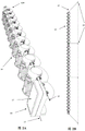
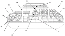
fig. 1 shows a perspective view of an apparatus for farming oysters, deployed on a line, according to one embodiment of the invention;
fig. 2A shows a perspective view of a system for farming oysters, according to one embodiment of the invention, comprising a plurality of the apparatus for farming oysters of fig. 1 deployed in line along a extension line;
FIG. 2B shows a side view of a running line along which three sets of ten of the oyster farming apparatuses of FIG. 1 and their corresponding female floats are arranged;
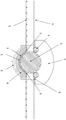
FIG. 3A shows a carousel for use with an apparatus for growing oysters according to one embodiment of the invention;
FIG. 3B shows the carousel of FIG. 3A with the lid of one of its oyster cages in an open configuration;
FIG. 4 shows an exploded view of the apparatus of FIG. 1 on a tether;
FIG. 5 shows a perspective view of the opposite side of the device of FIG. 1 on a running line;
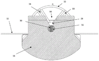
FIG. 6 shows the apparatus of FIG. 1 labeled in FIG. 56A cross-sectional view through the driver side of the device at section (a);
FIG. 7 shows the apparatus of FIG. 1 labeled in FIG. 57A cross-sectional view through the driver side of the device at section (a);
fig. 8A shows a perspective view of a female float for actuating movement of one or more oyster cages of one or more devices for raising oysters according to an embodiment of the invention;
FIG. 8B shows the female float of FIG. 8A labeled as FIG. 8A8BA cross-sectional view taken along a midpoint of the float at section (a);
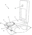
FIG. 9 shows an end view of a vessel for retrieving and deploying a turntable of the apparatus of FIG. 1;
FIG. 10 illustrates a side perspective view of the vessel of FIG. 9; and is
FIG. 11 illustrates an upper perspective view of the vessel of FIG. 9.
Detailed Description
As noted above, the present invention relates to improved oyster farming apparatuses, methods, and systems. The invention is particularly suitable for breeding intertidal oysters (such as Sydney crassostrea), but may be used to breed any kind of oyster that is capable of surviving on water for a period of time.
The invention will be described below in the context of breeding Sydney rock oysters. However, one skilled in the art would be able to adapt the teachings contained herein to the cultivation of other intertidal oysters, and indeed, in some cases, even sub-tidal oysters (i.e., those that can survive on water for some period of time).
Modern oyster farming involves multiple stages. Briefly, oyster eggs are typically grown in nursery sites until reaching a size of about 3.1mm and are then ready for transfer to the estuary environment. The oyster eggs are kept in the oyster nursery cages until reaching a size of about 15mm, and grading is performed approximately every 6 weeks (using a "wet grader" system to avoid damage to the oyster shells) to ensure proper growth. The oyster jubes are then transferred to a grow-out cage where they grow from about 15mm to about 90mm to 100mm marketable size. The sidney crassostrea grows to marketable size in 3 to 3 and a half years and it is during the period of time that the present invention can be utilized. This is the most important stage of oyster growth, and the time, space and labor traditionally involved makes it the most expensive part of the oyster growth process.
Intertidal oysters naturally grow on surfaces that experience a range of tidal heights, which means that they continually move in and out of the water during growth. This constant immersion in and emergence from water promotes their growth. The present invention advantageously mimics this natural event and may even have the potential to improve oyster growth rate.
The apparatus of the present invention comprises: a float; at least one oyster container configured to hold oysters and carried on a float; and a drive operable to periodically move each of the at least one oyster container between an underwater position and an above-water position.
The system of the present invention comprises: a plurality of devices for breeding oysters; a running string on which each of a plurality of devices for breeding oysters is or may be arranged; and a female float disposed or disposable on the extension cord and including a motor operable to actuate a driver of each of the plurality of apparatus for growing oysters. Each apparatus comprises: a float; at least one oyster container configured to hold oysters and carried on a float; and a drive operable to periodically move each of the at least one oyster container between an underwater position and an above-water position.
The apparatus of the invention comprises at least one oyster container carried on or by a float. The one or more oyster containers may take any form and have any shape suitable for use in the manner described herein. In some embodiments, the oyster container may be provided in the form of an oyster cage, which is already common in the industry.
In some embodiments, the container may be a rectangular prism, such a container facilitating filling and emptying of oysters therefrom. The one or more containers may alternatively have a cylindrical or triangular pyramidal shape, for example, if such a shape may provide advantages (e.g., more efficient weight distribution or greater load bearing capacity). In embodiments where the apparatus comprises two or more vessels, each vessel may be the same as or different from the other vessels.
The container may be made of any suitable material. The container should be corrosion resistant and should be strong enough to handle the expected wear of long term submersion in water, exposure to ultraviolet radiation, repeated handling (e.g. during oyster classification, as will be described below), and the constant movement of tides. Typically, the container will be made of a plastic material, preferably a food grade plastic material, in order to reduce any risk of contamination of the oysters or the estuary environment in which they grow. However, in some cases, a suitably durable and corrosion resistant metal may be used.
The side walls of the container (usually all surfaces) typically also have a plurality of apertures to allow water to flow through the container so that the nutrients in the water are readily consumed by the oysters held therein. The size and pattern of these openings may be adjusted based on factors such as the size of the oysters to be contained therein and the nutritional content of the water. Generally, larger openings are better, but they should (of course) not be so large that younger (and therefore smaller) oysters may fall out. In addition, allowing water to flow through the receptacles in this manner can help reduce drag of the receptacles in the water, which can be important when a large number of receptacles are on the same line and are repeatedly subjected to tidal currents in opposite directions.
Although the apparatus may comprise only one container containing oysters, more typically a plurality of containers will be carried on the float, at least for efficiency reasons. The relative positioning of two or more oyster containers (relative to each other and to other components of the apparatus) may, for example, be adjusted so that the oysters are evenly distributed in the water column so that the weight of the containers cancel each other out so that the float remains substantially level in the water regardless of the relative position of the oyster containers and/or so that the oyster containers require less energy to move.
For example, oysters at different growth stages may be stored in different containers so that each facility can supply the marketable oysters relatively continuously.
In some embodiments (described in further detail below), a plurality of oyster containers can be disposed in a rotatable cylinder, also referred to herein as a carousel. Oyster containers may be positioned on the rotatable cylinder in any configuration, but positioning the containers radially in the rotatable cylinder may distribute their weight more evenly throughout the cylinder and may therefore be preferred. As will be described below, in some embodiments, the oyster container may define spokes of the cylinder whose weight is substantially evenly distributed around the hub of the cylinder.
In such relatively evenly balanced embodiments, a driver (described in more detail below) is operable to rotate the rotatable cylinder with less energy than would otherwise be required if the oyster container were not so evenly balanced. The drive may, for example, be operatively coupled to the axle of the rotatable cylinder, in which case rotating the axle of the cylinder moves the oyster container between its submerged and above-water positions.
In some alternative embodiments, other mechanisms may be used to move the containers containing oysters between their underwater and above-water positions. For example, a seesaw, conveyor or endless loop type mechanism would be effective.
The oysters need to be graded periodically to ensure that they grow at an appropriate rate, necessitating their transportation to a facility located on land. One way in which the oyster container may be retrieved is to provide a turntable (or any other form in which one or more oyster containers are provided) having an upper attachment point for lifting off a float and out of the water. The upper attachment point may be located on any upper portion of the carousel (one or more containers) provided it is easily accessible. Typically, the upper attachment point includes laterally spaced apertures such that the float is substantially evenly balanced when lifted (e.g., as described below). The upper attachment point may have any suitable form and may, for example, be an aperture adapted to receive a hook therein.
Oyster containers typically include a closure that can be opened to gain access to the interior of the container (and thus to any oysters contained therein). The container may, for example, include an end that can be opened (e.g., by pivoting about an edge) to access the oysters contained within the container (or to add oysters to an empty cage).
In some embodiments, the oyster container may include one or more dividers that define separate oyster holding portions of the container. By distributing the oysters in a plurality of smaller containers, the oysters can be more evenly spread out, thereby enabling better access to nutrients in the water flowing through the cage. As will be appreciated, the growth rate of oysters will increase as they acquire nutrients in the water. Oyster containers that are smaller in size than conventional oyster cages (which may be very large in some cases, but are not typically used for intertidal oyster farming) may also be easier to handle and empty, and so on.
Traditionally, oysters are kept in large cages while growing. Although such cages are satisfactory (and have been used for many years in the australian oyster industry), the inventors have recognised that they suffer from a number of attendant problems, many of which can be overcome using the oyster container according to the invention. Advantageously, providing containers containing oysters in the potentially smaller form described herein enables these containers to have a significantly smaller volume than conventional oyster cages, but assembling these containers together has a combined volume that can hold the same number (or more) of oysters.
The apparatus of the invention also includes a float which can carry one or more oyster containers. The float may be of any suitable form and shape provided that it floats and may carry one or more oyster holding containers in such a way that they can move between their above-water and under-water positions. In some embodiments, the float may, for example, have a substantially rectangular footprint, which is relatively easy to manufacture, is generally stable in water, and is capable of bridging the gap between two parallel lines. In some embodiments, the float may include rounded edges in order to reduce the risk of the float becoming stuck between the hulls of a floating vessel, as described below.
The float must float to some extent above the water surface, thereby enabling the oyster holding container or containers carried thereon to move between its submerged and above-water positions. In some embodiments, the buoyancy of the float may be adjusted as necessary (e.g., by adding water or sand, etc. to a chamber in the float) to account for the different weights of oysters to be carried.
Ideally, the float may have a configuration which ensures that the oyster container does not approach the seabed, and is therefore still able to move, even at extremely low tides, particularly where the oysters are growing in relatively shallow water. Some prior art cultivation practices result in oysters spending a period of time in the mud on the seabed during low tide, which provides less than ideal growth conditions.
As noted above, it is necessary to periodically collect one or more containers containing oysters in order to grade the oysters, and to collect them again when they are ready to be marketed. While such collection may involve collecting the entire plant, transporting it to a staging facility, and then redeploying the plant (i.e., using the just-staged oysters), it may be more efficient if only a minimum number of components of the plant need to be collected. Thus, in some embodiments, at least one oyster container can be separated from the float (e.g., by lifting directly off the float). If there is more than one oyster container, each container can be separated/lifted from the float separately, but efficiency may also be higher if all containers are separated/lifted from the float at the same time (e.g., as is the case with the rotatable cylinder/carousel described herein).
The float may, for example, comprise opposing sidewalls having channels configured to receive therein complementary portions of one or more oyster containers, or in some suitable embodiments, complementary portions of a component (e.g., a turntable described herein) in which the oyster containers are provided. Such a channel may be tapered so that at least one oyster container (or the like) is guided into position while being lowered onto the float, which makes the operation easier to perform even in windy and wave conditions. For example, in some embodiments in which an oyster container is disposed in a carousel as described herein, the channels may be configured to receive opposite ends of an axle of the carousel.
The float may also include an attachment for attaching the float to one or more running lines. Although the float may be attached to only one elongate line, more typically it will be attached between two (usually parallel) elongate lines in order to be more securely positioned relative to any adjacent floats/devices. In some embodiments where the float spans between two parallel longlines, the opposite edge of the float may include a longline attachment of any suitable form. For example, in one embodiment, the tether attachment (or at least one of the tether attachments) may be provided in the form of a channel in the side of the float and into which the tether may be received. A latch or the like may be provided to securely retain the length of rope within the channel. For example, in some embodiments, the entrance to the channel may be closed by a user operable (e.g., movable) latch. The latch may, for example, pivot (or may otherwise move, for example, by sliding or twisting) between an open channel (i.e., unobstructed channel) configuration and a closed channel (i.e., obstructed channel) configuration. The latch may, for example, include a handle that may be grasped by a user (e.g., a gloved user).
In some embodiments, the channel may also include a recess complementary in shape to the bulbous portion of the tether (e.g., provided in the form of a knot in the tether, as described below). Once the bulbous portion is received in the recess, the float should not be able to slide along the tether. Thus, the float or floats cannot escape from the elongate line or lines because at least one of the elongate lines is located in and retained by the channel, and the location of the bulbous portion in the recess substantially prevents the float(s) from moving along the length of the elongate line.
Advantageously, in this embodiment, the floats may thus keep the longlines separated by a consistent distance, wherein the floats may be positioned relatively close together because they cannot be easily twisted relative to the longlines (e.g., as compared to prior art systems where floats are typically attached to a single longline and if positioned too close together, tangling may occur). In addition, because the relative movement between the float and the extension cord of the present invention tends to be greatly reduced (e.g., as compared to prior art systems), wear on the float (and other components of the oyster farm) due to constant water movement may be reduced.
It is possible to purchase a length of rope with knots pre-tied at precise intervals therealong to provide a length of rope adapted to receive the float of the present invention at predetermined spaced apart intervals. The distance between the knot/float will depend on factors such as the size of the float (and any container carried thereon) and the strength of the water flow perpendicular to the running line.
The float may be formed of any suitable material. Typically, the float is formed of a buoyant plastics material having a high degree of resistance to ultraviolet light. In some embodiments where any of the components of the float are metal, then these components would need to be made of a corrosion resistant metal (such as ship grade stainless steel) and would typically be integrally formed with the float (e.g., during the molding process).
The apparatus of the invention further comprises a drive operable to periodically move each of the at least one oyster container between an underwater position and an above-water position. The drive may be operated using any mechanism that can be used with the present invention and that moves one or more vessels between their submerged and above water positions.
The drive may be operable to move the one or more containers at any suitable rate. The drive may move the one or more vessels between its/their submerged and above water positions, for example at a rate that mimics an intertidal environment. Alternatively, the drive may be operable to move the container between its underwater position and the above-water position each day (or according to another fixed time period). As noted above, the inventors contemplate that optimal growth rates of oysters (e.g., for a particular species of oyster at a particular location) can be achieved by adjusting the length of time the oysters spend above and below water. Thus, faster or slower rates of movement may provide some advantages in certain circumstances. The inventors also contemplate that seasonal variations may also be taken into account by altering the rate at which one or more vessels are moved between an underwater position and an above-water position.
In some embodiments, the drive itself may comprise a motor for driving the containers between the submerged position and the above-water position of one or more containers. However, such embodiments may not be particularly effective, and this is particularly true in some embodiments of the invention described in more detail below that involve multiple devices arranged along a running line. Thus, more typically, the driver of each device may be actuated by a remote motor (which will be described in further detail below).
In such embodiments, the driver may include a driven member that may rotate upon actuation of the remote motor. Such driven members may be driven using any suitable mechanism, including via an endless rope, with a remote motor causing linear movement of the endless rope which is used to rotate the driven member of the (or each) driver.
The driven member may have any suitable form. Typically, the driven member is a driven pulley. In one form, the driven member/pulley may include an endless rope receiving channel, whereby movement of the endless rope in the channel causes the driven member/pulley to rotate. In some embodiments, the endless rope-receiving channel may be tapered inwardly and/or include rope gripping teeth or ribs to provide the necessary friction between the rope and the channel. Alternatively (or in addition), the endless rope may have spaced apart knots that are receivable within complementary recesses in the endless rope receiving channel.
For efficiency considerations, the plurality of devices described herein will typically be arranged in line along the length of the tether, thereby defining part of the system of the present invention. As indicated above, the system of the present invention comprises: a plurality of devices for breeding oysters; a running string on which each of a plurality of devices for culturing oysters is arranged; and a female float disposed on the extension cord and including a motor operable to actuate a driver of each of the plurality of apparatus for farming oysters.
As described herein, the float of this patent may take any form compatible with its use in the present invention. Typically, the female float will have a footprint (or at least a certain width) and the depth of the float is similar to the depth of the device with which it shares a tether. The parent float may also include a solar panel and battery for powering the motor, as well as other components, such as measurement devices for measuring parameters of the water associated with the growth of the oysters (e.g., its temperature, salinity, dissolved organic content, etc.), and transmission devices for transmitting this data to a remote location. The female float may also have a camera for remote viewing of the line and an alarm that is triggered when tampering is done inappropriately or other detected damage occurs (e.g., damage from a storm).
The motor on the female float may take any suitable form. In some embodiments, the motor may include drive and driven sprockets, the gear ratio of which is adjustable to enable the motor (with a particular power output) to actuate the drive so that they drive the movement of one or more containers at an appropriate rate. Indeed, in some embodiments, an intermediate gear transmission may be required for the drive system to function. Typically, any such gearing will be located in the female float and associated with the motor, but it could alternatively (or in addition) be part of the drive of each device.
The system typically also includes a drive belt, endless rope, or other corrosion resistant drive chain that can be driven by the motor of the female buoy to actuate the driver for each of the apparatus for growing oysters. In such embodiments, the driven sprocket of the female buoy can include an endless rope (or the like) receiving channel. Thus, actuation of the motor rotates the driven sprocket, thereby advancing the endless rope.
The system may include any number of female floats depending primarily on the number of devices on the tether, the apparent weight of the oysters in each device, and the power output of the motor. For example, in some embodiments, the system may include one mother buoy for every 5, 6, 7, 8, 9, 10, 11, 12, 13, 14, or 15 devices used to grow oysters.
The female float may be positioned on the tether in any configuration relative to its accompanying equipment. For example, in some embodiments, the female float may be disposed at one side of its companion device on the tether. Alternatively, the female float may be disposed on the tether in the middle (e.g., in the middle portion) of its accompanying device.
In some embodiments, the system may include an override device, wherein the motor may be disengaged from the endless rope (or the like) and the endless rope is manually advanced. This may be useful in embodiments where a particular cage configuration is required for a particular purpose, such as when a turntable, which will be described in further detail below, is to be removed from the float. In such embodiments, a winch or the like may be provided to manually advance the endless rope.
As noted above, the present invention also provides a vessel (e.g., a work platform, such as the work platform described in further detail below) for deploying and retrieving one or more oyster containers carried on the float of the apparatus or system of the present invention. The vessel includes spaced apart hulls configured for spanning the facility, the deck, and a centrally located access opening through which at least one oyster container carried on the float is accessible from the deck.
As will become apparent from the discussion below, the vessel of the present invention may provide a number of advantages over vessels traditionally used for oyster farming. In fact, such vessels are usually simple aluminium punts from which the user must physically work (which is detrimental to the health of the user and also risks the user falling off the vessel). The vessel of the invention makes it easier to work the oysters more regularly and by doing so, the growth time of the oysters can be shortened by many months.
In some embodiments, the vessel may further comprise a lift operable to lift the one or more oyster containers off the float and onto the vessel. The elevator may be any device capable of lifting an oyster container, such as the turntable described herein, which may weigh several hundred kilograms, especially when they are initially withdrawn from the water.
In some embodiments, the vessel may also include a gantry for maneuvering one or more oyster containers above deck (i.e., once lifted off the buoy), for example to move the one or more containers from directly above the inlet to a storage position (described below).
In the vessel, the oyster container can be centrally located in the vessel by being lifted from and lowered onto the float (i.e., able to be lifted out of the water and able to be lowered into the water). Thus, the lift does not need to lift a relatively heavy mass from the side of the vessel, as many currently used vessels do, but can lift it from a central location so as not to potentially unbalance the vessel. In addition, the user does not have to bend over the side of the vessel in order to retrieve the oyster container from the water.
Indeed, even in the case of existing vessels comprising some sort of lifting device (such as a crane), the weight that can be lifted may be limited, since the crane must extend on one side of the vessel, and the subsequent eccentric lifting action may cause a risk of overturning. In addition, even when the oyster cages are loaded onto the vessel, the oyster cages must be stored at specific locations on the vessel in order to maintain their level. For this reason, some vessels do not store the collected oyster cages at any time, but immediately transfer them to another vessel and bring them ashore for further processing. As will be appreciated, while existing vessels can be made to operate in oyster farming applications, they are in fact incompatible with effective farming practices and often require multiple vessels and/or travel between the oyster farm and processing facilities located on land multiple times.
In some embodiments, the vessel may further comprise shelves on which collected oyster containers may be placed (i.e., using the crane and gantry described above).
In some embodiments, the vessel may include a first portion for containing recently collected oyster containers (i.e., containing oysters that are ready for classification or marketing) and a second portion for containing oyster containers that are ready for deployment (i.e., containing recently classified oysters). Such a configuration would even further improve the efficiency of an oyster farm, where the graded oysters are placed back into the water as soon as possible after grading, while the next batch of oysters is collected for grading. Thus, the efficiency of oyster work can be higher than is possible in more traditional oyster farms.
In some embodiments, the buoyancy of the hull proximal to the first portion and the buoyancy of the hull proximal to the second portion may be independently adjusted in response to the distribution of weight on the vessel. This adjustable buoyancy works in response to changes in the weight distribution on the vessel, although it may have a very large eccentric mass, in order to keep the vessel level. In some embodiments, the buoyancy of the first portion and the buoyancy of the second portion may be independently adjusted to maintain the upper surface of the vessel in a substantially horizontal configuration. That is, regardless of how many oyster containers/cages are stored on one of the sections than on the other section (and of course, within a reasonable range), their buoyancy can be independently adjusted to keep the vessel in balance. This may provide significant advantages to oyster breeders as will be described in further detail below.
Any suitable technique may be used to adjust the buoyancy of the first and second portions. For example, in some embodiments, the one or more hulls at the first portion may include one or more first reservoirs, and the one or more hulls at the second portion may include one or more second reservoirs, the one or more first and second reservoirs being adapted to receive and expel fluid (e.g., air or water) in response to weight distribution on the floating vessel. The bow and stern portions of the port and starboard hulls may, for example, be configured to define a suitable receptacle.
For example, in some embodiments, the vessel may further include one or more pumps in communication with the first and second reservoirs, the one or more pumps operable to pump water into and out of the first and second reservoirs (i.e., in response to weight distribution on the vessel). In some embodiments, the first reservoir may have a first pump and the second reservoir may have a second pump. Water can be stored on the vessel or simply pumped in from an inlet below the vessel (keeping in mind that this will be brackish and so the pump must be adapted to work in salt water).
Any suitable system may be used to monitor the angle of the upper surface (i.e., deck) of the vessel (and its various sections) and operate one or more pumps (or the like) so that the upper surface remains substantially horizontal (or has some other desired configuration). It is envisaged that a plurality of sensors are located around various sections of the vessel, with data obtained from the sensors being fed into a CPU which runs a program capable of sending instructions to adjust the buoyancy of the various sections independently (e.g. by actuating one or more pumps).
The vessel may be propelled through the water using any suitable propulsion mechanism or system. In some embodiments, the vessel may further comprise a plurality of outlets from which water may be discharged to propel the floating platform in the water. Such outlets are commonly referred to in the industry as water jet thrusters and, when oriented facing sideways, as side thrusters. Providing such thrusters facing all directions from a working vessel enables the vessel to be moved in any direction, which may be particularly useful when maneuvering the vessel relative to the longline (especially when there are also factors countering it such as wind, surface waves and tidal currents). Although propellers may also be used to propel the work platform, the use of propellers is generally avoided (particularly when maneuvering near an oyster rental lot) because the propeller blades may damage or be snagged by the infrastructure (e.g., oyster cages or extension ropes) on the oyster rental lot.
As noted above, in one form of commercial operation of an oyster farm utilizing the teachings of the present invention, it is contemplated that individual investors may own oysters held in specific cages, carousels, or even extended ropes. For example, oyster juveniles (e.g., oysters having a size of about 15mm or about 50 mm) may be purchased at a relatively low price by an investor who then pays to foster the oysters in the components of the invention (i.e., depending on the number of oysters purchased) until the oysters are ready to market.
For example, in some embodiments, customers may purchase "rental lot assignments" that enable them to exclusively enjoy the feeding infrastructure maintained and managed by oyster farms. The customer is then allocated the production of the infrastructure at a predetermined fixed price per oyster and delivered monthly to the customer. For example, rental allocation of sydney oysters may involve purchasing exclusive use of a carousel (described below) for holding sydney oyster larvae. Each of these discs can produce about 1600 sydney oysters a year. Sydney oysters are an ideal choice for transporting fresh goods because they can survive in water for about three weeks each time.
Some specific embodiments of the present invention will now be described with reference to the accompanying drawings.
Referring first to fig. 1, an apparatus in the form of an apparatus 10 for growing oysters is shown. The device 10 is positioned between the running ropes 12 and is held in a fixed position on the running ropes in the manner described below. As can be seen in fig. 2B, each of the lines 12 is anchored to the seabed at an anchor 14, with the lines 12, 12 being maintained in a substantially parallel configuration over their length. For clarity the water surface is not shown, but the lines 12, 12 are located substantially at the level of the water surface. Those parts of the apparatus 10 which are lower than the lines 12, 12 will therefore be underwater.
The apparatus 10 includes a float 16 and an oyster holding cage (shown generally at 18) carried on a rotatable cylinder shown in the form of a turntable 20. The apparatus 10 also includes a drive operable to rotate the turntable 20 (and thus move each cage 18 between an underwater position and an above-water position, as will be described below), and is shown in the form of a driven pulley 22. As will be described in further detail below, the driven pulley 22 receives the knotted cord 24 therein in a manner such that movement of the knotted cord 24 relative to the driven pulley 22 causes the dial 20 to rotate.
Referring now to fig. 2A and 2B, a system according to one embodiment of the present invention is shown. The system shown in fig. 2A comprises ten devices 10 and a female float in the form of a drive float 26, all of which are attached to the running lines 12, 12 at spaced intervals in the manner described below. The uppermost surface 27 of the drive float 26 may include a solar panel (not shown) that can generate electricity to power its motor (described below) or to recharge a battery (not shown) that powers the motor. The system shown in figure 2B comprises three sets of apparatus 10 of figure 2A and an actuating buoy 26 and in which the lines 12, 12 (only one line can be seen) are anchored to the seabed by a plurality of spaced apart anchors 14. The knotted string 24 (see fig. 2A, and described in further detail below) extends in a continuous loop from the driver float 26 to the device 10A furthest from the driver float 26.
Referring now to fig. 3A and 3B, the turntable 20 is shown in greater detail and is shown separated from the other components of the apparatus 10. The turntable 20 has an axle 28 about which it can rotate on the float 16 (as described below). The opposite ends of the axle 28 include annular rims 29, 29 (one annular rim 29 is also visible in fig. 1) that can be used to properly position the turntable 20 relative to the float 16 in a manner described below. One of the ends of the axle 28 includes a drive tab 30 that cooperates with the driven pulley 22 to rotate the turntable 20 in a manner described below. The other end of the axle (not shown) is circular in cross-section, which facilitates rotation of the dial 20 within the float 16.
The turntable 20 has circular rims 32, 32 at either end thereof, each rim 32 being supported by and joined to the hub 28 via five spokes (shown generally at 34). The rims 32, 32 of the turntable 20 are also stabilized by a number of cross bars (shown generally as cross bar 36) intermediate the spokes 34. The uppermost cross-bar 36 (when the turntable 20 is in its loading/unloading position, as will be described below) has spaced apart apertures 38, 38 for receiving fasteners therein for lifting the turntable 20 off of the float 16 (as will be described below). The apertures 38 are shown in fig. 3A and 3B on the interior of the crossbar 36, but may also be provided in protrusions that protrude upwardly from the crossbar (e.g., as shown in fig. 1).
The carousel 20 includes five oyster holding cages 18, each positioned between a respective spoke 34, 34. The cage 18 may be permanently fixed to the spokes 34, 34 or may be released from the spokes (e.g., by sliding) depending on the preference for loading or unloading oysters into or out of the cage 18. In the embodiment shown, the cage 18 is permanently secured to the spokes 34, 34. The cage 18 includes a lid 40 that is pivotable between an open position (i.e., as shown in fig. 3B) and a closed position (i.e., as shown in fig. 3A). When in the open position and the configuration of the carousel 20 shown in fig. 3B, any oysters within the cage 18 will fall out and into a suitably positioned oyster collection facility, such as a sorting facility to which the oysters are transferred. Freshly graded oysters (i.e., ready for deployment back into the water) can be easily delivered into an empty cage 18 by rotating the carousel 20 with the lid 40 open so that the cage 18 faces upward and then pouring an appropriate amount of oysters into the cage. Once the lid 40 has been closed, the oysters are securely held therein. Suitable latching means (not shown) will be provided to ensure that the cover 40 is not accidentally opened during rotation in water.
The cage 18 also includes a number of dividers (shown generally at 42) that divide the cage into a plurality of smaller sections. These dividers 42 prevent all oysters contained within the cage 18 from clumping together, which could restrict access of the oysters to nutrients in the water column.
It is contemplated that the cages 18 will be formed of food grade plastics that are sufficiently durable, but they may be formed of other plastics or corrosion resistant metals. Each cage 18 is adapted to receive a quantity of oysters that are appropriate for the size of the cage, but not so much that overcrowding, which could potentially impede oyster growth by limiting oyster access to nutrients in the water, may occur. For example, in one particular embodiment of the invention in which Sydney crassostrea oysters are growing, the cage may be 150mm wide, 400mm high and 800mm long. A turntable 20 having five cages 18 of this size would be expected to operate effectively to produce about 1600 sydney oysters per year.
The openings in the cage 18 must be of a size that allows water to flow freely through the cage, but not so large that oysters may fall out of the cage. The smallest size oysters that can be used in the apparatus 10 will be oyster juveniles about 15mm in size. Therefore, some cages 18 must have openings less than 15mm in order to accommodate such oysters. However, if the cage is used only to hold larger oysters (e.g., 50mm or larger), larger opening sizes would be preferred. Generally, as large an opening size as possible will be preferred as this enables water (which is nutrient rich) to flow through the cage 18 with less resistance. In some embodiments, the turntable 20 may include a cage 18 having a variety of opening sizes. Indeed, in some farming operations, it may be desirable for the carousel 20 to hold oysters of different sizes, such that each time the carousel 20 is collected (e.g., once every 4 to 6 weeks, as described below), oysters from one of the cages 18 are ready for harvest, with oysters in other cages 18, etc., being staged, placed back in their cages, and returned to the apparatus 10. The empty cage 18 may be filled with new oyster juveniles.
The number of oysters that each cage 18 can hold will vary depending on the size of the oysters, but care should be taken not to overcrowd the cages as this may result in a suboptimal growth rate. For example, in one farming operation, the same oysters may be left in the same cage until ready for marketing. In such cases, since about 200 fully mature sydney oysters will fit into a cage of the above dimensions, the same number of oyster juveniles (e.g. having a size of about 50 mm) may be added initially to the cage and some additional oysters may be added at that time to take into account inventory losses that may occur during the growing period. For example, about 220 Sydney oysters, having a size of about 50mm, may be initially added to the cage 18, with the hope that 200 or more fully mature oysters will be produced after about 5 fractionation cycles. For example, in another farming operation, oyster juveniles having a size of 15mm may be raised in cages until they reach 50mm and transferred elsewhere, or until they reach a size of market. The regular grading of such oysters will eliminate dead oysters and underproplased oysters, thus providing the best possible growth conditions for the remaining oysters.
As will be appreciated, the size of the cage 18 and turntable 20 will also need to conform to the operating parameters (primarily size and weight) of the associated work platform when used in the oyster cultivation method disclosed herein.
Referring now to fig. 4 to 7, it can be seen that the outermost side of the float 16 includes lateral channels 44, 44 for receiving the lines 12, 12 therein. Since the channels 44 are identical in the embodiment shown, only one will be described in detail here. The passage 44 extends the length of the float 16 and includes a centrally located recess 46 shaped to receive therein a bulbous portion (provided in the form of a knot 48 in this embodiment) on the tether 12. The recess 46 may have any shape as long as it can securely receive and retain the knot 48 therein. Once the knot 48 is received within the recess 46 (and the tether 12 is received within the passage 44), the possibility of lateral and longitudinal movement of the float 16 relative to the tether 12 is very limited. Latches 50, 50 may be provided to securely retain the length of rope 12 within the channel 44.
A plurality of knots 48 (not shown) are provided at spaced intervals on one or both of the lines 12, 12 to maintain each float 16 (and thus each device 10) at a particular and predetermined location on the lines 12, 12 (i.e., as shown in fig. 2A and 2B, in which case the devices 10 are arranged in line along the lines so that they are in close proximity to each other, but do not touch each other). In this manner, the apparatus 10 may be held on the running strings 12, 12 in a very precise configuration, which may help maintain the oyster cage 18 in an optimal orientation and make retrieval and replacement of the turntable 20 more efficient.
Referring back to fig. 4, the driven pulley 22 includes an annular channel 52 around its periphery into which the knotted cord 24 may be received. The channel 52 includes spaced apart recesses (shown generally at 54) in which the knots of the knotted cord 24 may be received and retained. The longitudinal movement of the knotted cord 24 thereby causes the driven pulley 22, and thus the turntable 20, to rotate (as described below). A second annular channel 55 is provided next to the channel 52, but the channel 55 has no recess and is simply present as a guide for the non-drive side of the knotted cord 24 in order to keep it out of the water and to keep it contained so that there is no risk of snagging during the farming operation.
The driven pulley 22 also includes a drive shaft 56 (see also fig. 6) that is rotatably received within an aperture 58 on the side of the float 16. Once the drive shaft 56 is within the aperture 58, the driven pulley 22 is in its working position within the apparatus 10, and after the knot of knotted cord 24 is positioned in the channel 52/recess 54, the driven member 22 must be locked in place. In this regard, a cover 60 is provided that has a shape complementary to the driven member 22 and, when properly positioned (see fig. 7), defines a guide channel 61 between the cover 60 and the driven pulley 22 such that the knotted cord 24 is securely retained within the channel 52/recess 54 and the second channel 55. As can be seen in fig. 4, the cover 60 includes protrusions 62, 62 configured to fit snugly in apertures 64, 64 provided on the sides of the float 16. Once so positioned, the cover 60 is securely held in place on the float 16 (e.g., using a plastic latch or the like (not shown), or due to a frictional fit between the protrusion 62 and the aperture 64), and the driven pulley 22 or knotted cord 24 cannot be disengaged from the device 10.
The float 16 also has slots 66, 68 in the interior of its side walls that are configured for receiving therein opposite ends of the axle 28 of the turntable. The slots 66 and 68 are wider at their mouths and then narrow towards their ends, in which case the axle 28 resides therein when in the use configuration. The slot 68 has a substantially circular lowermost portion in which the respective end of the axle 28 of the turntable 20 can reside and rotate. The slot 66 has a similar tapered shape, but, as can be seen in fig. 6, has a bulbous lowermost portion which is aligned with the bore 58 and is therefore configured for receiving the drive shaft 56 of the driven pulley 22 therein. As can also be seen in fig. 6, the drive shaft 56 is shaped to receive the drive tabs 30 of the dial 20 therein. Thus, when in the loading configuration (i.e., as shown in fig. 4 and 6), lowering the dial 20 into the float 16 causes the drive tab 30 to move to the bottom of the slot 66, whereupon it operably engages the drive shaft 56 (i.e., as shown in fig. 6). Once the dial 20 is rotated to the position shown in fig. 6, it cannot escape from the float 16. However, it may be desirable to include some sort of retention mechanism (not shown) whereby, once so loaded, the turntable 20 cannot be inadvertently lifted out of its operative position while rotating through the orientation shown in fig. 6.
Referring now to fig. 8A and 8B, the driver float 26 is shown in greater detail. The drive float 26 has a motor 72 operable to drive a drive sprocket 74. The drive sprocket 74 drives a (larger) driven sprocket 76 that includes an annular channel 78 around its periphery and into which the knotted cord 24 can be received. The channel 78 includes spaced apart recesses (shown generally as 80) into which the knots of the knotted cord 24 may be received and retained. In this manner, operation of the motor 72 causes the knotted cord 24 to advance linearly around the sprocket 76 and thus through the driven pulley 22 of each apparatus 10 in the system. As mentioned above, additional gearing (not shown) may be provided if additional mechanical advantage is required to rotate the turntable 20 in the system.
Fig. 8B shows the knotted rope 24 advancing through the passage defined between the driven sprocket 76 and the body of the drive float 26. The driven sprocket 76 has an axle 82 that is received in a recess 84 in the cover of the drive float 26.
In use, linear advancement of the knotted string 24 through the driven pulley 22 of each apparatus 10 in the system causes rotation of the drive shaft 56, and thus the dial 20 (i.e., via the coupling between the drive lugs 30 and the drive shaft 56). Rotation of the dial 20 causes the cage 18 to progressively move (i.e., rotate) about an axle 28 that is directly above the level on which the float 16 is floating. Thus, once the cage 18 is in a position below the axle 28, it will be under water. Similarly, once the cage 18 is in a position above the axle 28, it will be located on the water. In this manner, rotation of the turntable 20 causes each cage 18 to move periodically between a submerged position and an above-water position, thereby providing appropriate growing conditions for intertidal oysters (such as Sydney's oysters).
The rate of rotation of the turntable 20 can be temporarily changed by adjusting the speed of the motor 72 or more permanently changed by altering the relative sizes of the drive/driven sprockets and/or the size of the driven pulley 22. In some embodiments, the size of the driven pulley 22 may vary between devices 10 on a running line such that some turntables rotate faster or slower than others.
In some cases, it may be desirable to provide a manual override to disengage the oyster grower from the motor 72 in order to manually orient the turntable 20 (e.g., if the turntable is not in an orientation in which it can be lifted from the float when the grower is ready to lift the turntable from the float 16). A suitable switch (not shown) may be provided to disengage the motor 72, wherein a winch or the like (also not shown) is used to pull the driven sprocket 76 back in either direction, for example. A suitable coupling (e.g. a spindle, similar to that of a marine winch) for receiving the drive shaft of the winch may for example be provided in the axle 82 and be accessible without having to open the cover of the female float 26.
Figures 9 to 11 show a vessel for deploying and retrieving oyster cages from lines 12, 12 in the form of a carousel 20 according to one embodiment of the invention. Referring first to fig. 9, a vessel in the form of a work platform 100 is shown. The work platform 100 has two hulls 102, 102 defining a space 104 therebetween sized to receive the apparatus 10 therethrough. The work platform 100 has a deck 106 and an elevator in the form of a gantry 108 and winch 110 that uses a cable 111 (see fig. 10) to raise, lower and transfer the turntable 20 (e.g., via a hook or the like (not shown)). The central portion of the deck 106 has a deployment and retrieval access, shown in the form of an access 112 (see fig. 10), through which the turntable 20 can be lowered onto or lifted off a buoy 16 positioned within the space 104 between the hulls 102, 102.
The work platform 100 also has a plurality of storage rails 114 dispersed on the deck 106. The storage rails 114 include spaced apart rails configured for receiving the axles 28 of the carousels 20 thereon, wherein the annular rims 29, 29 of each carousel 20 securely retain the carousel 20 thereon. The deck 106 may be nominally divided into two sections, a first section 116 providing space for retrieved carousels 20 (i.e., containing oysters that are ready to be graded or are ready to be marketed), and a second section 118 providing space for ready-to-deploy carousels 20 (i.e., containing the most recently graded oysters).
As will be appreciated, if the number of turntables 20 on one of the sections 116, 118 is different from the number of turntables on the other of the sections 116, 118, the work platform 100 may become unbalanced in the water and its deck 106 will be angled (indicating a risk of tipping, and a potential hazard to the work environment). However, to address this issue, the work platform 100 may also include one or more pumps (not shown) operable to pump water into a reservoir (not shown) to be pumped into the respective portions at the opposite ends of the hulls 102, 102. The pump may be operated such that water is drawn from the surrounding environment and used for ballast in order to provide an even weight distribution on the work platform 100. In this way, the deck 106 of the work platform 100 may be maintained in a substantially horizontal configuration even when one of the sections 116, 118 is full of oysters (and therefore heavy), while the other section 116, 118 is empty (or alternatively, if one side of the work platform 110 is loaded heavier than the other).
The work platform 100 may be moved through the water by using water jets (not shown) of the type conventionally used in the art (propeller driven barges may also be used, but are not preferred due to the potential for damage and the significant risk of the propeller being caught). These sprinklers can be positioned at various locations (either facing in different directions or operable to face in different directions) above the work platform 100 and operated by a user.
In use, the turntable may stop rotating when the turntable 20 is in an orientation whereby they can be lifted off the float 16 (e.g., as shown in fig. 6). Alternatively, the turntable 20 may be manually rotated by the farmer to this orientation upon arrival at the farm. The farmer then orients the work platform 100 in line with the lines 12, 12 and then drives the work platform over the lines with the equipment 10, 10 etc received between the hulls 102, 102 as can be seen in figure 9. The devices 10, 10 etc. are spaced along the elongate lines 12, 12 such that many of them (for example 2 to 5, depending on their spacing) are located beneath the work platform 100 at any given time and therefore can be used to guide the work platform 100 along the elongate lines 12, 12 irrespective of the cross-flow that the work platform may encounter. The rounded end of the float 16 may help prevent the float 16 (and thus the device 10) from becoming trapped between the hulls 102, 102.
When the apparatus 10 is approximately centered under the entrance 112, the user will stop the barge 100 and attach hooks at the ends of the cables 111 to the upwardly oriented eyelets 38, 38 on the turntable 20. The winch 110 will be engaged so that the turntable 20 and its accompanying oyster-containing cage 18 are lifted off the float 16 and out of the water, through the inlet 112 and up to the elevated position (as shown in figure 10). In this raised position, the gantry 108 can be used to align the axles 28 of the turntable 20 with the rails (e.g., in section 116) of the appropriate storage rails 114, and then lower the turntable 20 onto the rails. The thus positioned turntable can then be removed from the entrance 112 by rotating it on the guide rails, a task that can be easily done manually. The turntable 20 containing the graded oysters ready to be placed back into the water can then be rolled from another portion (e.g., portion 118) of the work platform 100 into position, lifted with the winch 110, aligned with the inlet 112, and then lowered onto the float 16 (now empty) positioned below the inlet 112.
This replacement operation is repeated until all of the turntables 20 on the lines 12, 12 have been replaced, or until all of the turntables 20 originally carried by the work platform 100 have been placed back into the water. In this way, in a single operation, the oysters that need to be classified are removed from the water and the already classified oysters are placed back into the water. The efficiency savings that can be achieved by this approach are apparent. During all of these operations, one or more pumps pump water into or out of the respective portions of the hulls 102, 102 in order to keep the work platform 100 substantially level.
The work platform 100 will then be manoeuvred to a grading facility located on land, where the carousel 20 containing oysters for grading or marketing can be unloaded and processed accordingly.
As described herein, the present invention provides improved oyster farming equipment particularly suited for farming intertidal oysters, as well as systems comprising a plurality of such equipment on a longline and a floating platform for deploying and retrieving oyster cages (e.g., for grading). Some embodiments of the invention may have one or more of the advantages listed below as compared to prior art oyster farming installations and systems.
The apparatus and system of the present invention may be advantageous because:
● Intertidal oysters are grown in a controlled environment with optimal conditions that can help to accelerate their growth rate, thereby reducing the time it takes to grow to marketable sizes.
● Much less manual operations are required to maintain oysters (i.e., to periodically move them from above water to below water), with most of such work being performed automatically.
● The cages are modular in nature and thus typically smaller than many existing cages, but the carousel is able to hold the same number (or more) of oysters in a more evenly distributed manner so that they can access the nutrients in the water at all times, thereby enhancing their growth (i.e., where the oysters may bunch up at the bottom of a relatively large cage, and thus cannot easily access nutrients, if at all, as compared to existing cages).
● The cage is easily opened to empty its contents into a classifier or the like.
● The cage can be formed of food grade plastic, thus being free of corrosion problems, easy to clean, free of food contamination problems, and the like.
● The floats keep the cords apart by a precise and consistent distance along their entire length.
● The floats/devices can be positioned relatively close together because they do not twist relative to the tether.
● The float/device may help guide the floating platform along the tether.
● The turntable is apt to lift and lower away from the float, wherein the tapered channels of the float guide the axle towards the respective working position of these channels. Thus, the operator does not need to operate very precisely when returning the oysters to the water.
The floating platform of the present invention is advantageous because:
● It is possible to make it easier to work the oysters more regularly and, by doing so, shorten the growth time of the oysters.
● The work on oysters can be made easier due to features such as: automatically raising/lowering the oyster cage (which may be larger due to its modular nature), the turntable being able to slide along the rails (much easier/safer than moving the cage with force), easy transfer from the floating platform to the grading system (e.g. via complementary land-located rails), the user working out of the water surface and thus being able to work in deeper waters without having to physically explore from the ship/barge (less WHS problems).
● The buoyancy system functions to keep the floating platform level, although it may have a large eccentric mass.
● The graded oysters can be deployed and the unfractionated oysters can be collected at the same time, thereby saving a great deal of time.
Those skilled in the art to which the invention pertains will appreciate that many modifications can be made without departing from the spirit and scope of the invention. All such modifications are intended to fall within the scope of the appended claims.
It should also be understood that although the foregoing description refers to a particular sequence of method steps, apparatus and equipment for performing such methods with respect to particular applications, and the elements of construction thereof, such details are provided for illustrative purposes only and are not intended to limit the scope of the invention in any way.
In the following claims and in the preceding description of the invention, unless the context requires otherwise due to express language or necessary implication, the word "comprise" or variations such as "comprises" or "comprising" is used in an inclusive sense, i.e. to specify the presence of the stated features but not to preclude the presence or addition of further features in various embodiments of the invention.
Claims (26)
1. An apparatus for growing oysters, the apparatus comprising:
a float configured to float on a water surface and carrying a plurality of oyster containers configured to hold oysters, wherein each oyster container is movable between an underwater position and an above water position; and
a drive operable to periodically move each of the oyster containers between the underwater position and the above-water position.
2. The apparatus of claim 1, wherein a plurality of oyster containers are disposed in a rotatable cylinder, wherein the driver is operable to rotate the rotatable cylinder.
3. The apparatus of claim 2, wherein the oyster container is positioned radially in the rotatable cylinder.
4. The apparatus of claim 1, wherein the drive is actuated by a remote motor.
5. The apparatus of claim 4, wherein the driver comprises a driven pulley that is rotatable upon actuation of the remote motor.
6. The apparatus of claim 5, wherein the remote motor drives an endless rope and the driven pulley comprises an endless rope receiving channel.
7. The apparatus of claim 6, wherein the endless rope comprises spaced apart knots receivable within complementary recesses in the endless rope receiving channel.
8. The apparatus of claim 1, wherein the drive is operable to move each of the oyster containers between the underwater location and the above-water location at a rate that mimics an intertidal environment.
9. The apparatus of claim 1, wherein the plurality of oyster containers can be lifted off of the float and lowered onto the float.
10. The apparatus of claim 1, wherein the float comprises opposing sidewalls having channels configured to receive complementary portions of the plurality of oyster containers therein.
11. The apparatus of claim 1, wherein the float comprises an attachment for attaching the float to one or more running lines.
12. The apparatus of claim 1, wherein each oyster container comprises a lid that can be opened to access the interior of the oyster container.
13. The apparatus of claim 1, wherein each oyster container comprises one or more dividers that define separate oyster holding portions of the container.
14. A system for growing oysters, the system comprising:
a plurality of apparatuses for growing oysters, each apparatus comprising:
a float;
at least one oyster container configured to hold oysters and carried on the float; and
a drive operable to periodically move each of the at least one oyster container between an underwater position and an above-water position;
a running string on which each of the plurality of devices for culturing oysters is arranged; and
a female float disposed on the extension cord and including a motor operable to actuate the driver of each of the plurality of oyster farming apparatuses.
15. The system of claim 14, further comprising an endless rope that is drivable by the motor to actuate the driver of each of the plurality of apparatuses for farming oysters.
16. The system of claim 14, wherein the motor comprises a drive sprocket and a driven sprocket, the driven sprocket further comprising an endless rope receiving channel.
17. The system of claim 14, wherein the system comprises one female buoy for every ten devices used to grow oysters.
18. The system of claim 14, wherein each of the plurality of apparatuses for growing oysters is the apparatus of any one of claims 1 to 13.
19. A vessel for deploying and retrieving at least one of the oyster containers carried on the float of the apparatus of any one of claims 1 to 13 or carried on the float of the system of any one of claims 14 to 18, the vessel comprising:
spaced apart hulls configured for spanning the apparatus;
a deck; and
a centrally located inlet through which at least one of the oyster containers carried on the float is accessible from the deck.
20. The vessel of claim 19, further comprising a lift operable to lift the oyster container off the float and onto the vessel.
21. The vessel of claim 19, further comprising a gantry operable to maneuver the oyster container over the deck.
22. The vessel of claim 19, further comprising a shelf on which collected oyster containers can be placed.
23. The vessel of claim 19, wherein the vessel comprises a first portion for containing recently collected oyster containers and a second portion for containing oyster containers ready for deployment.
24. A turntable for use with an apparatus for growing oysters according to any of claims 1 to 13, the turntable comprising an axis about which a plurality of oyster containers are radially arranged.
25. The turntable of claim 24, wherein the plurality of oyster containers are arranged radially whereby their weight is distributed substantially evenly about the axis.
26. The turntable of claim 24 or 25, wherein one end of the axis comprises a member that is coupleable to the driver such that operation of the driver causes the turntable to rotate about the axis.
Applications Claiming Priority (3)
| Application Number | Priority Date | Filing Date | Title |
|---|---|---|---|
| AU2017901617 | 2017-05-03 | ||
| AU2017901617A AU2017901617A0 (en) | 2017-05-03 | Oyster farming apparatus and methods | |
| PCT/AU2018/050403 WO2018201191A1 (en) | 2017-05-03 | 2018-05-03 | Oyster farming apparatus, methods and systems |
Publications (2)
| Publication Number | Publication Date |
|---|---|
| CN110662420A CN110662420A (en) | 2020-01-07 |
| CN110662420B true CN110662420B (en) | 2022-10-28 |
Family
ID=64015698
Family Applications (1)
| Application Number | Title | Priority Date | Filing Date |
|---|---|---|---|
| CN201880034330.9A Active CN110662420B (en) | 2017-05-03 | 2018-05-03 | Oyster cultivation equipment, method and system |
Country Status (7)
| Country | Link |
|---|---|
| US (1) | US20200060242A1 (en) |
| EP (1) | EP3618612A4 (en) |
| CN (1) | CN110662420B (en) |
| AU (1) | AU2018262107A1 (en) |
| CA (1) | CA3061981A1 (en) |
| MA (1) | MA50754A (en) |
| WO (1) | WO2018201191A1 (en) |
Families Citing this family (4)
| Publication number | Priority date | Publication date | Assignee | Title |
|---|---|---|---|---|
| CN110150197A (en) * | 2019-04-25 | 2019-08-23 | 袁治平 | A kind of agricultural aquaculture device |
| CN111937821B (en) * | 2020-08-25 | 2022-04-01 | 中国水产科学研究院渔业机械仪器研究所 | Transverse-rope cultivated oyster harvesting device and method |
| US11696571B2 (en) * | 2020-12-15 | 2023-07-11 | Mint Machine Technologies, Inc. | Systems and methods for automated maturation of oysters |
| CN114365711B (en) * | 2022-01-24 | 2023-02-28 | 威海金牌生物科技有限公司 | Selenium-rich oyster cultivation method |
Family Cites Families (14)
| Publication number | Priority date | Publication date | Assignee | Title |
|---|---|---|---|---|
| US4704990A (en) * | 1985-01-30 | 1987-11-10 | Moxham Wayne R | Cultivating molluscs |
| FR2719446A1 (en) * | 1994-05-06 | 1995-11-10 | Le Clanche Paul | Rotating cage for cultivation of shellfish |
| GB9507347D0 (en) * | 1995-04-07 | 1995-05-31 | Graham Robert | Apparatus and method for cultivating molluscs |
| WO1997046086A1 (en) | 1996-06-05 | 1997-12-11 | Marlborough Mussel Co. Limited | Apparatus for use in aquaculture |
| NO318733B1 (en) * | 2002-10-25 | 2005-05-02 | Tormod Drengstig | Device at shellfish farms |
| NO320012B1 (en) * | 2003-02-28 | 2005-10-10 | Praktisk Teknologi As | System for disposal and storage of benthic organisms, in an aquatic environment and procedures for handling containers for storage of such organisms |
| CN101390506A (en) * | 2008-11-04 | 2009-03-25 | 林通 | Automatic collection ship of seashell products |
| US10932452B2 (en) * | 2010-04-07 | 2021-03-02 | Steven J. Leslie | Aquaculture assembly and method |
| US20110265730A1 (en) * | 2010-04-30 | 2011-11-03 | Jon David Farrington | Apparatus for the cultivation of molluscan shellfish and other marine species |
| US20130255585A1 (en) * | 2012-03-07 | 2013-10-03 | Steve HAMMAN | Aquaculture methods & systems |
| CN103496438A (en) * | 2013-04-17 | 2014-01-08 | 莆田科大生物科技开发有限公司 | Catamaran type motorized operating platform |
| AU2016200539A1 (en) * | 2016-01-29 | 2017-08-17 | Seapa Pty Ltd | Floatation device for an aquaculture basket |
| CN105454120B (en) * | 2016-01-30 | 2018-05-11 | 中国海洋大学 | A kind of cultural method and device of top grade oyster |
| WO2018027283A1 (en) * | 2016-08-12 | 2018-02-15 | Seapa Pty Ltd | Floatation device for an oyster basket |
-
2018
- 2018-05-03 EP EP18794417.8A patent/EP3618612A4/en active Pending
- 2018-05-03 MA MA050754A patent/MA50754A/en unknown
- 2018-05-03 CA CA3061981A patent/CA3061981A1/en active Pending
- 2018-05-03 WO PCT/AU2018/050403 patent/WO2018201191A1/en unknown
- 2018-05-03 CN CN201880034330.9A patent/CN110662420B/en active Active
- 2018-05-03 AU AU2018262107A patent/AU2018262107A1/en active Pending
- 2018-05-03 US US16/610,457 patent/US20200060242A1/en active Pending
Also Published As
| Publication number | Publication date |
|---|---|
| WO2018201191A1 (en) | 2018-11-08 |
| EP3618612A4 (en) | 2021-02-17 |
| US20200060242A1 (en) | 2020-02-27 |
| EP3618612A1 (en) | 2020-03-11 |
| CA3061981A1 (en) | 2018-11-08 |
| AU2018262107A1 (en) | 2019-12-19 |
| MA50754A (en) | 2020-03-11 |
| CN110662420A (en) | 2020-01-07 |
Similar Documents
| Publication | Publication Date | Title |
|---|---|---|
| CN110662420B (en) | Oyster cultivation equipment, method and system | |
| CN114403066B (en) | Oyster cultivation equipment and method | |
| US20220279764A1 (en) | System and method for modular aquaculture | |
| US20190159434A1 (en) | Device for Rearing Aquaculture Animals At Sea | |
| JP7105506B2 (en) | Shellfish farming equipment, systems and methods of use | |
| KR20140089463A (en) | Management device of long-line type cage for abalone and refloat method thereby | |
| US20230320331A1 (en) | Systems and methods for automated maturation of oysters | |
| CN110720414B (en) | Collection device is bred to marine mussel | |
| KR102640969B1 (en) | Cultured Oyster Automatic Harvesting System | |
| RU2353090C2 (en) | Method of ii stashevsky for pearl production and device for its realisation (versions) | |
| Sarni et al. | Project SOAK Submersible Oceanic Aquaculture of Kelp | |
| NZ750328B2 (en) | Shellfish growing apparatus, system and method of using same | |
| NZ750328A (en) | Shellfish growing apparatus, system and method of using same |
Legal Events
| Date | Code | Title | Description |
|---|---|---|---|
| PB01 | Publication | ||
| PB01 | Publication | ||
| SE01 | Entry into force of request for substantive examination | ||
| SE01 | Entry into force of request for substantive examination | ||
| GR01 | Patent grant | ||
| GR01 | Patent grant |