CN110649750A - Motor shock attenuation mount pad - Google Patents
Motor shock attenuation mount pad Download PDFInfo
- Publication number
- CN110649750A CN110649750A CN201911111379.2A CN201911111379A CN110649750A CN 110649750 A CN110649750 A CN 110649750A CN 201911111379 A CN201911111379 A CN 201911111379A CN 110649750 A CN110649750 A CN 110649750A
- Authority
- CN
- China
- Prior art keywords
- plate
- base
- arc
- bearing plate
- fixed
- Prior art date
- Legal status (The legal status is an assumption and is not a legal conclusion. Google has not performed a legal analysis and makes no representation as to the accuracy of the status listed.)
- Pending
Links
- 230000035939 shock Effects 0.000 title claims description 16
- 238000013016 damping Methods 0.000 claims abstract description 27
- 230000007246 mechanism Effects 0.000 claims abstract description 3
- 238000010521 absorption reaction Methods 0.000 claims description 10
- 230000003044 adaptive effect Effects 0.000 claims 1
- 230000000694 effects Effects 0.000 description 7
- 238000009434 installation Methods 0.000 description 6
- 238000000034 method Methods 0.000 description 5
- 230000009471 action Effects 0.000 description 4
- 230000006978 adaptation Effects 0.000 description 2
- 230000008569 process Effects 0.000 description 2
- 230000004075 alteration Effects 0.000 description 1
- 230000009286 beneficial effect Effects 0.000 description 1
- 238000010276 construction Methods 0.000 description 1
- 230000007547 defect Effects 0.000 description 1
- 230000007123 defense Effects 0.000 description 1
- 238000010586 diagram Methods 0.000 description 1
- 230000009977 dual effect Effects 0.000 description 1
- 230000004048 modification Effects 0.000 description 1
- 238000012986 modification Methods 0.000 description 1
- 239000012466 permeate Substances 0.000 description 1
- 238000006467 substitution reaction Methods 0.000 description 1
Images

Classifications
-
- H—ELECTRICITY
- H02—GENERATION; CONVERSION OR DISTRIBUTION OF ELECTRIC POWER
- H02K—DYNAMO-ELECTRIC MACHINES
- H02K5/00—Casings; Enclosures; Supports
- H02K5/24—Casings; Enclosures; Supports specially adapted for suppression or reduction of noise or vibrations
Abstract
The invention discloses a motor damping mounting seat which comprises a base and a damping device, wherein the base is arranged in a U shape, the damping device is accommodated in a notch of the base, the damping device comprises an arc-shaped bearing plate used for accommodating a motor, a square bearing plate is fixed at the bottom end of the arc-shaped bearing plate, an arc-shaped fixing plate is arranged above the arc-shaped bearing plate, a square fixing plate is fixed at the top end of the arc-shaped fixing plate, the square fixing plate and the square bearing plate are fixedly connected through a screw rod, a plurality of damping springs are fixed between the bottom end of the square bearing plate and the notch of the base, limiting plates are arranged at the front end and the rear end of the notch of the base, the inner side wall of each limiting plate is abutted against the side wall of the square bearing plate, and auxiliary damping mechanisms.
Description
Technical Field
The invention relates to the technical field of motor auxiliary devices, in particular to a motor damping mounting seat.
Background
An electric motor is a device that converts electrical energy into mechanical energy. The motor is used as an important component in a dragging system and plays a very important role in national economy, the use of the motor almost permeates all industries and is an important guarantee for normal operation of industry, agriculture, national defense construction and people's life, so that the normal operation of the motor is very important, the motor is often required to be provided with a mounting seat for protecting the motor when being mounted, the traditional mounting seat is of a rigid structure as a whole, the damping effect is poor or even has no damping effect, the motor can generate mechanical vibration when being mounted, the noise is high, and the service life of the motor is short.
Disclosure of Invention
Technical problem to be solved
Aiming at the defects of the prior art, the invention provides a shock absorption mounting seat for a motor, which solves the problems of short service life and high noise of the motor caused by poor shock absorption effect or even no shock absorption effect of the traditional mounting seat.
(II) technical scheme
In order to achieve the purpose, the invention is realized by the following technical scheme: the utility model provides a motor shock attenuation mount pad, includes base and damping device, the base is the setting of U type, damping device holds in the notch of locating the base, damping device is including being used for holding the arc bearing plate of establishing the motor, arc bearing plate bottom mounting has square bearing plate, arc bearing plate top is provided with arc fixed plate, the arc fixed plate top is fixed with square fixed plate, it is fixed to connect through the screw rod between square fixed plate and the square bearing plate, be fixed with a plurality of damping spring between the notch of square bearing plate bottom and base, both ends all are provided with the limiting plate around the notch of base, just the limiting plate inside wall is inconsistent with square bearing plate lateral wall, both ends all are provided with supplementary damper around the base.
Preferably, supplementary damper is including fixing the first locating plate in the limiting plate outside, first locating plate top is provided with the second locating plate of being connected with square fixed plate, second locating plate bottom surface center is fixed with the locating lever down, the locating lever bottom passes first locating plate and extends to first locating plate below, be provided with the spring on the locating lever, the spring top is connected with second locating plate bottom surface, and the spring bottom is fixed with first locating plate top surface.
Preferably, the base includes U type seat, all be provided with the installation lid on the U type seat both sides wall, all set up the half slot of looks adaptation on U type seat and the installation lid, it is fixed through bolted connection between installation lid and the U type seat.
Preferably, the U-shaped seat and the semicircular groove of the mounting cover are both provided with a first cushion pad.
Preferably, the arc-shaped bearing plate and the arc-shaped fixing plate are both provided with second cushion pads.
Preferably, the circle center of the arc-shaped bearing plate and the circle center of the semicircular groove are located on the same horizontal line.
Preferably, the notch is provided with a sliding groove corresponding to the limiting plate, and the left end and the right end of the limiting plate are clamped in the sliding groove.
(III) advantageous effects
The invention provides a shock-absorbing mounting seat for a motor. The method has the following beneficial effects: the invention absorbs the vibration through the dual functions of the damping spring and the auxiliary damping mechanism, has obvious damping effect and long service life of the motor, and reduces or even absorbs the noise through the first buffer cushion and the second buffer cushion.
Drawings
FIG. 1 is a schematic view of the position relationship between the mounting base and the damping device of the present invention;
FIG. 2 is a schematic structural view of a positional relationship between a mounting seat with a limiting plate and a damping device according to the present invention;
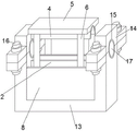
fig. 3 is a schematic structural diagram of the present invention.
In the figure, 1 notch, 2 arc-shaped bearing plates, 3 square bearing plates, 4 arc-shaped fixing plates, 5 square fixing plates, 6 screw rods, 7 damping springs, 8 limiting plates, 9 first positioning plates, 10 second positioning plates, 11 positioning rods, 12 springs, 13U-shaped seats, 14 mounting covers, 15 semicircular grooves, 16 bolts, 17 first cushion pads and 18 second cushion pads.
Detailed Description
The technical solutions in the embodiments of the present invention will be clearly and completely described below with reference to the drawings in the embodiments of the present invention, and it is obvious that the described embodiments are only a part of the embodiments of the present invention, and not all of the embodiments. All other embodiments, which can be derived by a person skilled in the art from the embodiments given herein without making any creative effort, shall fall within the protection scope of the present invention.
Referring to fig. 1-3, an embodiment of the present invention provides a technical solution: a shock absorption mounting seat of a motor comprises a base and a shock absorption device, wherein the base is arranged in a U shape, the shock absorption device is arranged in a notch 1 of the base, the shock absorption device comprises an arc-shaped bearing plate 2 used for accommodating the motor, a square bearing plate 3 is fixed at the bottom end of the arc-shaped bearing plate 2, an arc-shaped fixing plate 4 is arranged above the arc-shaped bearing plate 3, a square fixing plate 5 is fixed at the top end of the arc-shaped fixing plate 4, the motor is arranged in the arc-shaped bearing plate 3 and the arc-shaped fixing plate 4, the square fixing plate 5 and the square bearing plate 3 are fixedly connected through a screw rod 6, the space between the arc-shaped bearing plate 2 and the arc-shaped fixing plate 5 is suitable for the model size of the motor through an adjusting screw rod 6, a plurality of shock absorption springs 7 are fixed between the bottom end of the square bearing plate 3 and the, just 8 inside walls of limiting plate are inconsistent with 3 lateral walls of square bearing plate, have avoided rocking about square bearing plate 3, both ends all are provided with supplementary damper around the base.
Supplementary damper is including fixing the first locating plate 9 in the limiting plate 8 outside, first locating plate 9 top is provided with the second locating plate 10 of being connected with square fixed plate 5, second locating plate 10 bottom surface center is fixed with locating lever 11 down, first locating plate 9 is passed and extends to first locating plate 9 below to locating lever 11 bottom, be provided with spring 12 on the locating lever 11, the spring 12 top is connected with second locating plate 10 bottom surface, and the spring 12 bottom is fixed with first locating plate 9 top surface.
The base includes U type seat 13, all be provided with installation lid 14 on the wall of U type seat 13 both sides, all set up the half slot 15 of looks adaptation on U type seat 13 and the installation lid 14, it is fixed to connect through bolt 16 between installation lid 14 and the U type seat 13, and the axis of rotation of motor passes in the round hole that two half slots 15 formed.
And the arc-shaped bearing plate 2 and the arc-shaped fixing plate 4 are both provided with a second buffer cushion 18, and the second buffer cushion 18 is used for absorbing the vibration conducted in the motor.
The circle center of the arc-shaped bearing plate 2 and the circle center of the semicircular groove 15 are located on the same horizontal line, namely when the motor is placed on the arc-shaped bearing plate 2, the rotating shaft of the motor is just located in the semicircular groove 15 on the side wall of the corresponding side of the U-shaped seat 13.
The notch 1 is provided with a sliding groove corresponding to the limiting plate 8, the left end and the right end of the limiting plate 8 are clamped in the sliding groove, the limiting plate 8 can slide upwards from the sliding groove, and the limiting plate 8 can be detached.
The working principle of the invention is as follows: the motor is placed on the arc-shaped bearing plate 2, the rotating shaft of the motor penetrates through the semicircular groove 15 of the U-shaped seat 13, the mounting cover 14 is fixed on the U-shaped seat 13 through the bolt 16, the arc-shaped fixing plate 4 and the arc-shaped bearing plate 2 are fixed through the screw 6 after the motor is preliminarily fixed, the size of a space formed by the two is suitable for the size of the motor, vibration transmitted by the motor is absorbed by the first cushion pad 17 and the second cushion pad 18, when vibration exists outside or the vibration of the motor enables the motor to move with the arc-shaped bearing plate 2 and the arc-shaped fixing plate 4, the arc-shaped bearing plate 2 and the arc-shaped fixing plate 4 are fixed with the motor, so that the three integrally move upwards or downwards, when the motor moves upwards, the damping spring 7 and the spring 12 generate downwards pulling force on the motor, and the arc-shaped fixing plate 4, and when the damping spring 7 moves the, When the arc-shaped bearing plate 2 is integrally pulled to be below the initial state, the spring 12 generates upward thrust to the arc-shaped bearing plate, the damping effect is achieved through the combined action of the spring 12 and the damping spring 7, and when the arc-shaped bearing plate moves downwards, the force generated when the arc-shaped bearing plate moves upwards is opposite to the force generated when the arc-shaped bearing plate moves downwards.
It is noted that, herein, relational terms such as first and second, and the like may be used solely to distinguish one entity or action from another entity or action without necessarily requiring or implying any actual such relationship or order between such entities or actions. Also, the terms "comprises," "comprising," or any other variation thereof, are intended to cover a non-exclusive inclusion, such that a process, method, article, or apparatus that comprises a list of elements does not include only those elements but may include other elements not expressly listed or inherent to such process, method, article, or apparatus.
Although embodiments of the present invention have been shown and described, it will be appreciated by those skilled in the art that changes, modifications, substitutions and alterations can be made in these embodiments without departing from the principles and spirit of the invention, the scope of which is defined in the appended claims and their equivalents.
Claims (7)
1. The utility model provides a motor shock attenuation mount pad, includes base and damping device, its characterized in that, the base is the setting of U type, damping device holds in the notch of locating the base, damping device is including being used for holding the arc bearing plate of establishing the motor, arc bearing plate bottom mounting has square bearing plate, arc bearing plate top is provided with arc fixed plate, the arc fixed plate top is fixed with square fixed plate, it is fixed to connect through the screw rod between square fixed plate and the square bearing plate, be fixed with a plurality of damping spring between the notch of square bearing plate bottom and base, both ends all are provided with the limiting plate around the notch of base, just the inside wall is inconsistent with square bearing plate lateral wall, both ends all are provided with supplementary damper around the base.
2. The motor shock absorption mounting base according to claim 1, wherein the auxiliary shock absorption mechanism comprises a first positioning plate fixed outside the positioning plate, a second positioning plate connected with the square fixing plate is arranged above the first positioning plate, a positioning rod is fixed downwards in the center of the bottom surface of the second positioning plate, the bottom end of the positioning rod penetrates through the first positioning plate and extends to the lower portion of the first positioning plate, a spring is arranged on the positioning rod, the top end of the spring is connected with the bottom surface of the second positioning plate, and the bottom end of the spring is fixed with the top surface of the first positioning plate.
3. The shock-absorbing mounting base for the motor according to claim 1, wherein the base comprises a U-shaped base, mounting covers are arranged on two side walls of the U-shaped base, the U-shaped base and the mounting covers are respectively provided with adaptive semicircular grooves, and the mounting covers are fixedly connected with the U-shaped base through bolts.
4. A shock absorbing mounting for an electric motor as claimed in claim 3, wherein the first cushioning pad is located in the semicircular slot of each of the U-shaped base and the mounting cover.
5. The shock absorbing mount for electric motor of claim 1, wherein said arc-shaped bearing plate and said arc-shaped fixing plate are provided with second cushion pads.
6. The shock-absorbing mounting base for the motor as claimed in claim 1, wherein the center of the arc-shaped bearing plate and the center of the semicircular groove are located on the same horizontal line.
7. The shock-absorbing mounting seat for the motor according to claim 1, wherein the notch is provided with a sliding groove corresponding to the limiting plate, and the left end and the right end of the limiting plate are clamped in the sliding groove.
Priority Applications (1)
| Application Number | Priority Date | Filing Date | Title |
|---|---|---|---|
| CN201911111379.2A CN110649750A (en) | 2019-11-14 | 2019-11-14 | Motor shock attenuation mount pad |
Applications Claiming Priority (1)
| Application Number | Priority Date | Filing Date | Title |
|---|---|---|---|
| CN201911111379.2A CN110649750A (en) | 2019-11-14 | 2019-11-14 | Motor shock attenuation mount pad |
Publications (1)
| Publication Number | Publication Date |
|---|---|
| CN110649750A true CN110649750A (en) | 2020-01-03 |
Family
ID=68995879
Family Applications (1)
| Application Number | Title | Priority Date | Filing Date |
|---|---|---|---|
| CN201911111379.2A Pending CN110649750A (en) | 2019-11-14 | 2019-11-14 | Motor shock attenuation mount pad |
Country Status (1)
| Country | Link |
|---|---|
| CN (1) | CN110649750A (en) |
Cited By (1)
| Publication number | Priority date | Publication date | Assignee | Title |
|---|---|---|---|---|
| CN112701841A (en) * | 2020-12-22 | 2021-04-23 | 张利峰 | Motor mounting seat provided with auxiliary damping mechanism |
Citations (14)
| Publication number | Priority date | Publication date | Assignee | Title |
|---|---|---|---|---|
| CN102780309A (en) * | 2012-07-10 | 2012-11-14 | 苏州张扬能源科技有限公司 | Motor vibration damping device |
| CN106549530A (en) * | 2016-11-11 | 2017-03-29 | 合肥德通电驱动系统有限公司 | A kind of motor damping device |
| CN107740844A (en) * | 2017-11-20 | 2018-02-27 | 胡杨雷 | A kind of generator with shock-absorbing function |
| CN107888018A (en) * | 2017-11-20 | 2018-04-06 | 胡杨雷 | A kind of damping of motor applied to power domain improves |
| CN208062996U (en) * | 2018-05-10 | 2018-11-06 | 无锡中基电机制造有限公司 | A kind of steel rolling alternating current generator |
| CN208203493U (en) * | 2018-05-24 | 2018-12-07 | 俞峥 | A kind of water pump with damping stabilization function |
| CN208203905U (en) * | 2018-05-04 | 2018-12-07 | 临沂大学 | A kind of vehicle electric base damping device |
| CN208226764U (en) * | 2018-06-20 | 2018-12-11 | 河南师范大学 | A kind of damping cleaning type motor |
| CN208534713U (en) * | 2018-05-17 | 2019-02-22 | 南京晶能新能源智能汽车制造有限公司 | A kind of new-energy automotive air-conditioning compressor damping device |
| CN109787408A (en) * | 2019-03-02 | 2019-05-21 | 范利玛 | A kind of assembly type motor protecting device with anti seismic efficiency |
| CN209083590U (en) * | 2018-08-01 | 2019-07-09 | 浙江洲隆机器制造有限公司 | A kind of horizontal water injecting pump in oil field |
| CN209200832U (en) * | 2018-10-22 | 2019-08-02 | 鹰潭市睿驰电机有限公司 | A kind of brshless DC motor damping device |
| CN209402323U (en) * | 2018-11-01 | 2019-09-17 | 南京世界村汽车动力有限公司 | A kind of vehicle electric motor rack |
| CN212744866U (en) * | 2020-07-07 | 2021-03-19 | 青岛海壮船舶机械制造有限公司 | Air compressor machine damping device |
-
2019
- 2019-11-14 CN CN201911111379.2A patent/CN110649750A/en active Pending
Patent Citations (14)
| Publication number | Priority date | Publication date | Assignee | Title |
|---|---|---|---|---|
| CN102780309A (en) * | 2012-07-10 | 2012-11-14 | 苏州张扬能源科技有限公司 | Motor vibration damping device |
| CN106549530A (en) * | 2016-11-11 | 2017-03-29 | 合肥德通电驱动系统有限公司 | A kind of motor damping device |
| CN107740844A (en) * | 2017-11-20 | 2018-02-27 | 胡杨雷 | A kind of generator with shock-absorbing function |
| CN107888018A (en) * | 2017-11-20 | 2018-04-06 | 胡杨雷 | A kind of damping of motor applied to power domain improves |
| CN208203905U (en) * | 2018-05-04 | 2018-12-07 | 临沂大学 | A kind of vehicle electric base damping device |
| CN208062996U (en) * | 2018-05-10 | 2018-11-06 | 无锡中基电机制造有限公司 | A kind of steel rolling alternating current generator |
| CN208534713U (en) * | 2018-05-17 | 2019-02-22 | 南京晶能新能源智能汽车制造有限公司 | A kind of new-energy automotive air-conditioning compressor damping device |
| CN208203493U (en) * | 2018-05-24 | 2018-12-07 | 俞峥 | A kind of water pump with damping stabilization function |
| CN208226764U (en) * | 2018-06-20 | 2018-12-11 | 河南师范大学 | A kind of damping cleaning type motor |
| CN209083590U (en) * | 2018-08-01 | 2019-07-09 | 浙江洲隆机器制造有限公司 | A kind of horizontal water injecting pump in oil field |
| CN209200832U (en) * | 2018-10-22 | 2019-08-02 | 鹰潭市睿驰电机有限公司 | A kind of brshless DC motor damping device |
| CN209402323U (en) * | 2018-11-01 | 2019-09-17 | 南京世界村汽车动力有限公司 | A kind of vehicle electric motor rack |
| CN109787408A (en) * | 2019-03-02 | 2019-05-21 | 范利玛 | A kind of assembly type motor protecting device with anti seismic efficiency |
| CN212744866U (en) * | 2020-07-07 | 2021-03-19 | 青岛海壮船舶机械制造有限公司 | Air compressor machine damping device |
Cited By (2)
| Publication number | Priority date | Publication date | Assignee | Title |
|---|---|---|---|---|
| CN112701841A (en) * | 2020-12-22 | 2021-04-23 | 张利峰 | Motor mounting seat provided with auxiliary damping mechanism |
| CN112701841B (en) * | 2020-12-22 | 2022-05-17 | 嘉兴新博信息科技有限公司 | Motor mounting seat provided with auxiliary damping mechanism |
Similar Documents
| Publication | Publication Date | Title |
|---|---|---|
| CN110649750A (en) | Motor shock attenuation mount pad | |
| CN209925510U (en) | Damping structure for combined electrical appliance | |
| CN219140273U (en) | Deposition-free fluid equipment base | |
| CN208754125U (en) | A kind of adjustable shock-absorbing motor | |
| CN212056606U (en) | Display screen mounting member | |
| CN215221381U (en) | Low-voltage switchgear with antidetonation mechanism | |
| CN109904757B (en) | Damping box for power equipment | |
| CN219623145U (en) | Auxiliary shock absorption protection mechanism for prying block of gas generator set | |
| CN108581632B (en) | Machine tool cutter management device for numerical control machine tool | |
| CN219154485U (en) | Efficient and convenient electric pole transport vehicle | |
| CN217481847U (en) | Shock-absorbing hydraulic electromagnet | |
| CN111799089A (en) | Level formula antidetonation power capacitor device | |
| CN218377065U (en) | Aluminum alloy casing for canned motor pump | |
| CN212486284U (en) | Motor fixing device | |
| CN219064561U (en) | Sensor structure of communication module | |
| CN214788773U (en) | Effectual water pump station unit damping device of shock attenuation | |
| CN210283985U (en) | A rotatory seat of built-in storage battery for electric car | |
| CN213002959U (en) | Pipe fitting locking device of oil pipe joint cutting machine | |
| CN217671982U (en) | Universal damping wheel set for same-track tractor trailer | |
| CN219432342U (en) | Special base of strenghthened type heavy machinery equipment | |
| CN213235930U (en) | Vibration damping base of diesel generator set | |
| CN220113051U (en) | Mounting structure of grinder stator | |
| CN219718005U (en) | Bearing steel sleeve for automobile motor shell | |
| CN214368822U (en) | Damping fixing base for hydraulic valve | |
| CN220060369U (en) | Damping vibration attenuation module |
Legal Events
| Date | Code | Title | Description |
|---|---|---|---|
| PB01 | Publication | ||
| PB01 | Publication | ||
| SE01 | Entry into force of request for substantive examination | ||
| SE01 | Entry into force of request for substantive examination | ||
| WD01 | Invention patent application deemed withdrawn after publication | ||
| WD01 | Invention patent application deemed withdrawn after publication |
Application publication date: 20200103 |