Large underwater vehicle with self-disposable wings
Technical Field
The invention belongs to the field of novel marine aircrafts, relates to an underwater aircraft with wings, and particularly relates to a large-scale underwater aircraft with disposable wings.
Background
The underwater vehicle platform technology is rapidly developed as an important tool for carrying an ocean physical information sensor, the underwater vehicle platform is very suitable for measuring parameters such as ocean life, chemical and physical parameters due to the characteristics of strong cruising ability, long voyage and strong concealment, the underwater vehicle platform is one of the most common underwater mobile observation platforms, the underwater vehicle which is propelled by a propeller alone has limited cruising ability, and the hybrid driving underwater vehicle integrating buoyancy driving and propeller driving is produced.
Internationally, the more mature hybrid-drive underwater gliders are mainly Slocum G3 Glider developed by the american Webb corporation, AUV-Glider of the american florida principle institute, the F oa series of the china and sea research center in spain, and the tetthys of the canadian monte marine research institute. Slocum G3 Glider developed by Webb company has the maximum diving depth of 1000m, the maximum propulsion speed of a propeller is 1m/s, the maximum endurance mileage in a hybrid driving mode is 13000km (no flight data in a pure propeller mode exists), and the maximum running time is 18 months. Two propeller propellers are arranged at the tail of AUV-Glider of the national florida institute of technology, the maximum width of the propeller propellers is 1.59 m, the maximum length of the propeller propellers is 1.93 m, the maximum height of the propeller propellers is 0.58 m, the maximum design depth of the propeller propellers is 6000m, the actual test submergence depth reaches 4000 m, the maximum design speed of the propeller propellers is 2m/s, the actual test maximum propulsion speed is 1m/s, and the cruising ability data of the propeller propellers are not published to the outside. Three generations of products have been developed at present by the F oa series of the spanish mediterranean research centre, with a propeller maximum propulsion speed of 1.01m/s, a range of 57.6km in this state and a maximum depth of immersion of 100 m. Relevant sea tests have confirmed that the duration range of the Tethys series hybrid-driven underwater glider of Monte ocean institute of Canada can reach 1800km at a 1m/s sailing speed, and 3000km can be expected to be broken through in an energy-saving mode. The Z-ray is a next-generation product of the X-ray, is jointly developed by Scripps ocean institute, Washington university physical laboratory and American navy space and navy war system center, has the lift-drag ratio of 35/1, the designed maximum depth of 300m, and has better hydrodynamic performance, and the weight in the air is 680 kg. The Z-ray load capacity is outstanding, and the load comprises a 27-unit hydrophone array arranged at the front part of the glider, and ultra-wideband acoustic sensors positioned at the nose and the tail part, and the ultra-wideband acoustic sensors can sail 1000 kilometers and have the endurance of 1 month.
In the current field of ocean exploration at home and abroad, the portable glider technology is mature, but the portable glider has small carrying capacity, is not suitable for carrying various detection sensors and cannot synchronously measure various ocean biochemical parameters. Therefore, large heavy-duty underwater vehicle technology with multiple sensor carrying capabilities has become one of the current research hotspots. In recent years, some domestic scientific research units have started research and development work of large heavy-load underwater glides, but related products have the defects of large resistance, high energy consumption and the like, for example, a patent number of 'a large heavy-load hybrid-driven underwater glider' disclosed in 2018 is 201810508824.8, the invention discloses a large heavy-load hybrid-driven underwater glider which comprises a glider body, a buoyancy adjusting device, an attitude adjusting device, a folding wing device, an energy module and the like. In addition, the posture adjusting device adopted by the heavy-load glider is arranged outside the glider body, so that the resistance is increased, and consumption and energy conservation are not facilitated. Under the propulsion state of the propeller, the underwater vehicle with the wings is difficult to ensure the fixed-depth navigation with high precision due to the lifting action of the wings, and the wings can increase the extra accessory mass, so that the maneuvering capability of the whole vehicle is weakened.
Disclosure of Invention
The invention aims to overcome the defects in the prior art, and provides a large underwater vehicle with a disposable wing, which can effectively improve the carrying capacity of the whole vehicle, a double-buoyancy driving system can effectively compensate the influence of a buoyancy driving system on the posture of the whole vehicle, the carrying capacity of the whole vehicle is greatly improved, the vehicle is suitable for carrying various sensors to observe underwater biochemical parameters, the wing can be discarded in a specific scene, and the depth-setting propulsion precision and the maneuvering navigation capability under the propulsion of a propeller are improved.
The purpose of the invention is realized by the following technical scheme: a large underwater vehicle with self-disposable wings comprises a bow assembly, a middle assembly, a tail assembly and wing units, wherein the bow assembly, the middle assembly and the tail assembly are sequentially connected from front to back; the cable throwing module is fixedly connected with the front end of the bow outer shell through an annular bolt; the bow part shell is connected with the front glass fiber reinforced plastic shell through a bow part connecting ring; the inner part of the front glass fiber reinforced plastic shell is connected with a front buoyancy adjusting module through a front connecting fixing block; a mooring rope is arranged in the cable throwing module; the front buoyancy adjusting module can adjust the buoyancy of the underwater vehicle, the underwater vehicle can float upwards and submerge downwards through the cooperative operation of the front buoyancy adjusting module and the rear buoyancy adjusting module, and the pitching attitude of the underwater vehicle can be adjusted in an auxiliary mode;
the middle assembly comprises a middle cabin front connecting ring, a middle cabin shell and a middle cabin rear connecting ring which are sequentially arranged from front to back, and a power module, an attitude adjusting module and a control module are arranged in the middle cabin shell; the power supply module provides energy for the underwater vehicle, the attitude adjusting module can adjust the pitching attitude of the underwater vehicle, and the control module is used for controlling the operation of the whole underwater vehicle and processing and storing information detected by the sensor;
the tail assembly comprises a rear glass fiber reinforced plastic shell, a rear connecting fixed block, a wing, a rear buoyancy adjusting module, a communication module, a load rejection, a cross rudder and a propeller; the rear glass fiber reinforced plastic shell is internally connected with the rear buoyancy adjusting module through the rear connecting fixing block; the communication module is fixedly connected with the rear glass fiber reinforced plastic shell; the load rejection device is arranged at the bottom in the rear glass fiber reinforced plastic shell; the cross rudder is arranged at the tail part of the rear glass fiber reinforced plastic shell and used for adjusting the course of the underwater vehicle; the propeller is arranged at the tail end of the tail assembly and is used for propelling the underwater vehicle forwards; the rear buoyancy adjusting module can adjust the buoyancy of the underwater vehicle, the underwater vehicle can float upwards and submerge downwards through the cooperative operation of the rear buoyancy adjusting module and the front buoyancy adjusting module, and the pitching attitude of the underwater vehicle can be adjusted;
the wing unit comprises a wing clamping and releasing mechanism and a wing body, wherein the wing clamping and releasing mechanism comprises a motor, a coupler, a limiting rod, a nut and a lead screw; the motor passes through inside the motor flange mounting at back glass steel casing, and motor output shaft and shaft coupling one end are connected admittedly, and the other end and the lead screw input end of shaft coupling are connected admittedly, and the lead screw other end passes through the revolute pair and connects inside back glass steel casing, and the screw is installed on the lead screw, and the cylindric arch of screw is connected with the logical groove of gag lever post, and the gag lever post passes through the revolute pair and installs inside back glass steel casing, is equipped with protruding structure on the gag lever post, and the wing body contains the part of stretching in and epitaxial part, and the part of stretching in is equipped with the inclined plane with the screw contact, be equipped with on the epitaxial part with the recess of protruding structure joint.
Furthermore, the cross rudder consists of a horizontal rudder, a rudder frame, a vertical rudder, a movable rudder surface, a Chinese character bow connecting shaft, a steering engine fixing frame, a movable rudder surface connecting shaft and a compensator; the steering engine fixing frame is arranged in the rudder frame and used for fixing the steering engine, an output shaft of the steering engine is connected with the bow-shaped connecting shaft, and the horizontal rudders are respectively connected to two sides of the rudder frame in the horizontal direction; the vertical rudders are respectively connected to two sides of the vertical direction of the rudder frame; each vertical rudder is movably connected with a movable rudder surface through a movable rudder surface connecting shaft, and each movable rudder surface connecting shaft penetrates through a shaft hole in the rudder frame and is respectively connected with two ends of the bow-shaped connecting shaft; the compensator is connected with an oil inlet of the steering engine through an oil pipe and is used for balancing the pressure inside and outside the steering engine; when the steering engine rotates, the Chinese character bow connecting shaft is driven to rotate, the Chinese character bow connecting shaft drives the movable rudder surface connecting shafts at the two ends to rotate, and the movable rudder surface connecting shafts drive the two movable rudder surfaces to rotate; the cross rudder controls the course of the underwater vehicle by adjusting the rotation angles of the two vertical movable control surfaces.
Furthermore, the front buoyancy adjusting module and the rear buoyancy adjusting module can be adjusted simultaneously or independently, the buoyancy adjusting speed can be set independently, when the adjusting speeds of the two buoyancy adjusting modules are the same, the posture of the underwater vehicle is not influenced in the adjusting process, and when the adjusting speeds of the two buoyancy adjusting modules are different, the posture of the underwater vehicle can be influenced.
Compared with the prior art, the technical scheme of the invention has the following beneficial effects:
1. the underwater vehicle with the wings can abandon the wings automatically, so that the hybrid driving vehicle with the wings can perform gliding movement under the state with the wings by virtue of buoyancy, and in addition, under the condition of high speed and high navigation attitude precision requirements, the wings can be abandoned to be completely in an AUV mode, so that the influence of the wing lifting force on the posture of the vehicle is reduced, the resistance and the additional mass are reduced, the whole range is farther, and the maneuvering capability is better. The mechanism for realizing the abandoning process of the wing can realize the clamping and sending-out actions of the wing under the drive of one motor, the energy consumption of the motor can be reduced by adopting a lever-type clamping mode, the wing is pushed out by adopting a contact mode, and the problems of too many rigid hinges and easy corrosion are avoided. The self-abandoning type wing mechanism has the advantages of simple integral structure, good reliability and easy realization;
2. the large underwater vehicle adopts the double buoyancy adjusting modules to adjust the pitching attitude of the whole vehicle, the two same buoyancy adjusting modules are symmetrically arranged about the floating center of the vehicle, and the two buoyancy adjusting modules are simultaneously opened, so that the total oil discharge time and oil return time of the vehicle can be shortened, the expected net buoyancy value can be reached in a short time, the gliding performance of the vehicle is improved, and the vehicle can enter a gliding state more quickly or dive and float to a target position more quickly; the two buoyancy adjusting modules are symmetrical relative to the buoyancy center on the axis of the aircraft, and the oil discharge speed or the oil return speed of the two buoyancy adjusting modules can be the same when buoyancy adjustment is carried out, so that the torques relative to the buoyancy center brought by front and rear buoyancy adjustment can be mutually offset, the pitching attitude influence brought by buoyancy adjustment of a single buoyancy adjusting module is eliminated, and therefore attitude adjusting devices such as a horizontal tail rudder and the like are not needed, pitching attitude adjustment is additionally carried out, and energy is effectively saved. When the pitching attitude of the aircraft is adjusted, one buoyancy adjusting module can discharge oil to the outside, and the other buoyancy adjusting module returns oil to the inside, so that the tail rudder can be assisted to adjust the pitching attitude, the attitude adjusting precision is improved, and the navigation precision of the whole aircraft is further improved.
Drawings
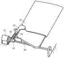
Fig. 1 is a schematic diagram of the general structure of a large underwater vehicle with a self-disposable wing according to the invention.
FIG. 2 is a cross-sectional view of a bow assembly 1/4 according to the present invention.
FIG. 3 is a schematic cross-sectional view of a mid-section assembly 1/4 of the present invention.
Fig. 4 is a schematic cross-sectional view of the tail assembly 1/2 of the present invention.
Fig. 5 is a schematic view of the structure of the cross rudder of the present invention.
Fig. 6 is a cross-sectional structural view of the cross rudder of the present invention.
Fig. 7 is a schematic view of the structure of the self-releasing wing of the present invention.
Reference numerals: 1-a bow assembly, 2-a middle cabin section, 3-a tail cabin section, 4-a cable throwing module, 5-a bow outer shell, 6-a bow connecting ring, 7-a front buoyancy adjusting module, 8-a front connecting fixed block, 9-a front glass fiber reinforced plastic outer shell, 10-a rear glass fiber reinforced plastic shell, 11-a rear connecting fixed block and 12-a wing unit; 13-a rear buoyancy adjustment module; 14-communication antenna, 15-communication module, 16-load rejection, 17-cross rudder, 18-propeller, 19-middle cabin front connecting ring, 20-middle cabin shell, 21-power module, 22-attitude adjusting module, 23-control module, 24-middle cabin rear connecting ring, 25-horizontal rudder, 26-rudder frame, 27-vertical rudder, 28-movable rudder surface, 29-bow-shaped connecting shaft, 30-steering engine, 31-steering engine fixing frame, 32-movable rudder surface connecting shaft, 33-compensator, W1-motor, W2-shaft coupling, W3-limiting rod, W4-wing body, W5-screw nut, W6-lead screw and R1-revolute pair
Detailed Description
The invention is described in further detail below with reference to the figures and specific examples. It should be understood that the specific embodiments described herein are merely illustrative of the invention and are not intended to limit the invention.
Example 1: the invention provides a large underwater vehicle with disposable wings, the whole appearance of which is shown in figure 1, and the large underwater vehicle comprises a bow assembly 1, a middle assembly 2, a tail assembly 3 and wing units 12; referring to fig. 2, the bow assembly 1 comprises a cable throwing module 4, a bow outer shell 5, a bow connecting ring 6, a front buoyancy adjusting module 7, a front connecting fixing block 8 and a front glass fiber reinforced plastic outer shell 9; the cable throwing module 4 is fixedly connected with the front end of the bow outer shell 5 through eight annular bolts; the bow shell 5 is connected with the front glass fiber reinforced plastic shell 9 through a bow connecting ring 6 in a mode of being fixedly connected through ten annularly and uniformly distributed bolts; the front connecting and fixing blocks 8 are eight in number and are provided with through holes, and the front glass fiber reinforced plastic shell 9, the front connecting and fixing blocks 8 and the front buoyancy adjusting module 7 are screwed on the threaded hole of the front buoyancy adjusting module 7 through bolts penetrating through the through holes in the connecting and fixing blocks 8 so as to be fixed together; the cable throwing module 4 can throw a section of cable when the underwater vehicle finishes a task and returns to the water surface, so that a recovery worker can conveniently catch the cable to capture the underwater vehicle;
referring to fig. 3, the middle assembly 2 comprises a middle cabin front connecting ring 19, a middle cabin outer shell 20, a power module 21, an attitude adjusting module 22, a control module 23 and a middle cabin rear connecting ring 24, wherein the power module 21 provides energy for the underwater vehicle, the attitude adjusting module 22 can adjust the pitching attitude of the underwater vehicle, and the control module 23 is used for controlling the operation of the whole underwater vehicle and processing and storing information detected by sensors;
referring to fig. 4, the tail assembly 3 includes a rear glass fiber reinforced plastic housing 10, a rear connection fixing block 11, a rear buoyancy adjusting module 13, a communication antenna 14, a communication module 15, a load rejection 16, a cross rudder 17, and a propeller 18; the rear connecting fixed blocks 11 are eight in number and provided with through holes, and the rear glass fiber reinforced plastic shell 10, the rear connecting fixed blocks 11 and the rear buoyancy adjusting module 13 are screwed to the threaded holes of the rear buoyancy adjusting module 13 through the through holes of the rear connecting fixed blocks 11 by bolts so as to be fixedly connected together; the communication module 15 is fixedly connected with the rear glass fiber reinforced plastic shell 10 through bolts; the communication antenna 14 is connected with the communication module 15, the load rejection 16 is positioned below the rear glass fiber reinforced plastic shell 10 and fixed with the rear glass fiber reinforced plastic shell 10 through bolts; the cross rudder 17 is arranged behind the rear glass fiber reinforced plastic shell 10 and used for adjusting the course of the large-scale heavy-load underwater vehicle driven by the double buoyancy mixture; the propeller 18 is arranged at the tail end of the tail assembly and is used for propelling the large heavy-load underwater vehicle with double buoyancy force hybrid drive forwards;
referring to fig. 5 and 6, the cross rudder 17 is composed of a horizontal rudder 25, a rudder frame 26, a vertical rudder 27, a movable rudder surface 28, a bow-shaped connecting shaft 29, a steering engine 30, a steering engine fixing frame 31, a movable rudder surface connecting shaft 32 and a compensator 33; the horizontal rudder 25 is fixed with the horizontal direction of the rudder carrier 26 through bolts; the vertical rudder 27 is fixed with the vertical direction of the rudder carrier 26 by bolts; each vertical rudder 27 is movably connected with a movable rudder surface 28 through a movable rudder surface connecting shaft 32, and each movable rudder surface connecting shaft 32 passes through the shaft hole on the rudder frame 26 and is respectively connected with two ends of the Chinese character bow connecting shaft 29; the compensator 33 is connected with an oil inlet of the steering engine 30 through an oil pipe and is used for balancing the pressure inside and outside the steering engine; when the steering engine rotates, the Chinese character 'gong' connecting shaft is driven to rotate, the Chinese character 'gong' connecting shaft drives the movable control surface connecting shafts at the two ends to rotate, and the two movable control surfaces are driven to rotate because the movable control surface connecting shafts are fixedly connected with the movable control surfaces; the cross rudder controls the course of the underwater vehicle by adjusting the rotation angles of the two vertical movable control surfaces.
Referring to fig. 7, the wing unit 12 includes a wing clamping and releasing mechanism and a wing body W4, and the wing clamping and releasing mechanism includes a motor W1, a coupling W2, a limiting rod W3, a nut W5, and a lead screw W6. Motor W1 passes through motor flange mounting inside rear glass steel housing 10, motor output shaft and shaft coupling one end are connected admittedly, the other end and the lead screw W6 input of shaft coupling are connected admittedly, the lead screw W6 other end is connected inside rear glass steel housing 10 through the revolute pair, screw W5 installs on lead screw W6, screw W5's cylindric arch is connected with the logical groove of gag lever post, gag lever post W3 installs inside rear glass steel housing 10 through revolute pair R1, there is protruding structure on gag lever post W3, wing body W4 contains the part of stretching in and the part of extending, the part of stretching in has the inclined plane, this inclined plane can contact with the screw, the part of extending is last to have a recess, the protruding structure of gag lever post can block in the recess.
Referring to fig. 7, the operation of the autonomous jettison wing is as follows: fig. 7 shows the installation positions of the various components of the wing unit, with the motor W1 in a locked state, when the wing needs to be abandoned, the motor W1 starts to rotate, the coupler W2 drives the lead screw W6 to rotate, the nut W5 moves towards the direction close to the wing, the nut W5 drives the limiting rod W3 to rotate around the revolute pair R1, the protruding structure of the limiting rod W3 starts to gradually leave the groove of the extending part of the wing, when the protruding structure of the limiting rod W3 completely leaves the groove of the wing extension portion, the wing can move along the radial direction of an aircraft, the nut W5 continues to move towards the direction close to the wing, the nut W5 starts to gradually contact with the inclined plane of the wing extension portion, the wing gradually moves away from the aircraft along the radius of the aircraft along with the movement of the nut W5 until the wing drops, the motor W1 stops rotating, and whether the wing drops can be judged through the change of the motor driving current.
Example 2: the large-scale heavy-load underwater vehicle with the double buoyancy hybrid power provided by the embodiment 1 is applied to underwater glide detection navigation without propulsion, and the propeller is always in a closed state.
The submergence process is as follows: before the diving process, the underwater vehicle floats on the water surface in a neutral buoyancy state, after the diving mode is started, the control module 23 sends a signal to control the attitude adjusting module 22 to adjust the attitude, and then controls the front and rear buoyancy adjusting modules 7 and 13 to reduce the overall buoyancy of the underwater vehicle, so that the diving is realized, the control module 23 controls a carried sensor to measure and store the signal in the diving process, and meanwhile, the attitude adjusting module 22 and the cross rudder 17 are controlled to ensure the gliding attitude and the course;
the floating process is as follows: after the underwater vehicle submerges to the target depth, the control module 23 sends a command to control the attitude adjusting module 22 to adjust the attitude, and controls the front and rear buoyancy adjusting modules 7 and 13 to increase the overall buoyancy of the underwater vehicle, so that the underwater vehicle floats upwards, the control module 23 controls a sensor carried by the underwater vehicle to measure and store signals in the floating process, and meanwhile, the attitude adjusting module 22 and the cross rudder 17 are controlled to ensure the gliding attitude and the heading;
the communication process is as follows: when the underwater vehicle floats to the water surface, the control module 23 sends a command to control the communication module 15 to carry out signal communication with the roadbed console, transmits an acquired signal to the console, and receives a control command sent by the console to carry out navigation tasks of the next section;
the cable throwing process comprises the following steps: when the underwater vehicle floats to the water surface after completing the operation task, the control module 23 controls the cable throwing module 4 to throw out the cable, so that the recovery personnel can conveniently capture the underwater vehicle;
the attitude adjusting process of the double-buoyancy adjusting module comprises the following steps: if the attitude adjusting module 22 fails to normally adjust the attitude during the operation, if the underwater vehicle is heavy in front and light in back, the vehicle is in an excessively low head state, the control module 23 controls the front buoyancy adjusting module 7 to increase the buoyancy, and the back buoyancy adjusting module 13 to decrease the buoyancy, and if the underwater vehicle is light in front and heavy in back, the vehicle is in an excessively high head state, and the control module 23 controls the front buoyancy adjusting module 7 to decrease the buoyancy, and the back buoyancy adjusting module 13 to increase the buoyancy.
Example 3: the large-scale heavy-load underwater vehicle with double buoyancy hybrid power provided by the embodiment 1 is applied to carry out underwater propulsion depth-fixing exploration navigation.
Submerging to the target depth process: after the diving mode is started, the control module 23 sends a signal to control the attitude adjusting module 22 to adjust the attitude, and then controls the front and rear buoyancy adjusting modules 7 and 13 to reduce the total buoyancy of the underwater vehicle, so that the diving is realized;
the depth-setting detection cruise process comprises the following steps: when the underwater vehicle dives to the target depth, the control module 23 controls the carried sensor to measure and store signals, and controls the attitude adjusting module 22 and the cross rudder 17 to ensure the gliding attitude and the heading, so that the underwater vehicle is always in the target depth range and in a horizontal sailing state;
the floating process: after the fixed-depth detection cruise operation is completed, the control module 23 sends a command to control the attitude adjusting module 22 to adjust the attitude, and controls the front and rear buoyancy adjusting modules 7 and 13 to increase the total buoyancy of the underwater vehicle, so that the underwater vehicle floats upwards, and communicates with the roadbed main control console after reaching the water surface.
The present invention is not limited to the above-described embodiments. The foregoing description of the specific embodiments is intended to describe and illustrate the technical solutions of the present invention, and the above specific embodiments are merely illustrative and not restrictive. Those skilled in the art can make many changes and modifications to the invention without departing from the spirit and scope of the invention as defined in the appended claims.