CN110635888B - Dynamic indication of Time Division Duplex (TDD) uplink/downlink subframe configuration - Google Patents
Dynamic indication of Time Division Duplex (TDD) uplink/downlink subframe configuration Download PDFInfo
- Publication number
- CN110635888B CN110635888B CN201910966550.1A CN201910966550A CN110635888B CN 110635888 B CN110635888 B CN 110635888B CN 201910966550 A CN201910966550 A CN 201910966550A CN 110635888 B CN110635888 B CN 110635888B
- Authority
- CN
- China
- Prior art keywords
- control channel
- downlink control
- frame
- common downlink
- subframes
- Prior art date
- Legal status (The legal status is an assumption and is not a legal conclusion. Google has not performed a legal analysis and makes no representation as to the accuracy of the status listed.)
- Active
Links
Images


Classifications
-
- H—ELECTRICITY
- H04—ELECTRIC COMMUNICATION TECHNIQUE
- H04L—TRANSMISSION OF DIGITAL INFORMATION, e.g. TELEGRAPHIC COMMUNICATION
- H04L5/00—Arrangements affording multiple use of the transmission path
- H04L5/003—Arrangements for allocating sub-channels of the transmission path
- H04L5/0037—Inter-user or inter-terminal allocation
-
- H—ELECTRICITY
- H04—ELECTRIC COMMUNICATION TECHNIQUE
- H04W—WIRELESS COMMUNICATION NETWORKS
- H04W72/00—Local resource management
- H04W72/20—Control channels or signalling for resource management
- H04W72/23—Control channels or signalling for resource management in the downlink direction of a wireless link, i.e. towards a terminal
-
- H—ELECTRICITY
- H04—ELECTRIC COMMUNICATION TECHNIQUE
- H04L—TRANSMISSION OF DIGITAL INFORMATION, e.g. TELEGRAPHIC COMMUNICATION
- H04L5/00—Arrangements affording multiple use of the transmission path
- H04L5/003—Arrangements for allocating sub-channels of the transmission path
- H04L5/0053—Allocation of signaling, i.e. of overhead other than pilot signals
-
- H—ELECTRICITY
- H04—ELECTRIC COMMUNICATION TECHNIQUE
- H04L—TRANSMISSION OF DIGITAL INFORMATION, e.g. TELEGRAPHIC COMMUNICATION
- H04L5/00—Arrangements affording multiple use of the transmission path
- H04L5/0091—Signaling for the administration of the divided path
-
- H—ELECTRICITY
- H04—ELECTRIC COMMUNICATION TECHNIQUE
- H04L—TRANSMISSION OF DIGITAL INFORMATION, e.g. TELEGRAPHIC COMMUNICATION
- H04L5/00—Arrangements affording multiple use of the transmission path
- H04L5/14—Two-way operation using the same type of signal, i.e. duplex
- H04L5/1469—Two-way operation using the same type of signal, i.e. duplex using time-sharing
-
- H—ELECTRICITY
- H04—ELECTRIC COMMUNICATION TECHNIQUE
- H04W—WIRELESS COMMUNICATION NETWORKS
- H04W76/00—Connection management
- H04W76/20—Manipulation of established connections
- H04W76/28—Discontinuous transmission [DTX]; Discontinuous reception [DRX]
Abstract
A method and apparatus for dynamic indication of Time Division Duplex (TDD) uplink/downlink subframe configuration. Aspects of the present disclosure relate to techniques for dynamically indicating a Time Division Duplex (TDD) Uplink (UL)/Downlink (DL) subframe configuration to a user equipment. The base station may identify one or more anchor subframes and one or more non-anchor subframes in the frame. The base station may dynamically change an UL/DL link configuration of the frame for communicating with a plurality of User Equipments (UEs), and transmit the changed configuration using a common downlink control channel interpretable by the plurality of UEs in at least one of the one or more anchor subframes of the frame.
Description
The application is a divisional application of Chinese patent application with application number 201480042170.4 (PCT/CN2014/082118) and application date 7/14/2014, named as dynamic indication of Time Division Duplex (TDD) uplink/downlink subframe configuration.
Claiming priority based on 35U.S.C. § 119
This patent application claims priority from PCT application No. PCT/CN2013/081188 entitled "DYNAMIC information OF TIME differentiation (TDD) DUPLEX UPLINK/DOWNLINK SUBFRAME CONFIGURATIONS" filed on 29.7.2013 and PCT application No. PCT/CN2013/081188 entitled "DYNAMIC information OF TIME differentiation (TDD) DUPLEX UPLINK/DOWNLINK SUBFRAME CONFIGURATIONS" filed on 9.8.2013, and assigned to the assignee hereof, and hereby expressly incorporated by reference.
Technical Field
The present disclosure relates generally to wireless communications, and more particularly to methods and apparatus for dynamic indication of Time Division Duplex (TDD) Uplink (UL)/Downlink (DL) subframe configuration.
Background
Wireless communication systems are widely deployed to provide various telecommunication services such as telephony, video, data, messaging, and broadcasting. Typical wireless communication systems may employ multiple-access techniques capable of supporting communication with multiple users by sharing the available system resources (e.g., bandwidth, transmit power). Examples of such multiple-access techniques include Code Division Multiple Access (CDMA) systems, Time Division Multiple Access (TDMA) systems, Frequency Division Multiple Access (FDMA) systems, Orthogonal Frequency Division Multiple Access (OFDMA) systems, single carrier frequency division multiple access (SC-FDMA) systems, and time division synchronous code division multiple access (TD-SCDMA) systems.
These multiple access techniques have been employed in a variety of telecommunications standards to provide a common protocol that enables different wireless devices to communicate on a local, national, regional, and even global level. An example of an emerging telecommunications standard is Long Term Evolution (LTE). LTE/LTE-advanced is an enhanced set of Universal Mobile Telecommunications System (UMTS) mobile standards promulgated by the third generation partnership project (3 GPP). LTE/LTE-advanced is designed to better support mobile broadband internet access by improving spectral efficiency, reducing costs, improving services, utilizing new spectrum, and better integrate with other open standards using OFDMA on the Downlink (DL), SC-FDMA on the Uplink (UL), and multiple-input multiple-output (MIMO) antenna technology. However, as the demand for mobile broadband access continues to grow, there is a need for further improvements in LTE technology. Preferably, these improvements should be applicable to other multiple access techniques and telecommunications standards employing these techniques.
Disclosure of Invention
Certain aspects of the present disclosure provide a method for wireless communications by a base station. The method generally comprises: the method includes identifying one or more anchor subframes and one or more non-anchor subframes in a frame, dynamically changing an uplink/downlink configuration of the frame for communicating with a plurality of User Equipments (UEs), and transmitting the changed configuration using a common downlink control channel interpretable by the plurality of UEs in at least one of the one or more anchor subframes of the frame.
Certain aspects of the present disclosure provide a method for wireless communication by a user equipment. The method generally comprises: monitoring one or more anchor subframes of a frame for a common downlink control channel, wherein the common downlink control channel indicates a changed uplink/downlink configuration of subframes used for communicating with at least the UE, and decoding the common downlink control channel to determine the changed uplink/downlink configuration of subframes used in subsequent communications.
Certain aspects of the present disclosure provide an apparatus for wireless communications by a base station. The apparatus generally comprises: the apparatus generally includes means for identifying one or more anchor subframes and one or more non-anchor subframes in a frame, means for dynamically changing an uplink/downlink configuration of the frame for communicating with a plurality of User Equipments (UEs), and means for transmitting the changed configuration using a common downlink control channel interpretable by the plurality of UEs in at least one of the one or more anchor subframes of the frame.
Certain aspects of the present disclosure provide an apparatus for wireless communication by a user equipment. The apparatus generally comprises: means for monitoring one or more anchor subframes of a frame for a common downlink control channel, wherein the common downlink control channel indicates a changed uplink/downlink configuration of subframes used for communicating with at least the UE, and means for decoding the common downlink control channel to determine the changed uplink/downlink configuration of subframes used in subsequent communications.
Aspects generally include methods, apparatus, systems, computer program products, and processing systems, substantially as described herein with reference to and as illustrated by the accompanying drawings. "LTE" generally refers to LTE and LTE advanced (LTE-a).
Drawings
Fig. 1 is a diagram illustrating an example of a network architecture.
Fig. 2 is a diagram illustrating an example of an access network.
Fig. 3 is a diagram showing an example of a DL frame structure in LTE.
Fig. 4 is a diagram showing an example of a UL frame structure in LTE.
Fig. 5 is a diagram illustrating an example of a radio protocol architecture for the user plane and the control plane.
Fig. 6 is a diagram illustrating an example of an evolved node B and user equipment in an access network in accordance with certain aspects of the present disclosure.
Fig. 7 shows a list of uplink/downlink subframe configurations.
Fig. 8 shows an example subframe frame format.
Fig. 9 shows an example use of a reference uplink/downlink subframe configuration.
Fig. 10 illustrates an example transmission of a common PDCCH in accordance with aspects of the present disclosure.
Fig. 11 illustrates example transmissions of a common PDCCH at different locations in different cells in accordance with aspects of the disclosure.
Fig. 12 illustrates example operations performed by, for example, a Base Station (BS) for dynamic indication of TDD UL/DL subframe configurations in accordance with aspects of the present disclosure.
Fig. 13 illustrates example operations performed by, for example, a User Equipment (UE) for dynamic indication of TDD UL/DL subframe configurations in accordance with aspects of the present disclosure.
Detailed Description
The detailed description set forth below in connection with the appended drawings is intended as a description of various configurations and is not intended to represent the only configurations in which the concepts described herein may be practiced. The detailed description includes specific details for the purpose of providing a thorough understanding of the various concepts. It will be apparent, however, to one skilled in the art that these concepts may be practiced without these specific details. In some instances, well-known structures and components are shown in block diagram form in order to avoid obscuring such concepts.
Several aspects of a telecommunications system will now be presented with reference to various apparatus and methods. These apparatus and methods will be described in the following detailed description and illustrated in the accompanying drawings by various blocks, modules, components, circuits, steps, processes, algorithms, etc. (collectively referred to as "elements"). These elements may be implemented using hardware, software, or a combination thereof. Whether such elements are implemented as hardware or software depends upon the particular application and design constraints imposed on the overall system.
For example, an element or any portion of an element or any combination of elements may be implemented with a "processing system" that includes one or more processors. Examples of processors include microprocessors, microcontrollers, Digital Signal Processors (DSPs), Field Programmable Gate Arrays (FPGAs), Programmable Logic Devices (PLDs), state machines, gated logic, discrete hardware circuits, and other suitable hardware configured to perform the various functions described throughout this disclosure. One or more processors in the processing system may execute software. Software shall be construed broadly to mean instructions, instruction sets, code segments, program code, programs, subroutines, software modules, applications, software packages, firmware, routines, subroutines, objects, executables, threads of execution, procedures, functions, etc., whether referred to as software/firmware, middleware, microcode, hardware description language, or other terminology.
Thus, in one or more exemplary embodiments, the functions described may be implemented in hardware, software, or a combination thereof. If implemented in software, the functions may be stored on or encoded on a computer-readable medium as one or more instructions or code. Computer readable media includes computer storage media. A storage media may be any available media that can be accessed by a computer. By way of example, and not limitation, such computer-readable media can comprise RAM, ROM, EEPROM, PCM (phase change memory), flash memory, CD-ROM or other optical disk storage, magnetic disk storage or other magnetic storage devices, or any other medium that can be used to carry or store desired program code in the form of instructions or data structures and that can be accessed by a computer. Disk and disc, as used herein, includes Compact Disc (CD), laser disc, optical disc, Digital Versatile Disc (DVD), floppy disk and blu-ray disc where disks usually reproduce data magnetically, while discs reproduce data optically with lasers. Combinations of the above should also be included within the scope of computer-readable media.
Fig. 1 is a diagram illustrating an LTE network architecture 100. The LTE network architecture 100 may be referred to as an Evolved Packet System (EPS) 100. The EPS 100 may include one or more User Equipment (UE) 102, an evolved UMTS terrestrial radio access network (E-UTRAN)104, an Evolved Packet Core (EPC) 110, a Home Subscriber Server (HSS)120, and operator IP services 122. The EPS may interconnect with other access networks, but those entities/interfaces are not shown for simplicity. Exemplary other access networks may include IP Multimedia Subsystem (IMS) PDNs, internet PDNs, management PDNs (e.g., configuration PDNs), carrier-specific PDNs, operator-specific PDNs, and/or GPS PDNs. As shown, the EPS provides packet switched services, however, those skilled in the art will readily recognize that the various concepts presented throughout this disclosure may be extended to networks providing circuit switched services.
The E-UTRAN includes evolved node Bs (eNBs) 106 and other eNBs 108. The eNB 106 provides user and control plane protocol terminations toward the UE 102. eNB 106 may connect to other enbs 108 via an X2 interface (e.g., backhaul). The eNB 106 may also be referred to as a base station, a base transceiver station, a wireless base station, a wireless transceiver, a transceiver function, a Basic Service Set (BSS), an Extended Service Set (ESS), an access point, or some other suitable terminology. eNB 106 provides an access point for UE 102 to EPC 110. Examples of UEs 102 include a cellular phone, a smart phone, a Session Initiation Protocol (SIP) phone, a laptop, a Personal Digital Assistant (PDA), a satellite radio, a global positioning system, a multimedia device, a video device, a digital audio player (e.g., MP3 player), a camera, a gaming console, a tablet, a netbook, a smartbook, an ultrabook, or any other similarly capable device. UE 102 may also be referred to by those skilled in the art as a mobile station, a subscriber station, a mobile unit, a subscriber unit, a wireless unit, a remote unit, a mobile device, a wireless communications device, a remote device, a mobile subscriber station, an access terminal, a mobile terminal, a wireless terminal, a remote terminal, a handset, a user agent, a mobile client, a client, or some other suitable terminology.
Fig. 2 is a diagram illustrating an example of an access network 200 in an LTE network architecture. In this example, the access network 200 is divided into a plurality of cellular regions (cells) 202. One or more lower power class enbs 208 may have cellular regions 210 that overlap with one or more of cells 202. The lower power class eNB 208 may be referred to as a Remote Radio Head (RRH). The lower power class eNB 208 may be a femto cell (e.g., a home eNB (henb)), pico cell, or micro cell. Macro enbs 204 are each assigned to a respective cell 202 and are configured to provide access points to EPC 110 for all UEs 206 in cells 202. There is no centralized controller in this example of the access network 200, but a centralized controller may be used in alternative configurations. The eNB 204 is responsible for all radio related functions including radio bearer control, admission control, mobility control, scheduling, security, and connectivity to the serving gateway 116. The network 200 may also include one or more repeaters (not shown). According to one application, the UE may act as a relay.
The modulation and multiple access scheme employed by the access network 200 may vary depending on the particular telecommunications standard being deployed. In LTE applications, OFDM is used on the DL and SC-FDMA is used on the UL to support both Frequency Division Duplex (FDD) and Time Division Duplex (TDD). As those skilled in the art will readily recognize from the detailed description that follows, the various concepts presented herein are well suited for LTE applications. However, these concepts can be readily extended to other telecommunications standards employing other modulation and multiple access techniques. These concepts may be extended to evolution-data optimized (EV-DO) or Ultra Mobile Broadband (UMB), for example. EV-DO and UMB are air interface standards promulgated by the third generation partnership project 2(3GPP2) as part of the CDMA2000 family of standards and employ CDMA to provide broadband internet access to mobile stations. These concepts may also be extended to Universal Terrestrial Radio Access (UTRA) employing wideband-CDMA (W-CDMA) and other variants of CDMA such as TD-SCDMA; global system for mobile communications (GSM) using TDMA; and evolved UTRA (E-UTRA), Ultra Mobile Broadband (UMB), IEEE 802.11 (Wi-Fi), IEEE 802.16(WiMAX), IEEE 802.20, and flash OFDM employing OFDMA. UTRA, E-UTRA, UMTS, LTE, and GSM are described in documents from 3GPP organizations. CDMA2000 and UMB are described in documents from the organization of 3GPP 2. The actual wireless communication standard and multiple access technique employed will depend on the particular application and the overall design constraints imposed on the system.
The eNB 204 may have multiple antennas supporting MIMO technology. The use of MIMO technology enables eNB 204 to utilize the spatial domain to support spatial multiplexing, beamforming, and transmit diversity. Space division multiplexing may be used to transmit different data streams simultaneously on the same frequency. The data stream may be sent to a single UE 206 to increase the data rate or to multiple UEs 206 to increase the overall system capacity. This is achieved by spatially precoding each data stream (e.g., applying a scaling of amplitude and phase) and then transmitting each spatially precoded stream over multiple transmit antennas on the DL. Spatially precoded data streams with different spatial characteristics arrive at the UE 206, which enables each of the UEs 206 to recover one or more data streams destined for that UE 206. On the UL, each UE 206 transmits a spatially precoded data stream, which enables the eNB 204 to identify the source of each spatially precoded data stream.
Spatial multiplexing is typically used when channel conditions are good. Beamforming may be used to focus the transmitted energy in one or more directions when channel conditions are not too good. This may be achieved by spatially precoding data for transmission over multiple antennas. To achieve good coverage at the cell edge, single stream beamforming transmission may be used in conjunction with transmit diversity.
In the detailed description that follows, various aspects of an access network will be described with reference to a MIMO system supporting OFDM on the DL. OFDM is a spread spectrum technique that modulates data over multiple subcarriers within an OFDM symbol. The subcarriers are spaced apart at precise frequencies. The spacing provides "orthogonality" which enables the receiver to recover the data from the subcarriers. In the time domain, a guard interval (e.g., a cyclic prefix) may be added to each OFDM symbol to combat inter-OFDM symbol interference. The UL may use SC-FDMA in the form of DFT-spread OFDM signal to compensate for high peak-to-average power ratio (PAPR).
Fig. 3 is a schematic diagram 300 showing an example of a DL frame structure in LTE. A frame (10ms) may be divided into 10 equally sized subframes with indices of 0 through 9. Each subframe may include two consecutive slots. A resource grid may be used to represent two slots, each slot comprising resource blocks. The resource grid is divided into a plurality of resource elements. In LTE, a resource block contains 12 consecutive subcarriers in the frequency domain and 7 consecutive OFDM symbols in the time domain, or 84 resource elements, for a conventional cyclic prefix in each OFDM symbol. For an extended cyclic prefix, a resource block contains 6 consecutive OFDM symbols in the time domain and has 72 resource elements. Some of the resource elements indicated as R302, R304 include DL reference signals (DL-RS). The DL-RS includes cell-specific RS (crs) (also sometimes referred to as common RS)302 and UE-specific RS (UE-RS) 304. The UE-RS 304 is transmitted only on resource blocks on which the corresponding Physical DL Shared Channel (PDSCH) is mapped. The number of bits carried by each resource element depends on the modulation scheme. Thus, the more resource blocks a UE receives and the higher the modulation scheme, the higher the data rate for that UE.
In LTE, an eNB may transmit a Primary Synchronization Signal (PSS) and a Secondary Synchronization Signal (SSS) for each cell in the eNB. The primary and secondary synchronization signals may be transmitted within symbol periods 6 and 5, respectively, in each of subframes 0 and 5 of each radio frame with a normal Cyclic Prefix (CP). The synchronization signal may be used by the UE for cell detection and acquisition. The eNB may send a Physical Broadcast Channel (PBCH) in symbol periods 0 through 3 in slot 1 of subframe 0. The PBCH may carry certain system information.
The eNB may transmit a Physical Control Format Indicator Channel (PCFICH) in the first symbol period of each subframe. The PCFICH may convey the number of symbol periods (M) used for the control channel, where M may be equal to 1,2, or 3, and may vary by factor of a frame. M may also be equal to 4 for a small system bandwidth, e.g., having less than 10 resource blocks. The eNB may transmit a Physical HARQ Indicator Channel (PHICH) and a Physical Downlink Control Channel (PDCCH) in the first M symbol periods of each subframe. The PHICH may carry information to support hybrid automatic repeat request (HARQ). The PDCCH may carry information on resource allocation for the UE and control information for a downlink channel. The eNB may transmit a Physical Downlink Shared Channel (PDSCH) for the remaining symbol periods of each subframe. The PDSCH may carry data for UEs scheduled with data transmission on the downlink.
The eNB may transmit the PSS, SSS, and PBCH in the center 1.08MHz of the system bandwidth used by the eNB. The eNB may transmit these channels over the entire system bandwidth in each symbol period in which the PCFICH and PHICH are transmitted. The eNB may transmit the PDCCH to the group of UEs in some portion of the system bandwidth. The eNB may transmit the PDSCH to a particular UE in a particular portion of the system bandwidth. The eNB may transmit PSS, SSS, PBCH, PCFICH, and PHICH to all UEs in a broadcast manner, may transmit PDCCH to a specific UE in a unicast manner, and may also transmit PDSCH to a specific UE in a unicast manner.
In each symbol period, multiple resource elements may be available. Each Resource Element (RE) may cover one subcarrier in one symbol period and may be used to transmit one modulation symbol, which may be a real or complex value. Resource elements in each symbol period that are not used for reference signals may be arranged into Resource Element Groups (REGs). Each REG may include four resource elements in one symbol period. The PCFICH may occupy four REGs in symbol period 0, which may be approximately equally spaced in frequency. The PHICH may occupy three REGs, which may be spread over frequency, in one or more configurable symbol periods. For example, the three REGs for the PHICH may all belong to symbol period 0 or may be spread in symbol periods 0, 1, and 2. For example, the PDCCH may occupy 9, 18, 36, or 72 REGs in the first M symbol periods, which may be selected from the available REGs. Only certain REG combinations may be allowed for PDCCH. In aspects of the present methods and apparatus, a subframe may include more than one PDCCH.
The UE may know specific REGs for PHICH and PCFICH. The UE may search for different REG combinations for the PDCCH. The number of combinations to be searched is typically less than the number of allowed combinations for PDCCH. The eNB may transmit the PDCCH to the UE in any of the combinations that the UE is to search for.
Fig. 4 is a schematic diagram 400 showing an example of a UL frame structure in LTE. The available resource blocks for the UL may be divided into a data portion and a control portion. The control portion may be formed at both edges of the system bandwidth and may have a configurable size. The resource blocks in the control portion may be allocated to the UE for transmission of control information. The data section may include all resource blocks not included in the control section. The UL frame structure is such that the data portion includes contiguous subcarriers, which may allow all of the contiguous subcarriers in the data portion to be allocated to a single UE.
The resource blocks 410a, 410b in the control section may be allocated to the UE to transmit control information to the eNB. The resource blocks 420a, 420b in the data portion may also be allocated to the UE to transmit data to the eNB. The UE may send control information in a Physical UL Control Channel (PUCCH) on the allocated resource blocks in the control section. The UE may transmit only data or both data and control information on the allocated resource blocks in the data section in a Physical UL Shared Channel (PUSCH). The UL transmission may span both slots of a subframe and may hop across frequency.
The initial system access may be performed using a set of resource blocks and UL synchronization may be achieved in a Physical Random Access Channel (PRACH) 430. The PRACH 430 carries a random sequence and cannot carry any UL data/signaling. Each random access preamble occupies a bandwidth corresponding to 6 consecutive resource blocks. The starting frequency is specified by the network. That is, the transmission of the random access preamble is limited to certain time and frequency resources. There is no frequency hopping for PRACH. The PRACH attempt is carried in a sequence of a single subframe (1ms) or a few consecutive subframes, and the UE is only able to make a single PRACH attempt per frame (10 ms).
Fig. 5 is a schematic diagram 500 illustrating an example of a radio protocol architecture for the user plane and the control plane in LTE. The radio protocol architecture for the UE and eNB is shown with three layers: layer 1, layer 2, and layer 3. Layer 1(L1 layer) is the lowest layer and implements various physical layer signal processing functions. The L1 layer will be referred to herein as the physical layer 506. Layer 2(L2 layer) 508 is located above the physical layer 506 and is responsible for the link between the UE and the eNB on the physical layer 506.
In the user plane, the L2 layer 508 includes: a Medium Access Control (MAC) sublayer 510, a Radio Link Control (RLC) sublayer 512, and a Packet Data Convergence Protocol (PDCP)514 sublayer, which terminate at the eNB on the network side. Although not shown, the UE may have several upper layers above the L2 layer 508, including a network layer (e.g., IP layer) that terminates at the PDN gateway 118 on the network side, and an application layer that terminates at the other end of the connection (e.g., far end UE, server, etc.).
The PDCP sublayer 514 provides multiplexing between different radio bearers and logical channels. The PDCP sublayer 514 also provides header compression for upper layer data packets to reduce radio transmission overhead, security by ciphering the data packets, and handover support for UEs between enbs. The RLC sublayer 512 provides segmentation and reassembly of upper layer data packets, retransmission of lost data packets, and reordering of data packets to compensate for out-of-order reception caused by hybrid automatic repeat request (HARQ). The MAC sublayer 510 provides multiplexing between logical channels and transport channels. The MAC sublayer 510 is also responsible for allocating various radio resources (e.g., resource blocks) among UEs in one cell. The MAC sublayer 510 is also responsible for HARQ operations.
In the control plane, the radio protocol architecture for the UE and eNB is essentially the same for the physical layer 506 and the L2 layer 508, except that there is no header compression function for the control plane. The control plane also includes a Radio Resource Control (RRC) sublayer 516 in layer 3 (layer L3). The RRC sublayer 516 is responsible for obtaining radio resources (e.g., radio bearers) and configuring the lower layers using RRC signaling between the eNB and the UE.
Fig. 6 is a block diagram of an eNB 610 in communication with a UE 650 in an access network. In the DL, upper layer packets from the core network are provided to a controller/processor 675. The controller/processor 675 implements the functionality of the L2 layer. In the DL, the controller/processor 675 provides header compression, ciphering, packet segmentation and reordering, multiplexing between logical and transport channels, and radio resource allocation to the UE 650 based on various priority metrics. The controller/processor 675 is also responsible for HARQ operations, retransmission of lost packets, and signaling to the UE 650.
At the UE 650, each receiver 654RX receives a signal through its respective antenna 652. Each receiver 654RX recovers information modulated on an RF carrier and provides the information to a Receiver (RX) processor 656. The RX processor 656 performs various signal processing functions at the L1 layer. The RX processor 656 performs spatial processing on the information to recover any spatial streams destined for the UE 650. If multiple spatial streams are intended for the UE 650, they may be combined into a single OFDM symbol stream by an RX processor 656. The RX processor 656 then converts the OFDM symbol stream from the time-domain to the frequency domain using a Fast Fourier Transform (FFT). The frequency domain signal includes a separate OFDM symbol stream for each subcarrier in the OFDM signal. The symbols and reference signals on each subcarrier are recovered and demodulated by determining the most likely signal constellation points transmitted by the eNB 610. These soft decisions may be based on channel estimates computed by the channel estimator 658. The soft decisions are then decoded and deinterleaved to recover the data and control signals that were originally transmitted by the eNB 610 on the physical channel. The data and control signals are then provided to the controller/processor 659.
The controller/processor 659 implements the L2 layer. The controller/processor can be associated with a memory 660 that stores program codes and data. The memory 660 may be referred to as a computer-readable medium. In the UL, the controller/processor 659 provides demultiplexing between transport and logical channels, packet reassembly, deciphering, header decompression, control signal processing to recover upper layer packets from the core network. The upper layer packets are then provided to a data sink 662, which data sink 662 represents all protocol layers above the L2 layer. Various control signals may also be provided to a data sink 662 for processing by L3. The controller/processor 659 is also responsible for error detection using Acknowledgement (ACK) and/or Negative Acknowledgement (NACK) protocols to support HARQ operations.
In the UL, a data source 667 is used to provide upper layer packets to the controller/processor 659. The data source 667 represents all protocol layers above the L2 layer. Similar to the functionality described in connection with the DL transmission by the eNB 610, the controller/processor 659 implements the L2 layer for the user plane and the control plane by providing header compression, ciphering, packet segmentation and reordering, and multiplexing between logical and transport channels based on radio resource allocations by the eNB 610. The controller/processor 659 is also responsible for HARQ operations, retransmission of lost packets, and signaling to the eNB 610.
The channel estimates derived by channel estimator 658 from the reference signals or feedback transmitted by eNB 610 may be used by TX processor 668 to select the appropriate coding and modulation schemes, and to facilitate spatial processing. The spatial streams generated by the TX processor 668 are provided to different antennas 652 via separate transmitters 654 TX. Each transmitter 654TX modulates an RF carrier with a respective spatial stream for transmission.
UL transmissions are processed at the eNB 610 in a manner similar to that described in connection with the receiver functionality at the UE 650. Each receiver 618RX receives a signal through its respective antenna 620. Each receiver 618RX recovers information modulated on an RF carrier and provides the information to an RX processor 670. RX processor 670 may implement the L1 layer.
The controller/processor 675 implements the L2 layer. The controller/processor 675 can be associated with a memory 676 that stores program codes and data. The memory 676 may be referred to as a computer-readable medium. In the UL, the controller/processor 675 provides demultiplexing between transport and logical channels, packet reassembly, deciphering, header decompression, control signal processing to recover upper layer packets from the UE 650. Upper layer packets from the controller/processor 675 may be provided to the core network. The controller/processor 675 is also responsible for error detection using ACK and/or NACK protocols to support HARQ operations. The controllers/ processors 675 and 659 may direct the operation at the eNB 610 and the UE 650, respectively. For example, the controller/processor 659 and/or other processors and modules at the UE 650 may perform or direct operations for the example operation 1300 in fig. 13, and/or other processes for the techniques described herein. For example, the controller/processor 675 and/or other processors and modules at the eNB 610 may perform or direct operations for the example operation 1200 in fig. 12, and/or other processes for the techniques described herein. In aspects, one or more of any of the components shown in fig. 6 may be employed to perform example operations 1200 and 1300 and/or other processes for the techniques described herein.
Evolved Interference Management (EIMTA) for traffic adaptation changes
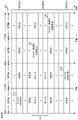
In some wireless communication networks, such as LTE networks, both Frequency Division Duplex (FDD) and Time Division Duplex (TDD) frame structures are supported. For TDD, 7 possible DL and UL subframe configurations are supported, as shown in fig. 7. It can be noted that there are 2 switching periods, 5ms and 10 ms. For 5ms, there are two special subframes in one frame (10ms), as shown in fig. 8. For 10ms, there is one special subframe in one frame. The present methods and apparatus may be employed when supporting a larger or smaller number of subframe configurations.
In LTE Rel-12, it is possible to dynamically adapt TDD DL/UL subframe configurations based on actual traffic needs, also known as evolved interference management (eIMTA) for traffic adaptation. For example, if a large data burst on the downlink is required during a short duration, the subframe configuration may be changed, e.g., from configuration #1(6 DL: 4 UL) to configuration #5(9 DL: 1 UL). In some cases, it is desirable that the adaptation of the TDD configuration is not slower than 640 ms. In extreme cases, it may be desirable for the adaptation to change as fast as 10ms, although this may not be desirable.
However, in certain aspects, when two or more cells have different downlink and uplink subframes, the adaptation change may cause significant interference to both the downlink and uplink. In addition, the adaptation may cause some complexity of DL and UL HARQ timing management. In certain aspects, each of the seven DL/UL subframe configurations typically has its own DL/UL HARQ timing. DL/UL HARQ timing is optimized for each configuration (e.g., in terms of HARQ operating efficiency). For example, the timing from the PDSCH to the corresponding ACK/NAK may be different for different TDD DL/UL subframe configurations (e.g., depending on when the next available uplink subframe occurs for transmitting the ACK/NAK).
Dynamic switching between seven configurations (or even more if more flexible adaptation changes are deemed necessary) implies that there may be missed ACK/NAK transmission opportunities for some of the DL or UL transmissions if the current DL/UL HARQ timing is maintained.
In certain aspects, to simplify operations for enhanced (or evolved) interference mitigation with traffic adaptation changes (eIMTA), it is possible to define a single DL/UL configuration as a reference for many physical layer operations. For example, the DL HARQ operation may be based on DL/UL subframe configuration # 5 regardless of an actual DL/UL subframe configuration used in one frame (or half of a frame).
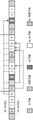
That is, if dynamic DL/UL subframe configuration is enabled, the DL HARQ timing may always be based on a 9:1 DL/UL subframe configuration. Similarly, the UL HARQ operation may be based on, for example, DL/UL subframe configuration # 0, regardless of the actual DL/UL subframe configuration used in one frame (or half of a frame). That is, if dynamic DL/UL subframe configuration is enabled, the UL HARQ timing may always be based on a 4:6 DL/UL subframe configuration, as shown in fig. 9.
As shown in fig. 9, the actual use of the sub-frame may be subject to eNB scheduling. For example, subframe 3/4/5/7/8/9 may be a DL subframe or a UL subframe, while subframe 6 may be a DL subframe or a special subframe.
Enabling common (e) PDCCH to dynamically indicate TDD DL/UL subframe configuration
Aspects of the present disclosure discuss techniques for dynamically indicating a TDD UL/DL subframe configuration to a UE. In certain aspects, a common PDCCH or ePDCCH (enhanced PDCCH) that can be interpreted by multiple UEs may be used to indicate a TDD DL/UL configuration to one or more UEs.
In certain aspects, a common PDCCH (or ePDCCH) is typically associated with a common search space that carries DCI (downlink control information) that is common to multiple UEs. In one aspect, each PDCCH carries one DCI and is identified by an RNTI (radio network temporary identifier) that is implicitly encoded in the CRC attachment portion of the DCI.
In certain aspects, a dynamic indication of TDD DL/UL subframe configuration is desired only for UEs in an RRC _ CONNECTED (RRC _ CONNECTED) state. Thus, in certain aspects, dynamic indication via the common PDCCH may be achieved via a common RNTI (e.g., DTC (dynamic TDD DL/UL configuration) -RNTI). In one aspect, the selection of the 16-bit DTC-RNTI may follow the same principles as C-RNTI (cell-RNTI), and avoid RNTIs used by P-RNTI, SI-RNTI, RA-RNTI, TPC RNTI, and the like. In an aspect, a corresponding PDCCH CRC (cyclic redundancy check) may be scrambled by DTC-RNTI.
In certain aspects, the size of the common PDCCH may match an existing DCI format or may be a new format. For example, the size of the common PDCCH may be small or similar to the size of DCI format 1C. In one aspect, the common PDCCH may include: 3 bits indicating configuration, 5 bits reserved, CRC of 16 bits, a total of 24 bits, which is the same size as DCI format 1C based on 1.4MHz or 6RB system bandwidth. In an aspect, the size of the common PDCCH may be bandwidth independent. Hereinafter, the DCI format for the common PDCCH will be referred to as DCI format 5.
Aspects of the present disclosure relate to anchor subframe based design. Returning to the TDD configuration of fig. 7, four of the subframes are aligned (i.e., subframes 0, 1,2, and 5) between all subframes. In addition, in subframe 6, downlink transmissions are locally aligned. Aligned subframes (i.e., subframes that do not change between configurations) may also be referred to as anchor subframes. Thus, the anchor subframes may include subframes 0, 1,2, and 5. Further, subframe 6 may be considered an anchor subframe because downlink transmissions are locally aligned. Non-aligned subframes (i.e., subframes that change between different configurations) may be referred to as non-anchor subframes.
In certain aspects, adaptive TDD configurations may be improved based on anchor subframes. In certain aspects, the common PDCCH may be carried only in DL anchor subframes, but may not need to be carried in all DL anchor subframes.
In certain aspects, a common PDCCH indicating a TDD DL/UL subframe configuration may be transmitted in an early subframe of a frame, or even earlier (e.g., in a previous frame), to allow both the eNB and the UE to react to the new configuration. For example, to give the UE sufficient time to decode the common PDCCH and determine the TDD UL/DL subframe configuration. Fig. 10 shows transmission of a common PDCCH indicating TDD DL/UL subframe configuration for frame n in subframe 5 of frame n-1.
In certain aspects, the set of subframes for the UE to monitor DCI format 5 may be predetermined or indicated by signaling (e.g., broadcast or unicast). For example, subframe 5 of all frames may be predetermined to carry a common PDCCH. In an aspect, one of the SIBs may indicate which subframes/frames carry DCI format 5. In an aspect, dedicated signaling may be used to indicate which subframes/frames carry DCI format 5. In certain aspects, the same subframe configuration indication may be transmitted in multiple subframes. The UE may monitor multiple subframes for the same TDD DL/UL subframe configuration indication to facilitate eNB control of load balancing and Discontinuous Reception (DRX) operation for the UE. For example, the UE may monitor the common PDCCH in both subframes 5 and 6.
In certain aspects, different UEs may have different DRX operations. For example, since DRX operation is subframe-specific, a UE1 may monitor subframe 5 and another UE2 may monitor subframe 6. Thus, in an aspect, the set of subframes for the UE to monitor DCI format 5 may be associated with its DRX operation. This may for example ensure that there is at least one subframe carrying DCI format 5 within a certain duration. In an aspect, the UE may need to wake up in advance to monitor DCI format 5 before the ON duration (especially during long DRX). In an aspect, if the UE cannot detect the common PDCCH, it may fall back to the legacy configuration or the reference configuration.
In certain aspects, the eNB may consider transmitting a common PDCCH in at least two DL anchor subframes to increase reliability. From the UE perspective, it may monitor the common PDCCH in at least two DL subframes, and may also combine the two DL subframes for joint decoding (TTI bundling for PDCCH) for more time diversity. For example, there may be 2 level (level 2) PDCCH transmissions in two subframes as compared to one level 4 PDCCH transmission in one subframe.
In an aspect, the reliability of the common PDCCH may be further improved by power control.
In certain aspects, there may be a restriction on the set of available subframes. For example, some subframes may experience interference on UL or DL, and thus the eNB may only use certain subframes (e.g., subframes when an interfering cell is configured with almost blank subframes). As a result, the set of subframes available for use may be limited. Thus, in an aspect, the time location of the common PDCCH may be different for different cells. For example, as shown in fig. 11, cell 1 transmits the common PDCCH using subframe 5, and cell 2 transmits the common PDCCH using subframe 6.
In certain aspects, the UE may not be required to decode DCI format 1C in subframes in which the common PDCCH is transmitted for blind decoding purposes. In one aspect, the set of decoding candidates initially monitored for DCI format 1C may be used for DCI format 5, thus maintaining the same number of blind decodes as DCI format 5. Therefore, a new DCI format may replace DCI format 1C for the UE to use to monitor certain subframes. As a result, the number of DCI sizes to be monitored is not increased.
In certain aspects, to maintain the same number of maximum blind decoding numbers, the number of decoding candidates for DCI format 5 should be the same as the number of decoding candidates for DCI format 1C. However, the set of aggregation levels for DCI format 5 may be modified to be different from the set of aggregation levels for DCI format 1C, which typically has 4 decoding candidates for 4 levels (level 4) and 2 decoding candidates for 8 levels (level 8), for a total of 6 decoding candidates, in order to accommodate DCI format 5. In one aspect, the motivation is that for a payload size of 24 bits, 2 CCEs (or 72 REs) results in a coding rate of 24/2 (QPSK)/72-1/6, which should be sufficient to cover most cases, especially considering the context of small cells. An example set of aggregation levels is {1,2,2,1} for aggregation levels {1,2,4,8}, respectively. That is, we can still support the original aggregation levels 1,2,4,8 for DCI format 5, but to keep the same decoding candidates, the aggregation levels 1,2,2,1 can be used for the aggregation levels 1,2,4, 8.
For DCI format 1C, the common search space always starts from CCE 0. In an aspect, the common search space may also start at CCE 0 for DCI format 5. But this may be limiting as it may conflict with common search space transmissions. That is, for DCI format 5, the starting CCE for each aggregation level may be the same common search space for the same aggregation level, and for other new aggregation levels, the starting CCE for each aggregation level may be within the common search space, but is limiting as this may conflict with common search space related operations (e.g., paging, RAR response, system information broadcast, etc.). As a result, two alternatives can be devised to address this problem.
In a first alternative, the starting CCE may be configured via RRC signaling. The RRC configuration may be aggregation level dependent and/or subframe dependent. The RRC configuration may be common for all UEs of a cell, or may be common for a group of UEs of a cell, but different groups of UEs (two or more groups) for a cell may be different.
In a second alternative, the starting CCE may be derived based on DTC-RNTI (similar to C-RNTI). This method is simple and at the same time effective. Further simplification is possible, for example, the starting CCE for all aggregation levels may be the same (e.g., based on 8 levels).
In certain aspects, dynamic indication of TDD UL/DL subframe configurations may be supported via ePDCCH. In an aspect, the earlier discussion for common PDCCH may be largely applicable to ePDCCH, but with some differences. For example, distributed ePDCCH may be preferred for common EPDCCH DCI format 5. In an aspect, if the UE is configured with two ePDCCH resource sets, it is sufficient to set the common ePDCCH in one resource set. In certain aspects, if a UE is configured with only a local set of ePDCCH resources, a dynamic indication may be transmitted via a certain local ePDCCH.
In certain aspects, the UE may monitor only one of the common PDCCH or the common ePDCCH for a dynamic indication of TDD subframe configuration. Alternatively, if the UE is configured to monitor PDCCH and ePDCCH on different subframes, the UE may monitor both the common PDCCH or the common ePDCCH for a dynamic indication of TDD subframe configuration.
In certain aspects, if DCI format 5 is assumed instead of DCI format 1C, there may be concern of reduced paging opportunities caused by the absence of DCI format 1C in some subframes. In certain aspects, the UE may be allowed to monitor both DCI format 5 and DCI format 1C in the same subframe. In an aspect, the size of DCI format 5 may be the same as or different from the size of DCI format 1C. With the same size, certain bit(s) within the payload may be used to distinguish between format 1C and format 5. However, if the sizes of format 5 and format 1C are different, in order to maintain the same number of blind decodes (or to minimize the total number of blind decodes), it may be considered to split the decoding candidates between format 1C and format 5 in one subframe for the UE to monitor. For example, 3 decoding candidates for format 5 (2 levels 2 and 1 level 4), and 3 decoding candidates for DCI format 1C (2 levels 4 and 1 level 8). In one aspect, there may also be an uneven split of the decoding candidates between the two formats.
In CoMP scenario 4, the macro cell and its associated small cell may have the same PCI. As a result, if the search space for DCI format 5 depends only on PCI, the search space for format 5 may conflict. Thus, in one aspect, differentiation of DCI format 5 for small cells with the same PCI macro cell and their associated should be supported. In an aspect, this may be achieved by non-overlapping DCI format 5 search spaces for macro and small cells, e.g., by configuring different starting CCEs or ECCEs. In an alternative aspect, the same search space may be used, but within each DCI format, an index may be included that identifies small cells within the same cluster with the same PCI (e.g., similar to DCI 3/3 a-based group power control, where each TPC index corresponds to a particular UE). In an aspect, a mapping between the index and the small cell may also be indicated to the UE.
In certain aspects, the DTC-RNTI may be configured in different manners for different small cells having the same PCI. That is, the UE may be required to monitor two or more DTC-RNTIs for the same PCI. The respective search spaces for two or more DTC-RNTIs may be the same or defined separately (e.g., based on each individual DTC-RNTI).
In certain aspects, the common PDCCH or common ePDCCH may also carry an information field identifying one or more frames to which the TDD DL/UL subframe configuration should be applied. For example, the information field may be a 2-bit information field and indicate that the TDD DL/UL subframe configuration should be applied to one of a current frame (N), a next frame (N +1), a frame N +2, or a frame N +3, where the current frame N is a frame in which the common PDCCH or the common ePDCCH is transmitted.
In certain aspects, the common PDCCH or common ePDCCH may also carry an information field identifying the duration for which the TDD DL/UL subframe configuration should be applied. For example, the information field may be a 2-bit information field and indicate that TDD DL/UL subframe configuration should be applied to one of 1,2,4, or 8 subframes starting from a current frame (N), which is a frame in which a common PDCCH or a common ePDCCH is transmitted.
In certain aspects, the applicability of TDD DL/UL subframe configurations conveyed in a common PDCCH or common ePDCCH depends on the subframe index in the frame in which the PDCCH or ePDCCH is sent. For example, if the PDCCH or ePDCCH is sent in the first half of the frame (i.e., subframes 0-4), TDD DL/UL subframe configuration in the control channel may apply to the current frame; if the PDCCH or ePDCCH is transmitted in the second half of the frame (i.e., subframes 5 to 9), the TDD DL/UL subframe configuration in the control channel may be applied to the next frame.
Fig. 12 illustrates example operations 1200 performed by, for example, a Base Station (BS) for dynamic indication of TDD UL/DL subframe configurations in accordance with aspects of the disclosure. At 1202, operations 1200 may begin by identifying one or more anchor subframes and one or more non-anchor subframes in a frame. At 1204, the BS may dynamically change an uplink/downlink configuration of the frame for communicating with the plurality of UEs. At 1206, the BS may transmit the changed configuration using a common downlink control channel capable of being interpreted by the plurality of UEs in at least one of the one or more anchor subframes of the frame.
In certain aspects, the size of the common downlink control channel may be the same as that defined for the legacy LTE DCI format. In an aspect, the legacy LTE DCI format may include DCI format 1C. In certain aspects, the size of the common downlink control channel may be independent of the downlink system bandwidth.
In certain aspects, the base station may scramble the CRC code of the common downlink control channel with the RNTI specific to the common downlink control channel. In certain aspects, a base station may configure two or more RNTI values for cells having the same Physical Cell Identity (PCI), wherein each UE of a plurality of UEs is instructed to monitor only one RNTI value of the two or more RNTI values.
In certain aspects, the transmitting of the changed configuration may include transmitting the common downlink control channel only in a subset of the one or more anchor subframes of the frame.
In certain aspects, the communicating of the changed configuration may include transmitting a common downlink control channel in one or more anchor subframes of the frame for indicating an uplink/downlink configuration of another subsequent frame.
In certain aspects, the base station may indicate, via explicit signaling, to at least one UE of the plurality of UEs, a set of subframes configured to carry a common downlink control channel. In an aspect, the explicit signaling may include signaling via a System Information Block (SIB). In an aspect, the explicit signaling may include dedicated signaling for the indication. In an aspect, a set of subframes configured to carry a common downlink control channel may be predetermined.
In certain aspects, a base station may determine a set of subframes for carrying a common downlink control channel for each UE based ON DRX operation of the UE such that at least one subframe carries a downlink control channel for a DRX ON duration.
In certain aspects, the transmitting of the changed configuration may include transmitting a common downlink control channel in at least two downlink anchor subframes.
In certain aspects, the temporal location of the subframes carrying the common downlink control channel may be different for different cells.
In certain aspects, the transmitting of the changed configuration may include transmitting the common downlink control channel in a subframe initially configured for transmission of the legacy downlink control channel such that a number of decoding candidates for blind decoding the common downlink control channel is the same as a number of decoding candidates for blind decoding the legacy downlink control channel. In an aspect, in a subframe, transmission of a common downlink control channel may replace transmission of a legacy downlink control channel. In an aspect, the starting CCE of the search spaces used for blind decoding of the common downlink control channel and the legacy downlink control channel may be the same. In an aspect, a starting CCE of a search space for blind decoding of a common downlink control channel may be configured via Radio Resource Control (RRC) signaling. In one aspect, RRC signaling is UE specific. In an aspect, a starting CCE of a search space used for blind decoding of a common downlink control channel may be derived based on a common downlink control channel specific Radio Network Temporary Identifier (RNTI).
In certain aspects, the base station may also transmit the common downlink control channel and the legacy downlink control channel simultaneously in the subframe. In an aspect, the size of the common downlink control channel and the size of the legacy downlink control channel may be the same. In an aspect, a base station may transmit one bit to distinguish between a common downlink control channel and a legacy downlink control channel.
In certain aspects, the uplink/downlink configuration of the subframe may comprise a Time Division Duplex (TDD) uplink-downlink configuration. In certain aspects, the common downlink control channel may comprise PDCCH or ePDCCH.
In certain aspects, the search space for blind decoding of the common downlink control channel may include candidates for at least one of an aggregation level 1, an aggregation level 2, an aggregation level 4, or an aggregation level 8.
In certain aspects, the common downlink control channel may include information regarding one or more frames to which the changed configuration is to be applied. In an aspect, the common downlink control channel may include an information field for carrying information about the one or more frames.
In certain aspects, the common downlink control channel may include information regarding a duration for which the changed configuration is to be applied. In one aspect, the duration may comprise one or more frame lengths. In one aspect, the information may include a starting frame number of a frame from which the changed configuration is to be applied for the duration.
In certain aspects, the application of the changed configuration to one or more frames may be based on a location of transmission of a common downlink control channel within the frame. In an aspect, if the common downlink control channel is transmitted in the first portion of the frame, the changed configuration may be applied to the frame. In an aspect, if the common downlink control channel is transmitted in the second portion of the frame, the changed configuration may be applied to a subsequent frame. In one aspect, the first and second portions of the frame may comprise first and second half frames, respectively.
Fig. 13 illustrates example operations 1300 performed by, for example, a User Equipment (UE) for dynamic indication of TDD UL/DL subframe configuration in accordance with aspects of the disclosure. At 1302, operations 1300 may begin by monitoring one or more anchor subframes of a frame for a common downlink control channel indicating a changed uplink/downlink configuration of subframes for communicating with at least the UE. At 1304, the UE may decode the common downlink control channel to determine a changed uplink/downlink configuration of subframes used in subsequent communications.
In certain aspects, the size of the common downlink control channel may be the same as that defined for the legacy LTE DCI format. In certain aspects, the size of the common downlink control channel may be independent of the downlink system bandwidth. In an aspect, the legacy LTE DCI format may include DCI format 1C.
In certain aspects, the CRC code for the common downlink control channel may be scrambled by the RNTI specific to the common downlink control channel. In certain aspects, two or more RNTI values may be configured for cells having the same Physical Cell Identity (PCI), wherein the UE monitors only one of the two or more RNTI values.
In certain aspects, the indication of the changed configuration may include a common downlink control channel only in a subset of one or more anchor subframes of the frame.
In certain aspects, the indication of the changed configuration may include a common downlink control channel in one or more anchor subframes of a frame indicating an uplink/downlink configuration for another subsequent frame.
In certain aspects, the UE may receive, via explicit signaling, an indication of a set of subframes configured to carry a common downlink control channel. In an aspect, the explicit signaling may include signaling via SIBs. In an aspect, the explicit signaling may include dedicated signaling for the indication. In an aspect, a set of subframes configured to carry a common downlink control channel may be predetermined.
In certain aspects, the set of subframes that carry the common downlink control channel for each UE is based ON DRX operation of the UE such that at least one subframe carries the downlink control channel for a DRX ON duration.
In certain aspects, the indication of the changed configuration may include a common downlink control channel in at least two downlink anchor subframes.
In certain aspects, the temporal location of the subframes carrying the common downlink control channel may be different for different cells.
In certain aspects, the UE may determine one or more frames to apply the changed configuration according to a location of a transmission of a common control channel within the frames. In one aspect, if the common downlink control channel is transmitted in the first portion of the frame, the changed configuration may be applied to the frame itself. In one aspect, the changed configuration may be applied to a subsequent frame if the common downlink control channel is transmitted in a second, different portion of the frame. In one aspect, the first and second portions of the frame may comprise first and second half frames, respectively.
In certain aspects, the UE may determine a duration during which the changed configuration is to be applied based on information sent in a common downlink control channel.
In certain aspects, the indication of the changed uplink/downlink configuration may include the common downlink control channel in a subframe originally configured for transmission of the legacy downlink control channel such that the number of decoding candidates for blind decoding the common downlink control channel is the same as the number of decoding candidates for blind decoding the legacy downlink control channel. In an aspect, in a subframe, a common downlink control channel may replace a legacy downlink control channel. In an aspect, the starting CCE of the search spaces used for blind decoding of the common downlink control channel and the legacy downlink control channel may be the same. In one aspect, a starting CCE of a search space for blind decoding of a common downlink control channel is configured via Radio Resource Control (RRC) signaling. In an aspect, the RRC signaling may be UE specific. In one aspect, a starting CCE of a search space used for blind decoding of a common downlink control channel is derived based on a common downlink control channel specific Radio Network Temporary Identifier (RNTI). In an aspect, a common downlink control channel and a legacy downlink control channel may be received simultaneously in a subframe. In an aspect, the size of the common downlink control channel and the size of the legacy downlink control channel may be the same. In an aspect, the indication of the configuration may include one bit to distinguish between the common downlink control channel and the legacy downlink control channel.
In certain aspects, the uplink/downlink configuration of a subframe may comprise a Time Division Duplex (TDD) uplink-downlink configuration.
In certain aspects, the common downlink control channel comprises a PDCCH or ePDCCH.
In certain aspects, the search space for blind decoding of the common downlink control channel may include candidates for at least one of an aggregation level 1, an aggregation level 2, an aggregation level 4, or an aggregation level 8.
It should be understood that the specific order or hierarchy of steps in the processes disclosed is an illustration of exemplary approaches. It should be understood that the specific order or hierarchy of steps in the processes may be rearranged based on design preferences. In addition, some steps may be combined or omitted. The accompanying method claims present elements of the various steps in a sample order, and are not meant to be limited to the specific order or hierarchy presented.
Furthermore, the term "or" is intended to mean an inclusive "or" rather than an exclusive "or". That is, for example, the phrase "X employs A or B" is intended to mean any of the natural inclusive permutations, unless specified otherwise or clear from the context. That is, for example, any of the following examples satisfies the phrase "X employs a or B": x is A; b is used as X; or X uses both A and B. In addition, the articles "a" and "an" as used in this application and the appended claims should generally be construed to mean "one or more" unless specified otherwise or clear from context to be directed to a singular form. A phrase referring to "at least one of a list of items" refers to any combination of such items, including a single member. For example, "at least one of a, b, or c" is intended to cover: a. b, c, a-b, b-c and a-b-c.
The previous description is provided to enable any person skilled in the art to practice the various aspects described herein. Various modifications to these aspects will be readily apparent to those skilled in the art, and the generic principles defined herein may be applied to other aspects. Thus, the claims are not intended to be limited to the aspects shown herein, but is to be accorded the full scope consistent with the language claims, wherein reference to an element in the singular is not intended to mean "one and only one" unless specifically so stated, but rather "one or more. The term "some" means one or more unless explicitly stated otherwise. All structural and functional equivalents to the elements of the various aspects described throughout this disclosure that are known or later come to be known to those of ordinary skill in the art are expressly incorporated herein by reference and are intended to be encompassed by the claims. Moreover, nothing disclosed herein is intended to be dedicated to the public regardless of whether such disclosure is explicitly recited in the claims. No claim element is to be construed as a functional module unless the element is explicitly recited using the phrase "unit for … …".
Claims (15)
1. A method of wireless communication by a Base Station (BS), comprising:
identifying one or more anchor subframes and one or more non-anchor subframes in a frame;
dynamically changing an uplink/downlink configuration of the frame for communicating with a plurality of User Equipments (UEs); and
transmitting the changed configuration using a common downlink control channel capable of being interpreted by the plurality of UEs in at least one of the one or more anchor subframes of the frame,
wherein the changed configuration is applied to the frame if the common downlink control channel is transmitted in the first portion of the frame; and is
Wherein the changed configuration is applied to a subsequent frame if the common downlink control channel is transmitted in the second portion of the frame.
2. The method of claim 1, wherein a size of the common downlink control channel is the same as a size defined for a legacy Long Term Evolution (LTE) Downlink Control Information (DCI) format.
3. The method of claim 1, further comprising scrambling a Cyclic Redundancy Check (CRC) code of the common downlink control channel with a Radio Network Temporary Identifier (RNTI) specific to the common downlink control channel.
4. The method of claim 1, further comprising configuring two or more RNTI values for cells having a same Physical Cell Identity (PCI), wherein each of the plurality of UEs is indicated to monitor only one of the two or more RNTI values.
5. The method of claim 1, wherein the transmitting comprises transmitting the common downlink control channel in the one or more anchor subframes of the frame for indicating the uplink/downlink configuration for another subsequent frame.
6. The method of claim 1, further comprising indicating, via explicit signaling, to at least one of the plurality of UEs, a set of subframes configured to carry the common downlink control channel.
7. The method of claim 1, further comprising determining a set of subframes for carrying the common downlink control channel for each UE based ON Discontinuous Reception (DRX) operation of the UE such that at least one subframe carries the downlink control channel for a DRX ON duration.
8. A method of wireless communication by a User Equipment (UE), comprising:
monitoring one or more anchor subframes of a frame for a common downlink control channel, wherein the common downlink control channel indicates a changed uplink/downlink configuration of subframes used for communicating with at least the UE; and
decoding the common downlink control channel to determine the changed uplink/downlink configuration of subframes used in subsequent communications,
wherein the changed configuration is applied to the frame if the common downlink control channel is transmitted in the first portion of the frame; and is
Wherein the changed configuration is applied to a subsequent frame if the common downlink control channel is transmitted in the second portion of the frame.
9. The method of claim 8, wherein a size of the common downlink control channel is the same as a size defined for a legacy Long Term Evolution (LTE) Downlink Control Information (DCI) format.
10. The method of claim 8, wherein a Cyclic Redundancy Check (CRC) code of the common downlink control channel is scrambled by a Radio Network Temporary Identifier (RNTI) specific to the common downlink control channel.
11. The method of claim 8, wherein the indication of the changed uplink/downlink configuration comprises the common downlink control channel in the one or more anchor subframes of the frame indicating an uplink/downlink configuration for another subsequent frame.
12. The method of claim 8, further comprising receiving, via explicit signaling, an indication of a set of subframes configured to carry the common downlink control channel.
13. The method of claim 8, wherein a set of subframes carrying the common downlink control channel for each UE is based ON a Discontinuous Reception (DRX) operation of the UE such that at least one subframe carries the downlink control channel for a DRX ON duration.
14. An apparatus for wireless communications by a Base Station (BS), comprising:
means for identifying one or more anchor subframes and one or more non-anchor subframes in a frame;
means for dynamically changing an uplink/downlink configuration of the frame for communicating with a plurality of User Equipments (UEs); and
means for transmitting the changed configuration using a common downlink control channel capable of being interpreted by the plurality of UEs in at least one of the one or more anchor subframes of the frame,
wherein the changed configuration is applied to the frame if the common downlink control channel is transmitted in the first portion of the frame; and is
Wherein the changed configuration is applied to a subsequent frame if the common downlink control channel is transmitted in the second portion of the frame.
15. An apparatus for wireless communications by a User Equipment (UE), comprising:
means for monitoring one or more anchor subframes of a frame for a common downlink control channel indicating changed uplink/downlink configurations of subframes used for communicating with at least the UE; and
means for decoding the common downlink control channel to determine the changed uplink/downlink configuration of subframes used in subsequent communications,
wherein the changed configuration is applied to the frame if the common downlink control channel is transmitted in the first portion of the frame; and is
Wherein the changed configuration is applied to a subsequent frame if the common downlink control channel is transmitted in the second portion of the frame.
Applications Claiming Priority (6)
| Application Number | Priority Date | Filing Date | Title |
|---|---|---|---|
| CNPCT/CN2013/080330 | 2013-07-29 | ||
| PCT/CN2013/080330 WO2015013862A1 (en) | 2013-07-29 | 2013-07-29 | Dynamic indication of time division (tdd) duplex uplink/downlink subframe configurations |
| PCT/CN2013/081188 WO2015013993A1 (en) | 2013-07-29 | 2013-08-09 | Dynamic indication of time division (tdd) duplex uplink/downlink subframe configurations |
| CNPCT/CN2013/081188 | 2013-08-09 | ||
| CN201480042170.4A CN105409310B (en) | 2013-07-29 | 2014-07-14 | The dynamic instruction of time division duplex (TDD) uplink/downlink sub-frame configuration |
| PCT/CN2014/082118 WO2015014207A1 (en) | 2013-07-29 | 2014-07-14 | Dynamic indication of time division duplex (tdd) uplink/downlink subframe configurations |
Related Parent Applications (1)
| Application Number | Title | Priority Date | Filing Date |
|---|---|---|---|
| CN201480042170.4A Division CN105409310B (en) | 2013-07-29 | 2014-07-14 | The dynamic instruction of time division duplex (TDD) uplink/downlink sub-frame configuration |
Publications (2)
| Publication Number | Publication Date |
|---|---|
| CN110635888A CN110635888A (en) | 2019-12-31 |
| CN110635888B true CN110635888B (en) | 2022-08-23 |
Family
ID=52430812
Family Applications (2)
| Application Number | Title | Priority Date | Filing Date |
|---|---|---|---|
| CN201480042170.4A Active CN105409310B (en) | 2013-07-29 | 2014-07-14 | The dynamic instruction of time division duplex (TDD) uplink/downlink sub-frame configuration |
| CN201910966550.1A Active CN110635888B (en) | 2013-07-29 | 2014-07-14 | Dynamic indication of Time Division Duplex (TDD) uplink/downlink subframe configuration |
Family Applications Before (1)
| Application Number | Title | Priority Date | Filing Date |
|---|---|---|---|
| CN201480042170.4A Active CN105409310B (en) | 2013-07-29 | 2014-07-14 | The dynamic instruction of time division duplex (TDD) uplink/downlink sub-frame configuration |
Country Status (20)
| Country | Link |
|---|---|
| US (1) | US10244518B2 (en) |
| EP (1) | EP3028516B1 (en) |
| JP (1) | JP6549117B2 (en) |
| KR (1) | KR102231185B1 (en) |
| CN (2) | CN105409310B (en) |
| AU (2) | AU2014299129A1 (en) |
| CA (1) | CA2917428C (en) |
| CL (1) | CL2016000347A1 (en) |
| ES (1) | ES2953707T3 (en) |
| HK (1) | HK1222081A1 (en) |
| IL (1) | IL243158B (en) |
| MX (1) | MX360406B (en) |
| MY (1) | MY179622A (en) |
| PH (1) | PH12016500014B1 (en) |
| PL (1) | PL3028516T3 (en) |
| RU (1) | RU2663815C2 (en) |
| SA (1) | SA516370483B1 (en) |
| SG (1) | SG11201510320QA (en) |
| WO (3) | WO2015013862A1 (en) |
| ZA (1) | ZA201600950B (en) |
Families Citing this family (30)
| Publication number | Priority date | Publication date | Assignee | Title |
|---|---|---|---|---|
| US20150089382A1 (en) | 2013-09-26 | 2015-03-26 | Wu-chi Feng | Application context migration framework and protocol |
| US20150195056A1 (en) * | 2014-01-06 | 2015-07-09 | Intel IP Corporation | Systems, methods, and devices to support a fast tdd configuration indication |
| US10123323B2 (en) * | 2014-10-24 | 2018-11-06 | Qualcomm Incorporated | Dynamic uplink/downlink frame structure for enhanced component carriers |
| KR101922250B1 (en) | 2015-07-17 | 2018-11-26 | 주식회사 케이티 | Method allocating resources for subframe and communication apparatus |
| WO2017031642A1 (en) * | 2015-08-21 | 2017-03-02 | 华为技术有限公司 | Data communication method and apparatus |
| WO2017052326A1 (en) * | 2015-09-24 | 2017-03-30 | Lg Electronics Inc. | Method and apparatus for handling various iot network access in wireless communication system |
| CN107294684B (en) * | 2016-04-01 | 2021-07-09 | 夏普株式会社 | Method and base station for configuring non-anchor physical resource block, method for determining position of non-anchor physical resource block and user equipment |
| US10368329B2 (en) | 2016-04-11 | 2019-07-30 | Qualcomm Incorporated | Synchronization for standalone LTE broadcast |
| US10631331B2 (en) * | 2016-04-22 | 2020-04-21 | Qualcomm Incorporated | Frame structure signaling for multefire |
| CN107465495B (en) * | 2016-06-03 | 2020-08-28 | 北京佰才邦技术有限公司 | Indication method and device of transmission state |
| WO2017213222A1 (en) * | 2016-06-10 | 2017-12-14 | 株式会社Nttドコモ | User terminal and radio communication method |
| DE112018000687T5 (en) * | 2017-02-03 | 2019-10-24 | Intel IP Corporation | FRAME STRUCTURE FOR UNLICENSED INTERNET OF THINGS |
| DK3592061T3 (en) * | 2017-03-02 | 2021-12-06 | Ntt Docomo Inc | USER TERMINAL AND WIRELESS COMMUNICATION PROCEDURE |
| EP4114119A1 (en) * | 2017-03-07 | 2023-01-04 | Apple Inc. | Monitoring control channels in control resource sets for new radio |
| AU2017403690B2 (en) * | 2017-03-16 | 2021-01-28 | Huawei Technologies Co., Ltd. | Transmission direction configuration method, device, and system |
| EP3606279A4 (en) * | 2017-04-18 | 2020-04-08 | Huawei Technologies Co., Ltd. | Method and device for indicating subframe configuration |
| US10659151B2 (en) | 2017-04-21 | 2020-05-19 | Apple Inc. | Apparatus, system and method for utilizing a flexible slot format indicator |
| US10673605B2 (en) | 2017-06-15 | 2020-06-02 | Apple Inc. | Semi-static and dynamic TDD configuration for 5G-NR |
| CN109391422B (en) | 2017-08-11 | 2020-11-17 | 华为技术有限公司 | Method for determining feedback codebook, terminal equipment and network equipment |
| CN111201743B (en) * | 2017-08-11 | 2022-09-02 | 瑞典爱立信有限公司 | Common control signaling for efficient system operation |
| US10687324B2 (en) * | 2017-10-02 | 2020-06-16 | Telefonaktiebolaget Lm Ericsson (Publ) | PDCCH monitoring periodicity |
| EP4099607B1 (en) | 2017-10-02 | 2023-12-27 | Telefonaktiebolaget LM Ericsson (publ) | Pdcch monitoring periodicity |
| CN111183704B (en) * | 2017-10-02 | 2023-05-30 | 瑞典爱立信有限公司 | Configuring random access channels for wireless communications |
| US10707915B2 (en) * | 2017-12-04 | 2020-07-07 | Qualcomm Incorporated | Narrowband frequency hopping mechanisms to overcome bandwidth restrictions in the unlicensed frequency spectrum |
| CN109688627B (en) * | 2018-03-29 | 2022-05-10 | 新华三技术有限公司 | Wireless resource scheduling method, network side equipment and user equipment |
| CN109076558B (en) * | 2018-07-06 | 2022-12-06 | 北京小米移动软件有限公司 | Method and device for identifying downlink transmission |
| CN110740025B (en) * | 2018-07-20 | 2021-03-02 | 维沃移动通信有限公司 | Channel detection indication method, terminal and network equipment |
| EP3909396B1 (en) | 2019-01-11 | 2022-09-28 | Telefonaktiebolaget Lm Ericsson (Publ) | Inter-node coordination for cross-link interference management |
| WO2022147826A1 (en) * | 2021-01-11 | 2022-07-14 | Lenovo (Beijing) Limited | Method and apparatus for uplink transmission |
| CN116636178A (en) * | 2021-12-20 | 2023-08-22 | 北京小米移动软件有限公司 | Uplink transmission indication, determination method and device, communication device and storage medium |
Citations (2)
| Publication number | Priority date | Publication date | Assignee | Title |
|---|---|---|---|---|
| CN102845012A (en) * | 2010-03-29 | 2012-12-26 | 三星电子株式会社 | Method and system for uplink acknowledgement signaling in carrier-aggregated wireless communication systems |
| CN103023614A (en) * | 2012-12-24 | 2013-04-03 | 新邮通信设备有限公司 | Method for dynamically configuring uplink and downlink subframe proportion of TDD (time division duplex) base station based on business load |
Family Cites Families (18)
| Publication number | Priority date | Publication date | Assignee | Title |
|---|---|---|---|---|
| JP4814176B2 (en) | 2007-05-01 | 2011-11-16 | 株式会社エヌ・ティ・ティ・ドコモ | Base station apparatus and synchronization channel transmission method |
| US20130016841A1 (en) * | 2009-09-25 | 2013-01-17 | Mo-Han Fong | System and Method for Multi-Carrier Network Operation |
| IL288647B2 (en) * | 2009-11-30 | 2023-12-01 | Pluri Biotech Ltd | Adherent Cells From Placenta And Use Of Same In Treating Heart Failure |
| US9240510B2 (en) * | 2009-12-07 | 2016-01-19 | Electrotherm, Inc. | Concentrated photovoltaic and thermal solar energy collector |
| CN102594438B (en) * | 2011-01-13 | 2017-03-15 | 中兴通讯股份有限公司 | Data transmission method, apparatus and system |
| WO2012113131A1 (en) | 2011-02-21 | 2012-08-30 | Renesas Mobile Corporation | Dynamic uplink/downlink configuration for time division duplex |
| US9432982B2 (en) * | 2011-04-27 | 2016-08-30 | Lg Electronics Inc. | Method and apparatus for transmitting control information in wireless communication system |
| KR102031031B1 (en) * | 2011-06-20 | 2019-10-15 | 삼성전자 주식회사 | Method and apparatus for transmitting and receiving time division duplex frame configuration information in wireless communication system |
| US20130027217A1 (en) * | 2011-07-29 | 2013-01-31 | General Electric Company | Systems, Methods, and Apparatus for Automatically Configuring a Utility Meter |
| US8705556B2 (en) * | 2011-08-15 | 2014-04-22 | Blackberry Limited | Notifying a UL/DL configuration in LTE TDD systems |
| US8923274B2 (en) | 2011-08-15 | 2014-12-30 | Blackberry Limited | Notifying a UL/DL configuration in LTE TDD systems |
| EP2807860A4 (en) | 2012-01-23 | 2016-04-13 | Intel Corp | Network assisted user association and offloading techniques for integrated multi-rat heterogeneous networks |
| US9143984B2 (en) | 2012-04-13 | 2015-09-22 | Intel Corporation | Mapping of enhanced physical downlink control channels in a wireless communication network |
| US9642148B2 (en) * | 2012-05-01 | 2017-05-02 | Qualcomm Incorporated | Interference cancellation based on adaptive time division duplexing (TDD) configurations |
| WO2014043863A1 (en) * | 2012-09-19 | 2014-03-27 | Qualcomm Incorporated | Method and apparatus for separating a cell cluster for lte eimta interference mitigation |
| WO2014049169A1 (en) | 2012-09-28 | 2014-04-03 | Nokia Siemens Networks Oy | Timing indication for dynamic time division duplex (tdd) uplink/downlink (ul/dl) reconfiguration |
| US9191930B2 (en) * | 2013-03-13 | 2015-11-17 | Samsung Electronics Co., Ltd. | Transmission of acknowledgement information in adaptively configured TDD communication systems |
| US9474089B2 (en) * | 2013-10-22 | 2016-10-18 | Acer Incorporated | User equipment and base station with configurable carrier |
-
2013
- 2013-07-29 WO PCT/CN2013/080330 patent/WO2015013862A1/en active Application Filing
- 2013-08-09 WO PCT/CN2013/081188 patent/WO2015013993A1/en active Application Filing
-
2014
- 2014-07-14 PL PL14832594.7T patent/PL3028516T3/en unknown
- 2014-07-14 KR KR1020167005164A patent/KR102231185B1/en active IP Right Grant
- 2014-07-14 AU AU2014299129A patent/AU2014299129A1/en not_active Abandoned
- 2014-07-14 SG SG11201510320QA patent/SG11201510320QA/en unknown
- 2014-07-14 ES ES14832594T patent/ES2953707T3/en active Active
- 2014-07-14 CA CA2917428A patent/CA2917428C/en active Active
- 2014-07-14 WO PCT/CN2014/082118 patent/WO2015014207A1/en active Application Filing
- 2014-07-14 US US14/905,929 patent/US10244518B2/en active Active
- 2014-07-14 MY MYPI2015704661A patent/MY179622A/en unknown
- 2014-07-14 RU RU2016102610A patent/RU2663815C2/en active
- 2014-07-14 JP JP2016530323A patent/JP6549117B2/en active Active
- 2014-07-14 MX MX2016001175A patent/MX360406B/en active IP Right Grant
- 2014-07-14 EP EP14832594.7A patent/EP3028516B1/en active Active
- 2014-07-14 CN CN201480042170.4A patent/CN105409310B/en active Active
- 2014-07-14 CN CN201910966550.1A patent/CN110635888B/en active Active
-
2015
- 2015-12-23 IL IL243158A patent/IL243158B/en active IP Right Grant
-
2016
- 2016-01-04 PH PH12016500014A patent/PH12016500014B1/en unknown
- 2016-01-27 SA SA516370483A patent/SA516370483B1/en unknown
- 2016-02-11 ZA ZA2016/00950A patent/ZA201600950B/en unknown
- 2016-02-12 CL CL2016000347A patent/CL2016000347A1/en unknown
- 2016-08-25 HK HK16110144.6A patent/HK1222081A1/en unknown
-
2018
- 2018-09-11 AU AU2018229417A patent/AU2018229417B2/en active Active
Patent Citations (2)
| Publication number | Priority date | Publication date | Assignee | Title |
|---|---|---|---|---|
| CN102845012A (en) * | 2010-03-29 | 2012-12-26 | 三星电子株式会社 | Method and system for uplink acknowledgement signaling in carrier-aggregated wireless communication systems |
| CN103023614A (en) * | 2012-12-24 | 2013-04-03 | 新邮通信设备有限公司 | Method for dynamically configuring uplink and downlink subframe proportion of TDD (time division duplex) base station based on business load |
Non-Patent Citations (2)
| Title |
|---|
| Discussion on Differences in Behaviors between Fixed and Flexible Subframes;MediaTek Inc.;《3GPP TSG-RAN WG1 Meeting #73 R1-132274》;20130524;第1-2节 * |
| Signalling Mechanisms for TDD UL-DL Reconfiguration;Qualcomm Incorporated;《3GPP TSG-RAN WG1 #73 R1-132488》;20130524;第1-3节 * |
Also Published As
Similar Documents
| Publication | Publication Date | Title |
|---|---|---|
| AU2018229417B2 (en) | Dynamic indication of time division duplex (tdd) uplink/downlink subframe configurations | |
| US10200985B2 (en) | Methods and apparatus for managing control and data transmissions for low cost user equipments | |
| CN107852316B (en) | Method, apparatus and medium for encoding and multiplexing downlink control information of same aggregation level | |
| KR101891908B1 (en) | SEMI-PERSISTENT SCHEDULING FOR eIMTA IN LTE | |
| CN109155692B (en) | Wireless communication method, apparatus and readable medium by user equipment | |
| CN107104773B (en) | Adaptive control channel design for balancing data payload size and decoding time | |
| US9641310B2 (en) | Network assisted interference cancellation signaling | |
| KR102544306B1 (en) | Methods and apparatus for managing code block interleaving | |
| EP2984777A1 (en) | Methods and apparatus for employing multiple subframe configurations for harq operations | |
| EP2904863B1 (en) | Processing pmch / prs and epdcch in lte | |
| NZ716842B2 (en) | Dynamic indication of time division duplex (tdd) uplink/downlink subframe configurations |
Legal Events
| Date | Code | Title | Description |
|---|---|---|---|
| PB01 | Publication | ||
| PB01 | Publication | ||
| SE01 | Entry into force of request for substantive examination | ||
| SE01 | Entry into force of request for substantive examination | ||
| REG | Reference to a national code |
Ref country code: HK Ref legal event code: DE Ref document number: 40018284 Country of ref document: HK |
|
| GR01 | Patent grant | ||
| GR01 | Patent grant |