Disclosure of Invention
The invention provides an electric swinging nozzle type small commutator and a water flow calibrating device with the same, which can solve the technical problems of large commutator reversing time difference, non-uniform nozzle jet, water splashing, water distributor overflow, water droplet hanging and the like in small flow calibration caused by different reversing stress, asymmetrical commutator reversing position and the like due to processing and manufacturing reasons in the prior art, and improve the accuracy of the water flow calibrating device.
According to an aspect of the present invention, there is provided an electrically oscillating nozzle type compact commutator, including: a tubular shaft having an internal through-hole with an aperture of

The pipe shaft is connected with a pipeline of the water flow calibration device and is used for introducing water flow in the water flow calibration device; the swinging nozzle assembly is rotatably connected with the tubular shaft; first electromagnetic assembly and second electromagnetic assembly, first electromagnetic assembly and second electromagnetic assembly set up for swing nozzle assembly symmetry, and first electromagnetic assembly is connected with swing nozzle assembly's one end, and the second electromagnetic assembly is connected with swing nozzle assembly's the other end, and first electromagnetic assembly is used for driving swing nozzle assembly and rotates around first direction for the tubular shaft, and second electromagnetic assembly is usedThe swinging nozzle assembly is driven to rotate around a second direction relative to the pipe shaft; the first adjustable assembly is arranged between the first electromagnetic assembly and one end of the swing nozzle assembly, the second adjustable assembly is arranged between the second electromagnetic assembly and the other end of the swing nozzle assembly, the first adjustable assembly is used for adjusting the rotation angle of the swing nozzle assembly around the first direction relative to the tubular shaft, and the second adjustable assembly is used for adjusting the rotation angle of the swing nozzle assembly around the second direction relative to the tubular shaft; the water knockout drum, the water knockout drum includes first water pipeline and second water pipeline, when the swing nozzle subassembly rotates around first direction for the tubular shaft, the swing nozzle subassembly is linked together with the second water pipeline, when the swing nozzle subassembly rotates around the second direction for the tubular shaft, the swing nozzle subassembly is linked together with first water pipeline.
Furthermore, the first adjustable assembly comprises a first adjusting ring and a second adjusting ring, the first adjusting ring and the second adjusting ring are in threaded fit connection, the first adjusting ring is rotatably connected with one end of the swing nozzle assembly, the second adjusting ring is rotatably connected with the first electromagnetic assembly, and the miniature commutator is used for adjusting the rotation angle of the swing nozzle assembly relative to the pipe shaft around the first direction by changing the length of the threaded fit of the first adjusting ring and the second adjusting ring; the second adjustable assembly comprises a third adjusting ring and a fourth adjusting ring, the third adjusting ring is in threaded fit connection with the fourth adjusting ring, the third adjusting ring is in rotatable connection with the other end of the swing nozzle assembly, the fourth adjusting ring is in rotatable connection with the second electromagnetic assembly, and the small commutator adjusts the rotation angle of the swing nozzle assembly around the second direction relative to the tubular shaft by changing the length of the threaded fit of the third adjusting ring and the fourth adjusting ring.
Furthermore, the first adjustable assembly also comprises a first fixing nut, the first fixing nut is arranged between the first adjusting ring and the second adjusting ring, and the first fixing nut is used for fixing the first adjusting ring and the second adjusting ring; the second adjustable assembly further comprises a second fixing nut disposed between the third adjusting ring and the fourth adjusting ring, the second fixing nut being used to fix the third adjusting ring and the fourth adjusting ring.
Furthermore, the swinging nozzle assembly comprises a first swinging rod, a second swinging rod, a nozzle shaft sleeve, a nozzle body and a nozzle head, the nozzle shaft sleeve is rotatably sleeved on the tubular shaft, the first swinging rod, the second swinging rod and the nozzle body are fixedly arranged on the outer side of the nozzle shaft sleeve at intervals, the first swinging rod is rotatably connected with the first adjustable assembly, the second swinging rod is rotatably connected with the second adjustable assembly, the nozzle head is arranged in the nozzle body, and the nozzle head is provided with a plurality of water outlet holes.
Further, a plurality of water outlet holes are uniformly arranged in the nozzle head at intervals.
Furthermore, the inner wall of the first water pipeline and the inner wall of the second water pipeline are both subjected to acid washing passivation treatment.
Furthermore, the small commutator of electronic swing nozzle formula still includes signal transmission unit, and signal transmission unit sets up the one end at the swing nozzle subassembly, and signal transmission unit is used for transmitting the signal when the swing nozzle subassembly is linked together with first water pipeline in order to be used for the calibration of discharge.
Further, the signal transmission unit includes a photoelectric switch.
Furthermore, the small commutator of electronic swing nozzle formula still includes the base, and hollow shaft, water knockout drum, first electromagnetic component, photoelectric switch and second electromagnetic component all fix the setting on the base.
According to another aspect of the present invention, there is provided a water flow rate calibration device comprising an electrically oscillating nozzle compact commutator as described above.
By applying the technical scheme of the invention, the distance between the electromagnetic assembly and the swing nozzle swing rod is adjusted by the adjustable assembly, so that the time for the swing nozzle swing rod to rotate left and right around the pipe shaft is adjustable, the time difference of left and right reversing of the commutator is shortened, and the water flow injection angle of the swing nozzle assembly is adjustable, and the mode greatly improves the accuracy of the water flow calibrating device in the aspect of calibrating small flow meters (particularly flow meters with pipe diameters of DN4 mm-DN 6 mm).
Detailed Description
It should be noted that the embodiments and features of the embodiments in the present application may be combined with each other without conflict. The technical solutions in the embodiments of the present invention will be clearly and completely described below with reference to the drawings in the embodiments of the present invention, and it is obvious that the described embodiments are only a part of the embodiments of the present invention, and not all of the embodiments. The following description of at least one exemplary embodiment is merely illustrative in nature and is in no way intended to limit the invention, its application, or uses. All other embodiments, which can be derived by a person skilled in the art from the embodiments given herein without making any creative effort, shall fall within the protection scope of the present invention.
It is noted that the terminology used herein is for the purpose of describing particular embodiments only and is not intended to be limiting of example embodiments according to the present application. As used herein, the singular forms "a", "an" and "the" are intended to include the plural forms as well, and it should be understood that when the terms "comprises" and/or "comprising" are used in this specification, they specify the presence of stated features, steps, operations, devices, components, and/or combinations thereof, unless the context clearly indicates otherwise.
The relative arrangement of the components and steps, the numerical expressions and numerical values set forth in these embodiments do not limit the scope of the present invention unless specifically stated otherwise. Meanwhile, it should be understood that the sizes of the respective portions shown in the drawings are not drawn in an actual proportional relationship for the convenience of description. Techniques, methods, and apparatus known to those of ordinary skill in the relevant art may not be discussed in detail but are intended to be part of the specification where appropriate. In all examples shown and discussed herein, any particular value should be construed as merely illustrative, and not limiting. Thus, other examples of the exemplary embodiments may have different values. It should be noted that: like reference numbers and letters refer to like items in the following figures, and thus, once an item is defined in one figure, further discussion thereof is not required in subsequent figures.
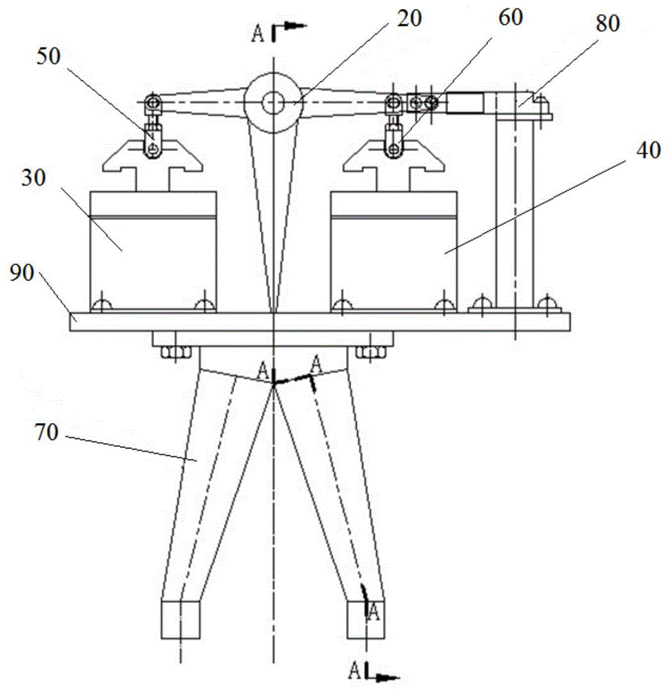
As shown in fig. 1 to 9, according to an embodiment of the present invention, there is provided an electric swing nozzle type compact commutator including a tube shaft 10, a swing nozzle assembly 20, a first solenoid assembly 30, a second solenoid assembly 40, a first adjustable assembly 50, a second adjustable assembly 60, and a water separator 70, wherein the tube shaft 10 has an inner through-hole 10a, and the through-hole 10a has a diameter of

The pipe shaft 10 is connected with a pipeline of the water flow calibration device, and the pipe shaft 10 is used for introducing water flow in the water flow calibration device; the swing nozzle assembly 20 is rotatably connected to the pipe shaft 10, the first and second solenoid assemblies 30 and 40 are symmetrically disposed with respect to the swing nozzle assembly 20, the first solenoid assembly 30 is connected to one end of the swing nozzle assembly 20, the second solenoid assembly 40 is connected to the other end of the swing nozzle assembly 20, the first solenoid assembly 30 is used for driving the swing nozzle assembly 20 to rotate around the pipe shaft 10 in a first direction, the second solenoid assembly 40 is used for driving the swing nozzle assembly 20 to rotate around the pipe shaft 10 in a second direction, the first adjustable assembly 50 is disposed between the first solenoid assembly 30 and one end of the swing nozzle assembly 20, the second adjustable assembly 60 is disposed between the second solenoid assembly 40 and the other end of the swing nozzle assembly 20, the first adjustable assembly 50 is used for adjusting a rotation angle of the swing nozzle assembly 20 around the first direction with respect to the pipe shaft 10, the second adjustable assembly 60 is used for adjusting a rotation angle of the swing nozzle assembly 20 around the second direction with respect to the pipe shaft 10, the water separator 70 includes a first water passage pipe 71 and a second water passage pipe 72, and the swing nozzle assembly 20 communicates with the second water passage pipe 72 when the swing nozzle assembly 20 rotates about the tube shaft 10 in the first direction, and the swing nozzle assembly 20 communicates with the first water passage pipe 71 when the swing nozzle assembly 20 rotates about the tube shaft 10 in the second direction.
With this arrangement, the distance between the first electromagnetic assembly 30 and the oscillating nozzle assembly 20 is adjusted by the first adjustable assembly 50 to change the rotation angle of the oscillating nozzle assembly 20 about the first direction with respect to the pipe shaft 10, and the distance between the second electromagnetic assembly 40 and the other end of the oscillating nozzle assembly 20 is adjusted by the second adjustable assembly 60 to change the rotation angle of the oscillating nozzle assembly 20 about the second direction with respect to the pipe shaft 10, so as to shorten the time difference between the rotation time of the oscillating nozzle assembly 20 about the first direction with respect to the pipe shaft 10 and the rotation time of the oscillating nozzle assembly 20 about the second direction with respect to the pipe shaft 10, thereby greatly improving the accuracy of the water flow calibration apparatus in calibrating small flow meters (particularly, flow meters with pipe diameters of DN4mm to DN6 mm). Furthermore, the method adjusts the rotation angle of the oscillating nozzle assembly 20 about the first direction relative to the pipe shaft 10 through the first adjustable assembly 50 and adjusts the rotation angle of the oscillating nozzle assembly 20 about the second direction relative to the pipe shaft 10 through the second adjustable assembly 60, so that the water jet spray angle of the oscillating nozzle assembly 20 is adjustable.
Further, as shown in fig. 3, in order to facilitate the adjustment of the distance between the first solenoid assembly 30 and the oscillating nozzle assembly 20, the first adjustable assembly 50 may be configured to include a first adjustable ring 51 and a second adjustable ring 52, the first adjustable ring 51 and the second adjustable ring 52 are in threaded engagement, the first adjustable ring 51 is rotatably connected with one end of the oscillating nozzle assembly 20, the second adjustable ring 52 is rotatably connected with the first solenoid assembly 30, and the miniature commutator adjusts the time for which the oscillating nozzle assembly 20 rotates about the first direction and the spraying angle of the nozzle assembly by changing the length of the threaded engagement of the first adjustable ring 51 and the second adjustable ring 52; to facilitate adjustment of the distance between the second electromagnetic assembly 40 and the other end of the oscillating nozzle assembly 20, the second adjustable assembly 60 may be configured to include a third adjusting ring 61 and a fourth adjusting ring 62, the third adjusting ring 61 and the fourth adjusting ring 62 are in threaded engagement, the third adjusting ring 61 is rotatably connected to the other end of the oscillating nozzle assembly 20, the fourth adjusting ring 62 is rotatably connected to the second electromagnetic assembly 40, and the mini-commutator adjusts the rotation time of the oscillating nozzle assembly 20 relative to the tube shaft 10 about the second direction and the spray angle of the nozzle assembly by changing the length of the threaded engagement of the third adjusting ring 61 and the fourth adjusting ring 62.
With this arrangement, when the rotation time about the first direction is longer than the rotation time about the second direction, the difference between the rotation time about the first direction and the rotation time about the second direction of the nozzle assembly 20 relative to the tube shaft 10 is reduced by decreasing the length of the threaded engagement of the first adjustment ring 51 and the second adjustment ring 52 or by increasing the length of the threaded engagement of the third adjustment ring 61 and the fourth adjustment ring 62. When the time of rotation in the first direction is shorter than the time of rotation in the second direction, the difference between the time of rotation in the first direction and the time of rotation in the second direction of the nozzle assembly 20 relative to the tube shaft 10 is reduced by increasing the length of the threaded engagement of the first adjustment ring 51 and the second adjustment ring 52 or by decreasing the length of the threaded engagement of the third adjustment ring 61 and the fourth adjustment ring 62. Furthermore, the method can realize the adjustment of the water jet angle of the swing nozzle assembly 20, and when the length of the threaded fit of the first adjusting ring 51 and the second adjusting ring 52 and the length of the threaded fit of the third adjusting ring 61 and the fourth adjusting ring 62 are simultaneously increased or decreased, the adjustment of the water jet angle of the swing nozzle assembly 20 can be realized.
As an embodiment of the present invention, the first direction is counterclockwise, the second direction is clockwise, a first electromagnet can be used as the first electromagnetic assembly 30, a second electromagnet can be used as the second electromagnetic assembly 40, the second adjusting ring 52 and the fourth adjusting ring 62 are respectively pin-connected with the armature of the first electromagnet and the armature of the second electromagnet, and the first adjusting ring 51 and the third adjusting ring 61 are respectively pin-connected with two ends of the nozzle assembly 20. The distance between the armature of the electromagnet and the two ends of the nozzle component can be conveniently adjusted in a threaded connection mode, and the mode is simple and convenient to operate, easy to process and easy to obtain.
Further, as shown in fig. 3, the first adjustable assembly 50 further includes a first fixing nut 53, the first fixing nut 53 being disposed between the first adjusting ring 51 and the second adjusting ring 52, the first fixing nut 53 being used to fix the relative positions of the first adjusting ring 51 and the second adjusting ring 52; the second adjustable assembly 60 further includes a second fixing nut 63, the second fixing nut 63 being disposed between the third adjustment ring 61 and the fourth adjustment ring 62, the second fixing nut 63 being used to fix the third adjustment ring 61 and the fourth adjustment ring 62.
By applying the configuration mode, the first fixing nut 53 is arranged between the first adjusting ring 51 and the second adjusting ring 52, after the distance between the first electromagnetic assembly 30 and one end of the nozzle assembly 20 is adjusted, the first fixing nut 53 is screwed to fix the relative position of the first electromagnetic assembly 30 and one end of the nozzle assembly 20, so that the relative position of the first adjusting ring 51 and the second adjusting ring 52 is not changed in the reversing process of the electric swinging nozzle type miniature commutator; through set up second fixing nut 63 between third adjustable ring 61 and fourth adjustable ring 62, after second electromagnetic assembly 40 and the other end of nozzle subassembly 20 apart from adjusting the completion, screw up second fixing nut 63 and fix the relative position of second electromagnetic assembly 40 and the other end of nozzle subassembly 20, guarantee in the switching-over process of electronic swing nozzle type miniature commutator that the relative position of third adjustable ring 61 and fourth adjustable ring 62 does not change.
In the invention, the relative positions of the first adjusting ring 51 and the second adjusting ring 52 and the relative positions of the third adjusting ring 61 and the fourth adjusting ring 62 are fixed by nuts, so that the adjustment can be conveniently carried out, the stability and the invariability of the reversing time of the electric swinging nozzle type small commutator are ensured when the reversing process is influenced by external forces such as vibration, impact and the like, the high precision of the electric swinging nozzle type small commutator is kept in the using process, the electric swinging nozzle type small commutator can be used for multiple times after being adjusted, the condition that the electric swinging nozzle type small commutator is required to be adjusted before each use is avoided, and the working efficiency of the device is improved by the mode.
Further, as shown in fig. 4, the swing nozzle assembly 20 includes a first swing link 21, a second swing link 22, a nozzle shaft sleeve 23, a nozzle body 24 and a nozzle head 25, the nozzle shaft sleeve 23 is rotatably sleeved on the pipe shaft 10, the first swing link 21, the second swing link 22 and the nozzle body 24 are fixedly disposed at an interval outside the nozzle shaft sleeve 23, the first swing link 21 is rotatably connected with the first adjustable assembly 50, the second swing link 22 is rotatably connected with the second adjustable assembly 60, the nozzle head 25 is disposed in the nozzle body 24, and the nozzle head 25 has a plurality of water outlet holes 25 a.
By applying the configuration mode, the nozzle head 25 is provided with the plurality of water outlet holes 25a, water flow in the nozzle body 24 is guided to flow out through the plurality of water outlet holes 25a, the angle of the water outlet holes 25a is the jet angle of the liquid, the problem that the jet angle of the water flow is changed due to the fact that the nozzle is deformed due to welding stress in the traditional flat nozzle mode is solved, the influence of the welding stress on the nozzle is reduced, and meanwhile, the error caused by splashing and outflow of the liquid is avoided. In one embodiment of the present invention, the nozzle body 24 and the nozzle head 25 are made of stainless steel blocks, and are connected by welding, and the nozzle head 25 is drilled with a through hole. By adopting the method, the consistent water flow injection angle is achieved, the problems of water flow splashing and backflow which are easily caused when the water flow speed is too high and the water flow direction is inconsistent in the traditional square flat mouth swinging nozzle head are avoided, and the circulation capacity of the water flow is improved.
Further, a plurality of water outlet holes 25a are provided at regular intervals in the nozzle head 25. By applying the configuration mode, a uniform small hole form is adopted, and the jet flow uniformity of the nozzle is ensured. As an embodiment of the present invention, the nozzle body 24 and the nozzle head 25 are made of stainless steel blocks, and are connected by welding, and the nozzle head 25 is drilled with uniform through holes. The method can improve the uniformity of water flow jet flow and enhance the flow capacity of water flow.
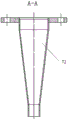
Further, the inner wall of the first water passage 71 and the inner wall of the second water passage 72 are both subjected to pickling and passivation. By applying the configuration mode, the inner walls of the first water pipeline 71 and the second water pipeline 72 of the water separator 70 are subjected to pickling passivation treatment to form oxide films, and water flow forms a layer of water film after circulating on the inner wall of the water separator 70, so that the residual water drop amount on the inner wall of the water separator 70 of the commutator is reduced, and the volume or quality measurement accuracy of the water flow calibrating device is improved.
As a specific embodiment of the invention, the water separator 70 of the small-sized commutator is made of stainless steel, acid pickling passivation paste is coated on the inner wall of the first water pipeline 71 and the inner wall of the second water pipeline 72 of the water separator 70, and after complete reaction, the acid pickling passivation treatment can be completed by flushing with clean water. The method solves the problems that the volume or quality measurement of the water flow device has large random error due to large amount of residual water drops on the inner wall of the water separator 70 and inconsistent amount of the residual water drops in each test, can form a layer of water film after the inner wall of the water separator is treated by an acid pickling and passivation process, prevents the water drops from being residual on the inner wall of the water separator, considers that the thickness of the water film is basically consistent in each test, can change the random error into a system error only by determining the area of the water film residual on the inner wall in one test time, and improves the accuracy of the volume or quality measurement of the water flow calibrating device.
Further, in the present invention, in order to realize signal transmission between the electric swing nozzle type small scale commutator and the water flow rate calibration device, the electric swing nozzle type small scale commutator further includes a signal transmission unit 80, the signal transmission unit 80 is provided at one end of the swing nozzle assembly 20, and the signal transmission unit 80 is used for transmitting a signal for calibration of the water flow rate when the swing nozzle assembly 20 is communicated with the first water passage 71.
With this arrangement, when the water flow calibration device starts calibrating a small flow meter, the second electromagnetic assembly 40 is energized to rotate the oscillating nozzle assembly 20 clockwise with respect to the tubular shaft 10, and water flows toward the first water passage 71 of the water separator, at the same time, the signal transmission unit 80 is triggered to transmit the signal to the water flow calibration device to start timing, when the water flow calibration device obtains a sufficient volume or mass of water, the first solenoid assembly 30 is energized, causing the oscillating nozzle assembly 20 to rotate in a counterclockwise direction with respect to the pipe shaft 10, at the same time, the signal transmission unit 80 is triggered, the signal is transmitted to the water flow calibration device to stop timing, the time difference corresponding to a certain water flow volume or mass flowing through the first water passage of the water separator 70 is thus obtained, and the water flow rate in the pipe can be obtained by taking the quotient of the water volume or mass and the time difference and used for calibrating the small flow meter. The mode can conveniently and quickly measure time, and the timing accuracy in the water flow calibration process is improved.
Further, in the present invention, in order to improve the accuracy of the timing, the signal transmission unit 80 includes a photoelectric switch. By applying the configuration, the signal transmission unit 80 is configured as a photoelectric switch, a shading baffle is arranged at one end of the swing rod, the shading or reflecting state of the light beam of the photoelectric switch is changed when the swing nozzle assembly swings, and the photoelectric switch transmits the signal to the water flow calibration device and records the communication time of the first water pipeline 72 of the swing nozzle assembly. The mode has the advantages of small volume and high response speed, and can greatly improve the timing precision.
Further, in the present invention, in order to provide support for each component and prevent the problem of inaccurate measurement caused by the change of the relative positions of the pipe shaft, the electromagnetic component and the water separator due to external vibration, the electric swing nozzle type small-sized commutator further includes a base 90, and the pipe shaft 10, the water separator 70, the first electromagnetic component 30, the photoelectric switch and the second electromagnetic component 40 are all fixedly disposed on the base 90.
According to another aspect of the present invention, there is provided a water flow rate calibration device including an electrically-operated swinging nozzle type small scale commutator as described above.
By applying the configuration mode, the reversing time difference of the commutator is small, the reversing time difference of the commutator is shortened, the water flow jet angle of the commutator swinging nozzle assembly is adjustable, the jet flow of the commutator nozzle is uniform, the water flow splashing and backflow at the commutator nozzle are avoided, the residual water drop amount on the inner wall of the small commutator water separator 70 is reduced, and the measurement precision of the water flow calibration device is improved.
For further understanding of the present invention, the electric oscillating nozzle type compact commutator and the water flow rate calibrating device of the present invention will be described in detail with reference to fig. 1 to 9.
As shown in fig. 1, the electric swing nozzle type miniature commutator comprises a pipe shaft 10, a swing nozzle assembly 20, a first electromagnetic assembly 30, a second electromagnetic assembly 40, a first adjustable assembly 50, a second adjustable assembly 60, a water separator 70, a signal transmission unit 80 and a base 90, wherein the pipe shaft 10 is provided with a through hole 10a connected with a pipeline of a water flow calibration device and used for introducing water flow in the water flow calibration device, the side wall of the pipe shaft 10 is provided with a through hole for introducing water flow into the swing nozzle assembly 20, the swing nozzle assembly 20 comprises a first swing rod 21, a second swing rod 22, a nozzle shaft sleeve 23, a nozzle body 24 and a nozzle head 25, the nozzle head 25 is provided with a plurality of water outlet holes 25a uniformly arranged at intervals, and a first electromagnet can be used as the first electromagnetic assembly 30 and a second electromagnet can be used as the second electromagnetic assembly 40.
The first adjustable assembly 50 includes a first adjusting ring 51, a second adjusting ring 52 and a first fixing nut 53, the first adjusting ring 51 is pin-connected with the first swing link 21, the second adjusting ring 52 is pin-connected with the first electromagnet armature, the first adjusting ring 51 is screw-engaged with the second adjusting ring 52, the first fixing nut 53 is disposed between the first adjusting ring 51 and the second adjusting ring 52 for fixing the relative positions of the first adjusting ring 51 and the second adjusting ring 52, the second adjustable assembly 60 includes a third adjusting ring 61, a fourth adjusting ring 62 and a second fixing nut 63, the third adjusting ring 61 is pin-connected with the second swing link 22, the fourth adjusting ring 62 is pin-connected with the second electromagnet armature, the third adjusting ring 61 is screw-engaged with the fourth adjusting ring 62, the second fixing nut 63 is disposed between the third adjusting ring 61 and the fourth adjusting ring 62 for fixing the relative positions of the third adjusting ring 61 and the fourth adjusting ring 62, the water separator 70 includes a first water passage pipe 71 and a second water passage pipe 72, the swing nozzle assembly 20 communicates with the second water passage pipe 72 when the swing nozzle assembly 20 rotates counterclockwise with respect to the pipe shaft 10, the swing nozzle assembly 20 communicates with the first water passage pipe 71 when the swing nozzle assembly 20 rotates clockwise with respect to the pipe shaft 10, the photoelectric switch serves as a signal transmission unit 80 for timing a swing signal transmission water supply flow rate calibration device of the swing nozzle assembly, and the base 90 supports the pipe shaft 10, the water separator 70, the first electromagnet, the photoelectric switch, and the second electromagnet.
In calibrating the small flow meter to the water flow calibration device, at the initial position, water flows into the oscillating nozzle assembly 20 through the spool 10 and into the first water passage 71 of the water separator 70; when calibration is started, the first electromagnet is electrified to drive the swing nozzle assembly 20 to rotate around the pipe shaft 10 in the first direction, meanwhile, the second swing rod 22 of the swing nozzle assembly 20 triggers the photoelectric switch, the photoelectric switch transmits a signal to the water flow calibration device, and the corresponding time is recorded as t1At this point, water flows through the spool 10 into the oscillating nozzle assembly 20 and into the second water passage 72 of the water diverter 70 into the water flow calibrator vessel or scale as water flowsWhen the flow calibration device obtains the volume V or the mass m of enough water, the second electromagnet is electrified to drive the swinging nozzle assembly 20 to rotate around the pipe shaft 10 in the second direction, and simultaneously the second swing rod 22 of the swinging nozzle assembly 20 triggers the photoelectric switch to record the corresponding time as t2At this time, the water flows into the swing nozzle assembly 20 through the pipe shaft 10 and then flows into the first water passage 71 of the water separator 70, and the electric swing nozzle type small diverter completes a diverting operation of the water in the pipeline for a certain time. The resulting volume V or mass m of water is compared with a time difference Δ t ═ t (t)2-t1) The quotient can obtain the volume flow rate Q-V/delta t or the mass flow rate Q-m/delta t, and the small flow rate can be calibrated by comparing the calculated flow rate value with the small flow rate value in the water flow rate calibration device.
In conclusion, compared with the prior art, the electric swing nozzle type small commutator and the water flow calibrating device have the advantages that the reversing time difference of the electric swing nozzle type small commutator is adjustable, the time difference of left and right reversing of the commutator is shortened, the water flow jet angle of the swing nozzle is adjustable, the water flow jet is uniform, and the residual water drops on the inner wall of the water separator are reduced, so that the accuracy of the water flow calibrating device in the aspect of calibrating small flowmeters (particularly flowmeters with the pipe diameters of DN4mm to DN6 mm) is greatly improved, the water flow reversing work of pipelines of DN6mm and below is realized, and the small flowmeters are calibrated.
In the description of the present invention, it is to be understood that the orientation or positional relationship indicated by the orientation words such as "front, rear, upper, lower, left, right", "lateral, vertical, horizontal" and "top, bottom", etc. are usually based on the orientation or positional relationship shown in the drawings, and are only for convenience of description and simplicity of description, and in the case of not making a reverse description, these orientation words do not indicate and imply that the device or element being referred to must have a specific orientation or be constructed and operated in a specific orientation, and therefore, should not be considered as limiting the scope of the present invention; the terms "inner and outer" refer to the inner and outer relative to the profile of the respective component itself.
Spatially relative terms, such as "above … …," "above … …," "above … …," "above," and the like, may be used herein for ease of description to describe one device or feature's spatial relationship to another device or feature as illustrated in the figures. It will be understood that the spatially relative terms are intended to encompass different orientations of the device in use or operation in addition to the orientation depicted in the figures. For example, if a device in the figures is turned over, devices described as "above" or "on" other devices or configurations would then be oriented "below" or "under" the other devices or configurations. Thus, the exemplary term "above … …" can include both an orientation of "above … …" and "below … …". The device may be otherwise variously oriented (rotated 90 degrees or at other orientations) and the spatially relative descriptors used herein interpreted accordingly.
It should be noted that the terms "first", "second", and the like are used to define the components, and are only used for convenience of distinguishing the corresponding components, and the terms have no special meanings unless otherwise stated, and therefore, the scope of the present invention should not be construed as being limited.
The above description is only a preferred embodiment of the present invention and is not intended to limit the present invention, and various modifications and changes may be made by those skilled in the art. Any modification, equivalent replacement, or improvement made within the spirit and principle of the present invention should be included in the protection scope of the present invention.