Movable electrostatic smoke purifier
Technical Field
The invention belongs to the technical field of kitchen and bathroom household appliances, and particularly relates to a movable electrostatic smoke purifier.
Background
In daily life, when people smoke at home, a large amount of smoke diffuses indoors, so that the family is forced to smoke the second-hand smoke, and if the smoke cannot be ventilated and exhausted in time, a large amount of harmful gas in the smoke can threaten the health of the family, thereby bringing much trouble to the people.
Consequently need use smoke purifier to do the filtration to the smog dust in the air, be equipped with parts such as filter screen in the smoke purifier usually, the dust drops on the filter screen after remaining too much dust on the filter screen, makes the dust pile up at the inside bottom surface of clarifier, causes the inside clearance difficulty of clarifier, causes the influence to the life of clarifier.
Disclosure of Invention
The invention provides a movable electrostatic smoke purifier for overcoming the defects of the prior art.
In order to achieve the purpose, the invention adopts the following technical scheme: a movable electrostatic smoke purifier comprises a box body, a bottom plate, a cover plate and air guide pipes, wherein the bottom plate is arranged on the box body, the cover plate is arranged at the top of the box body, the air guide pipes are arranged on the side wall of the box body, a fan is arranged on the cover plate, an installation plate is arranged in the box body, a filter screen is arranged on the installation plate, the two groups of installation plates are respectively arranged on two sides in the box body, an ionizer is arranged on the inner wall of the box body, a material receiving box is arranged on the bottom plate, and a; the bottom of the box body is provided with a first connecting block, the bottom plate is rotatably connected to the first connecting block, and the side wall of the box body is provided with a limiting assembly matched with the bottom plate; when the purifier is used, the fan works in the box body to generate suction force, air is sucked from the air guide pipe, a large amount of dust layer impurities are filtered on the filter screen after the air entering the box body passes through the filter screen, then the air enters one side of the ionizer, the dust in the air is charged under the action of the ionizer, the dust in the air is removed, the air continues to move towards one side of the box body, the air passes through the second filter screen in the box body, secondary filtering treatment is carried out on the air discharged out of the box body, impurities such as the dust in the air are effectively removed, and the air purifying effect is improved; dust filtered by the filter screen and the ionizer falls into the material receiving box, and the material receiving box collects impurities in the city, so that the dust is prevented from directly falling to the bottom of the box body to cause inconvenience in cleaning; after more dust is loaded on the material receiving box, the limiting assembly is adjusted to be disengaged from the bottom plate, the base plate moves downwards around the connecting point under the action of the gravity of the material receiving box and the bottom plate, one end of the bottom plate moves downwards to form an inclined surface, the material receiving box is taken out of the box body, so that the material receiving box can be directly taken out of the box body, the dust in the material receiving box is cleaned, and the cleaning difficulty of the material receiving box is reduced; the material receiving box is fixed at a designated position on the bottom plate under the action of the baffle, so that the material receiving box is accurately positioned below the filter screen, and the dust on the filter screen is collected and treated under the action of the material receiving box.
The collecting box is characterized in that a collecting plate is rotatably connected in the collecting box, an installation block is arranged at the bottom of the collecting box, a connecting pipe is arranged on the installation block, a first supporting plate is arranged at the top of the connecting pipe, a first supporting spring is arranged on the first supporting plate, and the first supporting spring is arranged at the bottom of the collecting plate; after the air passes through one side of the ionizer, the air is charged under the action of the ionizer, and the air contacts the surface of the collecting plate when flowing through the box body, so that the charged dust is adsorbed on the collecting plate, and the air is further evolved; under the rotatable connection of the first supporting spring and the collecting plate, the collecting plate is in inclined rotation, and the contact area of air and the collecting plate is increased, so that dust in the air can be collected under the action of the collecting plate; when the air passes through the collecting plate, the airflow push plate and the collecting plate extrude the first supporting spring, the first supporting spring feeds back the elastic force to the collecting plate, vibration is generated on the collecting plate, dust on the collecting plate is slowly shaken off under the vibration of the collecting plate, the dust falls down along the inclined plane of the collecting plate, dust particles are collected in the material receiving box, and the influence of the excessive dust adhered to the collecting plate on the filtering effect of the collecting plate is avoided.
A second connecting block is arranged on the side wall of the box body, a cavity is arranged on the second connecting block, a first connecting rod is arranged on the bottom plate and penetrates through the cavity, a first limiting plate matched with the cavity is arranged on the first connecting rod, a first through cavity is arranged on the first limiting plate, and a sealing plate is rotatably connected in the first through cavity; when dust in the material receiving box is cleaned, the limiting assembly is disengaged from the bottom plate, the bottom plate rotates around a connecting point under the gravity of the material receiving box and the bottom plate, and one end of the bottom plate is inclined downwards to form an inclined plane; when one end of the bottom plate is turned downwards, the first connecting rod is driven to move downwards, the first connecting rod drives the first limiting plate to move downwards along the inner wall of the cavity, the first limiting plate collides with airflow in the cavity when moving, the first pushing block of the sealing plate is pushed under the action of the airflow, the first through cavity is in an open state, and meanwhile, the airflow has a deceleration effect on the descending of the first limiting plate, so that one end of the bottom plate slowly descends around a connecting point, the bottom plate is prevented from rapidly falling down and colliding with the ground under the action of gravitational potential energy, and the bottom plate is protected; under the mutually supporting of first logical chamber and closing plate, play good deceleration to the decline of bottom plate, avoid the bottom plate decline to shake out with the dust that ground collision will connect in the material box, avoid scattering subaerial the burden of causing the clearance.
A second supporting plate is arranged above the sealing plate, a second through cavity is arranged on the side wall of the first through cavity, a movable plate is arranged in the second through cavity, a first push rod is arranged on the movable plate, the first push rod penetrates through the cavity, a second push rod is arranged on the movable plate, and the second push rod is arranged below the sealing plate; the second supporting plate provides supporting force for the sealing plate, so that the sealing plate is in a horizontal state, and the sealing effect of the sealing plate on the first through cavity is ensured; when the first limiting plate moves downwards, the airflow impacts on the sealing plate, the sealing plate is pushed to turn around the connecting point under the action of air pressure, the first through cavity is in an open state, the airflow below the first limiting plate moves to the position above the first limiting plate from the inside of the first through cavity, and the first limiting plate normally moves downwards; the opening of the first through cavity is reduced under the action of the sealing plate, the resistance of airflow to the first limiting plate is increased, the descending speed of the first limiting plate is slowed down, the descending of the bottom plate is buffered, and the damage to the bottom plate caused by the collision between the bottom plate and the ground is avoided; after the clearance of butt joint magazine is accomplished, put into the bottom plate again with the material receiving box on, up spur first push rod, make first push rod drive fly leaf up-motion, the fly leaf drives the second push rod up-motion, the second push rod contacts with the closing plate bottom surface earlier, promote the closing plate and rotate around the tie point, push the closing plate open, make first logical chamber be in the state of opening, so that make the air current normally pass through, reduce the resistance of air current to first limiting plate, make the bottom plate rotate to the horizontality, accomplish the installation of material receiving box, make the installation of material receiving plate more laborsaving.
A groove is formed in the second connecting block, a first sleeve is arranged in the groove, a push plate is arranged at the top of the first sleeve, and the first push rod penetrates through the first sleeve; a first return spring is arranged on the movable plate; when the material receiving box is taken out of the box body, the limiting assembly is disengaged from the bottom plate, the bottom plate overturns around the connecting point, one end of the bottom plate moves downwards, the bottom plate drives the first connecting rod to move downwards, and the first push rod moves downwards along the inner wall of the first sleeve pipe, so that the bottom plate normally overturns; after the material receiving box is cleaned, the material receiving box is placed on the bottom plate again, the first sleeve is pulled upwards, the first sleeve drives the first push rod to move upwards, the first push rod drives the movable plate to move upwards, the movable plate cannot move upwards continuously after moving to the top of the second cavity, and therefore the movable plate drives the first connecting rod to move upwards, the bottom plate rotates to the horizontal state around the connecting point, and the material receiving box is installed; the installation process of the bottom plate can be completed by pulling the first sleeve upwards, so that the installation of the bottom plate is more convenient, and the use convenience of the purifier is improved; after the bottom plate rotates to the horizontality, promote the fly leaf and move down under the effect of first reset spring, make the fly leaf move to second cavity bottom, spacing subassembly and bottom plate formation are equipped with, down promote first sleeve pipe, make first sleeve pipe enter into the recess, avoid first sleeve pipe to protrude the box top surface and influence the result of use of clarifier.
The bottom plate is provided with a third connecting block, the side wall of the box body is provided with a fourth connecting block matched with the third connecting block, the third connecting block is provided with a limiting hole, the fourth connecting block is provided with a first movable cavity, and the limiting assembly comprises a limiting block arranged in the first movable cavity and a limiting spring arranged at one end of the limiting block; when the bottom plate rotated to the horizontality, the third connecting block rotated to fourth connecting block one side, and the stopper inserted spacing downthehole formation cooperation, fixed the bottom plate, for bottom plate one end provides the holding power, fixes the material receiving box in collecting plate and filter screen below to do the collection to the dust that drops.
A second movable cavity communicated with the first movable cavity is formed in the side wall of the box body, a second connecting rod is arranged on the side wall of the limiting block and penetrates through the second movable cavity, a third push rod is arranged in the second movable cavity, a third connecting rod is arranged at the bottom of the third push rod, a fourth connecting rod is hinged to the second connecting rod, and the other end of the fourth connecting rod is hinged to the third connecting rod; when the dust in the material receiving box is cleaned, the third push rod is pushed to move downwards, the third push rod drives the third connecting rod to move downwards, the third connecting rod pushes the second connecting rod to rotate to a horizontal state, the second connecting rod and the limiting block move towards the bottom of the first movable cavity together, the limiting block is separated from the limiting hole and matched with the limiting hole, the bottom plate automatically overturns around the connecting point under the self gravity, and the bottom plate is in an inclined state so that the material receiving box can be directly taken out of the box body.
A first movable groove is formed in the side wall of the second movable cavity, and a fourth push rod matched with the first movable groove is arranged on the side wall of the third push rod; a second movable groove is formed in the inner wall of the second movable cavity, a second limiting plate matched with the second movable groove is arranged on the third push rod, and a second supporting spring is arranged at the bottom of the second limiting plate; under the arrangement of the fourth push rod, the third push rod is directly pushed to move downwards, so that the limiting block is separated from the limiting hole, the bottom plate is automatically opened, and the material receiving box can be conveniently taken out of the box body to be cleaned; under the effect of second supporting spring and second limiting plate, play the effect of reseing to the third push rod, can automatic re-setting after making the third push rod downstream, avoid the third push rod to cause the influence to the cooperation of stopper and spacing hole.
An installation cavity is formed in the installation block, a driving motor is arranged in the installation cavity, a first driving wheel is arranged on an output shaft of the driving motor, a second driving wheel matched with the first driving wheel is rotatably connected in the installation cavity, a spool is arranged on the second driving wheel, and a first through hole matched with the connecting pipe is formed in the top of the installation cavity; a fifth connecting rod is arranged at the bottom of the collecting plate and penetrates through the connecting pipe, a connecting rope is arranged at the bottom of the fifth connecting rod, and one end of the connecting rope is wound on the spool; when the air enters into the box, driving motor drive first drive wheel rotates, first drive wheel drives the second drive wheel and rotates, the second drive wheel drives the spool and rotates, with more connection ropes on the spool, connect rope pulling fifth connecting rod one end down motion, make the collecting plate rotate around the tie point, first drive wheel and first drive wheel throw off the cooperation after the collecting plate descends to predetermineeing the height, first supporting spring promotes the backup pad up-motion, make the collecting plate up-motion in the twinkling of an eye produce vibrations under the elastic force effect, in order to shake off the dust on the collecting plate, avoid piling up too much dust on the collecting plate and cause the influence to the collection work of collecting plate.
The first driving wheel and the second driving wheel are both incomplete gears, a second sleeve is arranged on the inner wall of the mounting cavity, a connecting shaft penetrates through the second sleeve, the second driving wheel is arranged on the connecting shaft, a third movable groove is formed in the inner wall of the second sleeve, a lug matched with the third movable groove is arranged on the connecting shaft, and a second reset spring is arranged on the lug; under the arrangement of the incomplete gear, the first driving wheel drives the second driving wheel to rotate for a certain angle and then can be automatically disengaged, so that the collecting plate automatically vibrates after a period of time, the dust on the collecting plate is shaken off, and the dust on the collecting plate is cleaned; the driving motor only needs to drive the first driving wheel to rotate in one direction, so that the process from matching to releasing of the first driving wheel and the second driving wheel can be realized, and the vibration of the collecting plate is stably carried out; the third activity groove is injectd the motion stroke of lug, inject second drive wheel pivoted angle, the driving tooth on the first drive wheel and the driving tooth on the second drive wheel are disengaged the contact back, second reset spring promotes the lug and moves back toward returning, make the connecting rope wind out from the spool fast, make the driving tooth on the second drive wheel reset to initial position on simultaneously, so that make first drive wheel next time and second drive wheel form the cooperation, guarantee that the vibrations of collecting the board continue to go on.
The invention has the following advantages: the dust filtered by the filter screen and the ionizer drops in the material receiving box, and the impurities in the city are collected by the material receiving box, so that the inconvenience of cleaning caused by the fact that the dust directly drops at the bottom of the box body is avoided.
Drawings
FIG. 1 is a schematic structural diagram of the present invention.
Fig. 2 is a first cross-sectional view of the present invention.
Fig. 3 is an enlarged view of a portion a in fig. 2.
Fig. 4 is an enlarged view of fig. 2 at B.
Fig. 5 is an enlarged view of fig. 2 at C.
FIG. 6 is a second cross-sectional view of the present invention.
Fig. 7 is an enlarged view of fig. 6 at D.
Fig. 8 is an enlarged view of fig. 6 at E.
Fig. 9 is a third schematic cross-sectional view of the present invention.
Fig. 10 is an enlarged view of fig. 9 at F.
Fig. 11 is an enlarged view at G in fig. 9.
Fig. 12 is a fourth schematic sectional view of the present invention.
Fig. 13 is an enlarged view of fig. 12 at H.
Fig. 14 is a cross-sectional view of the fifth embodiment of the present invention.
Fig. 15 is an enlarged view at I in fig. 14.
Fig. 16 is a sixth schematic sectional view of the present invention.
Fig. 17 is an enlarged view at J in fig. 16.
Detailed Description
As shown in fig. 1-17, a mobile electrostatic smoke purifier comprises a box body 1, a bottom plate 2 arranged on the box body 1, a cover plate 11 arranged on the top of the box body 1, and an air duct 12 arranged on the side wall of the box body 11, wherein a first chute is arranged on the side wall of the top of the box body, a first slide block matched with the first chute is arranged on the side wall of the cover plate, and the cover plate is fixed on the top of the box body under the matching of the first chute and the first slide block; the cover plate 11 is provided with a fan 111, the box body 1 is internally provided with a mounting plate 3, the mounting plate 3 is provided with a filter screen, the two groups of mounting plates 3 are respectively arranged at two sides in the box body 1, the inner wall of the box body 1 is provided with an ionizer 15, and the ionizer has the same structural principle as the ionizer in the prior art and is not repeated herein; a material receiving box 21 is arranged on the bottom plate 2, and a baffle matched with the material receiving box 21 is arranged on the bottom plate 2; the bottom of the box body 1 is provided with a first connecting block, the bottom plate 2 is rotatably connected to the first connecting block, and the side wall of the box body 1 is provided with a limiting assembly matched with the bottom plate 2; when the purifier is used, the fan works in the box body to generate suction force, air is sucked from the air guide pipe, a large amount of dust layer impurities are filtered on the filter screen after the air entering the box body passes through the filter screen, then the air enters one side of the ionizer, the dust in the air is charged under the action of the ionizer, the dust in the air is removed, the air continues to move towards one side of the box body, the air passes through the second filter screen in the box body, secondary filtering treatment is carried out on the air discharged out of the box body, impurities such as the dust in the air are effectively removed, and the air purifying effect is improved; dust filtered by the filter screen and the ionizer falls into the material receiving box, and the material receiving box collects impurities in the city, so that the dust is prevented from directly falling to the bottom of the box body to cause inconvenience in cleaning; after more dust is loaded on the material receiving box, the limiting assembly is adjusted to be disengaged from the bottom plate, the base plate moves downwards around the connecting point under the action of the gravity of the material receiving box and the bottom plate, one end of the bottom plate moves downwards to form an inclined surface, the material receiving box is taken out of the box body, so that the material receiving box can be directly taken out of the box body, the dust in the material receiving box is cleaned, and the cleaning difficulty of the material receiving box is reduced; the material receiving box is fixed at a designated position on the bottom plate under the action of the baffle, so that the material receiving box is accurately positioned below the filter screen, and the dust on the filter screen is collected and treated under the action of the material receiving box.
The bottom of the box body is provided with a support rod 13, the bottom of the support rod is provided with a roller, and the whole box body can move freely under the arrangement of the roller so as to push the purifier to various occasions for use.
The collecting plate 22 is rotatably connected in the material receiving box 21, the bottom of the material receiving box 1 is provided with a mounting block 26, the mounting block 26 is provided with a connecting pipe 263, the top of the connecting pipe 263 is provided with a first supporting plate 273, the first supporting plate 273 is provided with a first supporting spring 274, and the first supporting spring 274 is arranged at the bottom of the collecting plate 22; after the air passes through one side of the ionizer, the air is charged under the action of the ionizer, and the air contacts the surface of the collecting plate when flowing through the box body, so that the charged dust is adsorbed on the collecting plate, and the air is further evolved; under the rotatable connection of the first supporting spring and the collecting plate, the collecting plate is in inclined rotation, and the contact area of air and the collecting plate is increased, so that dust in the air can be collected under the action of the collecting plate; when the air passes through the collecting plate, the airflow push plate and the collecting plate extrude the first supporting spring, the first supporting spring feeds back the elastic force to the collecting plate, vibration is generated on the collecting plate, dust on the collecting plate is slowly shaken off under the vibration of the collecting plate, the dust falls down along the inclined plane of the collecting plate, dust particles are collected in the material receiving box, and the influence of the excessive dust adhered to the collecting plate on the filtering effect of the collecting plate is avoided.
A second connecting block 14 is arranged on the side wall of the box body 1, a cavity is arranged on the second connecting block 14, a first connecting rod 24 is arranged on the bottom plate 2, the first connecting rod 24 is arranged in the cavity in a penetrating manner, a first limiting plate 241 matched with the cavity is arranged on the first connecting rod 24, a first through cavity is arranged on the first limiting plate 241, and a sealing plate 242 is rotatably connected in the first through cavity; when dust in the material receiving box is cleaned, the limiting assembly is disengaged from the bottom plate, the bottom plate rotates around a connecting point under the gravity of the material receiving box and the bottom plate, and one end of the bottom plate is inclined downwards to form an inclined plane; when one end of the bottom plate is turned downwards, the first connecting rod is driven to move downwards, the first connecting rod drives the first limiting plate to move downwards along the inner wall of the cavity, the first limiting plate collides with airflow in the cavity when moving, the first pushing block of the sealing plate is pushed under the action of the airflow, the first through cavity is in an open state, and meanwhile, the airflow has a deceleration effect on the descending of the first limiting plate, so that one end of the bottom plate slowly descends around a connecting point, the bottom plate is prevented from rapidly falling down and colliding with the ground under the action of gravitational potential energy, and the bottom plate is protected; under the mutually supporting of first logical chamber and closing plate, play good deceleration to the decline of bottom plate, avoid the bottom plate decline to shake out with the dust that ground collision will connect in the material box, avoid scattering subaerial the burden of causing the clearance.
A second supporting plate 243 is arranged above the sealing plate 242, a second through cavity is arranged on the side wall of the first through cavity, a movable plate 244 is arranged in the second through cavity, a first push rod 245 is arranged on the movable plate 244, the first push rod 245 penetrates through the cavity, a second push rod 246 is arranged on the movable plate 244, and the second push rod 246 is arranged below the sealing plate 242; a second push rod is arranged below one sealing plate, and a gap is formed between every two adjacent second push rods, so that the sealing plate is in an open state when the sealing plate is pushed away by the second push rods, and airflow smoothly flows through the first through cavity; the second supporting plate provides supporting force for the sealing plate, so that the sealing plate is in a horizontal state, and the sealing effect of the sealing plate on the first through cavity is ensured; when the first limiting plate moves downwards, the airflow impacts on the sealing plate, the sealing plate is pushed to turn around the connecting point under the action of air pressure, the first through cavity is in an open state, the airflow below the first limiting plate moves to the position above the first limiting plate from the inside of the first through cavity, and the first limiting plate normally moves downwards; the opening of the first through cavity is reduced under the action of the sealing plate, the resistance of airflow to the first limiting plate is increased, the descending speed of the first limiting plate is slowed down, the descending of the bottom plate is buffered, and the damage to the bottom plate caused by the collision between the bottom plate and the ground is avoided; after the clearance of butt joint magazine is accomplished, put into the bottom plate again with the material receiving box on, up spur first push rod, make first push rod drive fly leaf up-motion, the fly leaf drives the second push rod up-motion, the second push rod contacts with the closing plate bottom surface earlier, promote the closing plate and rotate around the tie point, push the closing plate open, make first logical chamber be in the state of opening, so that make the air current normally pass through, reduce the resistance of air current to first limiting plate, make the bottom plate rotate to the horizontality, accomplish the installation of material receiving box, make the installation of material receiving plate more laborsaving.
A groove is formed in the second connecting block 14, a first sleeve 25 is arranged in the groove, a push plate 251 is arranged at the top of the first sleeve 25, and the first push rod 245 penetrates through the first sleeve 25; a first return spring 247 is arranged on the movable plate 24; when the material receiving box is taken out of the box body, the limiting assembly is disengaged from the bottom plate, the bottom plate overturns around the connecting point, one end of the bottom plate moves downwards, the bottom plate drives the first connecting rod to move downwards, and the first push rod moves downwards along the inner wall of the first sleeve pipe, so that the bottom plate normally overturns; after the material receiving box is cleaned, the material receiving box is placed on the bottom plate again, the first sleeve is pulled upwards, the first sleeve drives the first push rod to move upwards, the first push rod drives the movable plate to move upwards, the movable plate cannot move upwards continuously after moving to the top of the second cavity, and therefore the movable plate drives the first connecting rod to move upwards, the bottom plate rotates to the horizontal state around the connecting point, and the material receiving box is installed; the installation process of the bottom plate can be completed by pulling the first sleeve upwards, so that the installation of the bottom plate is more convenient, and the use convenience of the purifier is improved; after the bottom plate rotates to the horizontality, promote the fly leaf and move down under the effect of first reset spring, make the fly leaf move to second cavity bottom, spacing subassembly and bottom plate formation are equipped with, down promote first sleeve pipe, make first sleeve pipe enter into the recess, avoid first sleeve pipe to protrude the box top surface and influence the result of use of clarifier.
A third connecting block is arranged on the bottom plate 2, a fourth connecting block 16 matched with the third connecting block is arranged on the side wall of the box body 1, a limiting hole is formed in the third connecting block, a first movable cavity is formed in the fourth connecting block 16, the limiting assembly comprises a limiting block 161 arranged in the first movable cavity and a limiting spring 162 arranged at one end of the limiting block 161, and a cambered surface is arranged on the bottom surface of the limiting block to ensure that the limiting block normally enters the limiting hole in order to enable the limiting block to directly enter the limiting hole; when the bottom plate rotated to the horizontality, the third connecting block rotated to fourth connecting block one side, and the stopper inserted spacing downthehole formation cooperation, fixed the bottom plate, for bottom plate one end provides the holding power, fixes the material receiving box in collecting plate and filter screen below to do the collection to the dust that drops.
A second movable cavity communicated with the first movable cavity is formed in the side wall of the box body 1, a second connecting rod 163 is arranged on the side wall of the limiting block 161, the second connecting rod 163 penetrates through the second movable cavity, a third push rod 17 is arranged in the second movable cavity, a third connecting rod 173 is arranged at the bottom of the third push rod 17, a fourth connecting rod 164 is hinged to the second connecting rod 163, and the other end of the fourth connecting rod 164 is hinged to the third connecting rod 173; the bottom of the second movable cavity is provided with a supporting elastic sheet 18, the supporting elastic sheet is arranged below the fourth connecting rod, the supporting elastic sheet is an arc-shaped structure and provides supporting force for the fourth connecting rod, the fourth connecting rod extrudes the supporting elastic sheet after rotating around a connecting point, and under the action of the supporting elastic sheet, the fourth connecting rod is pushed to reset rapidly when the third push rod moves upwards, so that the limiting block is in an extending state; when the dust in the material receiving box is cleaned, the third push rod is pushed to move downwards, the third push rod drives the third connecting rod to move downwards, the third connecting rod pushes the second connecting rod to rotate to a horizontal state, the second connecting rod and the limiting block move towards the bottom of the first movable cavity together, the limiting block is separated from the limiting hole and matched with the limiting hole, the bottom plate automatically overturns around the connecting point under the self gravity, and the bottom plate is in an inclined state so that the material receiving box can be directly taken out of the box body.
A first movable groove is formed in the side wall of the second movable cavity, and a fourth push rod matched with the first movable groove is arranged on the side wall of the third push rod 17; a second movable groove is formed in the inner wall of the second movable cavity, a second limiting plate 171 matched with the second movable groove is arranged on the third push rod 17, and a second supporting spring 172 is arranged at the bottom of the second limiting plate 171; under the arrangement of the fourth push rod, the third push rod is directly pushed to move downwards, so that the limiting block is separated from the limiting hole, the bottom plate is automatically opened, and the material receiving box can be conveniently taken out of the box body to be cleaned; under the effect of second supporting spring and second limiting plate, play the effect of reseing to the third push rod, can automatic re-setting after making the third push rod downstream, avoid the third push rod to cause the influence to the cooperation of stopper and spacing hole.
The limiting assemblies are two groups and are respectively arranged on two sides of the second connecting block, the fourth push rods on the third push rods on two sides are connected through a first connecting plate 174, when the material receiving box is taken out of the box body, the limiting blocks which can drive the two sides by downwards pushing the first connecting plate can be respectively separated from the corresponding limiting holes, so that the bottom plate is automatically turned downwards, and the use convenience of the purifier is improved.
An installation cavity is formed in the installation block 26, a driving motor is arranged in the installation cavity, a first driving wheel 261 is arranged on an output shaft of the driving motor, a second driving wheel 262 matched with the first driving wheel 261 is rotatably connected in the installation cavity, a spool is arranged on the second driving wheel 262, and a first through hole matched with the connecting pipe 263 is formed in the top of the installation cavity; a fifth connecting rod 27 is arranged at the bottom of the collecting plate 22, the fifth connecting rod 27 is arranged in the connecting pipe 263 in a penetrating manner, a connecting rope is arranged at the bottom of the fifth connecting rod 27, and one end of the connecting rope is wound on the spool; when the air enters into the box, driving motor drive first drive wheel rotates, first drive wheel drives the second drive wheel and rotates, the second drive wheel drives the spool and rotates, with more connection ropes on the spool, connect rope pulling fifth connecting rod one end down motion, make the collecting plate rotate around the tie point, first drive wheel and first drive wheel throw off the cooperation after the collecting plate descends to predetermineeing the height, first supporting spring promotes the backup pad up-motion, make the collecting plate up-motion in the twinkling of an eye produce vibrations under the elastic force effect, in order to shake off the dust on the collecting plate, avoid piling up too much dust on the collecting plate and cause the influence to the collection work of collecting plate.
The first driving wheel 261 and the second driving wheel 262 are both incomplete gears, a second sleeve 264 is arranged on the inner wall of the installation cavity, a connecting shaft penetrates through the second sleeve 264, the second driving wheel 262 is arranged on the connecting shaft, a third movable groove is arranged on the inner wall of the second sleeve 264, a lug matched with the third movable groove is arranged on the connecting shaft, and a second reset spring is arranged on the lug; under the arrangement of the incomplete gear, the first driving wheel drives the second driving wheel to rotate for a certain angle and then can be automatically disengaged, so that the collecting plate automatically vibrates after a period of time, the dust on the collecting plate is shaken off, and the dust on the collecting plate is cleaned; the driving motor only needs to drive the first driving wheel to rotate in one direction, so that the process from matching to releasing of the first driving wheel and the second driving wheel can be realized, and the vibration of the collecting plate is stably carried out; the third activity groove is injectd the motion stroke of lug, inject second drive wheel pivoted angle, the driving tooth on the first drive wheel and the driving tooth on the second drive wheel are disengaged the contact back, second reset spring promotes the lug and moves back toward returning, make the connecting rope wind out from the spool fast, make the driving tooth on the second drive wheel reset to initial position on simultaneously, so that make first drive wheel next time and second drive wheel form the cooperation, guarantee that the vibrations of collecting the board continue to go on.
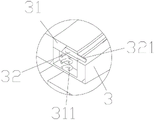
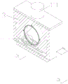
The mounting plate is provided with a second through hole, the inner wall of the second through hole is provided with a mounting ring 31, the mounting ring is made of plastic, the mounting ring is provided with a connecting groove, a fixing ring 32 is arranged in the connecting groove, the fixing ring is also made of plastic, the fixing ring is connected with the connecting groove through tight fit, the fixing ring is provided with a sixth connecting rod 321, and the sixth connecting rod is arranged so that the fixing ring can be taken out of the connecting groove; the filter screen is arranged on the mounting ring; a second sliding block is arranged on the side wall of the mounting plate, and a second sliding groove matched with the second sliding block is arranged on the inner wall of the box body; when the filter screen is installed, the filter screen is laid on the mounting ring, the filter screen is arranged on the periphery of the connecting groove, the fixing ring is plugged into the connecting groove, the filter screen is fixed in the connecting groove, the cover plate is opened, the second sliding block is aligned with the second sliding groove, and the mounting plate is installed in the box body to complete the installation of the filter screen.
The inner wall of the material receiving box is rotatably connected with a transmission plate 23, one end of the transmission plate is arranged below the mounting plate, the transmission plate is provided with a second push block 221, the bottom of the lug is provided with a cambered surface, the bottom of the mounting plate is provided with a through groove matched with the second push block, and the second push block penetrates through the through groove and is contacted with the bottom of the mounting ring; a third movable cavity is arranged on the inner wall of the second through hole, a connecting spring 311 is arranged in the third movable cavity, and one end of the connecting spring is fixedly connected to the fixed ring; a fourth movable groove is arranged on the side wall of the connecting pipe, a second connecting plate 271 matched with the fourth movable groove is arranged on the side wall of the fifth connecting rod, and a third push block 272 is arranged at the bottom of the second connecting plate; when the fifth connecting rod is pulled to move downwards by the connecting rope, the fifth connecting rod drives the second connecting plate to move downwards, the second connecting plate drives the third push block to move downwards, the third push block pushes one end of the transmission plate to move downwards, the transmission plate overturns around the connecting point, the second push block moves upwards to extrude the installation ring, the installation ring is deformed, when the fifth connecting rod moves upwards, the transmission plate is in a horizontal state during overturning, under the elastic action of the connecting spring and the installation ring, the installation ring is reset, the installation ring drives the filter screen to shake when resetting, dust on the filter screen is shaken off, the situation that too much dust is blocked on the filter screen to influence the air circulation is avoided, and the service life of the filter screen is prolonged.