CN110582178B - Inside switch board that has installation component that slides - Google Patents
Inside switch board that has installation component that slides Download PDFInfo
- Publication number
- CN110582178B CN110582178B CN201910851828.0A CN201910851828A CN110582178B CN 110582178 B CN110582178 B CN 110582178B CN 201910851828 A CN201910851828 A CN 201910851828A CN 110582178 B CN110582178 B CN 110582178B
- Authority
- CN
- China
- Prior art keywords
- sliding
- cabinet body
- door
- control cabinet
- installation component
- Prior art date
- Legal status (The legal status is an assumption and is not a legal conclusion. Google has not performed a legal analysis and makes no representation as to the accuracy of the status listed.)
- Active
Links
Images


Classifications
-
- H—ELECTRICITY
- H05—ELECTRIC TECHNIQUES NOT OTHERWISE PROVIDED FOR
- H05K—PRINTED CIRCUITS; CASINGS OR CONSTRUCTIONAL DETAILS OF ELECTRIC APPARATUS; MANUFACTURE OF ASSEMBLAGES OF ELECTRICAL COMPONENTS
- H05K5/00—Casings, cabinets or drawers for electric apparatus
- H05K5/0017—Casings, cabinets or drawers for electric apparatus with operator interface units
-
- H—ELECTRICITY
- H05—ELECTRIC TECHNIQUES NOT OTHERWISE PROVIDED FOR
- H05K—PRINTED CIRCUITS; CASINGS OR CONSTRUCTIONAL DETAILS OF ELECTRIC APPARATUS; MANUFACTURE OF ASSEMBLAGES OF ELECTRICAL COMPONENTS
- H05K5/00—Casings, cabinets or drawers for electric apparatus
- H05K5/02—Details
- H05K5/0217—Mechanical details of casings
-
- H—ELECTRICITY
- H05—ELECTRIC TECHNIQUES NOT OTHERWISE PROVIDED FOR
- H05K—PRINTED CIRCUITS; CASINGS OR CONSTRUCTIONAL DETAILS OF ELECTRIC APPARATUS; MANUFACTURE OF ASSEMBLAGES OF ELECTRICAL COMPONENTS
- H05K7/00—Constructional details common to different types of electric apparatus
- H05K7/14—Mounting supporting structure in casing or on frame or rack
-
- H—ELECTRICITY
- H05—ELECTRIC TECHNIQUES NOT OTHERWISE PROVIDED FOR
- H05K—PRINTED CIRCUITS; CASINGS OR CONSTRUCTIONAL DETAILS OF ELECTRIC APPARATUS; MANUFACTURE OF ASSEMBLAGES OF ELECTRICAL COMPONENTS
- H05K7/00—Constructional details common to different types of electric apparatus
- H05K7/18—Construction of rack or frame
Abstract
The invention relates to the field of control cabinets, in particular to a control cabinet with a sliding installation assembly inside, which comprises a cabinet body, wherein one side of the cabinet body is rotatably connected with a first door through a hinge, a separation plate is fixedly installed inside the cabinet body, one side of the separation plate is rotatably connected with a second door through a hinge, two first guide strips are fixedly installed on one side of the separation plate and one side of the inside of the cabinet body, two second guide strips are fixedly installed on the other side of the separation plate and the other side of the inside of the cabinet body, and a sliding plate is arranged on each second guide strip. The invention has the advantages that the up-and-down movement of the junction box and the sliding plate can be realized, the installation personnel can reasonably utilize the space in the control cabinet, the flexible adjustment of the control cabinet is improved, the junction box and the sliding plate have better stability when in use, the installation of the working personnel and the connection of an external electric wire to the junction box are convenient, and the rationality of the design of the control cabinet is improved.
Description
Technical Field
The invention relates to the field of control cabinets, in particular to a control cabinet with a sliding installation assembly inside.
Background
The control cabinet is formed by assembling switch equipment, measuring instruments, protective electrical appliances and auxiliary equipment in a closed or semi-closed metal cabinet or on a screen according to the electrical wiring requirements, and the arrangement of the control cabinet meets the requirements of normal operation of an electric power system, is convenient to overhaul and does not endanger the safety of people and surrounding equipment. In normal operation, the circuit can be switched on or off by means of a manual or automatic switch. When the fault or abnormal operation occurs, the circuit is cut off or an alarm is given by the aid of the protective electric appliance. The measuring instrument can display various parameters in operation, and can also adjust some electrical parameters to prompt or send out signals for deviation from normal working state. The device is commonly used in various power generation, distribution and transformation substations.
The Chinese application number CN201910052286.0 specifically relates to a PLC control cabinet convenient for wiring, which comprises a cabinet body, a cabinet door and a wiring board, wherein the cabinet door is hinged to one surface of the cabinet body, a supporting plate is fixedly installed inside the cabinet body, the wiring board is installed on the supporting plate through bolts, a plurality of accommodating grooves are formed in the wiring board, wiring posts are arranged inside the accommodating grooves, springs are arranged between the wiring posts and the wiring board, two ends of each spring are respectively and fixedly connected with one end of each wiring post and the inner bottom surface of each accommodating groove, a post cap is fixedly installed at one end, away from the springs, of each wiring post, a wiring board is fixedly installed at the front side of the bottom end of the supporting plate, a plurality of threading holes are formed in the rear surface of; this PLC switch board wiring is convenient, can reduce staff's working strength effectively, practices thrift the wiring time, can arrange the circuit simultaneously, and the wiring is clear, the later stage of being convenient for overhauls.
Present can not realize that junction box and sliding plate reciprocate, be not convenient for the inside space of the reasonable utilization switch board of installer, the nimble adjustment nature of switch board is relatively poor, and junction box and sliding plate do not have better stability when using, on the staff's of not being convenient for installation and the wiring board of external electric wire access, the not high shortcoming of rationality of switch board design. Therefore, it is highly desirable to develop a control cabinet with a sliding installation component inside.
Disclosure of Invention
The invention aims to provide a control cabinet with a sliding installation component inside, and aims to solve the problems that a junction box and a sliding plate cannot move up and down, installation personnel cannot reasonably utilize the space inside the control cabinet, the flexibility and adjustability of the control cabinet are poor, the junction box and the sliding plate do not have good stability when in use, installation of the working personnel and connection of an external electric wire to a wiring board are inconvenient, and the reasonability of the design of the control cabinet is low.
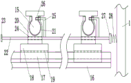
The technical scheme of the invention is as follows: a control cabinet with a sliding installation component inside comprises a cabinet body, wherein one side of the cabinet body is rotatably connected with a first door through a hinge, a separation plate is fixedly installed inside the cabinet body, one side of the separation plate is rotatably connected with a second door through a hinge, two first guide strips are fixedly installed on one side of the separation plate and one side inside the cabinet body, two second guide strips are fixedly installed on the other side of the separation plate and the other side inside the cabinet body, a sliding plate is arranged on each second guide strip, a junction box is arranged on each first guide strip, two sliding strips are arranged on each two sides of the junction box, a connecting block is arranged on one side of each sliding strip, a first sliding groove is formed in one side of the connecting block, a sliding block is fixedly connected to the other side of the connecting block, a second sliding groove is formed in one side of the sliding block, and the second sliding groove is clamped on the first guide strip, the front of sliding block is opened there is the guiding hole, the inside activity grafting of guiding hole has first connecting rod, the one end of first connecting rod is provided with the ejector pad, the other end of first connecting rod is provided with the bearing plate, and one side fixed mounting of bearing plate has first compression spring, and first compression spring's other end swing joint is on the cabinet body, open one side of first gib block has the first spacing groove of equidistance distribution one side of first connecting rod is provided with two first L type gag lever posts, and the one end that first connecting rod was kept away from to first L type gag lever post is pegged graft at first spacing inslot.
Furthermore, the front of the sliding plate is provided with two guide grooves, a second connecting rod is inserted into the guide grooves, one side of the second connecting rod is provided with two second L-shaped limiting rods, a cavity is formed in the sliding plate, the second L-shaped limiting rods slide in the cavity, second compression springs are arranged on the second connecting rod and one side of each second L-shaped limiting rod, one side of each second guide strip is provided with second limiting grooves distributed equidistantly, one end of each second L-shaped limiting rod is inserted into the second limiting groove, and two third sliding grooves are formed in the two sides of the sliding plate.
Furthermore, the junction box is connected to the first guide strip in a sliding mode through a second sliding groove in the sliding block, the junction box is connected to the connecting block in a sliding mode through matching of the sliding strip and the first sliding groove, and the sliding plate is connected to the second guide strip in a sliding mode through a third sliding groove.
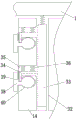
Further, the inside of junction box is provided with a plurality of wiring boards, and the wiring board is the equidistance and distributes, the arc wall that has the equidistance to distribute is all opened to top and bottom in the junction box, the top and the bottom of wiring board all are provided with the arc strip that the equidistance distributes, and arc strip sliding connection is in the arc wall.
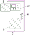
Furthermore, one side of the first box door and one side of the second box door are both provided with an observation window, and handles are fixedly mounted on the one sides of the first box door and the second box door.
Furthermore, a groove is formed in one side of the second box door, a display panel is arranged in the groove, and a display screen, two switches and two indicator lamps are arranged on one side of the display panel.
Furthermore, one side of the second box door is rotatably connected with a glass door through a hinge, and one side of the glass door is provided with a convex block.
Furthermore, one side of the cabinet body is provided with a ventilating grid, and a dustproof net is fixedly arranged inside the ventilating grid.
Further, the top of the cabinet body is provided with a sucker, a warning light is installed at the top of the sucker, and the warning light is installed on the cabinet body through the sucker.
Further, the bottom fixed mounting of the cabinet body has the base, and the bottom of base is provided with the rubber layer.
The invention provides a control cabinet with a sliding installation component inside through improvement, and compared with the prior art, the invention has the following improvements and advantages:
(1) through the gib block, sliding block and the sliding plate that set up, slide from top to bottom on first gib block through the second sliding tray on the sliding block, can realize that the junction box reciprocates, the space in the reasonable utilization wiring storehouse of installer of being convenient for, slide from top to bottom on the second gib block through the third sliding tray on the sliding plate, can realize that the sliding plate reciprocates, the size of installer rational distribution display storehouse of being convenient for and distribution storehouse has improved the nimble regulation nature of switch board.
(2) Through L type gag lever post and the spacing groove that sets up, peg graft at first spacing inslot through first L type gag lever post, can realize sliding block fixed connection on first gib block, peg graft at second spacing inslot through second L type gag lever post, can realize sliding plate fixed connection on the second gib block, prevent sliding plate and junction box lapse, improved the stability of junction box and sliding plate when using the switch board.
(3) Through the sliding strip and the connecting block that set up, the sliding strip slides in the first sliding tray on the connecting block, can realize that the junction box takes out from the storehouse of working a telephone switchboard, and the staff of being convenient for looks over the whole junction box condition of working a telephone switchboard, has improved the work efficiency of staff later stage inspection junction box.
(4) Through the wiring board and the arc wall that set up, the arc strip at both ends slides in the arc wall about the wiring board, can make the wiring board take out in the junction box, and the staff's of being convenient for installation has improved staff's work efficiency with on inserting the wiring board to external electric wire.
(5) Through the glass door that sets up, the glass door sets up on display panel, not only can prevent that non-staff or staff from touching display panel by mistake, can prevent moreover that dust or rainwater from touching display panel, adopts transparent glass door can look over the data of inside display screen under the condition of not opening glass door, has improved the rationality of switch board design.
Drawings
The invention is further explained below with reference to the figures and examples:
FIG. 1 is a schematic view of the overall structure of the present invention;
FIG. 2 is a schematic view of the internal structure of the present invention;
FIG. 3 is a schematic view of a second door of the present invention;
FIG. 4 is a schematic view of the slider structure of the present invention;
FIG. 5 is a schematic plan view of the slider of the present invention;
FIG. 6 is a schematic view of the kinematic structure of the first link of the present invention;
FIG. 7 is a schematic view of the kinematic structure of the second link of the present invention;
FIG. 8 is an enlarged schematic view of the structure of A of the present invention;
FIG. 9 is a schematic view of a first limiting groove structure according to the present invention;
description of reference numerals:
1-cabinet body, 2-first door, 3-second door, 4-observation window, 5-glass door, 6-handle, 7-lug, 8-sucker, 9-warning lamp, 10-ventilating grid, 11-dust screen, 12-base, 13-isolation plate, 14-sliding plate, 15-first guide strip, 16-junction box, 17-sliding strip, 18-connecting block, 19-first sliding groove, 20-sliding block, 21-second sliding groove, 22-first connecting rod, 23-push block, 24-guide hole, 25-first L-shaped limiting rod, 26-first limiting groove, 27-bearing plate, 28-first compression spring, 29-wiring board, 30-arc groove, 31-arc strip, 32-a guide groove, 33-a second connecting rod, 34-a second L-shaped limiting rod, 35-a cavity, 36-a second compression spring, 37-a display panel, 38-a second guide bar, 39-a second limiting groove and 40-a third sliding groove.
Detailed Description
The present invention will be described in detail with reference to fig. 1 to 9, and the technical solutions in the embodiments of the present invention will be clearly and completely described below, and it is obvious that the described embodiments are only a part of the embodiments of the present invention, and not all embodiments. All other embodiments, which can be derived by a person skilled in the art from the embodiments given herein without making any creative effort, shall fall within the protection scope of the present invention.
The invention provides a control cabinet with a sliding installation component inside through improvement, as shown in figures 1-9, the control cabinet comprises a cabinet body 1, one side of the cabinet body 1 is rotatably connected with a first door 2 through a hinge, a separation plate 13 is fixedly installed inside the cabinet body 1, the separation plate 13 separates the space inside the cabinet body 1 to realize the independent operation of the equipment inside the cabinet body 1, one side of the separation plate 13 is rotatably connected with a second door 3 through a hinge, two first guide strips 15 are fixedly installed on one side of the separation plate 13 and one side inside the cabinet body 1, a second sliding groove 21 on a sliding block 20 slides up and down on the first guide strips 15 to realize the up-and-down movement of a junction box 16, so that an installer can reasonably utilize the space inside the junction box, two second guide strips 38 are fixedly installed on the other side of the separation plate 13 and the other side inside the cabinet body 1, a third sliding groove 40 on the sliding plate 14 slides up and down on the second guide strip 38 to realize the up-and-down movement of the sliding plate 14, the sliding plate 14 is arranged on the second guide strip 38, the connection box 16 is arranged on the first guide strip 15 and used for protecting the connection board 29, two sliding strips 17 are arranged on two sides of the connection box 16, the sliding strips 17 slide in first sliding grooves 19 on the connection blocks to realize the extraction of the connection box 16 from the connection cabin, one side of each sliding strip 17 is provided with a connection block 18, one side of each connection block 18 is provided with a first sliding groove 19, the other side of each connection block 18 is fixedly connected with a sliding block 20, one side of each sliding block 20 is provided with a second sliding groove 21, the second sliding groove 21 is clamped on the first guide strip 15 in a sliding manner, the front surface of each sliding block 20 is provided with a guide hole 24, a first connecting rod 22 is movably inserted in the guide hole 24, and the first compression spring 28 is extruded by the extrusion push block 23 through the first connecting rod 22 and the plate 27 to separate the first L- A spacing groove 26, can adjust the position of junction box 16 in the wiring storehouse, the one end of first connecting rod 22 is provided with ejector pad 23, the other end of first connecting rod 22 is provided with bearing plate 27, and one side fixed mounting of bearing plate 27 has first compression spring 28, and the other end swing joint of first compression spring 28 is on the cabinet body 1, one side of opening the first connecting rod 22 that has the first spacing groove 26 that the equidistance distributes in one side of first gib block 15 is provided with two first L type gag lever posts 25, and the one end that first L type gag lever post 25 keeps away from first connecting rod 22 is pegged graft in first spacing groove 26.
Furthermore, the front surface of the sliding plate 14 is provided with two guide grooves 32, a second connecting rod 33 is inserted into the guide grooves 32, one side of the second connecting rod 33 is provided with two second L-shaped limiting rods 34, the interior of the sliding plate 14 is provided with a cavity 35, and the second L-shaped limiting rod 34 slides in the cavity 35, one side of the second connecting rod 33 and one side of the second L-shaped limiting rod 34 are both provided with a second compression spring 36, one end of the second L-shaped limiting rod 34 can smoothly enter the second limiting groove 39, one side of the second guide strip 38 is provided with second limiting grooves 39 distributed at equal intervals, one end of the second L-shaped limiting rod 34 is inserted into the second limiting groove 39, two third sliding grooves 40 are respectively arranged on two sides of the sliding plate 14, the sliding plate 14 can be fixedly connected to the second guide bar 38 by inserting the second L-shaped limiting rod 34 into the second limiting groove 39, so that the sliding plate 14 is prevented from sliding downwards on the second guide bar 38.
Further, the junction box 16 is slidably connected to the first guide bar 15 through the second sliding groove 21 of the sliding block 20, the junction box 16 is slidably connected to the connecting block 18 through the cooperation of the sliding bar 17 and the first sliding groove 19, and the sliding plate 14 is slidably connected to the second guide bar 38 through the third sliding groove 40.
Further, the inside of junction box 16 is provided with a plurality of wiring boards 29, and wiring boards 29 are the equidistance and distribute, arc 30 that the equidistance distributes has all been opened at the top in the junction box 16 and bottom, arc 31 that the equidistance distributes all is provided with at the top and the bottom of wiring board 29, and arc 31 sliding connection is in arc 30, arc 31 through both ends about wiring board 29 slides in arc 30, can make wiring board 29 take out in junction box 16, be convenient for the staff installation and insert on wiring board 29 the external electric wire.
Further, one side of first chamber door 2 and second chamber door 3 all is provided with observation window 4, does not open under the condition of first chamber door 2 and second chamber door 3, can observe the inside condition of switch board, and the equal fixed mounting in one side of first chamber door 2 and second chamber door 3 has handle 6.
Further, one side of the second box door 3 is provided with a groove, a display panel 37 is arranged in the groove and used for controlling and operating a platform for outputting of the control cabinet, and a display screen, two switches and two indicating lamps are arranged on one side of the display panel 37.
Further, one side of second chamber door 3 is connected with glass door 5 through the hinge rotation, and glass door 5 adopts the transparent glass material, not only can prevent that non-staff or staff from touching display panel 37 by mistake, can prevent moreover that dust or rainwater from contacting display panel 37 on, one side of glass door 5 is provided with lug 7, is convenient for open glass door 5.
Furthermore, one side of the cabinet body 1 is provided with a ventilating grid 10, so that heat dissipation and ventilation can be performed on the electrical equipment in the control cabinet, and the dust screen 11 is fixedly mounted inside the ventilating grid 10, so that dust can be prevented from entering the cabinet body 1.
Further, the top of the cabinet body 1 is provided with the sucking disc 8, and the warning light 9 is installed at the top of sucking disc 8, and the warning light 9 lights when the switch board goes wrong, not only is the staff of being convenient for in time discover the switch board that goes wrong, can be quick moreover find the switch board that goes wrong, and the warning light 9 passes through sucking disc 8 to be installed on the cabinet body 1, and the staff of being convenient for removes and fixes warning light 9.
Further, the bottom fixed mounting of the cabinet body 1 has a base 12, the base 12 of the bottom of the cabinet body 1 can make the cabinet body 1 have a certain clearance with the ground, prevent the cabinet body 1 from being corroded by the ground, improve the service life of the cabinet body 1, and the bottom of the base 12 is provided with a rubber layer, so that the cabinet has a better corrosion resistance characteristic.
The working principle is as follows: when the wiring box is used, the control cabinet is placed at a designated position, when wiring is conducted on the control cabinet, the door 2 is opened through the handle 6 on the first door 2, when the height position of the wiring box 16 needs to be adjusted, the pushing blocks 23 on two sides of the wiring box 16 can be pushed, the pushing blocks 23 drive the first connecting rod 22 to slide in the first sliding groove 19, the pressure bearing plate 27 at the other end of the first connecting rod 22 extrudes the first compression spring 28 to deform, meanwhile, one end of the first L-shaped limiting rod 25 on the first connecting rod 22 is pulled out from the first limiting groove 26 on the first guide strip 15, so that the wiring box 16 moves up and down on the first guide strip 15, when the wiring box moves to the designated position, the pushing blocks 23 are loosened, the bearing plate 27 and the first connecting rod 22 are pushed through the self elastic force of the first compression spring 28, so that the first L-shaped limiting rod 25 is pushed to enter the first limiting groove 26 which is closest to the first L-shaped limiting rod 25 below the first guide strip 15, the wiring box 16 is fixed at the required position in the wiring cabin, the space in the wiring cabin can be fully utilized, then the wiring board 29 is taken out, the arc-shaped strips 31 at the upper end and the lower end of the wiring board 29 are drawn out from the arc-shaped grooves 30, wiring is installed on the wiring board 29, then the wiring board 29 is pushed into the wiring box 16, then the first box door 2 is closed, the second box door 3 is opened through the handle 6 with the height of the second box door 3, when the position of the sliding plate 14 needs to be adjusted, the second connecting rod 33 in the guide groove 32 on the sliding plate 14 can be pushed, the second connecting rod 33 drives the second L-shaped limiting rod 34 to move in the cavity 35, the second L-shaped limiting rod 34 is inserted into one end of the second limiting groove 39 on the second guide strip 38, one end of the second L-shaped limiting rod 34 is separated from the second limiting groove 39, and simultaneously the second compression spring 36 at one side of the second L-shaped limiting rod 34 and one end of the second connecting rod 33 is compressed, then the third sliding groove 40 on the sliding plate 14 moves up and down on the second guiding strip 38, when the sliding plate 14 moves to the required position, the second connecting rod 33 is loosened, then one end of the second L-shaped limiting rod 34 enters into the nearest second limiting groove 39 through the self elasticity of the second compression spring 36, so that the sliding plate 14 is fixed at the required position, the sizes of the display cabin and the power distribution cabin can be reasonably and respectively adjusted through adjusting the sliding plate 14, the space is reasonably utilized, then the second door 3 is closed, the control cabinet is started, then the display data of the display screen in the display panel 37 can be observed through the glass door 5, when the adjustment is required, the glass door 5 can be opened, the adjustment is carried out through the display panel 37, and then the warning lamp 9 is adsorbed on the cabinet body 1 through the sucking disc 8, so that the worker can conveniently check the warning lamp.
The previous description of the disclosed embodiments is provided to enable any person skilled in the art to make or use the present invention. Various modifications to these embodiments will be readily apparent to those skilled in the art, and the generic principles defined herein may be applied to other embodiments without departing from the spirit or scope of the invention. Thus, the present invention is not intended to be limited to the embodiments shown herein but is to be accorded the widest scope consistent with the principles and novel features disclosed herein.
Claims (10)
1. The utility model provides an inside switch board that has installation component that slides, includes the cabinet body (1), its characterized in that: one side of the cabinet body (1) is rotatably connected with a first door (2) through a hinge, a separation plate (13) is fixedly installed inside the cabinet body (1), one side of the separation plate (13) is rotatably connected with a second door (3) through a hinge, two first guide strips (15) are fixedly installed on one side of the separation plate (13) and one side inside the cabinet body (1), two second guide strips (38) are fixedly installed on the other side of the separation plate (13) and the other side inside the cabinet body (1), a sliding plate (14) is arranged on each second guide strip (38), a wiring box (16) is arranged on each first guide strip (15), two sliding strips (17) are arranged on each side of the wiring box (16), a connecting block (18) is arranged on one side of each sliding strip (17), and a first sliding groove (19) is formed in one side of each connecting block (18), the other side of the connecting block (18) is fixedly connected with a sliding block (20), one side of the sliding block (20) is provided with a second sliding groove (21), the second sliding groove (21) is connected to the first guide strip (15) in a sliding and clamping manner, the front side of the sliding block (20) is provided with a guide hole (24), a first connecting rod (22) is movably inserted into the guide hole (24), one end of the first connecting rod (22) is provided with a push block (23), the other end of the first connecting rod (22) is provided with a pressure bearing plate (27), one side of the pressure bearing plate (27) is fixedly provided with a first compression spring (28), the other end of the first compression spring (28) is movably connected to the cabinet body (1), one side of the first guide strip (15) is provided with first limiting grooves (26) which are distributed at equal intervals, one side of the first connecting rod (22) is provided with two first L-shaped limiting rods (25), and one end of the first L-shaped limiting rod (25) far away from the first connecting rod (22) is inserted in the first limiting groove (26).
2. The control cabinet with the sliding installation component inside according to claim 1, characterized in that: the front surface of the sliding plate (14) is provided with two guide grooves (32), a second connecting rod (33) is inserted into the guide grooves (32), one side of the second connecting rod (33) is provided with two second L-shaped limiting rods (34), a cavity (35) is formed in the sliding plate (14), the second L-shaped limiting rods (34) slide in the cavity (35), one sides of the second connecting rod (33) and the second L-shaped limiting rods (34) are respectively provided with a second compression spring (36), one side of each second guide strip (38) is provided with second limiting grooves (39) which are distributed equidistantly, one end of each second L-shaped limiting rod (34) is inserted into each second limiting groove (39), and two sides of the sliding plate (14) are respectively provided with two third sliding grooves (40).
3. The control cabinet with the sliding installation component inside according to claim 1, characterized in that: the connection box (16) is connected to the first guide strip (15) in a sliding mode through a second sliding groove (21) in the sliding block (20), the connection box (16) is connected to the connecting block (18) in a sliding mode through the matching of the sliding strip (17) and the first sliding groove (19), and the sliding plate (14) is connected to the second guide strip (38) in a sliding mode through a third sliding groove (40).
4. The control cabinet with the sliding installation component inside according to claim 1, characterized in that: the inside of junction box (16) is provided with a plurality of wiring boards (29), and wiring board (29) are the equidistance and distribute, arc wall (30) that the equidistance distributes have all been opened to top and bottom in junction box (16), the top and the bottom of wiring board (29) all are provided with arc strip (31) that the equidistance distributes, and arc strip (31) sliding connection is in arc wall (30).
5. The control cabinet with the sliding installation component inside according to claim 1, characterized in that: one side of first chamber door (2) and second chamber door (3) all is provided with observation window (4), the equal fixed mounting in one side of first chamber door (2) and second chamber door (3) has handle (6).
6. The control cabinet with the sliding installation component inside according to claim 1, characterized in that: a groove is formed in one side of the second box door (3), a display panel (37) is arranged in the groove, and a display screen, two switches and two indicating lamps are arranged on one side of the display panel (37).
7. The control cabinet with the sliding installation component inside according to claim 1, characterized in that: one side of the second box door (3) is rotatably connected with a glass door (5) through a hinge, and one side of the glass door (5) is provided with a convex block (7).
8. The control cabinet with the sliding installation component inside according to claim 1, characterized in that: one side of the cabinet body (1) is provided with a ventilating grid (10), and a dustproof net (11) is fixedly arranged inside the ventilating grid (10).
9. The control cabinet with the sliding installation component inside according to claim 1, characterized in that: the top of the cabinet body (1) is provided with a sucker (8), a warning lamp (9) is installed at the top of the sucker (8), and the warning lamp (9) is installed on the cabinet body (1) through the sucker (8).
10. The control cabinet with the sliding installation component inside according to claim 1, characterized in that: the bottom of the cabinet body (1) is fixedly provided with a base (12), and a rubber layer is arranged at the bottom of the base (12).
Priority Applications (1)
| Application Number | Priority Date | Filing Date | Title |
|---|---|---|---|
| CN201910851828.0A CN110582178B (en) | 2019-09-10 | 2019-09-10 | Inside switch board that has installation component that slides |
Applications Claiming Priority (1)
| Application Number | Priority Date | Filing Date | Title |
|---|---|---|---|
| CN201910851828.0A CN110582178B (en) | 2019-09-10 | 2019-09-10 | Inside switch board that has installation component that slides |
Publications (2)
| Publication Number | Publication Date |
|---|---|
| CN110582178A CN110582178A (en) | 2019-12-17 |
| CN110582178B true CN110582178B (en) | 2020-11-10 |
Family
ID=68812920
Family Applications (1)
| Application Number | Title | Priority Date | Filing Date |
|---|---|---|---|
| CN201910851828.0A Active CN110582178B (en) | 2019-09-10 | 2019-09-10 | Inside switch board that has installation component that slides |
Country Status (1)
| Country | Link |
|---|---|
| CN (1) | CN110582178B (en) |
Families Citing this family (2)
| Publication number | Priority date | Publication date | Assignee | Title |
|---|---|---|---|---|
| CN113745998B (en) * | 2021-08-26 | 2023-10-27 | 安庆船用电器有限责任公司 | Marine gas engine control cabinet |
| CN117477388A (en) * | 2023-10-30 | 2024-01-30 | 广东科源电气股份有限公司 | Compact box-type transformer substation |
Family Cites Families (8)
| Publication number | Priority date | Publication date | Assignee | Title |
|---|---|---|---|---|
| CN203040036U (en) * | 2012-11-30 | 2013-07-03 | 海宁中韩科技发展有限公司 | Screen cabinet |
| CN204168644U (en) * | 2014-09-30 | 2015-02-18 | 四川蓝讯宝迩电子科技有限公司 | Free distribution type circuit boards case |
| CN206272996U (en) * | 2016-12-23 | 2017-06-20 | 海安汇珏网络通信设备有限公司 | A kind of pair of storehouse outdoor cabinet |
| CN208387103U (en) * | 2018-07-02 | 2019-01-15 | 河源华盈科技有限公司 | A kind of automation equipment control cabinet |
| CN208537396U (en) * | 2018-07-17 | 2019-02-22 | 南京客莱沃智能科技有限公司 | A kind of photocaustic spectroscopy transformer online monitoring protection cabinets |
| CN208956385U (en) * | 2018-08-22 | 2019-06-07 | 昆山竞能电气有限公司 | A kind of heat sinking PLC control cabinet |
| CN109548347B (en) * | 2018-11-12 | 2020-06-30 | 内蒙古华讯软件有限公司 | Internet big data server cabinet capable of realizing intelligentization of maintenance process |
| CN110113908B (en) * | 2019-05-17 | 2020-12-08 | 龙岩逸狼网络科技有限公司 | Cloud data storage device |
-
2019
- 2019-09-10 CN CN201910851828.0A patent/CN110582178B/en active Active
Also Published As
| Publication number | Publication date |
|---|---|
| CN110582178A (en) | 2019-12-17 |
Similar Documents
| Publication | Publication Date | Title |
|---|---|---|
| CN110582178B (en) | Inside switch board that has installation component that slides | |
| CN110048310B (en) | High-voltage direct-current intelligent power distribution unit | |
| CN109921306A (en) | A kind of switchgear of easy access | |
| CN113471844A (en) | Safe and reliable high-low voltage switch cabinet | |
| CN202026023U (en) | Drawer type combined switch cabinet | |
| CN216564104U (en) | Control cabinet for light current intelligent engineering | |
| CN211859255U (en) | Double-guide-rod electrical control cabinet | |
| CN212412508U (en) | Electric lighting power distribution cabinet | |
| CN209344582U (en) | A kind of protective device of high-low pressure electronic box | |
| CN219513649U (en) | Switch cabinet | |
| CN219760369U (en) | Auxiliary lighting device for maintenance of distribution box | |
| CN219513568U (en) | Automatic illumination electric control cabinet | |
| CN220732155U (en) | Switch cabinet convenient to overhaul | |
| CN214625779U (en) | Power control cabinet with dampproofing dustproof function | |
| CN220138954U (en) | Connecting piece for electrical switch cabinet | |
| CN116960777B (en) | Electric control cabinet | |
| CN217469121U (en) | Distribution box convenient for wire arrangement | |
| CN214798359U (en) | Electric control cabinet convenient for installation of electrical equipment | |
| CN215735179U (en) | Power connection control cabinet convenient to overhaul | |
| CN213602204U (en) | Safety protection device for electric control cabinet | |
| CN212085510U (en) | Embedded installation type mobile power distribution cabinet | |
| CN204927931U (en) | Novel cubical switchboard | |
| CN220042581U (en) | Electrical low-voltage complete switch equipment | |
| CN215528305U (en) | Novel draw-out type switch cabinet | |
| CN219627150U (en) | Dual-power multi-standby modularized plug-in type switch cabinet |
Legal Events
| Date | Code | Title | Description |
|---|---|---|---|
| PB01 | Publication | ||
| PB01 | Publication | ||
| SE01 | Entry into force of request for substantive examination | ||
| SE01 | Entry into force of request for substantive examination | ||
| GR01 | Patent grant | ||
| GR01 | Patent grant |