Screw nail gun for assembly
Technical Field
The invention relates to a screw nail gun, in particular to a screw nail gun for assembly.
Background
The screw is often in machinery, electrical apparatus and building etc. and the screw does not need the nut, can directly cooperate with two objects, and the head is generally criticized with the instrument, and the head is mostly a word groove, cross recess, and inside and outside hexagonal is also many, and is generally less.
When two objects are fixed by using the screws at present, an operator needs to hold the screws by one hand, and fix the screws at positions needing to be matched by the other hand by using a corresponding screwdriver, so that the operator needs to align the screwdriver and the screws by hand-eye matching, and the other way is that the operator firstly places the screws at the positions needing to be fixed and then fixes the screws at the positions needing to be matched by using an electric drill with a screwdriver bit, the operation processes of the two ways are too complex, and the operator cannot carry a large number of screws with him.
Therefore, it is desirable to provide an assembly screw gun capable of aligning the driver head and the screws easily and quickly, accommodating a large number of screws, and having a high safety factor, so as to solve the above problems.
Disclosure of Invention
In order to overcome the defect that an operator needs to align a screwdriver and a screw through hand-eye matching and cannot carry a large number of screws, the technical problem to be solved is as follows: the screw nail gun for assembling is capable of aligning a screwdriver head and a screw simply and quickly, accommodating a large number of screws, and being convenient to use and high in safety factor.
The technical scheme of the invention is as follows: the utility model provides a screw nail rifle for assembly, is including having hollow handle and gear motor, and gear motor is installed in hollow handle bottom left side, still including sliding part, bearing frame, criticizing head, drive arrangement and arc, the gear motor bottom is equipped with sliding part, and the bearing frame is installed on sliding part upper portion, and the sliding part bottom is installed and is criticized the head, wherein sliding part is used for driving and criticizes the head and remove, and hollow handle below is equipped with drive arrangement, and drive arrangement's connecting piece is connected with the bearing frame, wherein drive arrangement is used for driving sliding part and criticizes first lapse, and hollow handle right side is articulated to be connected with the arc, arc and hollow handle cooperation.
Furthermore, the sliding part comprises a hexagonal rod, a hexagonal hole sleeve and a first spring, the hexagonal rod is installed on an output shaft of the speed reduction motor, the hexagonal rod is slidably provided with the hexagonal hole sleeve, the bearing seat is installed on the upper portion of the hexagonal hole sleeve, the first spring is connected between the bottom end of the hexagonal rod and the inner bottom of the hexagonal hole sleeve, and the bottom of the hexagonal hole sleeve is connected with the top end of the screwdriver head.
Further, the driving device comprises a handle, a liquid storage frame, a connecting rod, a first piston, a second spring, a liquid outlet pipe, a cylinder body, a second piston and an L-shaped rod, the handle is hinged below the hollow handle, the liquid storage frame is installed on the right side of the bottom of the hollow handle, the connecting rod is installed on the right side of the top of the handle, the upper portion of the connecting rod is located in the liquid storage frame, the first piston is arranged in the liquid storage frame in a sliding mode, the top end of the connecting rod is connected with the bottom of the first piston, the second spring is connected between the right side of the top of the handle and the bottom of the liquid storage frame, the liquid outlet pipe is installed on the left wall of the liquid storage frame and communicated with the liquid storage frame, the liquid outlet pipe is located on the rear side of the hollow handle, the cylinder body is installed on the left side of the hollow handle, the tail end of the liquid outlet, the bottom of the L-shaped rod is connected with the left side of the bearing seat.
Further, the cylinder body comprises a pushing device, the pushing device comprises a connecting rod, a conical cover, a sliding block, a cylinder, a hollow pipe, a baffle, a gear, a rack, a circular ring, a rotating plate, a sliding rod, a contact block, an arc-shaped block and a third spring, the connecting rod is installed on the left side of the cylinder body, the conical cover is installed on the right side of the bottom of the connecting rod, an annular sliding groove is formed in the bottom of the conical cover, the sliding block is arranged in the annular sliding groove in a sliding mode, the cylinder is installed on the top of the sliding block, fifteen placing blind holes are formed in the top of the cylinder, a first through hole is formed in the middle of the top of the cylinder, the hollow pipe is installed in the middle of the conical cover in an embedded mode, the upper portion of the hollow pipe is located in the first through hole, fifteen second through holes are formed in the lower portion of the cylinder, rack and gear engagement, drum outside slidingtype is equipped with the ring, the ring inboard is connected with the rack outside, the articulated rotor plate that is connected with in ring right side, open on hollow tube left side upper portion has the third through-hole, it has the third through-hole also to open in the drum, open the drum lower part has fifteen special-shaped grooves, special-shaped groove communicates with each other in with placing the blind hole, special-shaped inslot slidingtype is equipped with the slide bar, the contact block is installed to the slide bar inboard, the arc piece is installed to connecting rod right side lower part, the arc piece is located the bell top, arc piece and slide bar contact cooperation, be connected with the third spring between contact block outside.
Furthermore, the swing mechanism further comprises a swing plate and a fourth spring, first grooves are uniformly formed in the inner wall of the lower portion of the hollow pipe at intervals, the swing plate is installed in the first grooves in a rotating mode, and the fourth spring is connected between the outer side of the swing plate and the inner wall of the first grooves.
Further, the clamping device comprises a clamping block and a fifth spring, a second groove is formed in the lower portion of the right side of the connecting rod, the clamping block is arranged in the second groove in a sliding mode, the fifth spring is connected between the left end of the clamping block and the inner wall of the second groove, fifteen clamping grooves are formed in the upper portion of the cylinder and correspond to the fifteen placing blind holes, and the clamping grooves are matched with the clamping block.
The beneficial effects are that: according to the invention, hydraulic oil in the liquid storage frame flows into the cylinder body by pressing the handle, so that the L-shaped rod moves downwards to drive the hexagonal hole sleeve to move downwards, a screw placed in the blind hole can fall into the hollow pipe through the contact and matching of the contact block and the sliding rod, and meanwhile, when the screw is in the hollow pipe, the screw can be prevented from falling off by the swinging plate, and an operator can know that the screw falls into the hollow pipe through the matching of the clamping block and the clamping groove.
Drawings
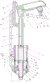
Fig. 1 is a schematic front view of the present invention.
FIG. 2 is a schematic top view of the cylinder of the present invention.
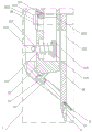
FIG. 3 is an enlarged view of part A of the present invention.
In the reference symbols: 1 hollow handle, 2 speed reducing motor, 3 hexagonal rod, 4 hexagonal hole sleeve, 5 bearing seat, 6 first spring, 7 batch heads, 8 driving device, 81 handle, 82 liquid storage frame, 83 connecting rod, 84 first piston, 85 second spring, 86 liquid outlet pipe, 87 cylinder body, 88 second piston, 89L-shaped rod, 9 arc plate, 10 pushing device, 101 connecting rod, 102 conical cover, 103 annular chute, 104 sliding block, 105 cylinder, 106 placing blind hole, 107 first through hole, 108 hollow pipe, 109 second through hole, 1010 baffle, 1011 gear, 1012 rack, 1013 ring, 1014 rotating plate, 1015 third through hole, 1016 profiled groove, 1017 sliding rod, 1018 contact block, 1019 arc block, 1020 third spring, 11 first groove, 12 swinging plate, 13 fourth spring, 14 second groove, 15 clamping block, 16 clamping groove, 17 fifth spring.
Detailed Description
Embodiments of the present invention will be described in detail below with reference to the accompanying drawings.
Example 1
The utility model provides a screw nail rifle for assembly, as shown in figure 1, including hollow handle 1, gear motor 2, hexagonal pole 3, hexagonal hole cover 4, bearing frame 5, first spring 6, criticize first 7, drive arrangement 8 and arc 9, gear motor 2 is installed in hollow handle 1 bottom left side, install hexagonal pole 3 on gear motor 2's the output shaft, the gliding style is equipped with hexagonal hole cover 4 on hexagonal pole 3, bearing frame 5 is installed on 4 upper portions of hexagonal hole cover, be connected with first spring 6 between the bottom in 3 bottoms of hexagonal pole and the hexagonal hole cover 4, criticize first 7 is installed to the outer bottom of hexagonal hole cover 4, hollow handle 1 below is equipped with drive arrangement 8, wherein drive arrangement 8 is used for driving hexagonal hole cover 4 and slides down, hollow handle 1 right side is articulated to be connected with arc 9, arc 9 and hollow handle 1 cooperation.
The driving device 8 comprises a handle 81, a liquid storage frame 82, a connecting rod 83, a first piston 84, a second spring 85, a liquid outlet pipe 86, a cylinder 87, a second piston 88 and an L-shaped rod 89, wherein the handle 81 is hinged and connected to the lower portion of the hollow handle 1, the liquid storage frame 82 is installed on the right side of the bottom of the hollow handle 1, the connecting rod 83 is installed on the right side of the top of the handle 81, the upper portion of the connecting rod 83 is located in the liquid storage frame 82, the first piston 84 is slidably arranged in the liquid storage frame 82, the top end of the connecting rod 83 is connected with the bottom of the first piston 84, the second spring 85 is connected between the right side of the top of the handle 81 and the bottom of the liquid storage frame 82, the liquid outlet pipe 86 is installed on the left wall of the liquid storage frame 82, the liquid outlet pipe 86 is communicated with the liquid storage frame 82, the liquid outlet pipe 86 is located on the rear, a second piston 88 is arranged in the cylinder 87 in a sliding mode, an L-shaped rod 89 is installed at the bottom of the second piston 88, the L-shaped rod 89 penetrates through the bottom of the cylinder 87, and the bottom of the L-shaped rod 89 is connected with the left side of the bearing block 5.
When an operator fixes two workpieces by using screws, firstly, the operator holds the hollow handle 1, opens the arc-shaped plate 9 to take out the screws in the hollow handle 1, after the screws are taken out, the operator closes the arc-shaped plate 9, places the screws at the positions to be fixed by using the other hand, then enables the screwdriver heads 7 to be matched with the grooves at the tops of the screws, then starts the speed reduction motor 2, the speed reduction motor 2 rotates to drive the hexagonal rod 3 to rotate, the hexagonal rod 3 rotates to drive the hexagonal hole sleeve 4 to rotate, so that the inner screws rotate, the operator presses the handle 81 inwards, the right part of the handle 81 swings upwards, the second spring 85 is compressed therewith, the connecting rod 83 drives the first piston 84 to move upwards in the liquid storage frame 82, so that hydraulic oil in the liquid storage frame 82 flows into the cylinder body 87 through the liquid outlet pipe 86, so that the second piston 88 moves downwards, the second piston 88 moves downwards to drive the L-shaped rod 89 to move downwards, the L-shaped rod 89 moves downwards to drive the hexagonal hole sleeve 4 to move downwards through the bearing seat 5, the first spring 6 is stretched, so that the screw can be drilled into a position to be fixed, after the screw is fixed, an operator turns off the speed reducing motor 2, releases the handle 81, the right part of the handle 81 swings downwards under the action of the second spring 85, the handle 81 swings to drive the connecting rod 83 to move downwards, the connecting rod 83 moves downwards to drive the first piston 84 to move downwards in the liquid storage frame 82, so that hydraulic oil in the cylinder body 87 is pumped into the liquid storage frame 82 through the liquid outlet pipe 86, in the process that the hydraulic oil in the cylinder body 87 flows into the liquid storage frame 82, the hexagonal hole sleeve 4 moves upwards under the action of the reset of the first spring 6, so that the L-shaped rod 89 drives the second piston 88 to move upwards and reset in the cylinder body 87, the hexagonal hole sleeve 4 can be reset, and the operator can use the equipment to drive the screw to drill into a workpiece by repeating the above actions, and fixing the workpiece.
Example 2
On the basis of embodiment 1, as shown in fig. 1-3, the pushing device 10 is further included, the pushing device 10 includes a connecting rod 101, a conical cover 102, a sliding block 104, a cylinder 105, a hollow tube 108, a baffle 1010, a gear 1011, a rack 1012, a circular ring 1013, a rotating plate 1014, a sliding rod 1017, a contact block 1018, an arc block 1019 and a third spring 1020, the connecting rod 101 is installed on the left side of the cylinder 87, the conical cover 102 is installed on the right side of the bottom of the connecting rod 101, an annular sliding slot 103 is formed at the bottom in the conical cover 102, the sliding block 104 is slidably arranged in the annular sliding slot 103, the cylinder 105 is installed on the top of the sliding block 104, fifteen placing blind holes 106 are formed on the top of the cylinder 105, a first through hole 107 is formed in the middle of the top of the cylinder 105, the hollow tube 108 is installed in the middle of the conical cover 102, the upper portion of the hollow tube 108 is located in the, a baffle 1010 is hinged in the second through hole 109, a gear 1011 is arranged at the hinged position of the baffle 1010 and the second through hole 109, the gear 1011 is connected with the baffle 1010, a rack 1012 is arranged in the second through hole 109 in a sliding manner, the rack 1012 is meshed with the gear 1011, a ring 1013 is arranged on the outer side of the cylinder 105 in a sliding manner, the inner side of the ring 1013 is connected with the outer side of the rack 1012, a rotating plate 1014 is hinged on the right side of the ring 1013, a third through hole 1015 is formed in the upper left side of the hollow pipe 108, a third through hole 1015 is also formed in the cylinder 105, fifteen special-shaped grooves 1016 are formed in the lower part of the cylinder 105, the special-shaped grooves 1016 are communicated with the placing blind hole 106, a sliding rod 1017 is arranged in the special-shaped grooves 1016 in a sliding manner, a contact block 1018 is arranged on the inner side of the sliding rod 1017, an arc block 1019 is arranged on the lower part of the right side of the connecting.
After an operator puts screws into the upper part of the placing blind hole 106 on the cylinder 105, the rotating plate 1014 is pulled to drive the ring 1013 to move upwards, the ring 1013 moves upwards to drive the rack 1012 to move upwards, the rack 1012 moves upwards to drive the gear 1011 to rotate clockwise, the gear 1011 rotates clockwise to drive the baffle 1010 to rotate clockwise, so that the baffle 1010 does not block the middle part of the placing blind hole 106, the screws at the upper part of the placing blind hole 106 fall into the lower part of the placing blind hole 106, only one screw is arranged at the lower part of each placing blind hole 106, the ring 1013 is pressed downwards, the ring 1013 moves downwards to drive the rack 1012 to move downwards, the rack 1012 moves downwards to drive the gear 1011 to rotate anticlockwise, the gear 1011 rotates anticlockwise to drive the baffle 1010 to rotate anticlockwise to block the placing blind hole 106, then the cylinder 105 rotates clockwise, and the slider 104 rotates clockwise in the annular chute 103, therefore, the sliding rod 1017 is in contact with the arc-shaped block 1019, when an operator rotates the cylinder 105 clockwise to the third through hole 1015, the sliding rod 1017 moves inwards in the special-shaped groove 1016, the third spring 1020 is stretched, the contact block 1018 pushes a screw into the hollow tube 108 through the third through hole 1015, then the screw is drilled into a position to be fixed through the driving device 8, when the operator fixes a next position after fixing the position, the operator rotates the cylinder 105 clockwise, the previous sliding rod 1017 is separated from the contact block 1018, the previous sliding rod 1017 is reset under the action of the third spring 1020, and the next sliding rod 1017 is matched with the contact block 1018, so that the operator does not need to stabilize the screw by hand, and the danger is reduced.
Example 3
On the basis of the embodiments 1 and 2, as shown in fig. 1 to 3, the vibration plate device further comprises a vibration plate 12 and a fourth spring 13, first grooves 11 are uniformly spaced on the inner wall of the lower part of the hollow tube 108, the vibration plate 12 is rotatably installed in the first grooves 11, and the fourth spring 13 is connected between the outer side of the vibration plate 12 and the inner wall of the first grooves 11.
The cylinder 105 is provided with fifteen clamping grooves 16, the fifteen clamping grooves 16 correspond to the fifteen placing blind holes 106, and the clamping grooves 16 are matched with the clamping blocks 15.
When the screw falls into the hollow tube 108, the swing plate 12 can prevent the screw from directly falling, when the screwdriver bit 7 drives the screw to move downwards, the swing plate 12 swings downwards, the fourth spring 13 is compressed, and when the screwdriver bit 7 is not in contact with the swing plate 12 any more, the swing plate 12 is reset under the action of the fourth spring 13.
When the operator is continuous to rotate drum 105 clockwise, when fixture block 15 and draw-in groove 16 do not cooperate, fixture block 15 just can move left, fifth spring 17 compresses thereupon, continue clockwise rotation as drum 105, right-hand time when draw-in groove 16 is located fixture block 15, under fifth spring 17's effect, alright make fixture block 15 card go into in the draw-in groove 16, two third through holes 1015 just in time correspond this moment, also can make the operator know the screw and push to the hollow tube 108 in simultaneously, the operator is continuous to rotate drum 105 and can know whether the screw is pushed to the hollow tube 108 in.
It should be understood that this example is only for illustrating the present invention and is not intended to limit the scope of the present invention. Further, it should be understood that various changes or modifications of the present invention may be made by those skilled in the art after reading the teaching of the present invention, and such equivalents may fall within the scope of the present invention as defined in the appended claims.