CN110518309B - Multi-cooling-mode power battery heat dissipation device - Google Patents
Multi-cooling-mode power battery heat dissipation device Download PDFInfo
- Publication number
- CN110518309B CN110518309B CN201910826630.7A CN201910826630A CN110518309B CN 110518309 B CN110518309 B CN 110518309B CN 201910826630 A CN201910826630 A CN 201910826630A CN 110518309 B CN110518309 B CN 110518309B
- Authority
- CN
- China
- Prior art keywords
- heat
- heat dissipation
- battery
- box
- power battery
- Prior art date
- Legal status (The legal status is an assumption and is not a legal conclusion. Google has not performed a legal analysis and makes no representation as to the accuracy of the status listed.)
- Expired - Fee Related
Links
- 230000017525 heat dissipation Effects 0.000 title claims abstract description 142
- 238000001816 cooling Methods 0.000 claims abstract description 116
- 238000003860 storage Methods 0.000 claims abstract description 71
- 238000004519 manufacturing process Methods 0.000 claims abstract description 11
- 238000007789 sealing Methods 0.000 claims abstract description 6
- RYGMFSIKBFXOCR-UHFFFAOYSA-N Copper Chemical compound [Cu] RYGMFSIKBFXOCR-UHFFFAOYSA-N 0.000 abstract description 51
- 229910052802 copper Inorganic materials 0.000 abstract description 51
- 239000010949 copper Substances 0.000 abstract description 51
- 238000012546 transfer Methods 0.000 abstract description 15
- 239000000112 cooling gas Substances 0.000 abstract description 9
- 238000009826 distribution Methods 0.000 abstract description 3
- 239000012782 phase change material Substances 0.000 description 24
- 239000002131 composite material Substances 0.000 description 16
- 238000010438 heat treatment Methods 0.000 description 14
- 230000005855 radiation Effects 0.000 description 14
- 239000003292 glue Substances 0.000 description 12
- 238000000034 method Methods 0.000 description 12
- 239000007789 gas Substances 0.000 description 11
- 230000000149 penetrating effect Effects 0.000 description 9
- 229910052782 aluminium Inorganic materials 0.000 description 8
- XAGFODPZIPBFFR-UHFFFAOYSA-N aluminium Chemical compound [Al] XAGFODPZIPBFFR-UHFFFAOYSA-N 0.000 description 8
- 230000000694 effects Effects 0.000 description 8
- 238000005485 electric heating Methods 0.000 description 6
- 229920000642 polymer Polymers 0.000 description 6
- 230000008569 process Effects 0.000 description 5
- 229910000838 Al alloy Inorganic materials 0.000 description 4
- 239000012809 cooling fluid Substances 0.000 description 4
- 239000000110 cooling liquid Substances 0.000 description 4
- 230000008878 coupling Effects 0.000 description 4
- 238000010168 coupling process Methods 0.000 description 4
- 238000005859 coupling reaction Methods 0.000 description 4
- 238000010586 diagram Methods 0.000 description 4
- 238000003780 insertion Methods 0.000 description 4
- 230000037431 insertion Effects 0.000 description 4
- 239000000178 monomer Substances 0.000 description 4
- OKTJSMMVPCPJKN-UHFFFAOYSA-N Carbon Chemical compound [C] OKTJSMMVPCPJKN-UHFFFAOYSA-N 0.000 description 3
- 230000008859 change Effects 0.000 description 3
- 238000005265 energy consumption Methods 0.000 description 3
- 230000002708 enhancing effect Effects 0.000 description 3
- 239000010439 graphite Substances 0.000 description 3
- 229910002804 graphite Inorganic materials 0.000 description 3
- 229910052751 metal Inorganic materials 0.000 description 3
- 239000002184 metal Substances 0.000 description 3
- 238000012986 modification Methods 0.000 description 3
- 230000004048 modification Effects 0.000 description 3
- 238000012544 monitoring process Methods 0.000 description 3
- 238000005192 partition Methods 0.000 description 3
- HBBGRARXTFLTSG-UHFFFAOYSA-N Lithium ion Chemical compound [Li+] HBBGRARXTFLTSG-UHFFFAOYSA-N 0.000 description 2
- 230000009471 action Effects 0.000 description 2
- 238000005260 corrosion Methods 0.000 description 2
- 230000007797 corrosion Effects 0.000 description 2
- 239000000428 dust Substances 0.000 description 2
- 230000005611 electricity Effects 0.000 description 2
- 238000004880 explosion Methods 0.000 description 2
- 239000000835 fiber Substances 0.000 description 2
- 239000012634 fragment Substances 0.000 description 2
- 238000009434 installation Methods 0.000 description 2
- 239000007788 liquid Substances 0.000 description 2
- 229910001416 lithium ion Inorganic materials 0.000 description 2
- GELKBWJHTRAYNV-UHFFFAOYSA-K lithium iron phosphate Chemical compound [Li+].[Fe+2].[O-]P([O-])([O-])=O GELKBWJHTRAYNV-UHFFFAOYSA-K 0.000 description 2
- 239000012188 paraffin wax Substances 0.000 description 2
- 238000012545 processing Methods 0.000 description 2
- 239000004698 Polyethylene Substances 0.000 description 1
- 238000009825 accumulation Methods 0.000 description 1
- 239000000853 adhesive Substances 0.000 description 1
- 230000001070 adhesive effect Effects 0.000 description 1
- 230000009286 beneficial effect Effects 0.000 description 1
- 230000006835 compression Effects 0.000 description 1
- 238000007906 compression Methods 0.000 description 1
- 238000009833 condensation Methods 0.000 description 1
- 230000005494 condensation Effects 0.000 description 1
- 238000013461 design Methods 0.000 description 1
- 238000011161 development Methods 0.000 description 1
- 238000005516 engineering process Methods 0.000 description 1
- 238000001704 evaporation Methods 0.000 description 1
- 230000008020 evaporation Effects 0.000 description 1
- 230000006872 improvement Effects 0.000 description 1
- 229920000573 polyethylene Polymers 0.000 description 1
- 238000002360 preparation method Methods 0.000 description 1
- 238000003825 pressing Methods 0.000 description 1
- 238000011160 research Methods 0.000 description 1
- 230000004044 response Effects 0.000 description 1
- 238000012552 review Methods 0.000 description 1
- 239000000523 sample Substances 0.000 description 1
- 238000005728 strengthening Methods 0.000 description 1
- XLYOFNOQVPJJNP-UHFFFAOYSA-N water Substances O XLYOFNOQVPJJNP-UHFFFAOYSA-N 0.000 description 1
- 238000003466 welding Methods 0.000 description 1
Images


Classifications
-
- H—ELECTRICITY
- H01—ELECTRIC ELEMENTS
- H01M—PROCESSES OR MEANS, e.g. BATTERIES, FOR THE DIRECT CONVERSION OF CHEMICAL ENERGY INTO ELECTRICAL ENERGY
- H01M10/00—Secondary cells; Manufacture thereof
- H01M10/60—Heating or cooling; Temperature control
- H01M10/61—Types of temperature control
- H01M10/613—Cooling or keeping cold
-
- H—ELECTRICITY
- H01—ELECTRIC ELEMENTS
- H01M—PROCESSES OR MEANS, e.g. BATTERIES, FOR THE DIRECT CONVERSION OF CHEMICAL ENERGY INTO ELECTRICAL ENERGY
- H01M10/00—Secondary cells; Manufacture thereof
- H01M10/60—Heating or cooling; Temperature control
- H01M10/62—Heating or cooling; Temperature control specially adapted for specific applications
- H01M10/625—Vehicles
-
- H—ELECTRICITY
- H01—ELECTRIC ELEMENTS
- H01M—PROCESSES OR MEANS, e.g. BATTERIES, FOR THE DIRECT CONVERSION OF CHEMICAL ENERGY INTO ELECTRICAL ENERGY
- H01M10/00—Secondary cells; Manufacture thereof
- H01M10/60—Heating or cooling; Temperature control
- H01M10/65—Means for temperature control structurally associated with the cells
- H01M10/655—Solid structures for heat exchange or heat conduction
- H01M10/6552—Closed pipes transferring heat by thermal conductivity or phase transition, e.g. heat pipes
-
- H—ELECTRICITY
- H01—ELECTRIC ELEMENTS
- H01M—PROCESSES OR MEANS, e.g. BATTERIES, FOR THE DIRECT CONVERSION OF CHEMICAL ENERGY INTO ELECTRICAL ENERGY
- H01M10/00—Secondary cells; Manufacture thereof
- H01M10/60—Heating or cooling; Temperature control
- H01M10/65—Means for temperature control structurally associated with the cells
- H01M10/655—Solid structures for heat exchange or heat conduction
- H01M10/6554—Rods or plates
-
- H—ELECTRICITY
- H01—ELECTRIC ELEMENTS
- H01M—PROCESSES OR MEANS, e.g. BATTERIES, FOR THE DIRECT CONVERSION OF CHEMICAL ENERGY INTO ELECTRICAL ENERGY
- H01M10/00—Secondary cells; Manufacture thereof
- H01M10/60—Heating or cooling; Temperature control
- H01M10/65—Means for temperature control structurally associated with the cells
- H01M10/656—Means for temperature control structurally associated with the cells characterised by the type of heat-exchange fluid
- H01M10/6561—Gases
- H01M10/6563—Gases with forced flow, e.g. by blowers
-
- Y—GENERAL TAGGING OF NEW TECHNOLOGICAL DEVELOPMENTS; GENERAL TAGGING OF CROSS-SECTIONAL TECHNOLOGIES SPANNING OVER SEVERAL SECTIONS OF THE IPC; TECHNICAL SUBJECTS COVERED BY FORMER USPC CROSS-REFERENCE ART COLLECTIONS [XRACs] AND DIGESTS
- Y02—TECHNOLOGIES OR APPLICATIONS FOR MITIGATION OR ADAPTATION AGAINST CLIMATE CHANGE
- Y02E—REDUCTION OF GREENHOUSE GAS [GHG] EMISSIONS, RELATED TO ENERGY GENERATION, TRANSMISSION OR DISTRIBUTION
- Y02E60/00—Enabling technologies; Technologies with a potential or indirect contribution to GHG emissions mitigation
- Y02E60/10—Energy storage using batteries
Landscapes
- Engineering & Computer Science (AREA)
- Manufacturing & Machinery (AREA)
- Chemical & Material Sciences (AREA)
- Chemical Kinetics & Catalysis (AREA)
- Electrochemistry (AREA)
- General Chemical & Material Sciences (AREA)
- Secondary Cells (AREA)
- Battery Mounting, Suspending (AREA)
Abstract
The invention provides a multi-cooling mode power battery heat dissipation device which comprises a heat dissipation box, a box cover used for sealing the heat dissipation box, a plurality of battery storage grooves arranged in the heat dissipation box, an air cooling module and a heat pipe cooling module. Compared with the prior art, the invention has simple and reasonable structure, and carries out surface micro-manufacturing on the air cooling runner, so that the air cooling gas is converted into a turbulent flow state from a laminar flow state, the air cooling gas absorbs the heat of the battery work, and the heat of the battery is further transferred to the outside of the battery. The copper plate is utilized to increase the contact area between the heat pipe and the battery tab and the lower bottom of the battery, improve the heat transfer efficiency of the heat dissipation system, enable the temperature distribution of the battery to be more uniform, reduce the number of the heat pipes and reduce the cost.
Description
Technical Field
The invention relates to the field of heat dissipation of power batteries of electric automobiles and hybrid automobiles, in particular to a heat dissipation device of a power battery with multiple cooling modes.
Background
Nowadays, electric vehicles and hybrid vehicles are receiving great social attention, but there are still obstacles such as battery explosion and the like to hinder the development of electric vehicles, wherein the safety problem of power batteries is more of a cause of the society's improvement of electric vehicles. The explosion of the power battery caused by high working temperature needs to design a set of perfect power battery heat dissipation system to keep the working temperature of the battery pack within a certain range and improve the heat dissipation performance of the power battery. The invention provides a power battery heat dissipation system based on multiple cooling modes of air cooling, fans and heat pipes.A rectangular groove is arranged on an air cooling channel in a surface micro-manufacturing process, so that air cooling fluid is converted into turbulent flow from laminar flow, energy is consumed based on the turbulent flow formed by gas, the gas needs to extract heat generated by a power battery to form turbulent flow, and then the turbulent flow flows to the outside of the power battery, and the heat dissipation effect of the air cooling on the power battery is further enhanced. Secondly, the heat pipes are distributed above the lugs of the power battery and at the bottom of the battery, so that heat accumulated on the lugs when the power battery starts to work and heat accumulated on the bottom of the battery after long-time work are transferred to the outside.
Through mass search, a heat dissipation device in the prior art, such as a power battery module unit and a power battery module disclosed in the publication number CN104253289B, is found. The temperature of each power battery in the power battery module can be uniform, and the stable performance of the power batteries can be ensured. The four sides of conducting strip all are equipped with the frame, and the last plane processing of conducting strip has a plurality of circular blind holes, and the lateral wall of circular blind hole is fixed with the radial protruding shell fragment of metal, and the bottom in the circular blind hole is fixed with the protruding shell fragment of metal axial, is fixed with a plurality of bellied metal connection pieces on four frames of conducting strip, and the below of conducting strip is provided with a plurality of power battery, the lower plane and the anodal welding of a plurality of power battery of the conducting strip that a plurality of circular blind holes correspond. The invention has the advantages of simple structure, uniform heat dissipation, stable performance and low cost, and is used for heat dissipation of the power battery. Or a heat sink for a power battery pack as disclosed in publication No. CN100527521C, comprising a heat collecting plate, a heat dissipating plate and a pump; the heat collecting plate is provided with a heat collecting plate channel, the heat radiating plate is provided with a heat radiating plate channel, one port of the heat collecting plate channel is connected with one port of the heat radiating plate channel, the other port of the heat collecting plate channel is connected with the liquid outlet end of the pump, and the other port of the heat radiating plate channel is connected with the liquid inlet end of the pump. The invention also provides a power battery pack using the heat dissipation device. According to the power battery pack of the present invention, in the use process of the heat dissipating device, the pump pumps the cooling liquid into the heat collecting plate passage, the heat in the heat collecting plate is absorbed by the cooling liquid, the cooling liquid having absorbed the heat flows into the heat dissipating plate passage and dissipates the heat in the heat dissipating plate, and the cooling liquid having dissipated the heat is pumped into the heat collecting plate passage again, so that the heat generated by the unit cells can be dissipated efficiently. Or a heat sink for a power battery pack as disclosed in publication No. CN100517860C, comprising a heat pipe and a heat collecting plate; the heat collecting plates comprise a bottom layer heat collecting plate and an upper layer heat collecting plate, holes are formed in the bottom layer heat collecting plate and the upper layer heat collecting plate, heat pipes are located in the holes of the bottom layer heat collecting plate and the upper layer heat collecting plate, and the heat pipes in the holes of the bottom layer heat collecting plate are communicated with the heat pipes in the holes of the upper layer heat collecting plate. The invention also provides a power battery pack using the heat dissipation device. According to the power battery pack of the invention, in the use process of the heat dissipation device, as the heat pipes are arranged in the holes of the bottom heat collection plate and the upper heat collection plate and are communicated with the heat pipes in the holes of the bottom heat collection plate, the heat pipes can transfer the heat in the upper heat collection plate to the bottom heat collection plate and dissipate the heat in the bottom heat collection plate, and therefore, the heat generated by the single battery can be effectively dissipated.
In the existing research, the predecessor uses water cooling and phase change cooling to dissipate heat of the power battery, and the two ways can cause a series of problems. Firstly, utilize water-cooling heat dissipation, need provide the electric energy for the circulating pump and make its work, then can consume the battery internal energy. And secondly, the high latent heat performance of the phase-change material is utilized to transfer the heat of the power battery to the phase-change material, and when the battery is extruded or the phase-change material expands at high temperature, the phase-change material is in contact with the electrode of the power battery, so that the battery is short-circuited.
The power battery heat dissipation device based on the air cooling, the fan and the heat pipe multiple cooling modes is simple in structure and even in heat dissipation, enhances the heat dissipation performance of the power battery, can well solve the problems, and provides a simpler, more reasonable and feasible scheme for heat dissipation of the power battery of the electric automobile.
Disclosure of Invention
The invention provides a multi-cooling mode power battery heat dissipation device to solve the problems,
in order to achieve the purpose, the invention adopts the following technical scheme:
a multi-cooling mode power battery heat dissipation device comprises a heat dissipation box, a box cover used for sealing the heat dissipation box, a plurality of battery storage grooves arranged in the heat dissipation box, an air cooling module and a heat pipe cooling module; wherein,
the heat dissipation box is internally provided with a bottom plate for supporting the battery storage groove;
the battery storage grooves are uniformly distributed in the heat dissipation box and are provided with a notch, one end of each battery storage groove, which is not provided with the notch, is connected with the bottom plate, and the battery storage grooves are used for accommodating power batteries;
the air cooling module is arranged around two sides of the battery storage groove and used for cooling the power battery in air;
the heat pipe cooling module is connected to the bottom of the heat dissipation box and the box cover and used for carrying out heat pipe cooling on the power battery.
Further, the air cooling module comprises an air cooling runner and a runner groove;
the air cooling flow channel is positioned on two sides of the battery storage groove and penetrates through the heat dissipation box;
the runner groove is arranged on the bottom plate in a manner of being matched with the air cooling runner.
Furthermore, the heat pipe cooling module comprises a plurality of straight heat pipes and a plurality of elbow heat pipes; wherein,
one part of the plurality of straight heat pipes is connected to the bottom plate, and the other part of the plurality of straight heat pipes is connected to the inside of the box cover;
and one part of the elbow heat pipe is connected to the bottom plate, and the other part of the elbow heat pipe is connected to the inside of the box cover.
Furthermore, the heat dissipation device also comprises heat dissipation fins, a heat dissipation fan and heat dissipation holes;
the radiating fins are connected to two sides of the radiating box, and the planes of the radiating fins are perpendicular to straight lines formed by connecting the battery storage grooves;
the heat dissipation fan is matched with the battery storage groove and arranged on one side of the heat dissipation box;
the heat dissipation holes are formed in the outer surfaces of the heat dissipation box and the box cover.
The beneficial technical effects obtained by the invention are as follows:
1. the invention has simple and reasonable structure, and improves the heat dissipation efficiency by using multiple cooling modes to dissipate heat.
2. And performing surface micro-manufacturing on the air cooling runner to convert the air cooling gas from a laminar flow state to a turbulent flow state, so that the air cooling gas absorbs the heat generated by the operation of the battery and further transfers the heat of the battery to the outside of the battery.
3. The copper plate is utilized to increase the contact area between the heat pipe and the battery tab and the lower bottom of the battery, improve the heat transfer efficiency of the heat dissipation system, enable the temperature distribution of the battery to be more uniform, reduce the number of the heat pipes and reduce the cost.
Drawings
The invention will be further understood from the following description in conjunction with the accompanying drawings. The components in the figures are not necessarily to scale, emphasis instead being placed upon illustrating the principles of the embodiments. Like reference numerals designate corresponding parts throughout the different views.
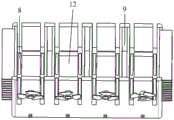
Fig. 1 is a schematic structural diagram of a multi-cooling-mode power battery heat dissipation device according to an embodiment of the present invention;
FIG. 2 is a schematic structural diagram of the high temperature bonding of the heat pipe and the copper plate according to one embodiment of the present invention;
FIG. 3 is a schematic structural diagram of a heat dissipation box and a channel groove according to an embodiment of the present invention;
FIG. 4 is a schematic view of a heat dissipation hole according to an embodiment of the present invention;
fig. 5 is a schematic structural diagram of a battery storage tank according to an embodiment of the present invention.
Description of reference numerals: 1-a power battery; 2-air cooling flow channel; 3-a heat dissipation fan; 4-radiating fins; 5-a straight heat pipe; 6-elbow heat pipe; 7-heat dissipation holes; 8-a runner groove; 9-a heat dissipation box; 11-a battery tab; 12-a battery storage tank; 13-bottom plate.
Detailed Description
In order to make the objects, technical solutions and advantages of the present invention more apparent, the present invention is further described in detail below with reference to embodiments thereof; it should be understood that the specific embodiments described herein are merely illustrative of the invention and are not intended to limit the invention. Other systems, methods, and/or features of the present embodiments will become apparent to those skilled in the art upon review of the following detailed description. It is intended that all such additional systems, methods, features and advantages be included within this description, be within the scope of the invention, and be protected by the accompanying claims. Additional features of the disclosed embodiments are described in, and will be apparent from, the detailed description that follows.
The same or similar reference numerals in the drawings of the embodiments of the present invention correspond to the same or similar components; in the description of the present invention, it should be understood that if there is an orientation or positional relationship indicated by the terms "upper", "lower", "left", "right", etc. based on the orientation or positional relationship shown in the drawings, it is only for convenience of describing the present invention and simplifying the description, but it is not intended to indicate or imply that the device or component referred to must have a specific orientation, be constructed in a specific orientation, and be operated, and therefore, the terms describing the positional relationship in the drawings are only used for illustrative purposes and are not to be construed as limiting the present patent, and the specific meaning of the terms described above will be understood by those of ordinary skill in the art according to the specific circumstances.
The invention relates to a multi-cooling mode power battery heat dissipation device, which explains the following embodiments according to the description of the attached drawings:
the first embodiment is as follows:
a multi-cooling mode power battery heat dissipation device comprises a heat dissipation box 9, a box cover used for sealing the heat dissipation box 9, a plurality of battery storage grooves 12 arranged in the heat dissipation box 9, an air cooling module and a heat pipe cooling module; the heat dissipation box 9 is internally provided with a bottom plate 13 for supporting the battery storage groove 12; the battery storage grooves 12 are uniformly distributed in the heat dissipation box 9, each battery storage groove 12 is provided with a notch, one end, without the notch, of each battery storage groove 12 is connected with the bottom plate 13, and each battery storage groove 12 is used for accommodating the power battery 1; the air cooling module is arranged around two sides of the battery storage groove 12 and is used for cooling the power battery 1 in air; the heat pipe cooling module is connected to the bottom of the heat dissipation box 9 and the box cover and used for carrying out heat pipe cooling on the power battery 1.
The bottom plate 13 is made of copper, specifically, a copper plate, and the box cover is also provided with a copper plate for heat transfer.
The air cooling module comprises an air cooling runner 2 and a runner groove 8; the air cooling flow channel 2 is positioned on two sides of the battery storage groove 12 and penetrates through the heat dissipation box 9; the runner groove 8 is arranged on the bottom plate 13 in a manner of being matched with the air cooling runner 2.
The heat pipe cooling module comprises a plurality of straight heat pipes 5 and a plurality of elbow heat pipes 6; one part of the plurality of straight heat pipes 5 is connected to the bottom plate 13, and the other part is connected to the inside of the box cover; one part of the elbow heat pipe 6 is connected to the bottom plate 13, and the other part is connected to the inside of the box cover.
The heat dissipation device also comprises heat dissipation fins 4, a heat dissipation fan 3 and heat dissipation holes 7; the radiating fins 4 are connected to two sides of the radiating box 9, and the plane of the radiating fins 4 is perpendicular to the straight line formed by connecting the battery storage grooves 12; the heat dissipation fan 3 is matched with the battery storage groove 12 and is arranged on one side of the heat dissipation box 9; the heat dissipation holes 7 are formed in the outer surfaces of the heat dissipation box 9 and the box cover.
The heat dissipation box comprises two battery separators.
The air cooling runner 2 runs through and sets up in power battery both sides, and air cooling runner 2 lower surface and battery hollow partition outer wall are provided with the runner recess 8 that is the rectangle through the little manufacturing process in surface. The radiating fins 4 are fixed at one end of the two outermost battery separators, and the battery storage groove 12 is arranged at the bottom of the radiating system. The copper plate is arranged above the power battery pack 1 in a penetrating mode, and part of the straight heat pipes 5 and the elbow heat pipes 6 are arranged in the area range of the tabs 11 of the power battery and are bonded to the surface of the copper plate through high-temperature glue. The copper plate is arranged below the battery storage groove 12 in a penetrating mode, the straight heat pipe 5 is arranged in the range of the bottom area of the power battery 1, and the straight heat pipe is bonded to the surface of the copper plate through high-temperature glue. The heat radiation fan 3 is disposed at the center of one side of the heat radiation system.
The air cooling flow channel 2 is arranged on two sides of the power battery 1 in a penetrating mode. The lower surface of the air cooling runner 2 and the outer wall of the battery separator are provided with rectangular runner grooves 8 through a surface micro-manufacturing process. The flow channel groove 8 can convert the introduced cooling gas from a laminar flow state to a turbulent flow state, and the gas needs to extract heat generated by the power battery to form turbulent flow based on energy consumption of turbulent flow formed by the gas, so that the gas flows to the outside of the power battery.
The radiating fins 4 are fixed on the outer walls of one ends of the two outermost battery separators.
The cooling fan 3 is arranged in the center of one side of the cooling system, and the rotating range of the cooling fan 3 is arranged in the distance between two adjacent air cooling runners 2. The flow of the air cooling fluid is accelerated by the heat radiation fan 3, thereby enhancing the heat radiation strength.
The copper pass through the setting respectively power battery utmost point ear 11 with power battery hold groove 12, and then with power battery 1 just begin to work the gathering the heat transfer of battery utmost point ear 11 to the copper, and with power battery 1 after working for a long time the gathering in power battery 1 in the heat transfer of below to the copper.
The part of the straight heat pipe 5 and the elbow heat pipe 6 are arranged in the area range of the power battery tab 11 and are bonded on the surface of the copper plate through high-temperature glue. The straight heat pipe 5 is arranged in the lower bottom area range of the power battery 1 and is bonded on the surface of the copper plate through high-temperature glue. The copper plate is fixedly bonded with the straight heat pipe 5 and the elbow heat pipe 6, so that heat generated by the power battery 1 is transferred to the outside.
The box cover, the lower bottom cover and the side walls of the heat dissipation device are provided with the heat dissipation holes 7.
Example two:
a multi-cooling mode power battery heat dissipation device comprises a heat dissipation box 9, a box cover used for sealing the heat dissipation box 9, a plurality of battery storage grooves 12 arranged in the heat dissipation box 9, an air cooling module and a heat pipe cooling module; the heat dissipation box 9 is internally provided with a bottom plate 13 for supporting the battery storage groove 12; the battery storage grooves 12 are uniformly distributed in the heat dissipation box 9, each battery storage groove 12 is provided with a notch, one end, without the notch, of each battery storage groove 12 is connected with the bottom plate 13, and each battery storage groove 12 is used for accommodating the power battery 1; the air cooling module is arranged around two sides of the battery storage groove 12 and is used for cooling the power battery 1 in air; the heat pipe cooling module is connected to the bottom of the heat dissipation box 9 and the box cover and used for carrying out heat pipe cooling on the power battery 1.
The bottom plate 13 is made of copper, specifically, a copper plate, and the box cover is also provided with a copper plate for heat transfer.
The air cooling module comprises an air cooling runner 2 and a runner groove 8; the air cooling flow channel 2 is positioned on two sides of the battery storage groove 12 and penetrates through the heat dissipation box 9; the runner groove 8 is arranged on the bottom plate 13 in a manner of being matched with the air cooling runner 2.
The heat pipe cooling module comprises a plurality of straight heat pipes 5 and a plurality of elbow heat pipes 6; one part of the plurality of straight heat pipes 5 is connected to the bottom plate 13, and the other part is connected to the inside of the box cover; one part of the elbow heat pipe 6 is connected to the bottom plate 13, and the other part is connected to the inside of the box cover.
The heat dissipation device also comprises heat dissipation fins 4, a heat dissipation fan 3 and heat dissipation holes 7; the radiating fins 4 are connected to two sides of the radiating box 9, and the plane of the radiating fins 4 is perpendicular to the straight line formed by connecting the battery storage grooves 12; the heat dissipation fan 3 is matched with the battery storage groove 12 and is arranged on one side of the heat dissipation box 9; the heat dissipation holes 7 are formed in the outer surfaces of the heat dissipation box 9 and the box cover.
The heat dissipation case 9 includes a battery separator.
The air cooling runner 2 runs through and sets up in power battery both sides, and air cooling runner 2 lower surface and battery hollow partition outer wall are provided with the runner recess 8 that is the rectangle through the little manufacturing process in surface. The radiating fins 4 are fixed at one end of the two outermost battery separators, and the battery storage groove 12 is arranged at the bottom of the radiating system. The copper plate is arranged above the power battery pack 1 in a penetrating mode, and part of the straight heat pipes 5 and the elbow heat pipes 6 are arranged in the area range of the tabs 11 of the power battery and are bonded to the surface of the copper plate through high-temperature glue. The copper plate is arranged below the battery storage groove 12 in a penetrating mode, the straight heat pipe 5 is arranged in the range of the bottom area of the power battery 1, and the straight heat pipe is bonded to the surface of the copper plate through high-temperature glue. The heat radiation fan 3 is disposed at the center of one side of the heat radiation system.
The air cooling flow channel 2 is arranged on two sides of the power battery 1 in a penetrating mode. The lower surface of the air cooling runner 2 and the outer wall of the battery separator are provided with rectangular runner grooves 8 through a surface micro-manufacturing process. The flow channel groove 8 can convert the introduced cooling gas from a laminar flow state to a turbulent flow state, and the gas needs to extract heat generated by the power battery to form turbulent flow based on energy consumption of turbulent flow formed by the gas, so that the gas flows to the outside of the power battery.
The radiating fins 4 are fixed on the outer walls of one ends of the two outermost battery separators.
The cooling fan 3 is arranged in the center of one side of the cooling system, and the rotating range of the cooling fan 3 is arranged in the distance between two adjacent air cooling runners 2. The flow of the air cooling fluid is accelerated by the heat radiation fan 3, thereby enhancing the heat radiation strength.
The copper pass through the setting respectively power battery utmost point ear 11 with power battery hold groove 12, and then with power battery 1 just begin to work the gathering the heat transfer of battery utmost point ear 11 to the copper, and with power battery 1 after working for a long time the gathering in power battery 1 in the heat transfer of below to the copper.
The part of the straight heat pipe 5 and the elbow heat pipe 6 are arranged in the area range of the power battery tab 11 and are bonded on the surface of the copper plate through high-temperature glue. The straight heat pipe 5 is arranged in the lower bottom area range of the power battery 1 and is bonded on the surface of the copper plate through high-temperature glue. The copper plate is fixedly bonded with the straight heat pipe 5 and the elbow heat pipe 6, so that heat generated by the power battery 1 is transferred to the outside.
The box cover, the lower bottom cover and the side walls of the heat dissipation device are provided with the heat dissipation holes 7.
Preferably, the heat dissipation box 9 is any one of an aluminum alloy box, a cold-rolled plate box, a hot-rolled plate box and a polymer box.
Preferably, a plurality of handles are further mounted on the outer wall surface of the box body of the heat dissipation box 9, so that the heat dissipation system of the power battery pack can be conveniently moved.
Preferably, the battery storage tank 12 is made of any one of aluminum alloy, cold-rolled sheet, hot-rolled sheet, and polymer sheet. And fixing a plurality of matched power batteries through the battery storage groove 12 to obtain a power battery pack.
Preferably, the power battery 1 installed in the battery storage tank 12 is one of a polymer soft package, a ternary lithium ion cylinder, a square aluminum shell, a lithium iron phosphate cylinder, a square aluminum shell, and the like.
Preferably, the heat collecting part (not shown in the figure) comprises a first bottom plate and a plurality of first grid plates, the first bottom plate is horizontally arranged, the first grid plates extend upwards from the first bottom plate, the first grid plates are perpendicular to the surface of the first bottom plate, first plug holes (not shown in the figure) are formed in the first grid plates, the heat conducting part is inserted into the first plug holes, the first grid plates abut against the lower surface of the power battery pack mounting box, a large amount of heat generated by the power battery pack can be prevented from having no convection space, heat moving is facilitated by means of gaps of the first grid plates, and in entering the first grid plate forming space, the contact area between the heat and the heat collecting part is increased, and the heat collecting effect is improved.
Preferably, the heat sink (not shown) includes a second bottom plate and a plurality of second grid plates, the second grid plates extend inward from the surface of the second bottom plate and are perpendicular to the inner surface of the second bottom plate, second insertion holes (not shown) are formed in the second grid plates, the other ends of the heat conducting members are inserted into the second insertion holes, and the fan is detachably mounted on the outer surface of the second bottom plate.
Preferably, the heat collecting member and/or the heat dissipating member is an aluminum profile. The aluminum profile has the characteristics of good heat conduction effect and difficulty in corrosion.
Preferably, the heat conducting member is any one of a wire mesh structure copper pipe, a fiber structure copper pipe, and a groove structure copper pipe. The copper pipes with the structures have good heat conduction effects, and can quickly conduct heat collected by the heat collection part to the heat dissipation part.
According to the multi-cooling-mode power battery heat dissipation device, on one hand, heat generated by the power battery pack is conducted to the position near the fan through the heat conduction element, and the heat of the power battery pack can be timely dissipated to the outside of the box body under the action of the fan, so that the temperature of the power battery pack is effectively reduced, the power battery is guaranteed to work at a relatively constant temperature, and the service efficiency and the service life of the battery are improved; on the other hand, because of the existence of the heat dissipation assembly, the power battery pack can be completely and hermetically installed in the power battery pack installation box, dust or moisture is effectively prevented from entering the battery pack, and the safety of the battery pack is improved.
Furthermore, in this embodiment, the battery storage tank further includes an automatic control module (not shown), a temperature sensing element (not shown) for monitoring the temperature of the power battery is further installed in the battery storage tank, and one end of the automatic control module is connected to the temperature sensing element, and the other end of the automatic control module is connected to the cooling fan, so that the automatic control module can adjust the rotation speed of the cooling fan according to the temperature change condition monitored by the temperature sensing element in the battery storage tank, and the temperature of the cooling system of the power battery is controllable.
Example three:
a multi-cooling mode power battery heat dissipation device comprises a heat dissipation box 9, a box cover used for sealing the heat dissipation box 9, a plurality of battery storage grooves 12 arranged in the heat dissipation box 9, an air cooling module and a heat pipe cooling module; the heat dissipation box 9 is internally provided with a bottom plate 13 for supporting the battery storage groove 12; the battery storage grooves 12 are uniformly distributed in the heat dissipation box 9, each battery storage groove 12 is provided with a notch, one end, without the notch, of each battery storage groove 12 is connected with the bottom plate 13, and each battery storage groove 12 is used for accommodating the power battery 1; the air cooling module is arranged around two sides of the battery storage groove 12 and is used for cooling the power battery 1 in air; the heat pipe cooling module is connected to the bottom of the heat dissipation box 9 and the box cover and used for carrying out heat pipe cooling on the power battery 1.
The bottom plate 13 is made of copper, specifically, a copper plate, and the box cover is also provided with a copper plate for heat transfer.
The air cooling module comprises an air cooling runner 2 and a runner groove 8; the air cooling flow channel 2 is positioned on two sides of the battery storage groove 12 and penetrates through the heat dissipation box 9; the runner groove 8 is arranged on the bottom plate 13 in a manner of being matched with the air cooling runner 2.
The heat pipe cooling module comprises a plurality of straight heat pipes 5 and a plurality of elbow heat pipes 6; one part of the plurality of straight heat pipes 5 is connected to the bottom plate 13, and the other part is connected to the inside of the box cover; one part of the elbow heat pipe 6 is connected to the bottom plate 13, and the other part is connected to the inside of the box cover.
The heat dissipation device also comprises heat dissipation fins 4, a heat dissipation fan 3 and heat dissipation holes 7; the radiating fins 4 are connected to two sides of the radiating box 9, and the plane of the radiating fins 4 is perpendicular to the straight line formed by connecting the battery storage grooves 12; the heat dissipation fan 3 is matched with the battery storage groove 12 and is arranged on one side of the heat dissipation box 9; the heat dissipation holes 7 are formed in the outer surfaces of the heat dissipation box 9 and the box cover.
The heat dissipation case 9 includes a battery separator.
The air cooling runner 2 runs through and sets up in power battery both sides, and air cooling runner 2 lower surface and battery hollow partition outer wall are provided with the runner recess 8 that is the rectangle through the little manufacturing process in surface. The radiating fins 4 are fixed at one end of the two outermost battery separators, and the battery storage groove 12 is arranged at the bottom of the radiating system. The copper plate is arranged above the power battery pack 1 in a penetrating mode, and part of the straight heat pipes 5 and the elbow heat pipes 6 are arranged in the area range of the tabs 11 of the power battery and are bonded to the surface of the copper plate through high-temperature glue. The copper plate is arranged below the battery storage groove 12 in a penetrating mode, the straight heat pipe 5 is arranged in the range of the bottom area of the power battery 1, and the straight heat pipe is bonded to the surface of the copper plate through high-temperature glue. The heat radiation fan 3 is disposed at the center of one side of the heat radiation system.
The air cooling flow channel 2 is arranged on two sides of the power battery 1 in a penetrating mode. The lower surface of the air cooling runner 2 and the outer wall of the battery separator are provided with rectangular runner grooves 8 through a surface micro-manufacturing process. The flow channel groove 8 can convert the introduced cooling gas from a laminar flow state to a turbulent flow state, and the gas needs to extract heat generated by the power battery to form turbulent flow based on energy consumption of turbulent flow formed by the gas, so that the gas flows to the outside of the power battery.
The radiating fins 4 are fixed on the outer walls of one ends of the two outermost battery separators.
The cooling fan 3 is arranged in the center of one side of the cooling system, and the rotating range of the cooling fan 3 is arranged in the distance between two adjacent air cooling runners 2. The flow of the air cooling fluid is accelerated by the heat radiation fan 3, thereby enhancing the heat radiation strength.
The copper pass through the setting respectively power battery utmost point ear 11 with power battery hold groove 12, and then with power battery 1 just begin to work the gathering the heat transfer of battery utmost point ear 11 to the copper, and with power battery 1 after working for a long time the gathering in power battery 1 in the heat transfer of below to the copper.
The part of the straight heat pipe 5 and the elbow heat pipe 6 are arranged in the area range of the power battery tab 11 and are bonded on the surface of the copper plate through high-temperature glue. The straight heat pipe 5 is arranged in the lower bottom area range of the power battery 1 and is bonded on the surface of the copper plate through high-temperature glue. The copper plate is fixedly bonded with the straight heat pipe 5 and the elbow heat pipe 6, so that heat generated by the power battery 1 is transferred to the outside.
The box cover, the lower bottom cover and the side walls of the heat dissipation device are provided with the heat dissipation holes 7.
Preferably, the heat dissipation box 9 is any one of an aluminum alloy box, a cold-rolled plate box, a hot-rolled plate box and a polymer box.
Preferably, a plurality of handles are further mounted on the outer wall surface of the box body of the heat dissipation box 9, so that the heat dissipation system of the power battery pack can be conveniently moved.
Preferably, the battery storage tank 12 is made of any one of aluminum alloy, cold-rolled sheet, hot-rolled sheet, and polymer sheet. And fixing a plurality of matched power batteries through the battery storage groove 12 to obtain a power battery pack.
Preferably, the power battery 1 installed in the battery storage tank 12 is one of a polymer soft package, a ternary lithium ion cylinder, a square aluminum shell, a lithium iron phosphate cylinder, a square aluminum shell, and the like.
Preferably, the heat collecting part (not shown in the figure) comprises a first bottom plate and a plurality of first grid plates, the first bottom plate is horizontally arranged, the first grid plates extend upwards from the first bottom plate, the first grid plates are perpendicular to the surface of the first bottom plate, first plug holes (not shown in the figure) are formed in the first grid plates, the heat conducting part is inserted into the first plug holes, the first grid plates abut against the lower surface of the power battery pack mounting box, a large amount of heat generated by the power battery pack can be prevented from having no convection space, heat moving is facilitated by means of gaps of the first grid plates, and in entering the first grid plate forming space, the contact area between the heat and the heat collecting part is increased, and the heat collecting effect is improved.
Preferably, the heat sink (not shown) includes a second bottom plate and a plurality of second grid plates, the second grid plates extend inward from the surface of the second bottom plate and are perpendicular to the inner surface of the second bottom plate, second insertion holes (not shown) are formed in the second grid plates, the other ends of the heat conducting members are inserted into the second insertion holes, and the fan is detachably mounted on the outer surface of the second bottom plate.
Preferably, the heat collecting member and/or the heat dissipating member is an aluminum profile. The aluminum profile has the characteristics of good heat conduction effect and difficulty in corrosion.
Preferably, the heat conducting member is any one of a wire mesh structure copper pipe, a fiber structure copper pipe, and a groove structure copper pipe. The copper pipes with the structures have good heat conduction effects, and can quickly conduct heat collected by the heat collection part to the heat dissipation part.
According to the multi-cooling-mode power battery heat dissipation device, on one hand, heat generated by the power battery pack is conducted to the position near the fan through the heat conduction element, and the heat of the power battery pack can be timely dissipated to the outside of the box body under the action of the fan, so that the temperature of the power battery pack is effectively reduced, the power battery is guaranteed to work at a relatively constant temperature, and the service efficiency and the service life of the battery are improved; on the other hand, because of the existence of the heat dissipation assembly, the power battery pack can be completely and hermetically installed in the power battery pack installation box, dust or moisture is effectively prevented from entering the battery pack, and the safety of the battery pack is improved.
Furthermore, in this embodiment, the battery storage tank further includes an automatic control module (not shown), a temperature sensing element (not shown) for monitoring the temperature of the power battery is further installed in the battery storage tank, and one end of the automatic control module is connected to the temperature sensing element, and the other end of the automatic control module is connected to the cooling fan, so that the automatic control module can adjust the rotation speed of the cooling fan according to the temperature change condition monitored by the temperature sensing element in the battery storage tank, and the temperature of the cooling system of the power battery is controllable.
The power battery heat dissipation device of the embodiment comprises a battery storage tank and a thermal management control system; the battery storage tank comprises a battery module shell, a battery monomer, a composite phase change material plate, a heat pipe, a heating device, a composite phase change material heat pipe coupling assembly and a cooling fan. Firstly, a plurality of battery monomers arranged in a battery module shell are adjacently arranged to form a battery pack, and a composite phase change material plate is clamped between the gap between every two adjacent battery monomers and the surface of the outermost battery in the width direction of the battery pack; the battery pack comprises a battery module shell, a battery pack and a composite phase-change material heat pipe coupling assembly, wherein the battery pack is provided with a plurality of battery packs, the battery packs are arranged on the battery pack shell, the battery packs are arranged on the battery packs, the heat pipes of the composite phase-change.
The thermal management control system comprises a fan controller, a heating controller, a temperature sensor and a programmable thermostat. And a temperature probe of the temperature sensor is arranged on the battery monomer, is connected with the programmable automatic temperature regulator and is used for monitoring the running temperature of the battery pack in real time. The heat radiation fan is connected with the programmable automatic temperature regulator through a fan controller, and the fan controller is used for controlling the fan to work; the heating device is connected with the programmable automatic temperature regulator through an electric heating controller, and the electric heating controller is used for controlling the heating device to work.
Further: the composite phase change material plate is formed by directly pressing paraffin/expanded graphite or paraffin/expanded graphite/polyethylene into a required size through a mould, or mechanically processing the pressed composite phase change material plate into the required size.
The preparation method of the composite phase-change material heat pipe coupling component comprises the following steps: and symmetrically grooving the two composite phase change material plates according to the size and the bent shape of the pulsating heat pipe, then placing the heat pipe in the grooved channel, and finally combining the two composite phase change material plates into a composite phase change material heat pipe coupling assembly, wherein the whole assembly is tightly combined to reduce the contact thermal resistance. And the contact surfaces of the two composite phase change material plates and the contact surfaces of the heat pipe and the composite phase change material plates are coated with a heat conduction adhesive and a double-sided high-heat-conductivity graphite film or are directly subjected to mechanical compression bonding.
Further: the heating device is an electric heating rod, an electric heating film, an electric heating wire or a heating system connected with the whole vehicle. The heating part is tightly combined with the heat pipe, and heat is transferred to the phase-change material through the heat pipe, so that the battery pack is heated.
Further: the programmable thermostat is provided with a chip, and a program is written to process signals transmitted by the temperature sensor to determine whether to start the fan controller and the electric heating controller.
The working process of the power battery thermal management system with the efficient heat dissipation and heating functions is as follows.
1) Under the normal operating mode: the battery in the battery box generates a large amount of heat when working, and the heat is absorbed by the phase change material in the form of latent heat or sensible heat through the contact interface of the battery and the composite phase change material plate. The accumulation of heat leads to the phase change material temperature to rise, when the temperature of the contact surface of heat pipe and composite phase change material board reaches heat pipe start temperature, will arouse heat pipe work, thereby the quick heat in the phase change material transmits external environment rapidly, thereby the temperature that makes the battery maintains in the best operating temperature scope, programmable thermostat passes through temperature sensor this moment and monitors battery electricity core, electricity core temperature is in control temperature range, fan controller does not have the response to this temperature scope, the fan is out of work promptly.
2) The working of the heat radiation fan: when the operation condition is worse, the phase-change material accumulates heat rapidly and the heat pipe loses insufficient heat, the battery temperature rises continuously, when the battery temperature reaches the maximum temperature t set by the programmable thermostatmaxThe fan controller can respond to the temperature sensor, the fan is controlled to work, forced air convection achieves the purpose of strengthening heat dissipation through a heat pipe section (condensation end) extending out of a shell of the battery box, the programmable automatic temperature regulator monitors the battery cell in real time through the temperature sensor until the temperature of the battery is reduced to a set fan stop working temperature t for cooling, and the fan stops working.
3) The heating device works: in winter or cold regions, the temperature of the battery is low, the requirement of low-temperature starting or continuous work cannot be met, and when the temperature of the battery reaches the lowest temperature value t set by the programmable thermostatminThe heating controller responds to the situation, so that the heating device is controlled to work, the heating device works at a heat pipe section (evaporation end) extending out of the shell of the battery box, heat enters the composite phase change material plate through the heat pipe, the temperature of the whole battery box body is increased, the programmable automatic temperature regulator monitors the battery core in real time through the temperature sensor until the temperature of the battery rises to a set working temperature t of the heating device, and the heating device stops working.
In summary, the invention provides a multi-cooling power battery heat dissipation device, compared with the prior art, the multi-cooling power battery heat dissipation device has a simple and reasonable structure, and performs surface micro-manufacturing on an air cooling channel, so that air cooling gas is converted from a laminar flow state to a turbulent flow state, the air cooling gas absorbs heat generated by battery operation, and the heat of the battery is further transferred to the outside of the battery. The copper plate is utilized to increase the contact area between the heat pipe and the battery tab and the lower bottom of the battery, improve the heat transfer efficiency of the heat dissipation system, enable the temperature distribution of the battery to be more uniform, reduce the number of the heat pipes and reduce the cost.
Although the invention has been described above with reference to various embodiments, it should be understood that many changes and modifications may be made without departing from the scope of the invention. That is, the methods, systems, and devices discussed above are examples. Various configurations may omit, substitute, or add various procedures or components as appropriate. For example, in alternative configurations, the methods may be performed in an order different than that described, and/or various components may be added, omitted, and/or combined. Moreover, features described with respect to certain configurations may be combined in various other configurations, as different aspects and elements of the configurations may be combined in a similar manner. Further, elements therein may be updated as technology evolves, i.e., many elements are examples and do not limit the scope of the disclosure or claims.
Specific details are given in the description to provide a thorough understanding of the exemplary configurations including implementations. However, configurations may be practiced without these specific details, e.g., well-known circuits, processes, algorithms, structures, and techniques have been shown without unnecessary detail in order to avoid obscuring the configurations. This description provides example configurations only, and does not limit the scope, applicability, or configuration of the claims. Rather, the foregoing description of the configurations will provide those skilled in the art with an enabling description for implementing the described techniques. Various changes may be made in the function and arrangement of elements without departing from the spirit or scope of the disclosure.
It is intended that the foregoing detailed description be regarded as illustrative rather than limiting, and that it be understood that it is the following claims, including all equivalents, that are intended to define the spirit and scope of this invention. The above examples are to be construed as merely illustrative and not limitative of the remainder of the disclosure. After reading the description of the invention, the skilled person can make various changes or modifications to the invention, and these equivalent changes and modifications also fall into the scope of the invention defined by the claims.
Claims (2)
1. The multi-cooling mode power battery heat dissipation device is characterized by comprising a heat dissipation box, a box cover for sealing the heat dissipation box, a plurality of battery storage grooves arranged in the heat dissipation box, an air cooling module and a heat pipe cooling module; wherein,
the heat dissipation box is internally provided with a bottom plate for supporting the battery storage groove;
the battery storage grooves are uniformly distributed in the heat dissipation box and are provided with a notch, one end of each battery storage groove, which is not provided with the notch, is connected with the bottom plate, and the battery storage grooves are used for accommodating power batteries;
the air cooling module is arranged around two sides of the battery storage groove and used for cooling the power battery in air;
the heat pipe cooling module is connected to the bottom of the heat dissipation box and the box cover and used for carrying out heat pipe cooling on the power battery;
the heat dissipation box comprises two battery separators;
the air cooling module comprises an air cooling runner and a runner groove;
the air cooling flow channel is positioned on two sides of the battery storage groove and penetrates through the heat dissipation box;
the runner groove is arranged on the bottom plate in a manner of being matched with the air cooling runner;
the lower surface of the air cooling runner and the outer wall of the battery separator are provided with rectangular runner grooves through a surface micro-manufacturing process;
the heat pipe cooling module comprises a plurality of straight heat pipes and a plurality of elbow heat pipes; wherein,
one part of the plurality of straight heat pipes is connected to the bottom plate, and the other part of the plurality of straight heat pipes is connected to the inside of the box cover;
one part of the elbow heat pipe is connected to the bottom plate, and the other part of the elbow heat pipe is connected to the inside of the box cover;
the heat dissipation device further comprises a heat collection part, the heat collection part comprises a first bottom plate and a plurality of first grid plates, the first bottom plate is horizontally arranged, the first grid plates extend upwards from the first bottom plate, the first grid plates are perpendicular to the surface of the first bottom plate, first inserting holes are formed in the first grid plates, the heat conduction part is inserted into the first inserting holes, and the first grid plates abut against the lower surface of the bottom plate.
2. The multi-cooling power battery heat dissipation device of claim 1, further comprising heat dissipation fins, heat dissipation fans, heat dissipation holes;
the radiating fins are connected to two sides of the radiating box, and the planes of the radiating fins are perpendicular to straight lines formed by connecting the battery storage grooves;
the heat dissipation fan is matched with the battery storage groove and arranged on one side of the heat dissipation box;
the heat dissipation holes are formed in the outer surfaces of the heat dissipation box and the box cover.
Priority Applications (1)
| Application Number | Priority Date | Filing Date | Title |
|---|---|---|---|
| CN201910826630.7A CN110518309B (en) | 2019-09-03 | 2019-09-03 | Multi-cooling-mode power battery heat dissipation device |
Applications Claiming Priority (1)
| Application Number | Priority Date | Filing Date | Title |
|---|---|---|---|
| CN201910826630.7A CN110518309B (en) | 2019-09-03 | 2019-09-03 | Multi-cooling-mode power battery heat dissipation device |
Publications (2)
| Publication Number | Publication Date |
|---|---|
| CN110518309A CN110518309A (en) | 2019-11-29 |
| CN110518309B true CN110518309B (en) | 2021-01-26 |
Family
ID=68629362
Family Applications (1)
| Application Number | Title | Priority Date | Filing Date |
|---|---|---|---|
| CN201910826630.7A Expired - Fee Related CN110518309B (en) | 2019-09-03 | 2019-09-03 | Multi-cooling-mode power battery heat dissipation device |
Country Status (1)
| Country | Link |
|---|---|
| CN (1) | CN110518309B (en) |
Families Citing this family (4)
| Publication number | Priority date | Publication date | Assignee | Title |
|---|---|---|---|---|
| CN111192988B (en) * | 2020-01-10 | 2021-05-11 | 山东科技大学 | Novel battery box with internal thermal management system for electric automobile and working method of novel battery box |
| CN111367381A (en) * | 2020-03-31 | 2020-07-03 | 广东金宇恒软件科技有限公司 | Emergency protection system for public financial people large budget online networking monitoring system |
| CN113054314B (en) * | 2021-03-16 | 2022-09-13 | 岭南师范学院 | Automobile power battery enhanced heat transfer system under action of multiple heat dissipation modes |
| CN113555623B (en) * | 2021-09-23 | 2021-12-24 | 江苏久祥汽车电器集团有限公司 | Heat radiation structure of group battery |
Citations (7)
| Publication number | Priority date | Publication date | Assignee | Title |
|---|---|---|---|---|
| JP2013073722A (en) * | 2011-09-27 | 2013-04-22 | Furukawa Electric Co Ltd:The | Battery temperature adjusting unit and battery temperature adjusting apparatus |
| CN205282608U (en) * | 2016-01-08 | 2016-06-01 | 鸥瑞智诺能源科技(天津)有限公司 | Lithium battery box box that dispels heat |
| CN107634164A (en) * | 2017-09-29 | 2018-01-26 | 湘潭大学 | A kind of battery thermal management system combined based on microchannel thermotube and phase-change material |
| CN207967241U (en) * | 2018-03-08 | 2018-10-12 | 苏州巨果电子科技有限公司 | A kind of radiating device of battery pack |
| CN208849041U (en) * | 2018-09-27 | 2019-05-10 | 华南理工大学 | The power battery thermal management system of ultrathin aluminum strip heat pipe combination composite phase-change material |
| CN110071348A (en) * | 2019-05-10 | 2019-07-30 | 佛山科学技术学院 | Based on the cooling power battery thermal management system of composite phase-change material and its application |
| CN110120564A (en) * | 2018-02-06 | 2019-08-13 | 盾安汽车热管理科技有限公司 | A kind of power battery thermal management system |
Family Cites Families (1)
| Publication number | Priority date | Publication date | Assignee | Title |
|---|---|---|---|---|
| CN206098509U (en) * | 2016-11-03 | 2017-04-12 | 山东威林特新能源科技有限公司 | Ventilation unit of lithium cell group |
-
2019
- 2019-09-03 CN CN201910826630.7A patent/CN110518309B/en not_active Expired - Fee Related
Patent Citations (7)
| Publication number | Priority date | Publication date | Assignee | Title |
|---|---|---|---|---|
| JP2013073722A (en) * | 2011-09-27 | 2013-04-22 | Furukawa Electric Co Ltd:The | Battery temperature adjusting unit and battery temperature adjusting apparatus |
| CN205282608U (en) * | 2016-01-08 | 2016-06-01 | 鸥瑞智诺能源科技(天津)有限公司 | Lithium battery box box that dispels heat |
| CN107634164A (en) * | 2017-09-29 | 2018-01-26 | 湘潭大学 | A kind of battery thermal management system combined based on microchannel thermotube and phase-change material |
| CN110120564A (en) * | 2018-02-06 | 2019-08-13 | 盾安汽车热管理科技有限公司 | A kind of power battery thermal management system |
| CN207967241U (en) * | 2018-03-08 | 2018-10-12 | 苏州巨果电子科技有限公司 | A kind of radiating device of battery pack |
| CN208849041U (en) * | 2018-09-27 | 2019-05-10 | 华南理工大学 | The power battery thermal management system of ultrathin aluminum strip heat pipe combination composite phase-change material |
| CN110071348A (en) * | 2019-05-10 | 2019-07-30 | 佛山科学技术学院 | Based on the cooling power battery thermal management system of composite phase-change material and its application |
Also Published As
| Publication number | Publication date |
|---|---|
| CN110518309A (en) | 2019-11-29 |
Similar Documents
| Publication | Publication Date | Title |
|---|---|---|
| CN110518309B (en) | Multi-cooling-mode power battery heat dissipation device | |
| CN106960988B (en) | Power lithium battery thermal management system | |
| WO2019001466A1 (en) | Cylindrical lithium ion battery | |
| CN207818842U (en) | A kind of power battery heat-radiating device | |
| CN111029681B (en) | Tube sheet type heat pipe type power battery heat management module structure | |
| CN212434707U (en) | Blade battery package thermal management system based on micro heat pipe array | |
| CN109742282A (en) | A kind of cooling micro-channel heat exchanger of new energy battery | |
| CN210074099U (en) | Battery module, battery pack, electric vehicle and power grid system | |
| CN216389523U (en) | BDU heat radiation structure of automobile battery pack | |
| CN205723860U (en) | A kind of battery modules with heat management device | |
| CN212412130U (en) | Power battery thermal management system with cold and hot working condition temperature regulation function | |
| CN112510285A (en) | Heat dissipation method and device for vehicle battery module | |
| CN210110999U (en) | Power battery heat radiation structure | |
| CN110707259A (en) | High-protection-level air-cooled lithium battery pack thermal management system and method | |
| WO2019001467A1 (en) | Lithium ion pouch cell | |
| EP4273996A1 (en) | Battery cell and battery module comprising same | |
| WO2019001468A1 (en) | Lithium-ion power battery | |
| CN212340032U (en) | Power battery assembly and heat exchanger thereof | |
| CN108807730B (en) | Layered electric automobile battery pack | |
| CN208028117U (en) | A kind of series connection of cylindrical battery and parallel-connection structure | |
| CN113871746A (en) | Battery and battery module | |
| CN116111232B (en) | Self-circulation constant temperature battery control system | |
| WO2019001469A1 (en) | Thermally conductive lithium ion battery | |
| WO2019001470A1 (en) | Lithium ion power battery | |
| CN220796954U (en) | Battery pack with heat-conducting plate and energy storage container |
Legal Events
| Date | Code | Title | Description |
|---|---|---|---|
| PB01 | Publication | ||
| PB01 | Publication | ||
| SE01 | Entry into force of request for substantive examination | ||
| SE01 | Entry into force of request for substantive examination | ||
| GR01 | Patent grant | ||
| GR01 | Patent grant | ||
| CF01 | Termination of patent right due to non-payment of annual fee | ||
| CF01 | Termination of patent right due to non-payment of annual fee |
Granted publication date: 20210126 |