CN110517841B - A kind of placement protection equipment for nuclear magnetic resonance superconducting magnet - Google Patents
A kind of placement protection equipment for nuclear magnetic resonance superconducting magnet Download PDFInfo
- Publication number
- CN110517841B CN110517841B CN201910605433.2A CN201910605433A CN110517841B CN 110517841 B CN110517841 B CN 110517841B CN 201910605433 A CN201910605433 A CN 201910605433A CN 110517841 B CN110517841 B CN 110517841B
- Authority
- CN
- China
- Prior art keywords
- superconducting magnet
- magnetic resonance
- nuclear magnetic
- frame
- drive
- Prior art date
- Legal status (The legal status is an assumption and is not a legal conclusion. Google has not performed a legal analysis and makes no representation as to the accuracy of the status listed.)
- Active
Links
- 238000005481 NMR spectroscopy Methods 0.000 title claims abstract description 102
- 230000001681 protective effect Effects 0.000 claims abstract description 69
- 230000005540 biological transmission Effects 0.000 claims abstract description 54
- 238000000034 method Methods 0.000 claims description 18
- 238000009434 installation Methods 0.000 claims description 7
- 239000003381 stabilizer Substances 0.000 claims 1
- 125000006850 spacer group Chemical group 0.000 description 5
- 238000010586 diagram Methods 0.000 description 4
- 230000009286 beneficial effect Effects 0.000 description 2
- XEEYBQQBJWHFJM-UHFFFAOYSA-N Iron Chemical group [Fe] XEEYBQQBJWHFJM-UHFFFAOYSA-N 0.000 description 1
- 230000007547 defect Effects 0.000 description 1
- 238000012986 modification Methods 0.000 description 1
- 230000004048 modification Effects 0.000 description 1
- 238000013421 nuclear magnetic resonance imaging Methods 0.000 description 1
- 230000001568 sexual effect Effects 0.000 description 1
- 239000002887 superconductor Substances 0.000 description 1
- 230000007704 transition Effects 0.000 description 1
Images


Classifications
-
- G—PHYSICS
- G01—MEASURING; TESTING
- G01R—MEASURING ELECTRIC VARIABLES; MEASURING MAGNETIC VARIABLES
- G01R33/00—Arrangements or instruments for measuring magnetic variables
- G01R33/20—Arrangements or instruments for measuring magnetic variables involving magnetic resonance
- G01R33/28—Details of apparatus provided for in groups G01R33/44 - G01R33/64
- G01R33/38—Systems for generation, homogenisation or stabilisation of the main or gradient magnetic field
- G01R33/3802—Manufacture or installation of magnet assemblies; Additional hardware for transportation or installation of the magnet assembly or for providing mechanical support to components of the magnet assembly
-
- H—ELECTRICITY
- H01—ELECTRIC ELEMENTS
- H01F—MAGNETS; INDUCTANCES; TRANSFORMERS; SELECTION OF MATERIALS FOR THEIR MAGNETIC PROPERTIES
- H01F6/00—Superconducting magnets; Superconducting coils
Landscapes
- Physics & Mathematics (AREA)
- Condensed Matter Physics & Semiconductors (AREA)
- General Physics & Mathematics (AREA)
- Engineering & Computer Science (AREA)
- Power Engineering (AREA)
- Magnetic Resonance Imaging Apparatus (AREA)
- Superconductive Dynamoelectric Machines (AREA)
Abstract
本发明公开了一种核磁共振超导磁体用安置防护设备,可以解决现有的核磁共振超导磁体用安置防护设备在使用时,首先核磁共振超导磁体在被安置防护装置固定后的角度调整不方便,尤其是在进行小幅度的角度调整时,也存在角度调整不准确的问题,其次,无法保证既能够方便对核磁共振超导磁体进行角度调整,又能够保证超导磁体的稳定性的问题。包括支架以及安装在内部的防护架,所述支架侧壁上安装有电源,且所述支架底部设置有两个支脚,所述支架顶部固定安装有顶架,所述顶架侧壁上安装有驱动电机,所述驱动电机侧壁上连接有一根贯穿支架的传动轴,所述传动轴一端连接有驱动轮,所述支架顶部内壁上安装有液压泵。
The invention discloses a placement protection device for a nuclear magnetic resonance superconducting magnet, which can solve the problem of firstly adjusting the angle of the nuclear magnetic resonance superconducting magnet after being fixed by the placement protection device when the existing placement protection device for the nuclear magnetic resonance superconducting magnet is in use. It is inconvenient, especially when performing small-scale angle adjustment, there is also the problem of inaccurate angle adjustment. Secondly, it is impossible to ensure that the angle adjustment of the nuclear magnetic resonance superconducting magnet can be convenient and the stability of the superconducting magnet can be guaranteed. question. Including a bracket and a protective frame installed inside, a power supply is installed on the side wall of the bracket, two legs are arranged at the bottom of the bracket, a top frame is fixedly installed on the top of the bracket, and a side wall of the top frame is installed with A drive motor is connected to the side wall of the drive motor with a transmission shaft passing through the bracket, one end of the transmission shaft is connected with a driving wheel, and a hydraulic pump is installed on the inner wall of the top of the bracket.
Description
技术领域technical field
本发明涉及超导磁体安置防护领域,具体涉及一种核磁共振超导磁体用安置防护设备。The invention relates to the field of superconducting magnet placement protection, in particular to a placement protection device for nuclear magnetic resonance superconducting magnets.
背景技术Background technique
超导磁体是指低温下用具有高转变温度和临界磁场特别高的第二类超导体制成线圈的一种电磁体。它的主要特点是无导线电阻产生的电损耗,也没有因铁芯存在而产生的磁损耗,具有很强的实用价值,其中就包括用于核磁共振,超导磁体在用于核磁共振设备时,需要使用到安置防护设备对其进行保护,但是,现有的核磁共振超导磁体用安置防护设备在使用时仍存在一定缺陷,首先核磁共振超导磁体在被安置防护装置固定后的角度调整不方便,尤其是在进行小幅度的角度调整时,也存在角度调整不准确的问题,其次,无法保证既能够方便对核磁共振超导磁体进行角度调整,又能够保证超导磁体的稳定性。A superconducting magnet refers to an electromagnet made of a second type of superconductor with a high transition temperature and a particularly high critical magnetic field at low temperature. Its main feature is that there is no electrical loss caused by wire resistance, and no magnetic loss caused by the existence of the iron core. It has strong practical value, including the use of nuclear magnetic resonance and superconducting magnets when used in nuclear magnetic resonance equipment. , it is necessary to use placement protection equipment to protect it. However, the existing placement protection equipment for NMR superconducting magnets still has certain defects in use. First, the angle adjustment of the nuclear magnetic resonance superconducting magnet after being fixed by the placement protection device It is inconvenient, especially when performing small-amplitude angle adjustment, there is also the problem of inaccurate angle adjustment. Secondly, it cannot be guaranteed that the angle adjustment of the nuclear magnetic resonance superconducting magnet can be facilitated, and the stability of the superconducting magnet can be guaranteed.
公开号为CN107799264A的专利公开了一种高温超导磁体的固定架,对比文件中的固定架相当于本申请的安置防护装置,但是对比文件与本申请文相比,无法解决本申请文所提出的:现有的核磁共振超导磁体用安置防护设备在使用时,首先核磁共振超导磁体在被安置防护装置固定后的角度调整不方便,尤其是在进行小幅度的角度调整时,也存在角度调整不准确的问题,其次,无法保证既能够方便对核磁共振超导磁体进行角度调整,又能够保证超导磁体的稳定性。The patent with publication number CN107799264A discloses a fixing frame for a high temperature superconducting magnet. The fixing frame in the reference document is equivalent to the placement protection device of the present application, but the reference document cannot solve the problem proposed in the present application document compared with the present application document. When the existing NMR superconducting magnet placement protection equipment is in use, first of all, it is inconvenient to adjust the angle of the NMR superconducting magnet after being fixed by the placement protection device, especially when performing small-scale angle adjustment. The problem of inaccurate angle adjustment, and secondly, cannot guarantee that the angle adjustment of the nuclear magnetic resonance superconducting magnet can be facilitated, and the stability of the superconducting magnet can be guaranteed.
发明内容SUMMARY OF THE INVENTION
本发明的目的在于提供一种核磁共振超导磁体用安置防护设备,可以解决现有的核磁共振超导磁体用安置防护设备在使用时,首先核磁共振超导磁体在被安置防护装置固定后的角度调整不方便,尤其是在进行小幅度的角度调整时,也存在角度调整不准确的问题,其次,无法保证既能够方便对核磁共振超导磁体进行角度调整,又能够保证超导磁体的稳定性的问题。The purpose of the present invention is to provide a kind of placement protection device for nuclear magnetic resonance superconducting magnet, which can solve the problem that the existing placement protection device for nuclear magnetic resonance superconducting magnet is in use. The angle adjustment is inconvenient, especially when performing small-scale angle adjustment, there is also the problem of inaccurate angle adjustment. Secondly, it cannot be guaranteed that the angle adjustment of the nuclear magnetic resonance superconducting magnet can be convenient and the stability of the superconducting magnet can be guaranteed. sexual issues.
本发明的目的可以通过以下技术方案实现:The object of the present invention can be realized through the following technical solutions:
一种核磁共振超导磁体用安置防护设备,包括支架以及安装在内部的防护架,所述支架侧壁上安装有电源,且所述支架底部设置有两个支脚,所述支架顶部固定安装有顶架,所述顶架侧壁上安装有驱动电机,所述驱动电机侧壁上连接有一根贯穿支架的传动轴,所述传动轴一端连接有驱动轮,所述支架顶部内壁上安装有液压泵,所述液压泵侧壁上连接有两根液压伸缩顶杆,所述支架一侧外壁上安装有四个传送轮,且所述支架另一侧外壁上安装有四个与传送轮位置相对应的辅助轮,所述传送轮与辅助轮上均设置有环形槽,所述防护架安装在四个传送轮与四个辅助轮之间,安装所述传送轮的支架顶部侧壁上固定安装有两个侧板,两个所述侧板上均设置有一个滑槽,所述滑槽内部安装有可左右调整位置的张力轮,所述驱动轮与两个张力轮、四个传送轮之间缠绕有一根传送链;A nuclear magnetic resonance superconducting magnet placement protection device includes a bracket and a protective frame installed inside, a power supply is installed on the side wall of the bracket, two legs are arranged at the bottom of the bracket, and a top of the bracket is fixedly installed with a power supply. The top frame, a drive motor is installed on the side wall of the top frame, a drive shaft is connected to the side wall of the drive motor, and a drive shaft is connected to one end of the drive shaft, and a hydraulic pressure is installed on the inner wall of the top of the support Pump, two hydraulic telescopic ejector rods are connected to the side wall of the hydraulic pump, four transmission wheels are installed on the outer wall of one side of the bracket, and four transmission wheels are installed on the outer wall of the other side of the bracket. Corresponding auxiliary wheels, the transmission wheels and auxiliary wheels are provided with annular grooves, the protective frame is installed between the four transmission wheels and the four auxiliary wheels, and the top side walls of the brackets on which the transmission wheels are installed are fixedly installed There are two side plates, a chute is set on both of the side plates, and a tension wheel whose position can be adjusted left and right is installed inside the chute. There is a conveyor chain wrapped around it;
所述防护架两端侧壁上均安装有一个边环,所述边环上设置有两个固定座,两个所述固定座上均安装有一个用于将边环与防护架之间固定连接的螺钉,所述边环上安装有三个均匀分布的气泵,且所述边环内壁上安装有三个与气泵位置相对应的定位架,所述定位架与气泵之间通过两根第二气动伸缩杆相连接,所述定位架与气泵之间设置有收纳槽,所述收纳槽内部安装有一个轮座,所述轮座底部连接有一根与气泵相连接的第一气动伸缩杆,所述轮座内部安装有滑轮,所述滑轮两侧通过转轴与轮座相连接。A side ring is installed on the side walls at both ends of the protective frame, and two fixing seats are arranged on the side ring, and one fixed seat is installed on each of the two fixing seats for fixing the side ring and the protective frame. Connecting screws, three evenly distributed air pumps are installed on the side ring, and three spacers corresponding to the positions of the air pumps are installed on the inner wall of the side ring, and two second air pumps pass between the spacer and the air pump. The telescopic rod is connected, a receiving groove is arranged between the positioning frame and the air pump, a wheel seat is installed inside the receiving groove, and a first pneumatic telescopic rod connected to the air pump is connected to the bottom of the wheel seat. A pulley is installed inside the wheel base, and both sides of the pulley are connected with the wheel base through a rotating shaft.
优选的,所述防护架两端的环形结构分别安装在四个传送轮的环形槽、四个辅助轮的环形槽内部。Preferably, the annular structures at both ends of the protective frame are respectively installed inside the annular grooves of the four transfer wheels and the annular grooves of the four auxiliary wheels.
优选的,所述防护架通过四个传送轮、四个辅助轮与支架内壁之间转动连接,所述传送轮通过传送链与驱动轮之间传动连接。Preferably, the protective frame is rotatably connected to the inner wall of the bracket through four transmission wheels, four auxiliary wheels, and the transmission wheels are connected to the drive wheel through a transmission chain.
优选的,所述液压伸缩顶杆在初始时抵在防护架侧壁上,所述防护架在转动时液压伸缩顶杆收缩。Preferably, the hydraulic telescopic top rod is initially abutted on the side wall of the protective frame, and the hydraulic telescopic top rod is retracted when the protective frame is rotated.
优选的,所述定位架通过两根第二气动伸缩杆与边环内壁之间活动连接。Preferably, the positioning frame is movably connected to the inner wall of the side ring through two second pneumatic telescopic rods.
优选的,所述轮座通过第一气动伸缩杆与收纳槽内壁之间活动连接,所述轮座在初始时完全收纳在收纳槽内部。Preferably, the wheel base is movably connected to the inner wall of the storage slot through a first pneumatic telescopic rod, and the wheel base is initially completely accommodated inside the storage slot.
优选的,三个所述定位架围成环形结构,且定位架顶部为弧形结构。Preferably, the three positioning brackets form an annular structure, and the top of the positioning brackets is an arc-shaped structure.
优选的,该种安置防护设备的使用方法,具体步骤为:Preferably, the use method of this kind of placement protective equipment, the specific steps are:
步骤一:先将需要防护的核磁共振超导磁体安装在防护架内部,在安装时轮座内部的滑轮正对着核磁共振超导磁体两端开设的环槽,随后利用外接的PLC控制器驱动所有的气泵均启动,利用气泵先驱动第二气动伸缩杆伸长,利用第二气动伸缩杆的伸长来带动定位架调整位置,使核磁共振超导磁体被六个定位架夹固在防护架内部,利用防护架来对核磁共振超导磁体进行安置以及保护;Step 1: First install the NMR superconducting magnet to be protected inside the protective frame. During installation, the pulley inside the wheel base is facing the ring grooves opened at both ends of the NMR superconducting magnet, and then the external PLC controller is used to drive it. All the air pumps are started, the air pump is used to drive the second pneumatic telescopic rod to extend, and the extension of the second pneumatic telescopic rod is used to drive the positioning frame to adjust the position, so that the nuclear magnetic resonance superconducting magnet is clamped by the six positioning frames on the protective frame Inside, a protective frame is used to place and protect the NMR superconducting magnet;
步骤二:安装后的核磁共振超导磁体需要根据实际情况以及实际需求调整角度时,通过气泵驱动第一气动伸缩杆、第二气动伸缩杆伸缩,先控制第一气动伸缩杆伸长来带动轮座从收纳槽内部顶出并接入核磁共振超导磁体的两端的环槽内部,再控制第二气动伸缩杆收缩来带动定位架不再固定核磁共振超导磁体的位置,此时整个核磁共振超导磁体在防护架内部依靠六个滑轮的转动而转动,当调整完角度后,控制气泵来驱动两根第二气动伸缩杆复位,再利用PLC控制器控制气泵来驱动第一气动伸缩杆复位,即可重新固定核磁共振超导磁体;Step 2: When the installed NMR superconducting magnet needs to adjust the angle according to the actual situation and actual demand, the first pneumatic telescopic rod and the second pneumatic telescopic rod are driven to expand and contract by the air pump, and the first pneumatic telescopic rod is controlled to extend to drive the wheel. The seat is ejected from the inside of the receiving slot and connected to the inside of the ring grooves at both ends of the NMR superconducting magnet, and then the second pneumatic telescopic rod is controlled to shrink to drive the positioning frame to no longer fix the position of the NMR superconducting magnet. The superconducting magnet rotates by the rotation of six pulleys inside the protective frame. When the angle is adjusted, the air pump is controlled to drive the two second pneumatic telescopic rods to reset, and then the PLC controller is used to control the air pump to drive the first pneumatic telescopic rod to reset. , the NMR superconducting magnet can be re-fixed;
步骤三:核磁共振超导磁体在需要大幅度调整角度时,先通过PLC控制器控制液压泵启动,利用液压泵驱动两根液压伸缩顶杆收缩,使液压伸缩顶杆不再抵着防护架,此时再通过PLC控制器控制驱动电机启动,利用驱动电机驱动传动轴转动,从而带动驱动轮转动,驱动轮利用传送链带动四个传送轮转动,从而带动防护架一同转动,防护架在转动的过程中辅助轮辅助其转动,从而完成对核磁共振超导磁体角度的大幅度调整,当完成调整后利用液压泵驱动液压伸缩顶杆复位,使得防护架位置固定。Step 3: When the NMR superconducting magnet needs to adjust the angle greatly, first control the hydraulic pump to start through the PLC controller, and use the hydraulic pump to drive the two hydraulic retractable ejector rods to shrink, so that the hydraulic retractable ejector rods no longer touch the protective frame, At this time, the PLC controller is used to control the drive motor to start, and the drive motor is used to drive the transmission shaft to rotate, thereby driving the drive wheel to rotate, and the drive wheel uses the transmission chain to drive the four transmission wheels to rotate, thereby driving the guard frame to rotate together. During the process, the auxiliary wheel assists its rotation, thereby completing the large adjustment of the angle of the nuclear magnetic resonance superconducting magnet. When the adjustment is completed, the hydraulic pump is used to drive the hydraulic telescopic top rod to reset, so that the position of the protective frame is fixed.
本发明的有益效果为:由于每个定位架内部均安装有一个与第一气动伸缩杆相连接的轮座,轮座内部安装有滑轮,并且轮座在初始时收纳进入收纳槽内部,从而使得安装后的核磁共振超导磁体需要根据实际情况以及实际需求调整角度时,能够通过外接的PLC控制器控制气泵驱动第一气动伸缩杆、第二气动伸缩杆伸缩,先控制第一气动伸缩杆伸长来带动轮座从收纳槽内部顶出并接入核磁共振超导磁体的两端的环槽内部,再控制第二气动伸缩杆收缩来带动定位架不再固定核磁共振超导磁体的位置,此时整个核磁共振超导磁体能够在防护架内部依靠六个滑轮的转动而转动,此种调整方式适用于对核磁共振超导磁体进行小幅度的位置、角度调整,当调整完成后利用PLC控制器先控制气泵来驱动两根第二气动伸缩杆复位,再利用PLC控制器控制气泵来驱动第一气动伸缩杆复位,即可重新固定核磁共振超导磁体,此种方式既能够保证核磁共振超导磁体的安全性能,而且又方便对核磁共振超导磁体进行精准的调整;The beneficial effects of the present invention are: since a wheel seat connected to the first pneumatic telescopic rod is installed inside each positioning frame, a pulley is installed inside the wheel seat, and the wheel seat is initially stored into the storage groove, so that the When the installed NMR superconducting magnet needs to adjust the angle according to the actual situation and actual demand, the external PLC controller can control the air pump to drive the first pneumatic telescopic rod and the second pneumatic telescopic rod to extend and retract, and the first pneumatic telescopic rod is controlled to extend and retract first. To drive the wheel base to be pushed out from the inside of the storage groove and connected to the inside of the ring grooves at both ends of the NMR superconducting magnet, and then control the second pneumatic telescopic rod to shrink to drive the positioning frame to no longer fix the position of the NMR superconducting magnet. At the same time, the entire NMR superconducting magnet can be rotated by the rotation of the six pulleys inside the protective frame. This adjustment method is suitable for small-scale position and angle adjustment of the NMR superconducting magnet. After the adjustment is completed, the PLC controller is used. First control the air pump to drive the two second pneumatic telescopic rods to reset, and then use the PLC controller to control the air pump to drive the first pneumatic telescopic rod to reset, and then the NMR superconducting magnet can be re-fixed. This method can not only ensure the NMR superconductivity The safety performance of the magnet, and it is convenient to precisely adjust the NMR superconducting magnet;
由于驱动电机以及四个传送轮、四个辅助轮的存在,使得核磁共振超导磁体在需要大幅度调整角度时,先通过PLC控制器控制液压泵启动,利用液压泵驱动两根液压伸缩顶杆收缩,从而使得液压伸缩顶杆不再抵着防护架,使得防护架可以转动,此时再通过PLC控制器控制驱动电机启动,利用驱动电机驱动传动轴转动,从而带动驱动轮转动,驱动轮利用传送链带动四个传送轮转动,从而带动防护架一同转动,防护架在转动的过程中辅助轮辅助其转动,从而完成对核磁共振超导磁体角度的大幅度调整,当完成调整后利用液压泵驱动液压伸缩顶杆复位,使得防护架位置固定,此种方式适用于对核磁共振超导磁体进行大幅度的角度调整,更加方便。Due to the existence of the drive motor, four transmission wheels, and four auxiliary wheels, when the NMR superconducting magnet needs to be greatly adjusted in angle, the hydraulic pump is first controlled by the PLC controller to start, and the hydraulic pump is used to drive the two hydraulic telescopic ejector rods. shrink, so that the hydraulic telescopic mandrel is no longer against the protective frame, so that the protective frame can be rotated. At this time, the PLC controller controls the drive motor to start, and the drive motor is used to drive the transmission shaft to rotate, thereby driving the drive wheel to rotate. The drive wheel uses The transmission chain drives the four transmission wheels to rotate, thereby driving the protective frame to rotate together. During the rotation of the protective frame, the auxiliary wheel assists its rotation, so as to complete the large adjustment of the angle of the nuclear magnetic resonance superconducting magnet. When the adjustment is completed, the hydraulic pump is used. Drive the hydraulic telescopic top rod to reset, so that the position of the protective frame is fixed. This method is suitable for large-scale angle adjustment of the nuclear magnetic resonance superconducting magnet, which is more convenient.
附图说明Description of drawings
为了便于本领域技术人员理解,下面结合附图对本发明作进一步的说明。In order to facilitate the understanding of those skilled in the art, the present invention will be further described below with reference to the accompanying drawings.
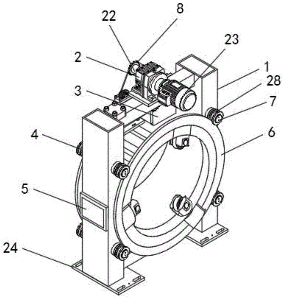
图1为本发明整体结构示意图;Fig. 1 is the overall structure schematic diagram of the present invention;
图2为本发明主视图;Fig. 2 is the front view of the present invention;
图3为本发明侧视图;Figure 3 is a side view of the present invention;
图4为本发明防护架结构示意图;Fig. 4 is the structural schematic diagram of the protective frame of the present invention;
图5为本发明边环结构示意图;Fig. 5 is the structural representation of the side ring of the present invention;
图6为本发明定位架结构示意图;Fig. 6 is the structural schematic diagram of the positioning frame of the present invention;
图7为本发明张力轮结构示意图;Fig. 7 is the schematic diagram of the structure of the tension wheel of the present invention;
图中:1、支架;2、顶架;3、液压泵;4、传送轮;5、电源;6、防护架;7、辅助轮;8、驱动轮;9、张力轮;10、传送链;11、液压伸缩顶杆;12、边环;13、固定座;14、螺钉;15、气泵;16、定位架;17、收纳槽;18、第一气动伸缩杆;19、轮座;20、转轴;21、滑轮;22、传动轴;23、驱动电机;24、支脚;25、侧板;26、滑槽;27、第二气动伸缩杆;28、环形槽。In the picture: 1. Bracket; 2. Top frame; 3. Hydraulic pump; 4. Transmission wheel; 5. Power supply; 6. Protective frame; 7. Auxiliary wheel; 8. Driving wheel; 9. Tension wheel; 10. Transmission chain ;11. Hydraulic telescopic ejector rod; 12. Side ring; 13. Fixed seat; 14. Screws; 15. Air pump; 16. Positioning frame; 17. Storage slot; 21, pulley; 22, transmission shaft; 23, drive motor; 24, foot; 25, side plate; 26, chute; 27, second pneumatic telescopic rod; 28, annular groove.
具体实施方式Detailed ways
下面将结合实施例对本发明的技术方案进行清楚、完整地描述,显然,所描述的实施例仅仅是本发明一部分实施例,而不是全部的实施例。基于本发明中的实施例,本领域普通技术人员在没有作出创造性劳动前提下所获得的所有其它实施例,都属于本发明保护的范围。The technical solutions of the present invention will be clearly and completely described below with reference to the embodiments. Obviously, the described embodiments are only a part of the embodiments of the present invention, rather than all the embodiments. Based on the embodiments of the present invention, all other embodiments obtained by those of ordinary skill in the art without creative efforts shall fall within the protection scope of the present invention.
请参阅图1-7所示,一种核磁共振超导磁体用安置防护设备,包括支架1以及安装在内部的防护架6,支架1侧壁上安装有电源5,且支架1底部设置有两个支脚24,支架1顶部固定安装有顶架2,顶架2侧壁上安装有驱动电机23,驱动电机23侧壁上连接有一根贯穿支架1的传动轴22,传动轴22一端连接有驱动轮8,支架1顶部内壁上安装有液压泵3,液压泵3侧壁上连接有两根液压伸缩顶杆11,支架1一侧外壁上安装有四个传送轮4,且支架1另一侧外壁上安装有四个与传送轮4位置相对应的辅助轮7,传送轮4与辅助轮7上均设置有环形槽28,防护架6安装在四个传送轮4与四个辅助轮7之间,安装传送轮4的支架1顶部侧壁上固定安装有两个侧板25,两个侧板25上均设置有一个滑槽26,滑槽26内部安装有可左右调整位置的张力轮9,驱动轮8与两个张力轮9、四个传送轮4之间缠绕有一根传送链10;Please refer to FIG. 1-7 , a protective equipment for NMR superconducting magnet placement, including a
防护架6两端侧壁上均安装有一个边环12,边环12上设置有两个固定座13,两个固定座13上均安装有一个用于将边环12与防护架6之间固定连接的螺钉14,边环12上安装有三个均匀分布的气泵15,且边环12内壁上安装有三个与气泵15位置相对应的定位架16,定位架16与气泵15之间通过两根第二气动伸缩杆27相连接,定位架16与气泵15之间设置有收纳槽17,收纳槽17内部安装有一个轮座19,轮座19底部连接有一根与气泵15相连接的第一气动伸缩杆18,轮座19内部安装有滑轮21,滑轮21两侧通过转轴20与轮座19相连接。A
防护架6两端的环形结构分别安装在四个传送轮4的环形槽28、四个辅助轮7的环形槽28内部,使得防护架6能够在四个传送轮4的环形槽28、四个辅助轮7之间转动。The annular structures at both ends of the
防护架6通过四个传送轮4、四个辅助轮7与支架1内壁之间转动连接,传送轮4通过传送链10与驱动轮8之间传动连接,使得核磁共振超导磁体在需要大幅度调整角度时,利用驱动电机23驱动传动轴22转动,从而带动驱动轮8转动,驱动轮8利用传送链10带动四个传送轮4转动,从而带动防护架6一同转动,防护架6在转动的过程中辅助轮7辅助其转动,从而完成对核磁共振超导磁体角度的大幅度调整。The
液压伸缩顶杆11在初始时抵在防护架6侧壁上,防护架6在转动时液压伸缩顶杆11收缩,当完成防护架6的角度调整后,能够利用气泵15来驱动两根第二气动伸缩杆27复位,即可防止防护架6完成调整后角度出现偏移。The hydraulic telescopic
定位架16通过两根第二气动伸缩杆27与边环12内壁之间活动连接。The
轮座19通过第一气动伸缩杆18与收纳槽17内壁之间活动连接,轮座19在初始时完全收纳在收纳槽17内部,从而使得安装后的核磁共振超导磁体需要根据实际情况以及实际需求调整角度时,能够通过外接的PLC控制器控制气泵15驱动第一气动伸缩杆18、第二气动伸缩杆27伸缩,先控制第一气动伸缩杆18伸长来带动轮座19从收纳槽17内部顶出并接入核磁共振超导磁体的两端的环槽内部,再控制第二气动伸缩杆27收缩来带动定位架16不再固定核磁共振超导磁体的位置,此时整个核磁共振超导磁体能够在防护架6内部依靠六个滑轮21的转动而转动,此种调整方式适用于对核磁共振超导磁体进行小幅度的位置、角度调整,当调整完成后利用PLC控制器先控制气泵15来驱动两根第二气动伸缩杆27复位,再利用PLC控制器控制气泵15来驱动第一气动伸缩杆18复位,即可重新固定核磁共振超导磁体,此种方式既能够保证核磁共振超导磁体的安全性能,而且又方便对核磁共振超导磁体进行精准的调整。The
三个定位架16围成环形结构,且定位架16顶部为弧形结构。The three
该种安置防护设备的使用方法,具体步骤为:The use method of this kind of placement protective equipment, the specific steps are:
步骤一:先将需要防护的核磁共振超导磁体安装在防护架6内部,在安装时轮座19内部的滑轮21正对着核磁共振超导磁体两端开设的环槽,随后利用外接的PLC控制器驱动所有的气泵15均启动,利用气泵15先驱动第二气动伸缩杆27伸长,利用第二气动伸缩杆27的伸长来带动定位架16调整位置,使核磁共振超导磁体被六个定位架16夹固在防护架6内部,利用防护架6来对核磁共振超导磁体进行安置以及保护;Step 1: First, install the NMR superconducting magnet to be protected inside the
步骤二:安装后的核磁共振超导磁体需要根据实际情况以及实际需求调整角度时,通过气泵15驱动第一气动伸缩杆18、第二气动伸缩杆27伸缩,先控制第一气动伸缩杆18伸长来带动轮座19从收纳槽17内部顶出并接入核磁共振超导磁体的两端的环槽内部,再控制第二气动伸缩杆27收缩来带动定位架16不再固定核磁共振超导磁体的位置,此时整个核磁共振超导磁体在防护架6内部依靠六个滑轮21的转动而转动,当调整完角度后,控制气泵15来驱动两根第二气动伸缩杆27复位,再利用PLC控制器控制气泵15来驱动第一气动伸缩杆18复位,即可重新固定核磁共振超导磁体;Step 2: When the installed nuclear magnetic resonance superconducting magnet needs to adjust the angle according to the actual situation and actual demand, the first pneumatic
步骤三:核磁共振超导磁体在需要大幅度调整角度时,先通过PLC控制器控制液压泵3启动,利用液压泵3驱动两根液压伸缩顶杆11收缩,使液压伸缩顶杆11不再抵着防护架6,此时再通过PLC控制器控制驱动电机23启动,利用驱动电机23驱动传动轴22转动,从而带动驱动轮8转动,驱动轮8利用传送链10带动四个传送轮4转动,从而带动防护架6一同转动,防护架6在转动的过程中辅助轮7辅助其转动,从而完成对核磁共振超导磁体角度的大幅度调整,当完成调整后利用液压泵3驱动液压伸缩顶杆11复位,使得防护架6位置固定。Step 3: When the angle of the nuclear magnetic resonance superconducting magnet needs to be greatly adjusted, the PLC controller controls the
本发明的有益效果为:由于每个定位架16内部均安装有一个与第一气动伸缩杆18相连接的轮座19,轮座19内部安装有滑轮21,并且轮座19在初始时收纳进入收纳槽17内部,从而使得安装后的核磁共振超导磁体需要根据实际情况以及实际需求调整角度时,能够通过外接的PLC控制器控制气泵15驱动第一气动伸缩杆18、第二气动伸缩杆27伸缩,先控制第一气动伸缩杆18伸长来带动轮座19从收纳槽17内部顶出并接入核磁共振超导磁体的两端的环槽内部,再控制第二气动伸缩杆27收缩来带动定位架16不再固定核磁共振超导磁体的位置,此时整个核磁共振超导磁体能够在防护架6内部依靠六个滑轮21的转动而转动,此种调整方式适用于对核磁共振超导磁体进行小幅度的位置、角度调整,当调整完成后利用PLC控制器先控制气泵15来驱动两根第二气动伸缩杆27复位,再利用PLC控制器控制气泵15来驱动第一气动伸缩杆18复位,即可重新固定核磁共振超导磁体,此种方式既能够保证核磁共振超导磁体的安全性能,而且又方便对核磁共振超导磁体进行精准的调整;The beneficial effects of the present invention are: since each
由于驱动电机23以及四个传送轮4、四个辅助轮7的存在,使得核磁共振超导磁体在需要大幅度调整角度时,先通过PLC控制器控制液压泵3启动,利用液压泵3驱动两根液压伸缩顶杆11收缩,从而使得液压伸缩顶杆11不再抵着防护架6,使得防护架6可以转动,此时再通过PLC控制器控制驱动电机23启动,利用驱动电机23驱动传动轴22转动,从而带动驱动轮8转动,驱动轮8利用传送链10带动四个传送轮4转动,从而带动防护架6一同转动,防护架6在转动的过程中辅助轮7辅助其转动,从而完成对核磁共振超导磁体角度的大幅度调整,当完成调整后利用液压泵3驱动液压伸缩顶杆11复位,使得防护架6位置固定,此种方式适用于对核磁共振超导磁体进行大幅度的角度调整,更加方便。Due to the existence of the
本发明在使用时,首先,对整个装置进行组装,将顶架2固定在支架1顶部,并且顶架2上固定安装驱动电机23,驱动电机23的传动轴22与驱动轮8相连接,随后,在支架1一侧外壁上安装四个均匀分布的传送轮4,在支架1另一侧外壁上安装四个均匀分布的辅助轮7,且辅助轮7的位置与传送轮4相对应,随后,在四个传送轮4与四个辅助轮7之间安装防护架6,并且防护架6两端的环形结构分别安装在传送轮4的环形槽28、辅助轮7的环形槽28内部,紧接着,在支架1安装传送轮4的侧壁上安装两块位于驱动轮8、传送轮4之间的侧板25,两块侧板25上的滑槽26内部均安装一个张力轮9,随后,将驱动轮8与两个张力轮9、四个传送轮4之间通过传送链10相连接,并且在防护架6两端均安装一个边环12,边环12与防护架6之间通过固定座13以及螺钉14固定,并且将驱动电机23、液压泵3、气泵15均与外部的PLC控制器(型号为:CPM1A)相连接,完成组装后即可投入使用。在使用前先将需要防护的核磁共振超导磁体安装在防护架6内部,在安装时轮座19内部的滑轮21正对着核磁共振超导磁体两端开设的环槽,随后利用PLC控制器驱动所有的气泵15均启动,利用气泵15先驱动第二气动伸缩杆27伸长,利用第二气动伸缩杆27的伸长来带动定位架16调整位置,从而使得核磁共振超导磁体被六个定位架16夹固在防护架6内部,利用防护架6来对核磁共振超导磁体进行安置以及保护,由于每个定位架16内部均安装有一个与第一气动伸缩杆18相连接的轮座19,轮座19内部安装有滑轮21,并且轮座19在初始时收纳进入收纳槽17内部,从而使得安装后的核磁共振超导磁体需要根据实际情况以及实际需求调整角度时,通过PLC控制器控制气泵15驱动第一气动伸缩杆18、第二气动伸缩杆27伸缩,先控制第一气动伸缩杆18伸长来带动轮座19从收纳槽17内部顶出并接入核磁共振超导磁体的两端的环槽内部,再控制第二气动伸缩杆27收缩来带动定位架16不再固定核磁共振超导磁体的位置,此时整个核磁共振超导磁体能够在防护架6内部依靠六个滑轮21的转动而转动,此种调整方式适用于对核磁共振超导磁体进行小幅度的位置、角度调整,当调整完成后利用PLC控制器先控制气泵15来驱动两根第二气动伸缩杆27复位,再利用PLC控制器控制气泵15来驱动第一气动伸缩杆18复位,即可重新固定核磁共振超导磁体,此种方式既能够保证核磁共振超导磁体的安全性能,而且又方便对核磁共振超导磁体进行精准的调整;由于驱动电机23以及四个传送轮4、四个辅助轮7的存在,使得核磁共振超导磁体在需要大幅度调整角度时,先通过PLC控制器控制液压泵3启动,利用液压泵3驱动两根液压伸缩顶杆11收缩,从而使得液压伸缩顶杆11不再抵着防护架6,使得防护架6可以转动,此时再通过PLC控制器控制驱动电机23启动,利用驱动电机23驱动传动轴22转动,从而带动驱动轮8转动,驱动轮8利用传送链10带动四个传送轮4转动,从而带动防护架6一同转动,防护架6在转动的过程中辅助轮7辅助其转动,从而完成对核磁共振超导磁体角度的大幅度调整,当完成调整后利用液压泵3驱动液压伸缩顶杆11复位,使得防护架6位置固定,此种方式适用于对核磁共振超导磁体进行大幅度的角度调整,更加方便。When the present invention is used, firstly, the whole device is assembled, the
以上公开的本发明优选实施例只是用于帮助阐述本发明。优选实施例并没有详尽叙述所有的细节,也不限制该发明仅为的具体实施方式。显然,根据本说明书的内容,可作很多的修改和变化。本说明书选取并具体描述这些实施例,是为了更好地解释本发明的原理和实际应用,从而使所属技术领域技术人员能很好地理解和利用本发明。本发明仅受权利要求书及其全部范围和等效物的限制。The above-disclosed preferred embodiments of the present invention are provided only to help illustrate the present invention. The preferred embodiments do not describe all the details and do not limit the invention to specific embodiments only. Obviously, many modifications and variations are possible in light of the content of this specification. These embodiments are selected and described in this specification in order to better explain the principles and practical applications of the present invention, so that those skilled in the art can well understand and utilize the present invention. The present invention is to be limited only by the claims and their full scope and equivalents.
Claims (8)
Priority Applications (1)
| Application Number | Priority Date | Filing Date | Title |
|---|---|---|---|
| CN201910605433.2A CN110517841B (en) | 2019-07-05 | 2019-07-05 | A kind of placement protection equipment for nuclear magnetic resonance superconducting magnet |
Applications Claiming Priority (1)
| Application Number | Priority Date | Filing Date | Title |
|---|---|---|---|
| CN201910605433.2A CN110517841B (en) | 2019-07-05 | 2019-07-05 | A kind of placement protection equipment for nuclear magnetic resonance superconducting magnet |
Publications (2)
| Publication Number | Publication Date |
|---|---|
| CN110517841A CN110517841A (en) | 2019-11-29 |
| CN110517841B true CN110517841B (en) | 2020-12-22 |
Family
ID=68623500
Family Applications (1)
| Application Number | Title | Priority Date | Filing Date |
|---|---|---|---|
| CN201910605433.2A Active CN110517841B (en) | 2019-07-05 | 2019-07-05 | A kind of placement protection equipment for nuclear magnetic resonance superconducting magnet |
Country Status (1)
| Country | Link |
|---|---|
| CN (1) | CN110517841B (en) |
Citations (2)
| Publication number | Priority date | Publication date | Assignee | Title |
|---|---|---|---|---|
| CN102870174A (en) * | 2010-03-30 | 2013-01-09 | 日本超导体技术公司 | Superconducting magnet device |
| CN206194474U (en) * | 2016-12-05 | 2017-05-24 | 潍坊新力超导磁电科技有限公司 | A structure for protecting magnetic resonance superconducting magnet coil |
Family Cites Families (4)
| Publication number | Priority date | Publication date | Assignee | Title |
|---|---|---|---|---|
| CN100434038C (en) * | 2004-03-05 | 2008-11-19 | 西门子(中国)有限公司 | Adjusting device for magnetic field of magnetic resonance imaging equipment |
| US7646272B1 (en) * | 2007-10-12 | 2010-01-12 | The United States Of America As Represented By The United States Department Of Energy | Freely oriented portable superconducting magnet |
| CN103511811B (en) * | 2013-07-18 | 2015-04-15 | 华中科技大学 | Supporting device of annular superconducting magnet |
| DE102017205485A1 (en) * | 2017-03-31 | 2018-10-04 | Bruker Biospin Gmbh | Permanent magnet arrangement for MR apparatus with axially and laterally displaceable, rotatably mounted ring assemblies |
-
2019
- 2019-07-05 CN CN201910605433.2A patent/CN110517841B/en active Active
Patent Citations (2)
| Publication number | Priority date | Publication date | Assignee | Title |
|---|---|---|---|---|
| CN102870174A (en) * | 2010-03-30 | 2013-01-09 | 日本超导体技术公司 | Superconducting magnet device |
| CN206194474U (en) * | 2016-12-05 | 2017-05-24 | 潍坊新力超导磁电科技有限公司 | A structure for protecting magnetic resonance superconducting magnet coil |
Also Published As
| Publication number | Publication date |
|---|---|
| CN110517841A (en) | 2019-11-29 |
Similar Documents
| Publication | Publication Date | Title |
|---|---|---|
| CN110739818A (en) | A fully automatic coil winding method for motor rotor | |
| CN110517841B (en) | A kind of placement protection equipment for nuclear magnetic resonance superconducting magnet | |
| CN207671465U (en) | A kind of take-up and pay-off device for large-scale power transformer commissioning test | |
| CN115947177A (en) | A winding device for cable production | |
| CN207957382U (en) | A kind of building is electromechanical to use cable coiling device | |
| CN111377307B (en) | AB shaft retracting and releasing clamping head of printing machine | |
| CN107369877B (en) | Vehicle-mounted antenna control system | |
| CN219659283U (en) | A mobile device for electric power operation construction | |
| CN106252107B (en) | A kind of capacitor push device for processing | |
| CN117854923A (en) | Speed-adjustable transformer winder and winding method thereof | |
| CN212018963U (en) | A multi-specification wire rope drawing equipment | |
| CN220453160U (en) | Supporting structure for large-scale environmental protection equipment | |
| CN223142311U (en) | A bracket for installing network equipment in a cabinet | |
| CN118539693B (en) | Automatic wire insertion machine for coil assembly and automatic wire insertion process | |
| CN223804629U (en) | A winding device for cable production | |
| CN222154683U (en) | Stator machining positioning device | |
| CN220033479U (en) | Magic subsides unreeling device for cutting machine is pasted to magic | |
| CN221886237U (en) | Adjustable saddle of horizontal plastic machine | |
| CN217268770U (en) | Transformer substation steel structure construction protection device | |
| CN223123674U (en) | A mold for cable manufacturing that is easy to clean | |
| CN213988421U (en) | Cable forming device for cable production | |
| CN223372479U (en) | Crane steel cable processing winding device | |
| CN220011676U (en) | Cable winding and unwinding device for communication engineering | |
| CN105731134A (en) | Film reeling machine | |
| CN220243025U (en) | New energy automobile fills electric pile mounting structure |
Legal Events
| Date | Code | Title | Description |
|---|---|---|---|
| PB01 | Publication | ||
| PB01 | Publication | ||
| SE01 | Entry into force of request for substantive examination | ||
| SE01 | Entry into force of request for substantive examination | ||
| GR01 | Patent grant | ||
| GR01 | Patent grant | ||
| TR01 | Transfer of patent right |
Effective date of registration: 20211130 Address after: 213000 No. 17, Qianjia Road, Yaoguan Town, Changzhou Economic Development Zone, Jiangsu Province Patentee after: Lingyue Electromechanical Technology (Changzhou) Co.,Ltd. Address before: 467000 Henan province Pingdingshan city new city Longxiang Road Patentee before: Henan University of Urban Construction |
|
| TR01 | Transfer of patent right |