CN110480949B - Engine exhaust pipe core-pulling mechanism - Google Patents
Engine exhaust pipe core-pulling mechanism Download PDFInfo
- Publication number
- CN110480949B CN110480949B CN201910865980.4A CN201910865980A CN110480949B CN 110480949 B CN110480949 B CN 110480949B CN 201910865980 A CN201910865980 A CN 201910865980A CN 110480949 B CN110480949 B CN 110480949B
- Authority
- CN
- China
- Prior art keywords
- product
- guide
- mold core
- block
- open slot
- Prior art date
- Legal status (The legal status is an assumption and is not a legal conclusion. Google has not performed a legal analysis and makes no representation as to the accuracy of the status listed.)
- Active
Links
Images


Classifications
-
- B—PERFORMING OPERATIONS; TRANSPORTING
- B29—WORKING OF PLASTICS; WORKING OF SUBSTANCES IN A PLASTIC STATE IN GENERAL
- B29C—SHAPING OR JOINING OF PLASTICS; SHAPING OF MATERIAL IN A PLASTIC STATE, NOT OTHERWISE PROVIDED FOR; AFTER-TREATMENT OF THE SHAPED PRODUCTS, e.g. REPAIRING
- B29C45/00—Injection moulding, i.e. forcing the required volume of moulding material through a nozzle into a closed mould; Apparatus therefor
- B29C45/17—Component parts, details or accessories; Auxiliary operations
- B29C45/26—Moulds
- B29C45/261—Moulds having tubular mould cavities
- B29C45/2614—Moulds having tubular mould cavities for manufacturing bent tubular articles using an undercut forming mould core
-
- B—PERFORMING OPERATIONS; TRANSPORTING
- B29—WORKING OF PLASTICS; WORKING OF SUBSTANCES IN A PLASTIC STATE IN GENERAL
- B29C—SHAPING OR JOINING OF PLASTICS; SHAPING OF MATERIAL IN A PLASTIC STATE, NOT OTHERWISE PROVIDED FOR; AFTER-TREATMENT OF THE SHAPED PRODUCTS, e.g. REPAIRING
- B29C45/00—Injection moulding, i.e. forcing the required volume of moulding material through a nozzle into a closed mould; Apparatus therefor
- B29C45/17—Component parts, details or accessories; Auxiliary operations
- B29C45/26—Moulds
- B29C45/33—Moulds having transversely, e.g. radially, movable mould parts
-
- B—PERFORMING OPERATIONS; TRANSPORTING
- B29—WORKING OF PLASTICS; WORKING OF SUBSTANCES IN A PLASTIC STATE IN GENERAL
- B29C—SHAPING OR JOINING OF PLASTICS; SHAPING OF MATERIAL IN A PLASTIC STATE, NOT OTHERWISE PROVIDED FOR; AFTER-TREATMENT OF THE SHAPED PRODUCTS, e.g. REPAIRING
- B29C45/00—Injection moulding, i.e. forcing the required volume of moulding material through a nozzle into a closed mould; Apparatus therefor
- B29C45/17—Component parts, details or accessories; Auxiliary operations
- B29C45/40—Removing or ejecting moulded articles
- B29C45/4005—Ejector constructions; Ejector operating mechanisms
-
- B—PERFORMING OPERATIONS; TRANSPORTING
- B29—WORKING OF PLASTICS; WORKING OF SUBSTANCES IN A PLASTIC STATE IN GENERAL
- B29C—SHAPING OR JOINING OF PLASTICS; SHAPING OF MATERIAL IN A PLASTIC STATE, NOT OTHERWISE PROVIDED FOR; AFTER-TREATMENT OF THE SHAPED PRODUCTS, e.g. REPAIRING
- B29C45/00—Injection moulding, i.e. forcing the required volume of moulding material through a nozzle into a closed mould; Apparatus therefor
- B29C45/17—Component parts, details or accessories; Auxiliary operations
- B29C45/40—Removing or ejecting moulded articles
- B29C45/44—Removing or ejecting moulded articles for undercut articles
- B29C45/4407—Removing or ejecting moulded articles for undercut articles by flexible movement of undercut portions of the articles
-
- B—PERFORMING OPERATIONS; TRANSPORTING
- B29—WORKING OF PLASTICS; WORKING OF SUBSTANCES IN A PLASTIC STATE IN GENERAL
- B29C—SHAPING OR JOINING OF PLASTICS; SHAPING OF MATERIAL IN A PLASTIC STATE, NOT OTHERWISE PROVIDED FOR; AFTER-TREATMENT OF THE SHAPED PRODUCTS, e.g. REPAIRING
- B29C45/00—Injection moulding, i.e. forcing the required volume of moulding material through a nozzle into a closed mould; Apparatus therefor
- B29C45/17—Component parts, details or accessories; Auxiliary operations
- B29C45/26—Moulds
- B29C45/33—Moulds having transversely, e.g. radially, movable mould parts
- B29C2045/338—Mould parts with combined axial and transversal movements
Landscapes
- Engineering & Computer Science (AREA)
- Manufacturing & Machinery (AREA)
- Mechanical Engineering (AREA)
- Moulds For Moulding Plastics Or The Like (AREA)
Abstract
The invention discloses a core-pulling mechanism of an engine exhaust pipe, which comprises an upper template, a lower template, mold feet, a product, an ejector plate and a mold core for molding the product, the upper template is positioned on the upper surface of the lower template, the lower template is positioned between the upper template and the mold feet, the ejector pin plate is in up-down sliding fit between the die legs and the lower template, the die core comprises a first die core used for forming the lower end of a product and a second die core used for forming the upper end of the product, the first mold core is used for linearly pulling cores corresponding to a small part of a product, the second mold core is used for circularly pulling cores corresponding to a large part of the product, the upper surface of the lower template is provided with a first open slot along the width direction of the lower template, the upper surface of the lower template is provided with a second open slot along the length direction of the lower template, one end of the second open slot is communicated with the first open slot, and the invention provides the engine exhaust pipe core pulling mechanism which is convenient to core and easy to core.
Description
Technical Field
The invention relates to the field of molds, in particular to a core-pulling mechanism for an engine exhaust pipe.
Background
Along with the development of science and technology, the car becomes the general instrument of riding instead of walk of people gradually, and the engine blast pipe is one of the component parts of car, and the material of engine blast pipe is the flexible glue, and the engine blast pipe passes through the mould shaping. The engine exhaust pipe passageway is arc-shaped, and the mechanism of loosing core needs to be utilized to loose core to engine exhaust pipe during shaping, according to prior art, utilizes ordinary circular arc to loose core the mechanism and looses core to engine exhaust pipe, and it is inconvenient to loose core, looses core the difficulty.
Disclosure of Invention
The technical problem to be solved by the invention is as follows: the engine exhaust pipe core pulling mechanism overcomes the defects of the prior art and is convenient to core and easy to core.
The technical scheme adopted by the invention is as follows: the engine exhaust pipe core pulling mechanism comprises an upper template, a lower template, mold feet, a product, an ejector plate and a mold core for forming the product, wherein the upper template is positioned on the upper surface of the lower template, the lower template is positioned between the upper template and the mold feet, the ejector plate is in up-and-down sliding fit between the mold feet and the lower template, the mold core comprises a first mold core used in the lower end of the formed product and a second mold core used in the upper end of the formed product, the first mold core is used for linearly pulling cores corresponding to small parts of the product, the second mold core is used for pulling cores corresponding to most circular arcs of the product, the upper surface of the lower template is provided with a first open slot along the width direction of the lower template, the upper surface of the lower template is provided with a second open slot along the length direction of the lower template, one end of the second open slot is communicated with the first open slot, the first mold core is positioned in the first, the middle of the second mold core is positioned in a second open slot, the upper end of the second mold core is positioned on the upper surface of a lower template, the lower end of the second mold core extends into the first open slot and contacts with the upper end of the first mold core, the first open slot is internally provided with a first sliding block set used for forming the outer surface of the lower end of a product and a second sliding block set used for forming the outer surface of the upper end of the product respectively, an ejection mechanism used for ejecting the product is arranged between an ejector plate and the lower template, and the second mold core can rotate up and down around the upper end of the second mold core and can move dynamically on the upper end of the second mold core.
After adopting the structure, compared with the prior art, the invention has the following advantages: the product is a 90-degree elbow pipe, the mold cores are divided into a first mold core and a second mold core, the mold cores are all used for forming an internal pipeline of the product, the first mold core is used for forming a straight pipe part at the end part of the lower end of the product, the second mold core is used for forming other parts of the product and comprises an arc pipeline part, a first slide block group is used for forming the outer surface of the lower end of the product and also used for holding the product, the first slide block group corresponds to the first mold core, the inner surface of the part formed by the first mold core is used for forming the outer surface of the part, a second slide block group is used for forming the outer surface of other parts of the product, when the mold is opened, the second slide block group is driven by an inclined guide post to be demolded, then the second mold core can be vertically rotated around the upper end of the second mold core by utilizing the middle of the second mold core, and the upper end of the second, the middle of the second mold core is forced to rotate around the rotating pin to do angle swing motion, along with the change of the middle ejection distance of the second mold core, the position of the fulcrum at the upper end of the second mold core is changed, the mechanism realizes the compound motion of linear motion and rotating motion, the material of the mold product is soft glue, the lever demolding mechanism is adopted to directly and forcibly demolish the product, the simple mechanism is used for replacing a complex arc core pulling mechanism, the mold cost is reduced, the subsequent mold is simple and convenient to produce, maintain and pull core by utilizing the lever principle, the core pulling is convenient, and the core pulling is easy.
Preferably, the upper surface of the lower template is provided with a tailstock, the side surface of the tailstock is provided with a fixed pin, the second open slot is positioned between the first open slot and the tailstock, the two side surfaces of the upper end of the second mold core are respectively provided with a first guide slot, the fixed pin can be respectively matched in the first guide slots in a sliding manner, the upper surface of the ejector plate is provided with a top plate, the top plate is provided with a push rod, the lower surface of the second mold core positioned at the part of the second open slot is provided with an open slot with a downward opening, the open slot is internally provided with a rotating pin parallel to the fixed pin, the upper end of the push rod passes through the lower template to be matched on the rotating pin in a rotating manner, the push rod pushes the middle of the second mold core to be forced by the fixed pin, the middle of the second mold core is forced to rotate around the rotating pin to perform angular swinging movement, and the relative position of the, the fulcrum of the lever mechanism is in dynamic motion, the combination of the first guide groove and the fixing pin is the mechanism to realize the compound motion of linear motion and rotary motion, in addition, the upper end of the first guide groove is provided with a vertical groove, the middle of the second mold core is in linear motion, so that the space is vacated, and the middle of the second mold core is ensured not to interfere with the side surface of the second open groove.
Preferably, the open slot penetrates through the side face, far away from the first open slot, of the second mold core, so that the second mold core can swing at a large angle, and a product can be taken out conveniently.
Preferably, the axis of the first guide groove forms an included angle with the horizontal plane, and the height of one end, away from the tailstock, of the first guide groove is gradually increased to the height of one end, close to the tailstock, of the first guide groove, so that the core pulling at the lower end of the second mold core is facilitated.
Preferably, the bottom of the second open slot and the lower surface of the lower template are respectively provided with a first guide block, the push rod penetrates through the first guide blocks respectively, the first guide blocks guide the push rod, and the reliability is high.
Preferably, the upper surface of the first mold core is respectively provided with a convex block and a clamping block which are used for forming the outer side of the arc at the lower end of the product, the side surface of the convex block close to the second open slot is an inclined plane, the clamping block is perpendicular to the upper surface of the first mold core, one part of the clamping block is arranged on the inclined plane, the first mold core is convenient to pull the product, the second mold core is convenient to separate from the product, the lower surface of the second mold core is provided with a clamping groove, the upper end of the clamping block is clamped in the clamping groove, the second mold core and the first mold core are connected, the injection molding reliability is.
Preferably, the ejection mechanism is that a fixed block is arranged at the bottom of the first open slot, the lower end of the first mold core is fixed on the fixed block, the upper surface of the fixed block is provided with at least two grooves, the grooves are internally provided with straight jacking blocks, the straight jacking blocks can be matched in the grooves in a vertical sliding way, the straight ejector blocks correspond to the grooves one by one, the grooves are distributed along the outer circumference of the first mold core, ejector rods are arranged on the ejector plate, the upper end of the ejector rod penetrates through the lower template and is propped against the lower surface of the straight ejector block, the ejector rods correspond to the straight ejector blocks one by one, the straight ejection block is ejected on the outer circumference of the lower surface of the lower end of the product, the ejection rod is used for pushing the straight ejection block, the straight ejection blocks are ejected out of the product by the straight ejection blocks, the structure is simple, the number of the straight ejection blocks is four, and the straight ejection blocks are uniformly distributed along the outer circumference of the lower surface of the product.
Preferably, the first sliding block group comprises a first sliding block used for forming one half of the outer surface of the lower end of a product and a second sliding block used for forming the other half of the outer surface of the lower end of the product, the first sliding block and the second sliding block are respectively matched in the first open slot in a front-back sliding mode, the first sliding block and the second sliding block are respectively located on the front side and the back side of the product, one end, close to the product, of the first sliding block and one end, close to the product, of the second sliding block are respectively located on the fixed blocks, and the structure is simple.
Preferably, the inner walls of the left side and the right side of the first open slot are respectively provided with a guide seat along the axial direction of the first open slot, the side surfaces of the lower end of the guide seat are respectively provided with a second guide slot, a second guide block is arranged in the second guide slot on the right side of the guide seat in a sliding fit manner, one end of the second guide block close to a product is respectively fixed on the lower surface of the first slider and the lower surface of the second slider, the side surface of the upper end of the guide seat on the right side of the product is provided with a third guide slot, the third guide slot is communicated with the second guide slot, the mold foot is provided with a through hole, a rack is arranged in the through hole, the upper end of the rack sequentially penetrates through the ejector plate and the lower template in the third guide slot in a sliding fit manner, the side surface of the rack close to the second guide block is sequentially provided with a first vertical slot, a first oblique chute, a second oblique chute and a second vertical slot from top to bottom, the side surface of the second guide block close to the rack is sequentially provided with a third inclined chute, a fourth inclined chute and a fifth inclined chute from the direction far away from the product to the direction close to the product, the side wall of the third inclined chute is provided with a first vertical guide surface convenient for the first vertical chute to pass through, the side wall of the fifth inclined chute is provided with a second vertical guide surface convenient for the second vertical chute to pass through, the rack is in sliding fit with the second guide block to realize that the second guide block is in sliding fit in the second guide groove, a guide seat is arranged to facilitate the core pulling of the second sliding block set, the rack is arranged, the size of the rack positioned on the ejector pin plate is larger than that of the rack positioned on the ejector plate, the rack can drive the ejector plate to move firstly, the core pulling of the second mold core is realized firstly, then the ejection of the product is realized, a limiting mechanism is arranged between the ejector pin plate and the ejector plate, the limiting mechanism comprises a, the lower end of the limiting sleeve is fixed on the lower surface of the ejector plate, the upper end of the limiting sleeve penetrates through the ejector plate to be in contact with the lower surface of the limiting block, the diameter of the lower end of the limiting screw is larger than that of the upper end of the limiting screw, the lower end of the limiting screw can be in sliding fit in the limiting sleeve, the upper end of the limiting screw penetrates through the upper end of the limiting sleeve to be fixed in the limiting block, when the top plate moves upwards, the top plate drives the lower end of the limiting screw to be in sliding fit in the limiting sleeve, the limiting screw can drive the limiting sleeve and the ejector plate to move together when the lower end of the limiting screw moves to the top of the limiting sleeve, product core pulling and product ejection are realized at one time, the structure is simple, when the rack moves upwards, the rack is in sliding fit in the third guide groove, meanwhile, the first vertical groove of the rack slides to be in up and down sliding fit with the, the rack continues up to push up, drive the second guide block toward the direction motion of keeping away from the product, first slider realizes loosing core with the second slider, the rack continues up to push up, oblique spout of second and fifth spout sliding fit, continue to drive the second guide block toward the direction motion of keeping away from the product, first slider and second slider realize loosing core completely, be similar to the cooperation of rack and rack, because oblique spout of second and the vertical groove intercommunication of second, the vertical groove of second and the vertical guide surface of the second of fifth spout sliding fit from top to bottom, do not hinder ejecting of product, first slider left side and second slider left side sliding fit respectively are being located the left second guide way of guide holder.
Preferably, the second slider group comprises a third slider used for forming half of the outer surface of the upper end of the product and a fourth slider used for forming the other half of the outer surface of the upper end of the product, the third slider and the fourth slider are respectively in front-back sliding fit in the first open slot, the third slider and the fourth slider are respectively positioned at the front side and the rear side of the product, the middle part of the third slider is positioned on the first slider, the two sides of the third slider are respectively positioned on the upper surface of the guide seat, the middle part of the fourth slider is positioned on the second slider, the two sides of the fourth slider are respectively positioned on the upper surface of the guide seat, the two sides of the third slider are respectively provided with a first inclined guide pillar, the lower end of the first inclined guide pillar is positioned in the guide seat, the upper end of the first inclined guide pillar is fixed on the lower surface of the upper die plate, and the two sides of the fourth slider are respectively provided with, the lower end of the second inclined guide post is located in the guide seat, the upper end of the second inclined guide post is fixed to the lower surface of the upper template, the structure is simple, the core pulling of the second sliding block set is achieved by opening the upper template and the lower template, namely the core pulling of the common inclined guide post is achieved, and the structure is simple.
Drawings
FIG. 1 is a perspective view of an engine exhaust pipe core pulling mechanism of the present invention;
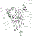
FIG. 2 is a perspective view of the engine exhaust pipe core pulling mechanism of the present invention with the upper die plate removed;
FIG. 3 is a perspective view of the engine exhaust pipe core pulling mechanism of the present invention with the upper die plate, the lower die plate, the die legs, the ejector plate and the top plate removed;
FIG. 4 is a perspective view of a first mold core and a second mold core of the engine exhaust pipe core pulling mechanism of the present invention;
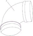
FIG. 5 is a perspective view of an engine exhaust pipe core pulling mechanism product of the present invention;
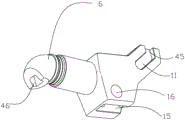
FIG. 6 is a perspective view of a second mold core of the engine exhaust pipe core pulling mechanism of the present invention;
FIG. 7 is a perspective view of the ejector mechanism of the engine exhaust pipe core pulling mechanism of the present invention;
FIG. 8 is a perspective view of the guide block, rack and second guide block of the engine exhaust pipe core pulling mechanism of the present invention;
FIG. 9 is a perspective view of the engine exhaust pipe core pulling mechanism rack of the present invention;
FIG. 10 is a perspective view of a second guide block of the engine exhaust pipe core pulling mechanism of the present invention;
FIG. 11 is a perspective view of a first slider group and a second slider group of the engine exhaust pipe core pulling mechanism of the present invention;
FIG. 12 is a front sectional view of the ejector plate, the top plate and the limiting mechanism of the engine exhaust pipe core-pulling mechanism of the present invention.
Wherein, 1, an upper template, 2, a lower template, 3, a mold foot, 4, a product, 5, a first mold core, 6, a second mold core, 7, a first open slot, 8, a second open slot, 9, a tailstock, 10, an ejector plate, 11, a first guide groove, 12, a fixing pin, 13, a top plate, 14, a push rod, 15, an open slot, 16, a rotating pin, 17, a first guide block, 18, a convex block, 19, a clamping block, 20, a fixing block, 21, a groove, 22, a straight ejector block, 23, an ejector rod, 24, a first sliding block, 25, a second sliding block, 26, a guide seat, 27, a second guide groove, 28, a second guide block, 29, a third guide groove, 30, a through hole, 31, a rack, 32, a first vertical groove, 33, a first oblique sliding groove, 34, a second oblique sliding groove, 35, a second vertical oblique groove, 36, a fourth sliding groove, 37, a fifth oblique groove, 38, a first vertical guide surface, 39, a second oblique sliding groove, 40. the sliding block comprises a third sliding block body 41, a fourth sliding block body 42, a first inclined guide column 43, a second inclined guide column 44, a third inclined sliding groove 45, a vertical groove 46, a clamping groove 47, a limiting screw 48, a limiting block 49 and a limiting sleeve.
Detailed Description
The invention is further described with reference to the following figures and detailed description.
As shown in the figure, the invention provides an engine exhaust pipe core pulling mechanism, which comprises an upper template 1, a lower template 2, mold feet 3, a product 4, an ejector plate 10 and a mold core for molding the product 4, wherein the upper template 1 is positioned on the upper surface of the lower template 2, the lower template 2 is positioned between the upper template 1 and the mold feet 3, the ejector plate 10 is in up-down sliding fit between the mold feet 3 and the lower template 2, the mold core comprises a first mold core 5 used for molding the lower end of the product 4 and a second mold core 6 used for molding the upper end of the product 4, the first mold core 5 corresponds to a small part of the product 4 for straight line core pulling, the second mold core 6 corresponds to a large part of the product 4 for arc core pulling, a first open slot 7 is formed in the upper surface of the lower template 2 along the width direction of the lower template 2, a second open slot 8 is formed in the upper surface of the lower template 2 along the length direction of the lower template 2, one end of the second open slot 8 is communicated with the first open slot 7, the first mold core 5 is positioned in the first open slot 7, the middle of the second mold core 6 is positioned in the second open slot 8, the upper end of the second mold core 6 is positioned on the upper surface of the lower template 2, the lower end of the second mold core 6 extends into the first open slot 7 to be contacted with the upper end of the first mold core 5, a first slide block group for molding the outer surface of the lower end of the product 4 and a second slide block group for molding the outer surface of the upper end of the product 4 are respectively arranged in the first open slot 7, an ejection mechanism for ejecting the product 4 is arranged between the ejector plate 10 and the lower template 2, the middle of the second mold core 6 can rotate up and down around the upper end of the second mold core 6 and can move dynamically at the upper end of the second mold core 6, the invention has the advantages that the product 4 is a 90-degree elbow, the mold cores are divided into the first mold core 5 and the second mold core 6, and the mold cores, the first mold core 5 is used for forming a straight pipe part at the end part of the lower end of the product 4, the second mold core 6 is used for forming other parts of the product 4 and comprises an arc pipeline part, the outer surface of the lower end of the product 4 is also used for embracing the product 4, the first mold core 5 corresponds to the first mold core 5, the inner surface of the part formed by the first mold core 5 is used for forming the outer surface of the part, the second slide block group is used for forming the outer surface of other parts of the product 4, the inclined guide post is used for driving the second slide block group to be demolded when the mold is opened, then the middle of the second mold core 6 can rotate up and down around the upper end of the second mold core 6 and the upper end of the second mold core 6 dynamically moves, the core pulling of the second mold core 6 can be realized, particularly, the upper end of the second mold core 6 is used as a fulcrum to push the middle of the second mold core 6 to be acted by the, along with the change of the middle ejection distance of the second mold core 6, the position of the upper end fulcrum of the second mold core 6 is changed, the mechanism realizes the compound motion of linear motion and rotary motion, the material of the mold product 4 is soft rubber, the lever demolding mechanism is adopted to directly and forcibly demold the product 4, the simple mechanism is used for replacing a complex arc core pulling mechanism, the mold cost is reduced, the subsequent mold is simple and convenient to produce, maintain and maintain, the core is pulled by utilizing the lever principle, the core pulling is convenient, and the core pulling is easy.
The upper surface of the lower template 2 is provided with a tailstock 9, the side surface of the tailstock 9 is provided with a fixed pin 12, the second open slot 8 is positioned between the first open slot 7 and the tailstock 9, two side surfaces of the upper end of the second mold core 6 are both provided with first guide slots 11, the fixed pin 12 can be respectively matched in the first guide slots 11 in a sliding manner, the upper surface of the ejector plate 10 is provided with a top plate 13, the top plate 13 is provided with a push rod 14, the lower surface of the part of the second mold core 6 positioned at the second open slot 8 is provided with an open slot 15 with a downward opening, the open slot 15 is internally provided with a rotating pin 16 parallel to the fixed pin 12, the upper end of the push rod 14 passes through the lower template 2 to be matched on the rotating pin 16 in a rotating manner, the structure is simple, the push rod 14 pushes the middle of the second mold core 6 to be acted by the pressure of the fixed pin, the angle swing motion is performed, the relative position of the first guide groove 11 and the fixed pin 12 is changed along with the change of the ejection distance, namely, the fulcrum of the lever mechanism is in dynamic motion, the combination of the first guide groove 11 and the fixed pin 12 is a mechanism for realizing the compound motion of linear motion and rotary motion, in addition, the vertical groove 45 is arranged at the upper end of the first guide groove 11, the middle of the second mold core 6 is in linear motion, so that the space is vacated, and the middle of the second mold core 6 is ensured not to interfere with the side surface of the second open groove 8.
The opening groove 15 penetrates through the side face, far away from the first opening groove 7, of the second mold core 6, so that the second mold core 6 can swing at a large angle, and the product 4 can be taken out conveniently.
The included angle is formed between the axis of the first guide groove 11 and the horizontal plane, and the height of the first guide groove 11 far away from one end of the tailstock 9 is gradually increased to the height of the first guide groove 11 close to the tailstock 9, so that the core pulling at the lower end of the second mold core 6 is facilitated.
The bottom of the second open slot 8 and the lower surface of the lower template 2 are respectively provided with a first guide block 17, the push rod 14 respectively penetrates through the first guide blocks 17, the first guide blocks 17 guide the push rod 14, and the reliability is high.
5 upper surfaces of first mold core be equipped with lug 18 and fixture block 19 that are used for the shaping 4 lower extreme circular arcs outside respectively, the side of the nearly second open slot 8 of lug 18 be the inclined plane, fixture block 19 perpendicular to 5 upper surfaces of first mold core, 19 some establish on the inclined plane of fixture block, be convenient for first mold core 5 hold product 4, be convenient for second mold core 6 breaks away from product 4, 6 lower surfaces of second mold core are equipped with draw-in groove 46, 19 upper ends of fixture block card are in draw-in groove 46, make second mold core 6 and first mold core 5 connect, the reliability of moulding plastics is high, also be convenient for ejecting product 4.
The ejection mechanism is characterized in that a fixed block 20 is arranged at the bottom of a first open slot 7, the lower end of a first mold core 5 is fixed on the fixed block 20, at least two grooves 21 are formed in the upper surface of the fixed block 20, straight ejector blocks 22 are arranged in the grooves 21, the straight ejector blocks 22 can be in up-and-down sliding fit in the grooves 21, the straight ejector blocks 22 correspond to the grooves 21 one by one, the grooves 21 are distributed along the outer circumference of the first mold core 5, ejector rods 23 are arranged on an ejector plate 10, the upper ends of the ejector rods 23 penetrate through a lower mold plate 2 and are ejected on the lower surface of the straight ejector blocks 22, the ejector rods 23 correspond to the straight ejector blocks 22 one by one, the straight ejector blocks 22 are ejected on the outer circumference of the lower surface of a product 4, the ejector rods 23 are used for pushing the straight ejector blocks 22, the straight ejector blocks 22 are ejected on the outer circumference of the lower surface of the product 4, the, the number of the straight top blocks 22 is generally four, and the straight top blocks 22 are uniformly distributed along the outer circumference of the lower surface of the product 4.
First slider group including be used for the second slider 25 of half first slider 24 of 4 lower extreme surface of shaping product and the second half of 4 lower extreme surface of shaping product, first slider 24 and second slider 25 around sliding fit in first open slot 7 respectively, first slider 24 and second slider 25 be located both sides around the product 4 respectively, the nearly one end of product 4 of first slider 24 and the nearly one end of product 4 of second slider 25 be located fixed block 20 respectively, simple structure.
The inner wall of the left and right sides of the first opening groove 7 is provided with guide seats 26 along the axial direction of the first opening groove 7, the side surface of the lower end of each guide seat 26 is provided with a second guide groove 27, the second guide groove 27 on the right side of each guide seat 26 is provided with a second guide block 28 in a sliding fit manner, one end of each second guide block 28 close to the product 4 is fixed on the lower surface of the first slider 24 and the lower surface of the second slider 25 respectively, the upper end side surface of each guide seat 26 on the right side of the product 4 is provided with a third guide groove 29, the third guide grooves 29 are communicated with the second guide grooves 27, the mold leg 3 is provided with a through hole 30, the through hole 30 is internally provided with a rack 31, the upper end of the rack 31 sequentially penetrates through the ejector plate 10 and the lower mold plate 2 in the third guide groove 29, the side surface of each rack 31 close to the second guide block 28 is sequentially provided with a first vertical groove 32 from top to, The first inclined sliding groove 33, the second inclined sliding groove 34 and the second vertical groove 35, the second inclined sliding groove 34 is communicated with the second vertical groove 35, the side surface of the second guide block 28 close to the rack 31 is sequentially provided with a third inclined sliding groove 44, a fourth inclined sliding groove 36 and a fifth inclined sliding groove 37 from the direction far away from the product 4 to the direction close to the product 4, the side wall of the third inclined sliding groove 44 is provided with a first vertical guide surface 38 convenient for the first vertical groove 32 to pass through, the side wall of the fifth inclined sliding groove 37 is provided with a second vertical guide surface 39 convenient for the second vertical groove 35 to pass through, the rack 31 is in sliding fit with the second guide block 28 to realize that the second guide block 28 is in sliding fit in the second guide groove 27, the guide seat 26 is arranged to facilitate the second slider group core pulling, the rack 31 is arranged, the size of the rack 31 on the ejector plate 10 is larger than the size of the rack 31 on the top plate 13, and the rack 31 can drive the top plate 13 to move first, firstly realizing the core pulling of the second mold core 6 and then realizing the ejection of the product 4, a limiting mechanism is arranged between the ejector plate 10 and the top plate 13, the limiting mechanism comprises a limiting screw 47, a limiting block 48 and a limiting sleeve 49, the limiting block 48 is fixed on the upper surface of the top plate 13, the lower end of the limiting sleeve 49 is fixed on the lower surface of the ejector plate 10, the upper end of the limiting sleeve 49 penetrates through the ejector plate 10 to be contacted with the lower surface of the limiting block 48, the diameter of the lower end of the limiting screw 47 is larger than that of the upper end of the limiting screw 47, the lower end of the limiting screw 47 can be in sliding fit in the limiting sleeve 49, the upper end of the limiting screw 47 penetrates through the upper end of the limiting sleeve 49 and is fixed in the limiting block 48, when the top plate 13 moves upwards, the top plate 13 drives the lower end of the limiting screw 47 to be in sliding fit in the limiting sleeve 49, when the, the structure is simple, when the rack 31 moves upwards, the rack 31 is in sliding fit in the third guide groove 29, the first vertical groove 32 of the rack 31 is in sliding fit with the first vertical guide surface 38 of the third inclined slide groove 44 up and down, then the bottom of the first vertical groove 32 is in inclined fit with the top of the third inclined slide groove 44, at the moment, the first inclined slide groove 32 is in inclined fit with the fourth inclined slide groove 36, the rack 31 continues to push upwards to drive the second guide block 28 to move in the direction far away from the product 4, the first slide block 24 and the second slide block 25 realize core pulling, the rack 31 continues to push upwards, the second inclined slide groove 34 is in sliding fit with the fifth inclined slide groove 37 to continue to drive the second guide block 28 to move in the direction far away from the product 4, the first slide block 24 and the second slide block 25 realize complete core pulling, similar to the meshing fit of the rack and the rack, because the second inclined slide groove 34 is communicated with the second vertical groove 35, and the second vertical guide surface 39 of the fifth inclined slide groove 37 are in sliding fit up and down, without hindering the ejection of the product 4.
The second sliding block set comprises a third sliding block 40 used for forming half of the outer surface of the upper end of the product 4 and a fourth sliding block 41 used for forming the other half of the outer surface of the upper end of the product 4, the third sliding block 40 and the fourth sliding block 41 are respectively in front-back sliding fit in the first opening groove 7, the third sliding block 40 and the fourth sliding block 41 are respectively positioned at the front side and the back side of the product 4, the middle part of the third sliding block 40 is positioned on the first sliding block 24, the two sides of the third sliding block 40 are respectively positioned on the upper surface of the guide seat 26, the middle part of the fourth sliding block 41 is positioned on the second sliding block 25, the two sides of the fourth sliding block 41 are respectively positioned on the upper surface of the guide seat 26, the two sides of the third sliding block 40 are both provided with first inclined guide posts 42, the lower ends of the first inclined guide posts 42 are positioned in the guide seat 26, the upper ends of the first inclined guide posts 42, the two sides of the fourth sliding block 41 are both provided with second inclined guide pillars 43, the lower ends of the second inclined guide pillars 43 are located in the guide seats 26, the upper ends of the second inclined guide pillars 43 are fixed to the lower surface of the upper template 1, the structure is simple, the mold opening of the upper template 1 and the lower template 2 is utilized to realize the core pulling of the second sliding block set, namely the core pulling of the common inclined guide pillars, and the structure is simple.
Specifically, the principle of the invention is that a product 4 is a 90-degree elbow, the mold cores are divided into a first mold core 5 and a second mold core 6, the mold cores are used for forming an internal pipeline of the product 4, the first mold core 5 is used for forming a straight pipe part at the end part of the lower end of the product 4, the second mold core 6 is used for forming other parts of the product 4 and comprises an arc pipeline part, a first slider group is used for forming the outer surface of the lower end of the product 4 and also used for embracing the product 4 and corresponds to the first mold core 5, the inner surface of the part formed by the first mold core 5 is used for forming the outer surface of the part, a second slider group is used for forming the outer surface of other parts of the product 4, when the mold is opened, the second slider group is driven by an inclined guide post to be demolded, then the second mold core 6 can rotate up and down around the upper end of the second mold core 6 and the upper end, specifically, the upper end of a second mold core 6 is used as a fulcrum, the middle of the second mold core 6 is pushed, and under the action of pressure of the fulcrum at the upper end of the second mold core 6, the middle of the second mold core 6 is forced to do angle swing motion, along with the change of the ejection distance of the middle of the second mold core 6, the position of the fulcrum at the upper end of the second mold core 6 is changed, the mechanism realizes the compound motion of linear motion and rotary motion, the material of a mold product 4 is soft glue, the lever demolding mechanism is adopted to directly and forcibly demolish the product 4, the simple mechanism is used for replacing a complex arc core-pulling mechanism, the mold cost is reduced, the subsequent mold is simple and convenient to produce, the lever principle is utilized to loose cores, the core is convenient to loose.
The action process is as follows: firstly, an upper template 1 and a lower template 2 are opened, a first inclined guide post 42 on the upper template 1 drives a third slide block 40 to separate from a product 4, and a second inclined guide post 43 on the upper template 1 drives a fourth slide block 41 to separate from the product 4 (the first mold core 5 is blown, holes are formed in the first mold core for blowing, the adsorption force of the side wall of the product 4 on the second mold core 6 is reduced, and the demolding resistance is reduced); secondly, 5 mm of top plate 13 is ejected for the first time, the rack 31 is driven to move upwards by using the air cylinder, so that the top plate 13 is driven to move upwards, the top plate 13 is separated from the ejector plate 10 at the moment, the lower end of a limit screw 47 is in upward sliding fit in a limit sleeve 49, a first vertical groove 32 of the rack 31 is in sliding fit on a first vertical guide surface 38 of a third inclined sliding groove 44, a push rod 14 drives the middle of the second mold core 6 to move linearly upwards, the fixing pin 12 is fixed and is equivalent to 5 mm of downward linear movement of the fixing pin 12 along the vertical groove 45, and in order to vacate a space, the middle of the second mold core 6 is ensured not to be interfered with the side surface of the second open groove 8; thirdly, ejecting the top plate 13 for the second time by 45 mm, continuously moving the rack 31 upwards, matching the bottom of the first vertical groove 32 with the top inclined surface of the third inclined chute 44, matching the first inclined chute 32 with the inclined surface of the fourth inclined chute 36, performing swing angle motion in the middle of the second mold core 6 along with the first guide groove 11, holding the product 4 by the third slide block 40 and the fourth slide block 41, and separating the second mold core 6 from the product 4 by the swing angle motion; fourthly, ejecting the top plate 13 for the third time by 50 mm, moving the lower end of a limit screw 47 to the top of a limit sleeve 49 and preventing the lower end of the limit screw from continuously moving, continuously moving a rack 31 upwards, enabling a second inclined chute 34 to be in sliding fit with a fifth inclined chute 37, driving a second guide block 28 to move in a direction far away from a product 4 by the rack 13, realizing complete core pulling by a first slide block 24 and a second slide block 25, enabling a third slide block 40 and a fourth slide block 41 to be separated from the product 4, performing swing angle movement (freeing space to facilitate mechanical arm part taking) in the middle of a second mold core 6, and enabling the middle part of the second mold core 6 to be an arc; fifthly, 40 mm of the ejection top plate 13 is ejected for the fourth time, the rack 31 continues to move upwards, the limit screw 47 drives the ejector plate 10 to move upwards, the ejector plate 10 drives the ejector rod 23 to move upwards, the ejector rod 23 drives the straight ejector block 22 to move upwards to eject the product 4, at the moment, the second inclined chute 34 is communicated with the second vertical chute 35, the second vertical chute 35 is in up-and-down sliding fit with the second vertical guide surface 39 of the fifth inclined chute 37, ejection of the product 4 is not prevented, and swing angle movement is performed in the middle of the second mold core 6 (space is vacated to facilitate workpiece taking by a manipulator). The closing motion sequence of the upper template 1 and the lower template 2 can be reversed.
The foregoing has described preferred embodiments of the present invention and is not to be construed as limiting the claims. The present invention is not limited to the above embodiments, and the specific structure thereof is allowed to vary, and various changes made within the scope of the independent claims of the present invention are within the scope of the present invention.
Claims (10)
1. The utility model provides an engine vent-pipe mechanism of loosing core, includes cope match-plate pattern (1), lower bolster (2), nib (3), product (4), thimble board (10) and is used for the mold core of shaping product (4), cope match-plate pattern (1) be located lower bolster (2) upper surface, lower bolster (2) be located between cope match-plate pattern (1) and nib (3), thimble board (10) about sliding fit between nib (3) and lower bolster (2), its characterized in that: the mold core comprises a first mold core (5) used in the lower end of a molded product (4) and a second mold core (6) used in the upper end of the molded product (4), wherein the first mold core (5) is used for linearly pulling the core corresponding to a small part of the molded product (4), the second mold core (6) is used for pulling the core corresponding to a circular arc of the large part of the molded product (4), a first open slot (7) is formed in the upper surface of the lower template (2) along the width direction of the lower template (2), a second open slot (8) is formed in the upper surface of the lower template (2) along the length direction of the lower template (2), one end of the second open slot (8) is communicated with the first open slot (7), the first mold core (5) is positioned in the first open slot (7), the middle of the second mold core (6) is positioned in the second open slot (8), and the upper end of the second mold core (6) is positioned on the upper surface of the lower template (, second mold core (6) lower extreme stretch into first open slot (7) and first mold core (5) upper end contact, first open slot (7) in be equipped with respectively and be used for first slider group of shaping product (4) lower extreme surface and be used for the second slider group of shaping product (4) upper end surface, ejector pin board (10) and lower bolster (2) between be equipped with ejection mechanism of ejecting product (4), second mold core (6) in the middle of can wind second mold core (6) upper end up-and-down rotation while second mold core (6) upper end dynamic motion.
2. The engine exhaust pipe core-pulling mechanism according to claim 1, characterized in that: the upper surface of the lower template (2) is provided with a tailstock (9), the side surface of the tailstock (9) is provided with a fixed pin (12), the second open slot (8) is positioned between the first open slot (7) and the tailstock (9), two side surfaces of the upper end of the second mold core (6) are respectively provided with a first guide groove (11), the fixed pins (12) can be respectively matched in the first guide grooves (11) in a sliding way, the upper surface of the ejector plate (10) is provided with a top plate (13), the top plate (13) is provided with a push rod (14), the lower surface of the part of the second mold core (6) positioned in the second open slot (8) is provided with an open slot (15) with a downward opening, a rotating pin (16) which is parallel to the fixed pin (12) is arranged in the open slot (15), the upper end of the push rod (14) penetrates through the lower template (2) and is in running fit with the rotating pin (16).
3. The engine exhaust pipe core pulling mechanism according to claim 2, characterized in that: the open slot (15) penetrates through the side surface of the second mold core (6) far away from the first open slot (7).
4. The engine exhaust pipe core pulling mechanism according to claim 2, characterized in that: the included angle is formed between the axis of the first guide groove (11) and the horizontal plane, and the height of one end, away from the tailstock (9), of the first guide groove (11) is gradually increased to the height of one end, close to the tailstock (9), of the first guide groove (11).
5. The engine exhaust pipe core pulling mechanism according to claim 2, characterized in that: the bottom of the second open slot (8) and the lower surface of the lower template (2) are respectively provided with a first guide block (17), and the push rod (14) respectively penetrates through the first guide blocks (17).
6. The engine exhaust pipe core-pulling mechanism according to claim 1, characterized in that: the upper surface of the first mold core (5) is respectively provided with a convex block (18) and a clamping block (19) which are used for forming the outer side of the arc at the lower end of the product (4), the side surface of the convex block (18) close to the second open slot (8) is an inclined plane, the clamping block (19) is perpendicular to the upper surface of the first mold core (5), and one part of the clamping block (19) is arranged on the inclined plane.
7. The engine exhaust pipe core-pulling mechanism according to claim 1, characterized in that: ejection mechanism indicate that first open slot (7) bottom is equipped with fixed block (20), first mold core (5) lower extreme fix on fixed block (20), fixed block (20) upper surface be equipped with two at least recesses (21), recess (21) in be equipped with straight kicking block (22), straight kicking block (22) about sliding fit in recess (21), straight kicking block (22) and recess (21) one-to-one, recess (21) distribute along first mold core (5) outer circumference, thimble board (10) on be equipped with ejector pin (23), ejector pin (23) upper end run through lower bolster (2) top at straight kicking block (22) lower surface, ejector pin (23) and straight kicking block (22) one-to-one, straight kicking block (22) top on the outer circumference of product (4) lower extreme lower surface.
8. The engine exhaust pipe core pulling mechanism according to claim 7, characterized in that: first slider group including be used for half first slider (24) of shaping product (4) lower extreme surface and half second slider (25) of shaping product (4) lower extreme surface, first slider (24) and second slider (25) around sliding fit respectively in first open slot (7), first slider (24) and second slider (25) be located product (4) front and back both sides respectively, the one end of the nearly product (4) of first slider (24) and the one end of the nearly product (4) of second slider (25) be located fixed block (20) respectively.
9. The engine exhaust pipe core pulling mechanism according to claim 8, characterized in that: the inner walls of the left side and the right side of the first open slot (7) are respectively provided with a guide seat (26) along the axis direction of the first open slot (7), the left side and the right side of the lower end of the guide seat (26) are respectively provided with a second guide groove (27), the second guide groove (27) on the right side of the guide seat (26) is in sliding fit with a second guide block (28), one end of the second guide block (28) close to a product (4) is respectively fixed on the lower surface of a first sliding block (24) and the lower surface of a second sliding block (25), the upper end side of the guide seat (26) on the right side of the product (4) is provided with a third guide groove (29), the third guide groove (29) is communicated with the second guide groove (27), a through hole (30) is arranged on a mold foot (3), a rack (31) is arranged in the through hole (30), the upper end of the rack (31) sequentially penetrates through an ejector plate (10) and a lower mold plate (2) is in the third guide, the side surface of the rack (31) close to the second guide block (28) is sequentially provided with a first vertical groove (32), a first inclined sliding groove (33), a second inclined sliding groove (34) and a second vertical groove (35) from top to bottom, the second inclined chute (34) is communicated with the second vertical chute (35), the side surface of the second guide block (28) close to the rack (31) is sequentially provided with a third inclined chute (44), a fourth inclined chute (36) and a fifth inclined chute (37) from the direction far away from the product (4) to the direction close to the product (4), the side wall of the third inclined chute (44) is provided with a first vertical guide surface (38) which is convenient for the first vertical chute (32) to pass through, the side wall of the fifth inclined chute (37) is provided with a second vertical guide surface (39) which is convenient for the second vertical chute (35) to pass through, the rack (31) is in sliding fit with the second guide block (28) to realize that the second guide block (28) is in sliding fit in the second guide groove (27).
10. The engine exhaust pipe core pulling mechanism according to claim 9, characterized in that: the second sliding block group comprises a third sliding block (40) used for forming half of the outer surface of the upper end of the product (4) and a fourth sliding block (41) used for forming the other half of the outer surface of the upper end of the product (4), the third sliding block (40) and the fourth sliding block (41) are respectively in front-back sliding fit in the first open slot (7), the third sliding block (40) and the fourth sliding block (41) are respectively positioned on the front side and the back side of the product (4), the middle part of the third sliding block (40) is positioned on the first sliding block (24), the two sides of the third sliding block (40) are respectively positioned on the upper surface of the guide seat (26), the middle part of the fourth sliding block (41) is positioned on the second sliding block (25), the two sides of the fourth sliding block (41) are respectively positioned on the upper surface of the guide seat (26), and first inclined guide posts (42) are respectively arranged on the two sides of the third sliding block (40), the lower end of the first inclined guide post (42) is positioned in the guide seat (26), the upper end of the first inclined guide post (42) is fixed to the lower surface of the upper die plate (1), the two sides of the fourth sliding block (41) are respectively provided with a second inclined guide post (43), the lower end of the second inclined guide post (43) is positioned in the guide seat (26), and the upper end of the second inclined guide post (43) is fixed to the lower surface of the upper die plate (1).
Priority Applications (1)
| Application Number | Priority Date | Filing Date | Title |
|---|---|---|---|
| CN201910865980.4A CN110480949B (en) | 2019-09-09 | 2019-09-09 | Engine exhaust pipe core-pulling mechanism |
Applications Claiming Priority (1)
| Application Number | Priority Date | Filing Date | Title |
|---|---|---|---|
| CN201910865980.4A CN110480949B (en) | 2019-09-09 | 2019-09-09 | Engine exhaust pipe core-pulling mechanism |
Publications (2)
| Publication Number | Publication Date |
|---|---|
| CN110480949A CN110480949A (en) | 2019-11-22 |
| CN110480949B true CN110480949B (en) | 2021-07-02 |
Family
ID=68557866
Family Applications (1)
| Application Number | Title | Priority Date | Filing Date |
|---|---|---|---|
| CN201910865980.4A Active CN110480949B (en) | 2019-09-09 | 2019-09-09 | Engine exhaust pipe core-pulling mechanism |
Country Status (1)
| Country | Link |
|---|---|
| CN (1) | CN110480949B (en) |
Families Citing this family (1)
| Publication number | Priority date | Publication date | Assignee | Title |
|---|---|---|---|---|
| CN111186101B (en) * | 2020-02-10 | 2021-12-31 | 宁波方正汽车模具股份有限公司 | Secondary ejection mechanism of injection mold |
Family Cites Families (10)
| Publication number | Priority date | Publication date | Assignee | Title |
|---|---|---|---|---|
| DE4401395C2 (en) * | 1994-01-19 | 1996-12-05 | Kunststoff Formenbau Gmbh Pete | Device for the injection molding of elbows |
| JP3091910B2 (en) * | 1997-07-18 | 2000-09-25 | 三菱樹脂株式会社 | Welded joint manufacturing core |
| CN103223715B (en) * | 2013-04-27 | 2015-08-19 | 永高股份有限公司 | 90 ° of water pipe elbow mould emptiers of large radian corner |
| CN103753779B (en) * | 2014-01-14 | 2017-01-11 | 黄希顺 | Sewage discharging pipeline inspection well mold demolding mechanism |
| CN104002435A (en) * | 2014-05-28 | 2014-08-27 | 厦门捷信达模具塑胶有限公司 | Inner side core-pulling mechanism of lever |
| CN204278407U (en) * | 2014-11-25 | 2015-04-22 | 浙江万豪模塑有限公司 | Circular arc pipe fitting die connecting rod formula arc bend core-pulling mechanism |
| CN105058712B (en) * | 2015-07-16 | 2017-06-09 | 东莞市宝斯捷模具科技有限公司 | A kind of double distortion pipe Double-linkage spaces core-pulling mechanism |
| CN106182640B (en) * | 2016-09-18 | 2018-09-18 | 福州大学 | The curved pin core-pulling die of varied angle for special-shaped taper product and its working method |
| CN107225735A (en) * | 2017-07-27 | 2017-10-03 | 宁波横河模具股份有限公司 | A kind of arc core-pulling mechanism of injection mold |
| CN108527791A (en) * | 2018-05-21 | 2018-09-14 | 周秀华 | A kind of core pulling mechanism for bent tube |
-
2019
- 2019-09-09 CN CN201910865980.4A patent/CN110480949B/en active Active
Also Published As
| Publication number | Publication date |
|---|---|
| CN110480949A (en) | 2019-11-22 |
Similar Documents
| Publication | Publication Date | Title |
|---|---|---|
| CN101422952B (en) | Composite multifunctional slipper mechanism | |
| CN101885227B (en) | Demoulding device for barb injection molded part | |
| CN104827634A (en) | Thread-demoulding mechanism for internal threads with large internal diameter and mould thereof | |
| CN110480949B (en) | Engine exhaust pipe core-pulling mechanism | |
| CN203344266U (en) | Easily-demoulded injection mould | |
| CN111267302A (en) | Ejection mechanism for automobile airbag cover | |
| CN213860485U (en) | Injection mold of printer main support | |
| CN205889772U (en) | Injection mold | |
| CN204869503U (en) | Injection mold of toilet bowl ring and apron simultaneously moulds plastics | |
| CN217047338U (en) | Secondary ejection die structure | |
| CN115139453B (en) | Mold insert slewing mechanism and mould | |
| CN217803133U (en) | Rotary ejection mechanism of injection mold | |
| CN216992940U (en) | Oblique core-pulling demoulding structure of automobile oil can upper shell mould | |
| CN101733872A (en) | Positioning structure of mould slide block | |
| CN216400384U (en) | Injection mold for processing injection molding piece | |
| CN104772855B (en) | Double-color mold | |
| CN210047005U (en) | Structure for converting diagonal line position into horizontal line position | |
| CN109822839B (en) | Gas cap mould structure capable of shortening forming period | |
| CN113334695A (en) | Portable demolding ejection structure of mold | |
| CN207696985U (en) | Double-colored moulding/demoulding liftout attachment | |
| CN206551403U (en) | Automobile center console upper cover plate mould | |
| CN219947146U (en) | Straight ejection demoulding structure of mould for injection moulding of handle joint of dust collector | |
| CN219028370U (en) | Ejection structure for positioning ribs on product | |
| CN213353403U (en) | Hidden type automatic disconnected pouring structure of light guide strip car lamp mold | |
| CN215320348U (en) | Elastic block core-pulling mechanism and injection mold |
Legal Events
| Date | Code | Title | Description |
|---|---|---|---|
| PB01 | Publication | ||
| PB01 | Publication | ||
| SE01 | Entry into force of request for substantive examination | ||
| SE01 | Entry into force of request for substantive examination | ||
| GR01 | Patent grant | ||
| GR01 | Patent grant |