CN110471497B - Portable device - Google Patents
Portable device Download PDFInfo
- Publication number
- CN110471497B CN110471497B CN201910614514.9A CN201910614514A CN110471497B CN 110471497 B CN110471497 B CN 110471497B CN 201910614514 A CN201910614514 A CN 201910614514A CN 110471497 B CN110471497 B CN 110471497B
- Authority
- CN
- China
- Prior art keywords
- frame
- grip
- plate portion
- portable device
- touch
- Prior art date
- Legal status (The legal status is an assumption and is not a legal conclusion. Google has not performed a legal analysis and makes no representation as to the accuracy of the status listed.)
- Active
Links
Images


Classifications
-
- G—PHYSICS
- G06—COMPUTING; CALCULATING OR COUNTING
- G06F—ELECTRIC DIGITAL DATA PROCESSING
- G06F1/00—Details not covered by groups G06F3/00 - G06F13/00 and G06F21/00
- G06F1/16—Constructional details or arrangements
- G06F1/1613—Constructional details or arrangements for portable computers
- G06F1/1633—Constructional details or arrangements of portable computers not specific to the type of enclosures covered by groups G06F1/1615 - G06F1/1626
- G06F1/1637—Details related to the display arrangement, including those related to the mounting of the display in the housing
- G06F1/1643—Details related to the display arrangement, including those related to the mounting of the display in the housing the display being associated to a digitizer, e.g. laptops that can be used as penpads
-
- G—PHYSICS
- G06—COMPUTING; CALCULATING OR COUNTING
- G06F—ELECTRIC DIGITAL DATA PROCESSING
- G06F1/00—Details not covered by groups G06F3/00 - G06F13/00 and G06F21/00
- G06F1/16—Constructional details or arrangements
- G06F1/1613—Constructional details or arrangements for portable computers
-
- G—PHYSICS
- G06—COMPUTING; CALCULATING OR COUNTING
- G06F—ELECTRIC DIGITAL DATA PROCESSING
- G06F3/00—Input arrangements for transferring data to be processed into a form capable of being handled by the computer; Output arrangements for transferring data from processing unit to output unit, e.g. interface arrangements
- G06F3/01—Input arrangements or combined input and output arrangements for interaction between user and computer
- G06F3/03—Arrangements for converting the position or the displacement of a member into a coded form
- G06F3/041—Digitisers, e.g. for touch screens or touch pads, characterised by the transducing means
- G06F3/0412—Digitisers structurally integrated in a display
-
- G—PHYSICS
- G06—COMPUTING; CALCULATING OR COUNTING
- G06F—ELECTRIC DIGITAL DATA PROCESSING
- G06F3/00—Input arrangements for transferring data to be processed into a form capable of being handled by the computer; Output arrangements for transferring data from processing unit to output unit, e.g. interface arrangements
- G06F3/01—Input arrangements or combined input and output arrangements for interaction between user and computer
- G06F3/03—Arrangements for converting the position or the displacement of a member into a coded form
- G06F3/041—Digitisers, e.g. for touch screens or touch pads, characterised by the transducing means
- G06F3/0414—Digitisers, e.g. for touch screens or touch pads, characterised by the transducing means using force sensing means to determine a position
- G06F3/04144—Digitisers, e.g. for touch screens or touch pads, characterised by the transducing means using force sensing means to determine a position using an array of force sensing means
-
- G—PHYSICS
- G06—COMPUTING; CALCULATING OR COUNTING
- G06F—ELECTRIC DIGITAL DATA PROCESSING
- G06F2203/00—Indexing scheme relating to G06F3/00 - G06F3/048
- G06F2203/041—Indexing scheme relating to G06F3/041 - G06F3/045
- G06F2203/04105—Pressure sensors for measuring the pressure or force exerted on the touch surface without providing the touch position
Landscapes
- Engineering & Computer Science (AREA)
- Theoretical Computer Science (AREA)
- General Engineering & Computer Science (AREA)
- Human Computer Interaction (AREA)
- Physics & Mathematics (AREA)
- General Physics & Mathematics (AREA)
- Computer Hardware Design (AREA)
- Position Input By Displaying (AREA)
- Telephone Set Structure (AREA)
- Telephone Function (AREA)
Abstract
The present invention provides a novel portable device capable of detecting a pressing force applied by a user with a simple configuration. A portable device capable of detecting a touch position and a touch intensity when a user touches the portable device is provided with: a rectangular frame on which the display panel portion is placed; four touch detection leg portions extending from the vicinity of four corners of the frame; a first strain gauge attached to each of the touch detection legs; and a calculation unit that obtains the touch position and the touch intensity based on an output of the first strain gauge.
Description
The present application is a divisional application filed on 2016 under 12/20, under the name of 201611182024.9, under the name of "portable device".
Technical Field
The present invention relates to a portable device provided with a strain gauge.
Background
As a portable device having a touch panel, for example, a smartphone is widely used. In these portable devices, various types of touch panels such as a resistive film type and a capacitive type are used.
Although not used in portable devices, a three-dimensional touch panel has been proposed in which pressure sensors are disposed at four corners of a panel and a position of a screen pressed and a pressing pressure are detected based on output values from the pressure sensors (patent document 1).
Patent document 1: japanese patent laid-open publication No. 2006-126997
In a conventional portable device including a touch panel of a resistive film type or the like, when a user applies a pressing force to the display panel, the pressing force cannot be detected.
The three-dimensional touch panel described in patent document 1 can detect a pressing force applied to the display panel, but an input method more suitable for a portable device is required.
Disclosure of Invention
An object of the present invention is to provide a new portable device capable of detecting a pressing force applied by a user with a simple configuration.
According to a first mode of the present invention,
provided is a portable device capable of detecting a touch position and a touch intensity when a user touches the portable device,
it is provided with:
a rectangular frame on which the display panel portion is placed;
four touch detection leg portions extending from the vicinity of four corners of the frame;
a first strain gauge attached to each of the touch detection legs; and
and a calculation unit that obtains the touch position and the touch intensity based on an output of the first strain gauge.
The mobile device according to the first aspect may further include: a grip detection leg portion extending from a long side of the frame; and a second strain gauge attached to the grip detection leg, wherein the calculation unit obtains a grip strength when the user grips the portable device based on an output of the second strain gauge.
The mobile device according to the first aspect may further include: a plurality of grip detection leg portions extending from the long sides of the frame; and a second strain gauge attached to each of the plurality of grip detection leg portions, wherein the calculation unit obtains a grip strength and a grip position when the user grips the portable device based on an output of the second strain gauge.
The portable device according to the first aspect may further include a housing having a back surface and a side surface, that is, a housing accommodating the touch detection leg portions, and each of the four touch detection leg portions may be in contact with the back surface inside the housing.
The portable device according to the first aspect may further include a housing having a back surface and a side surface, that is, a housing accommodating the touch detection leg portions, each of the four touch detection leg portions may contact the back surface inside the housing, and the grip detection leg portions may contact the side surface inside the housing.
According to a second mode of the present invention,
provided is a portable device capable of detecting the holding strength when a user holds the housing of the portable device,
it is provided with:
a rectangular frame on which the display panel portion is placed;
a first grip detection leg portion extending from a long side of the frame;
a first strain gauge attached to the first grip detection leg portion; and
and a calculation unit for obtaining the grip strength based on an output of the first strain gauge.
The portable device according to the second aspect may further include a housing having a back surface and a side surface, that is, a housing accommodating the grip detection leg portion, and the grip detection leg portion may be in contact with the side surface inside the housing.
The mobile device according to the second aspect may further include: a second grip detection leg portion extending from a long side of the frame; and a second strain gauge attached to the second grip detection leg, wherein the arithmetic unit detects a grip position when the user grips the housing based on outputs of the first strain gauge and the second strain gauge.
In the first and second aspects of the present invention, the touch detection leg portion and the grip detection leg portion may be integrally formed with the frame from the same material.
According to the portable device of the present invention, the pressing force applied by the user can be detected with a simple structure.
Drawings
Fig. 1 is an exploded perspective view of a cellular phone according to an embodiment of the present invention.
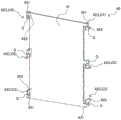
Fig. 2 is a perspective view of a detection member provided in a mobile phone according to an embodiment of the present invention.
Fig. 3 is a perspective view of a touch detection leg portion of the detection member.
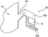
Fig. 4 is a perspective view of a grip detection leg portion of the detection member.
Fig. 5 is an explanatory diagram for explaining a method of calculating a touch position and a touch intensity.
Fig. 6 is an exploded perspective view of a cellular phone according to another embodiment of the present invention.
Fig. 7 is a perspective view of a detection member provided in a mobile phone according to another embodiment of the present invention.
Fig. 8 is an explanatory diagram for explaining a method of calculating the grip strength and the grip position.
Description of reference numerals:
10 … a frame body; 20 … control section; a 21 … sensor calculation unit (calculation unit); 30 … power supply; 40. 40' … detection feature; 41. 41' … frame; 42. 42' … touch-detecting leg portions; 421. 431 … a first plate portion; 422. 432 … second panel portion; 423. 433 … a third plate portion; 43. 43' … holding the leg for detection; a 50 … backlight; 60 … liquid crystal panel; 70 … transparent cover plate; a G … strain gauge; an SU … sensor unit; DU … display panel section.
Detailed Description
< first embodiment >
A cellular phone 100 according to a first embodiment of the present invention will be described with reference to fig. 1 to 5. The handset 100 is an example of a portable device of the present invention.
The cellular phone 100 according to the first embodiment mainly includes a housing 10, a control unit 20 and a power supply 30 housed inside the housing 10, a detection unit 40 covering the control unit 20 and the power supply 30, and a display panel unit DU attached to the detection unit 40. The display panel unit DU has a structure in which the backlight 50, the liquid crystal panel 60, and the transparent cover 70 are stacked in this order.
In the following description, the direction in which the housing 10, the detection member 40, and the display panel unit DU are superimposed is referred to as the front-rear direction of the cellular phone 100, the side where the transparent cover 70 is located is referred to as the front, and the side where the housing 10 is located is referred to as the rear.
The frame 10 has a rectangular back plate (back surface) 11 and four side plates (side surfaces) 12 that are respectively erected forward from four sides of the back plate 11. A power switch (not shown) for turning on the power of the mobile phone 100, a microphone (not shown) for making a call using the mobile phone 100, and the like are disposed on the side plate 12.
The control unit 20 is an integrated circuit housed inside the housing 10, and includes a CPU (not shown), a storage unit (not shown), a communication control unit (not shown), a sensor calculation unit 21 (calculation unit), and the like.
The power supply 30 is a secondary battery for supplying electric power to the control unit 20, the backlight 50, the liquid crystal panel 60, and the like, and may be a lithium ion battery as an example. The power supply 30 is housed inside the housing 10 adjacent to the control unit 20.
As shown in fig. 2, the detection member 40 includes a frame 41 that is a rectangular flat plate, four touch detection leg portions 42 provided at four corners of the frame 41, and two grip detection leg portions 43 provided on a pair of long sides of the frame 41. The detection member 40 is housed inside the housing 10 in a state where the four touch detection leg portions 42 are in contact with the back plate 11 of the housing 10 and the two grip detection leg portions 43 are in contact with the side plates 12 of the housing 10. The frame 41 is disposed in front of the control unit 20 and the power supply 30 so as to cover these components.
The sensor unit SU is constituted by the sensor arithmetic unit 21 of the control unit 20 and the detection unit 40. The detailed configuration and operation of the detection unit 40 and the sensor unit SU will be described later.
The backlight 50 of the display panel unit DU is attached to the front surface of the frame 41 of the detection member 40 with a double-sided tape, an adhesive, or the like. The backlight 50 includes a rectangular light guide plate 51 and a light source unit 52 provided along a short side of the light guide plate 51. A plurality of projections (not shown) are formed on the rear surface of the light guide plate 51. The plurality of convex portions are substantially hemispherical protrusions protruding outward (rearward) from the light guide plate 51, and are arranged over the entire rear surface of the light guide plate 51. The light emitted from the light source unit 52 is reflected forward by the plurality of convex portions, and is emitted from the front surface of the light guide plate 51 toward the liquid crystal panel 60.
The liquid crystal panel 60 of the display panel unit DU has a structure in which a polarizing filter, a color filter substrate, a liquid crystal layer, an array substrate, and the like, all of which are not shown, are stacked. The liquid crystal panel 60 modulates light from the backlight 50 and forms an image.
The transparent cover 70 of the display panel unit DU covers and seals the opening of the housing 10 to protect the liquid crystal panel 60 and the like, and is a rectangular plate made of glass or transparent resin, for example.
Next, the sensor unit SU provided in the mobile phone 100 according to the first embodiment will be described with reference to fig. 2 to 5.
As shown in fig. 2, the frame 41 of the detection unit 40 of the sensor unit SU is a rectangular flat plate, and can be formed of SUs or the like as an example.
As shown in fig. 3, the touch detection leg portions 42 provided at the four corners of the frame 41 are members that respectively bend and form portions protruding from the frame 41, and include a first plate portion 421, a second plate portion 422, and a third plate portion 423.
The first plate portion 421 is a substantially square flat plate connecting the frame 41 and the second plate portion 422. The first plate portion 421 protrudes laterally from the long side of the frame 41 and extends on the same plane as the frame 41.
The second plate portion 422 is a rectangular flat plate for mounting the strain gauge G, and the longitudinal direction of the second plate portion 422 is the same as the longitudinal direction of the frame 41, and the short-side direction of the second plate portion 422 is the same as the front-rear direction orthogonal to the frame 41. Therefore, the second plate portion 422 is positioned in a plane orthogonal to the frame 41 and extending in the longitudinal direction of the frame 41.
The second plate portion 422 is connected to the tip of the first plate portion 421 on the front side of one end portion in the longitudinal direction. Further, a third plate portion 423 is connected to the rear side of the other end portion in the longitudinal direction of the second plate portion 422.
Here, in the two touch detection legs 42, which are depicted in the upper side in fig. 1 and 2, of the four touch detection legs 42, the second plate portion 422 is connected to the tip of the first plate portion 421 on the front side of the upper end portion in the longitudinal direction, and is connected to the third plate portion 423 on the rear side of the lower end portion. In contrast, in the two touch detection leg portions 42 drawn downward in fig. 1 and 2, the second plate portion 422 is connected to the tip of the first plate portion 421 on the front side of the lower end portion in the longitudinal direction, and is connected to the third plate portion 423 on the rear side of the upper end portion. In other words, the four touch detection legs 42 are provided such that the first plate portion 421 is positioned on the end portion side in the longitudinal direction and the third plate portion 423 is positioned on the center side. This enables the positions of attachment of the two touch detection leg portions 42 attached to the same long side of the frame 41 to be greatly separated, and enables detection of a touch position to be described later in a wider range.
Strain gauges G (first strain gauges) are attached to both surfaces of the second plate portion 422 in the vicinity of the center portion in the longitudinal direction (more specifically, a position where shear stress due to touch is concentrated). The strain gauges G are connected to the sensor operation unit 21 of the control unit 20 by wiring lines not shown. According to the half-bridge structure using these two strain gauges G, the strain (shear strain described later) generated in the second plate portion 422 can be detected with about twice the sensitivity as compared with the case of using one strain gauge.
As shown in fig. 3, the third plate portion 423 has a substantially L-shape in which a flat plate extending rearward from the second plate portion 422 is bent so that a central portion in the front-rear direction protrudes toward the frame 41 side. The rear end of the third plate portion 423 contacts the inner surface side of the back plate 11 of the housing 10.
When a load is applied to the frame 41 from the front, the first plate portion 421 moves rearward while the third plate portion 423 is in contact with the housing 10, and thus shear strain is generated in the second plate portion 422 in each of the four touch detection legs 42. The sensor arithmetic unit 21 can detect the magnitude of the shear strain generated in the second plate portion 422 via the strain gauge G attached to the second plate portion 422, and can determine the magnitude of the load applied to each of the four touch detection leg portions 42 based on the magnitude of the shear strain. That is, four load sensors are configured by the sensor arithmetic unit 21 and each of the four touch detection leg portions 42.
Hereinafter, for convenience of explanation, in fig. 2, the load sensors constituted by the touch detection leg 42 and the sensor arithmetic unit 21 disposed on the upper right side as viewed from the front of the frame 41 are referred to as load sensors LC1, and the load sensors constituted by the touch detection leg 42 and the sensor arithmetic unit 21 disposed on the lower right, lower left, and upper left as viewed from the front of the frame 41 are referred to as load sensors LC2, LC3, and LC4, respectively.
As shown in fig. 4, the grip detection leg 43 provided near the center of the long side of the frame 41 is a member that bends and forms a portion protruding from the frame 41, and includes a first plate portion 431, a second plate portion 432, and a third plate portion 433.
The first plate portion 431 is a substantially square flat plate connecting the frame 41 and the second plate portion 432. The first plate portion 431 protrudes laterally from the long side of the frame 41, and extends on the same plane as the frame 41.
The second plate portion 432 is a rectangular flat plate for mounting the strain gauge G, and the longitudinal direction of the second plate portion 432 is the same as the longitudinal direction of the frame 41, and the short-side direction of the second plate portion 432 is the same as the front-rear direction orthogonal to the frame 41. Therefore, the second plate portion 432 is positioned in a plane orthogonal to the frame 41 and extending in the longitudinal direction of the frame 41. The second plate portion 432 is located on the same plane as the second plate portion 422 of the touch detection leg portion 42.
The second plate portion 432 is connected to the tip of the first plate portion 431 on the front side of one end portion in the longitudinal direction. Further, a third plate portion 433 is connected to the other end portion in the longitudinal direction of the second plate portion 432.
Strain gauges G (first strain gauges or second strain gauges) are attached to both surfaces of the second plate portion 432 in the vicinity of the center portion in the longitudinal direction (more specifically, a position where shear stress is generated by gripping). The strain gauges G are connected to the sensor operation unit 21 of the control unit 20 by wiring lines not shown. According to the half-bridge configuration using the two strain gauges G, the strain (bending strain described later) generated in the second plate portion 432 can be detected with about twice the sensitivity as compared with the case of using one strain gauge.
As shown in fig. 4, the third plate portion 433 has a substantially L-shape in which two plate portions that are orthogonal to the frame 41 and extend at a predetermined angle with respect to the second plate portion 432 are combined. The end of the third plate portion 433 opposite to the end connected to the second plate portion 432 is in contact with the inner surface side of the side surface 12 of the housing 10.
When a load is applied to the side plate 12 of the housing 10 from the side and the side plate 12 is flexed, the third plate portion 433 moves toward the frame 41 with the first plate portion 431 in contact with the frame 41, and bending strain is generated in the second plate portion 432 for each of the two grip detection legs 43. The sensor arithmetic unit 21 can detect the magnitude of the bending strain generated in the second plate portion 432 via the strain gauge G attached to the second plate portion 432, and can determine the magnitude of the load applied to each of the two grip detection leg portions 43 based on the magnitude of the bending strain. That is, two load sensors are configured by each of the two grip detection leg portions 43 and the sensor arithmetic section 21.
For convenience of explanation, in fig. 2, the load sensor LC5 is a load sensor constituted by the grip detection leg 43 and the sensor arithmetic unit 21 provided on the right side when the frame 41 is viewed from the front, and the load sensor LC6 is a load sensor constituted by the grip detection leg 43 and the sensor arithmetic unit 21 provided on the left side when the frame 41 is viewed from the front.
The first plate portion 421, the second plate portion 422, and the third plate portion 423 of the touch detection leg portion 42, and the first plate portion 431, the second plate portion 432, and the third plate portion 433 of the grip detection leg portion 43 are preferably integrally formed with the frame 41 from the same material. According to the above configuration, for example, when the first plate portion 421, the second plate portion 422, and the third plate portion 423 of the touch detection leg portion 42 and the first plate portion 431, the second plate portion 432, and the third plate portion 433 of the grip detection leg portion 43 are formed of a material different from that of the frame 41, the touch detection leg portion 42 is fixed to the frame 41 by welding or the like, and the grip detection leg portion 43 is fixed to the frame 41 by welding or the like, the fixing strength of the frame 41 and the touch detection leg portion 42 and the fixing strength of the frame 41 and the grip detection leg portion 43 can be secured, and irregular deformation of the connection portion can be reduced. Therefore, according to the above configuration, an effect of enabling highly accurate load detection can be achieved.
The detection member 40 may be held in the housing 10 in a state where the display panel unit DU is slightly biased rearward, as an example. At this time, the detection member 40 is held at a fixed position by frictional resistance between the distal end portion of the third plate portion 423 of the touch detection leg 42 and the inner surface of the back plate 11 of the housing 10.
Next, an operation of detecting a touch position and a touch intensity will be described using the sensor unit SU of the present embodiment.
In the present specification, the "touch position" broadly means a position where a user of a portable device (in the present embodiment, the mobile phone 100) touches the portable device, and specifically means, for example, a position where the user touches a monitor screen of the portable device. In the present embodiment, the "touch position" is a position where the user touches the transparent cover 70 of the cellular phone 100, and is a position where a load generated when the user touches the transparent cover 70 of the cellular phone 100 is applied to the frame 41.
In the present specification, the term "touch intensity" broadly means the intensity at which the user of the portable device (in the present embodiment, the mobile phone 100) touches the portable device, and specifically means, for example, the intensity at which the user presses the monitor screen of the portable device. In the present embodiment, the "touch intensity" is the intensity with which the user presses the transparent cover 70 of the cellular phone 100, and is the magnitude of the load applied to the frame 41 by the user pressing the transparent cover 70 of the cellular phone 100.
In the cellular phone 100 of the present embodiment, when the user touches the transparent cover 70 from the front, the pressing force of the user's finger pressing the transparent cover 70 to the rear is transmitted to the frame 41 of the detection member 40 via the liquid crystal panel 60 and the backlight 50, and a load is applied to the frame 41.
Here, the position of the frame 41 to which the load is applied and the magnitude of the applied load can be determined using the load sensors LC1 to LC 4. Specifically, for example, as shown in fig. 5, when the frame 41 is viewed from the front, the longitudinal direction (vertical direction) is defined as the X-axis direction, and the short-side direction (horizontal direction) is defined as the Y-axis direction. At this time, the coordinates of the load sensors LC1, LC2, LC3, and LC4 are (X)1,Y1)、(X2,Y2)、(X3,Y3)、(X4,Y4) And the detected values of the loads of the load sensors LC1, LC2, LC3 and LC4 are respectively W1、W2、W3、W4The sensor operation unit 21 calculates the center of gravity position (X, Y) on the frame 41, that is, the position (touch position) to which the load is applied, using the following formula.
Equation 1

Equation 2

The sensor operation unit 21 calculates the strength W of the load applied to the frame 41, i.e., the touch strength, using the following formula.
W=W1+W2+W3+W4
In the present embodiment, the third plate portion 433 of the grip detection leg portion 43 is in contact with the side plate 12 of the housing 10 in a state of being slidable in the front-rear direction. Therefore, when a load is applied to the frame 41 from the front and the frame 41 moves to the rear, the grip detection leg 43 moves the third plate portion 433 freely by sliding on the inner surface of the side plate 12 of the housing 10. Therefore, when a load is applied to the frame 41 from the front, the load sensors LC5 and LC6 do not detect the load, but the load is detected only by the load sensors LC1 to LC4, and the sensor arithmetic unit 21 can determine the touch position and the touch intensity using the equations 1, 2, and 3.
Next, the operation of detecting the grip strength will be described using the sensor unit SU of the present embodiment.
In the present specification, the term "grip strength" broadly means the strength with which a user of a portable device (in the present embodiment, the mobile phone 100) grips the portable device, and specifically means, for example, the strength with which the user grips the housing of the portable device. In the present embodiment, the "grip strength" is a strength with which the user grips the side plate 12 of the housing 10 of the cellular phone 100 and presses the side plate inward, and is a magnitude of a load applied to the side plate 12 by the user.
Therefore, in the cellular phone 100 of the present embodiment, the magnitude of the load detected by the load sensors LC5 and LC6 is the grip strength. The sum of the detection value of the load sensor LC5 and the detection value of the load sensor LC6 may be defined as "grip strength", and the detection value of the load sensor LC5 and the detection value of the load sensor LC6 may be handled as independent "grip strength", and one may be defined as right-side grip strength and the other may be defined as left-side grip strength, for example.
The effects of the cellular phone 100 of the present embodiment are summarized as follows.
The mobile phone 100 of the present embodiment can detect the touch position, the touch intensity, and the grip intensity by simply disposing the detection member 40 inside the housing 10 and constructing the sensor calculation unit 21 in the control unit 20. Therefore, the mobile phone 100 of the present embodiment can perform various detections with a simple configuration. Such various detections can provide a novel operation feeling to the portable device.
The frame 41 included in the detection unit 40 of the mobile phone 100 is a unit that is generally provided in a conventional mobile phone. Therefore, the mobile phone 100 of the present embodiment can detect the touch position, the touch intensity, and the grip intensity only by providing the four touch detection leg portions 42 and the two grip detection leg portions 43, which can be arranged in the dead space (dead space) in the mobile phone, as minute parts to the conventional mobile phone. That is, the mobile phone 100 of the present embodiment can provide a novel operation feeling to the mobile device while suppressing an increase in the number of components and complication of the device.
The mobile phone 100 of the present embodiment can detect a touch position and a touch intensity by the sensor unit SU including the detection unit 40 and the sensor arithmetic unit 21. Therefore, it is not necessary to use a touch panel of a resistive film method or a capacitive method, and the touch panel can be made thinner.
The cellular phone 100 of the present embodiment includes six load sensors LC1 to LC6, and thus can accurately detect the touch position, the touch strength, and the grip strength, and particularly can accurately detect the touch strength and the grip strength.
< second embodiment >
A cellular phone 200 according to a second embodiment of the present invention will be described with reference to fig. 6 and 7.
As shown in fig. 6, the mobile phone 200 of the second embodiment is the same as the mobile phone 100 of the first embodiment except that the shape of the detection member 40' is different from the detection member 40 of the mobile phone 100 of the first embodiment. Hereinafter, only the configuration of the detection member 40 'and the detection of the grasping position that can be performed by providing the detection member 40' will be described. The configuration and function not described are the same as those of the cellular phone 100 of the first embodiment.
As shown in fig. 7, the detection member 40 'has a frame 41' which is a rectangular flat plate, four touch detection leg portions 42 'provided at the four corners of the frame 41', and four grip detection leg portions 43 'provided adjacent to the four touch detection leg portions 42'. The shapes of the frame 41 ', the touch detection leg portion 42 ', and the grip detection leg portion 43 ' are the same as those of the frame 41, the touch detection leg portion 42, and the grip detection leg portion 43 of the first embodiment, respectively.
The detection member 40 ' is housed inside the housing 10 in a state where the four touch detection leg portions 42 ' are in contact with the back plate 11 of the housing 10 and the four grip detection leg portions 43 ' are in contact with the side plates 12 of the housing 10 so as to be slidable in the front-rear direction. The frame 41' is disposed in front of the control unit 20 and the power supply 30 so as to cover these components.
The strain gauges G attached to the four grip detection leg portions 43' are connected to the sensor operation unit 21 by unillustrated wiring. Hereinafter, in fig. 7, the load sensor including the grip detection leg portion 43 'provided on the upper right side when the frame 41' is viewed from the front and the sensor operation unit 21 is referred to as a load sensor LC 7. In fig. 7, the load sensors including the grip detection leg portion 43 'and the sensor arithmetic unit 21, which are provided on the lower right, lower left, and upper left sides of the frame 41' when viewed from the front, are referred to as load sensors LC8, LC9, and LC10, respectively.
In the cellular phone 200 according to the second embodiment, the load sensors are respectively constructed near both ends in the longitudinal direction of the frame 41', and thus the grip position can be detected in addition to the grip strength.
In the present specification, the "holding position" means, in a broad sense, a position at which a user of a portable device (in the present embodiment, the mobile phone 200) holds the portable device, and specifically, for example, means a position at which the user holds a housing of the portable device. In the present embodiment, the "holding position" is a position at which the user holds the side plate 12 of the housing 10 of the mobile phone 200, that is, a position at which the user applies a load to the side plate 12 of the housing 10 of the mobile phone 200.
An example of a method of detecting the grip strength and the grip position in the present embodiment is as follows. As shown in fig. 8, when the frame 41' is viewed from the front, the longitudinal direction (vertical direction) is defined as the X-axis direction, and the lateral direction (horizontal direction) is defined as the Y-axis direction. At this time, the X coordinate of the load sensor LC7 is defined as X7And the X coordinate of the load sensor LC8 is taken as X8And W represents the detected values of the loads of the load sensors LC7 and LC8 respectively7、W8The sensor operation unit 21 can calculate the application shown in fig. 8 by using the following formulaMagnitude W of holding force in + Y directionGI.e. the grip strength.
Equation 4
WG=W7+W8
The sensor operation unit 21 can calculate the position X in the X-axis direction to which the gripping force is applied by the following formulaGI.e. the gripping position.
Equation 5

The X coordinate of the load sensor LC9 can be defined as X for the grip strength and the grip position of the grip force applied in the-Y direction9And the X coordinate of LC10 is taken as X10And W represents the detected values of the loads of the load sensors LC9 and LC10 respectively9、W10And calculated using the same formulas as in formulas 4 and 5.
The cellular phone 200 according to the second embodiment can provide the same effects as those of the cellular phone 100 according to the first embodiment.
The mobile phone 200 of the second embodiment can detect the grip position by merely adding two minute parts, that is, the grip detection leg 43 that can be arranged in a quiet zone in the mobile phone, to the mobile phone 100 of the first embodiment, and thus can provide a novel operation feeling.
The following modifications can be used for the cellular phones 100 and 200 of the above embodiments.
The cellular phone 100 of the first embodiment and the cellular phone 200 of the second embodiment include both the touch detection leg portions 42 and 42 'and the grip detection leg portions 43 and 43', respectively, but are not limited thereto. The cellular phones 100 and 200 may be provided with only the touch detection leg portions 42 and 42 ', or only the grip detection leg portions 43 and 43'.
The mobile phone 100 of the first embodiment and the mobile phone 200 of the second embodiment each include four touch detection leg portions 42 and 42', respectively, but are not limited thereto. The number of the touch detection leg portions 42 and 42' provided in the cellular phones 100 and 200 is arbitrary. When only one touch detection leg 42, 42' is provided, although the touch position cannot be detected, the touch intensity can be detected. In addition, in the case where only two touch detection leg portions 42 and 42' are provided, the touch position and the touch intensity in the one-axis direction can be detected. In the case where three touch detection legs 42 and 42 'are provided, the touch positions and the touch intensities in the two axial directions can be detected without disposing these touch detection legs 42 and 42' on one axis.
In the cellular phone 100 of the first embodiment and the cellular phone 200 of the second embodiment, the touch detection leg portions 42 and 42 'are provided on the long sides of the frames 41 and 41', but the present invention is not limited thereto. The touch detection leg portions 42 and 42 'may be provided on the short sides of the frames 41 and 41'.
The touch detection leg portions 42 and 42 'are not necessarily provided at the corners of the frames 41 and 41'. The positions of the touch detection leg portions 42 and 42' can be set as appropriate so that the touch intensity and the touch position can be detected in a desired region.
In the present specification, "the vicinity of the four corners" of the frame 41, 41 'means a position where the distance to the corner is shorter than the distance to the center in the longitudinal direction of the frame 41, 41', and preferably means a point where the distance between one end in the longitudinal direction and the center is D and the point is located within (1/4) D from the one end. In addition, the position where the distance to the corner portion is shorter than the distance to the center portion in the short side direction of the frame 41, 41' is meant, and preferably, the position where the distance between the one end portion in the short side direction and the center portion is d and is within (1/4) d from the one end portion is meant.
In the cellular phone 100 of the first embodiment and the cellular phone 200 of the second embodiment, the grip detection leg portions 43 and 43 'are provided on the long sides of the frames 41 and 41', but the grip detection leg portions 43 and 43 'may be provided on the short sides of the frames 41 and 41'. The positions of the grip detection leg portions 43 and 43 'provided on the long side and the short side of the frames 41 and 41' are also arbitrary. The grip detection leg portions 43 and 43 'may be provided only on one of the pair of long sides of the frames 41 and 41', or may be provided only on one of the pair of short sides.
The first plate portion 421 is orthogonal to the second plate portion 422 in the touch detection leg portion 42 provided in the detection means 40 of the mobile phone 100 according to the first embodiment and the touch detection leg portion 42 'provided in the detection means 40' of the mobile phone 200 according to the second embodiment, but the present invention is not limited thereto. The first plate portion 421 and the second plate portion 422 may intersect at a predetermined angle.
The strain gauges G are attached to both surfaces of the second plate portion 422 in the touch detection leg portion 42 of the detection member 40 of the mobile phone 100 according to the first embodiment and the touch detection leg portion 42 'of the detection member 40' of the mobile phone 200 according to the second embodiment, but the present invention is not limited thereto. The strain gauge G may be attached to only one surface of the second plate 422. Alternatively, for example, by using a full-bridge configuration of four strain gauges G, the shear strain generated in the second plate portion 422 can be detected with a sensitivity approximately four times as high as that in the case of using one strain gauge.
The strain gauge G may be attached to both surfaces or one surface of the first plate portion 421, instead of the second plate portion 422. When a load is applied to the frame 41 or the frame 41', a bending strain is also generated in the first plate portion 421, and thus a load sensor can be constructed by the strain sensor G attached to the first plate portion 421 and the sensor operation portion 21.
The touch detection leg 42 of the detection member 40 of the mobile phone 100 according to the first embodiment and the touch detection leg 42 'of the detection member 40' of the mobile phone 200 according to the second embodiment may not have the second plate portion 422 and the third plate portion 423, but may have only the first plate portion 421 to which the strain gauge G is attached. In this case, the end portion of the first plate portion 421 may be attached to the inner surface side of the side plate 12 of the housing 10.
Even in the case of the touch detection leg portions 42 and 42 ', when a load is applied to the frames 41 and 41', a bending strain is generated in the first plate portion 421, and thus a load sensor can be constructed together with the sensor operation portion 21.
The shapes of the first plate portion 421, the second plate portion 422, and the third plate portion 423 are arbitrary in the touch detection leg portion 42 provided in the detection member 40 of the mobile phone 100 according to the first embodiment and the touch detection leg portion 42 'provided in the detection member 40' of the mobile phone 200 according to the second embodiment. For example, the first plate portion 421 may be not substantially square but substantially rectangular, and the second plate portion 422 may be not substantially rectangular but substantially square. The third plate portion 423 may be flat plate-shaped, for example.
The touch detection leg 42 and the grip detection leg 43 of the detection member 40 of the mobile phone 100 according to the first embodiment and the touch detection leg 42 ' and the grip detection leg 43 ' of the detection member 40 ' of the mobile phone 200 according to the second embodiment are each formed of a plurality of plate-like members, but are not limited thereto. For example, the first plate portions 421 and 431 and the third plate portions 423 and 433 may have a cylindrical shape or a prismatic shape. Similarly, the second plate portions 422 and 432 are not limited to a plate shape as long as they can mount the strain gauge G, and may be formed in a cylindrical shape or a prismatic shape, for example.
The first plate portion 431 and the second plate portion 432 are orthogonal to each other in the grip detection leg portion 43 of the detection member 40 of the mobile phone 100 according to the first embodiment and the grip detection leg portion 43 'of the detection member 40' of the mobile phone 200 according to the second embodiment, but the present invention is not limited thereto. The first plate portion 431 and the second plate portion 432 may intersect at a predetermined angle.
The strain gauges G are attached to both surfaces of the second plate portion 432 in the grip detection leg portion 43 of the detection member 40 of the mobile phone 100 according to the first embodiment and the grip detection leg portion 43 'of the detection member 40' of the mobile phone 200 according to the second embodiment, but the present invention is not limited thereto. The strain gauge G may be attached to only one surface of the second plate portion 432. Alternatively, for example, a full-bridge configuration using four strain gauges G may be used, and the bending strain generated in the second plate portion 432 can be detected with a sensitivity approximately four times as high as that in the case of using one strain gauge.
The strain gauge G may be attached to both surfaces or one surface of the first plate portion 431, instead of the second plate portion 432. When a load is applied to the side plate 12 of the housing 10, a shear strain is also generated in the first plate portion 431, and thus a load sensor can be constructed by the strain sensor G attached to the first plate portion 431 and the sensor arithmetic portion 21.
The shapes of the first plate portion 431, the second plate portion 432, and the third plate portion 433 are arbitrary in the grip detection leg portion 43 of the detection member 40 of the mobile phone 100 according to the first embodiment and the grip detection leg portion 43 'of the detection member 40' of the mobile phone 200 according to the second embodiment. For example, the first plate portion 431 may be not substantially square but substantially rectangular, and the second plate portion 432 may be not substantially rectangular but substantially square. The third plate portion 433 may be a flat plate, for example.
The frame 41 of the detection member 40 of the mobile phone 100 according to the first embodiment and the frame 41 'of the detection member 40' of the mobile phone 200 according to the second embodiment are not limited to rectangular plates. The frames 41, 41' may be any shape such as a square, other polygon, circle, or oval.
The cellular phone 100 according to the first embodiment and the cellular phone 200 according to the second embodiment may further include a touch panel of another type such as a resistive film type or a capacitive type.
The first and second embodiments have been described with reference to a mobile phone as an example of a mobile device, but the mobile device including the sensor unit SU of the above embodiments is not limited to a mobile phone. For example, the sensor unit SU of the above embodiment can be used in a portable game machine, a mobile music playback device, a notebook computer, a tablet computer, or the like.
The present invention is not limited to the above-described embodiments as long as the features of the present invention are maintained, and other embodiments considered within the scope of the technical idea of the present invention are also included in the scope of the present invention. For example, the present invention also includes the above-described detecting means (i.e., a frame mechanism/structure including a frame and at least one of a touch detection leg portion and a grip detection leg portion), a sensor unit including the detecting means and a sensor arithmetic unit, and the like.
Industrial applicability of the invention
According to the present invention, a novel operation feeling can be given to a mobile device such as a mobile phone.
Claims (3)
1. A portable device capable of detecting a grip strength when a user grips the portable device,
it is characterized in that the preparation method is characterized in that,
the portable device is provided with:
a frame body having a back surface and a side surface and accommodating the holding detection leg portion;
a rectangular frame on which the display panel portion is placed;
a first grip detection leg portion extending from a long side of the frame and contacting the side surface inside the frame;
a first strain gauge attached to a position of a first grip detection leg portion where strain is generated by the user gripping the portable device; and
a calculation unit for calculating the grip strength based on the output of the first strain gauge,
the first grip detection leg includes a first member to which a first strain gauge is attached, a second member connecting the first member and the frame, and a third member connected to the first member and contacting the side surface of the frame,
the grip strength is a strength of a force applied to the portable device in a short side direction of the frame by a user who grips the portable device.
2. The portable device of claim 1,
the portable device further includes:
a second grip detection leg portion extending from a long side of the frame and contacting the side surface inside the frame; and
a second strain gauge attached to a position of a second grip-detection leg portion where strain is generated by the user gripping the portable device,
the second grip detection leg includes a first member to which a second strain gauge is attached, a second member connecting the first member and the frame, and a third member connected to the first member and contacting the side surface of the frame,
when the load detection value by the first strain gauge is W1, the load detection value by the second strain gauge is W2, the position of the first grip detecting leg is X1, the position of the second grip detecting leg is X2, and the grip position when the user grips the housing is X,
the calculation unit calculates a holding position when the user holds the housing, based on X ═ X1 × W1+ X2 × W2)/(W1+ W2.
3. The portable device of claim 1,
the rectangular frame and the first grip detection leg portion are integrally formed of the same material.
Applications Claiming Priority (3)
| Application Number | Priority Date | Filing Date | Title |
|---|---|---|---|
| JP2015-250471 | 2015-12-22 | ||
| JP2015250471A JP6470674B2 (en) | 2015-12-22 | 2015-12-22 | Portable device |
| CN201611182024.9A CN107015597B (en) | 2015-12-22 | 2016-12-20 | Portable device |
Related Parent Applications (1)
| Application Number | Title | Priority Date | Filing Date |
|---|---|---|---|
| CN201611182024.9A Division CN107015597B (en) | 2015-12-22 | 2016-12-20 | Portable device |
Publications (2)
| Publication Number | Publication Date |
|---|---|
| CN110471497A CN110471497A (en) | 2019-11-19 |
| CN110471497B true CN110471497B (en) | 2021-03-12 |
Family
ID=59066229
Family Applications (2)
| Application Number | Title | Priority Date | Filing Date |
|---|---|---|---|
| CN201910614514.9A Active CN110471497B (en) | 2015-12-22 | 2016-12-20 | Portable device |
| CN201611182024.9A Active CN107015597B (en) | 2015-12-22 | 2016-12-20 | Portable device |
Family Applications After (1)
| Application Number | Title | Priority Date | Filing Date |
|---|---|---|---|
| CN201611182024.9A Active CN107015597B (en) | 2015-12-22 | 2016-12-20 | Portable device |
Country Status (3)
| Country | Link |
|---|---|
| US (2) | US10114506B2 (en) |
| JP (1) | JP6470674B2 (en) |
| CN (2) | CN110471497B (en) |
Families Citing this family (4)
| Publication number | Priority date | Publication date | Assignee | Title |
|---|---|---|---|---|
| US10782818B2 (en) | 2018-08-29 | 2020-09-22 | Apple Inc. | Load cell array for detection of force input to an electronic device enclosure |
| US10999421B1 (en) | 2019-12-17 | 2021-05-04 | Robert Bosch Gmbh | System and method for utilizing pressure sensors in an electric device |
| US10812639B1 (en) | 2019-12-17 | 2020-10-20 | Robert Bosch Gmbh | Pressure chamber and associated pressure sensors for a mobile communication device |
| US11789540B1 (en) * | 2022-11-23 | 2023-10-17 | Kostal Of America, Inc. | Touch surface controller |
Citations (1)
| Publication number | Priority date | Publication date | Assignee | Title |
|---|---|---|---|---|
| US9626029B2 (en) * | 2013-06-20 | 2017-04-18 | Samsung Electronics Co., Ltd | Electronic device and method of controlling electronic device using grip sensing |
Family Cites Families (18)
| Publication number | Priority date | Publication date | Assignee | Title |
|---|---|---|---|---|
| US5241308A (en) * | 1990-02-22 | 1993-08-31 | Paragon Systems, Inc. | Force sensitive touch panel |
| US5742222A (en) * | 1995-05-26 | 1998-04-21 | Avi Systems, Inc. | Direct adhering polysilicon based strain gage |
| US5708460A (en) * | 1995-06-02 | 1998-01-13 | Avi Systems, Inc. | Touch screen |
| JP2006126997A (en) | 2004-10-27 | 2006-05-18 | Pfu Ltd | Three-dimensional touch panel |
| JP2007086990A (en) * | 2005-09-21 | 2007-04-05 | Smk Corp | Touch panel |
| WO2008076393A1 (en) * | 2006-12-14 | 2008-06-26 | Qsi Corporation | Force-based input device having a modular sensing component |
| JP5453351B2 (en) * | 2011-06-24 | 2014-03-26 | 株式会社Nttドコモ | Mobile information terminal, operation state determination method, program |
| JP5588931B2 (en) * | 2011-06-29 | 2014-09-10 | 株式会社Nttドコモ | Mobile information terminal, arrangement area acquisition method, program |
| US9880653B2 (en) * | 2012-04-30 | 2018-01-30 | Corning Incorporated | Pressure-sensing touch system utilizing total-internal reflection |
| KR101995486B1 (en) * | 2012-06-26 | 2019-07-02 | 엘지전자 주식회사 | Mobile terminal and control method thereof |
| US9952703B2 (en) * | 2013-03-15 | 2018-04-24 | Apple Inc. | Force sensing of inputs through strain analysis |
| WO2014171606A1 (en) * | 2013-04-19 | 2014-10-23 | Lg Electronics Inc. | Device for controlling mobile terminal and method of controlling the mobile terminal |
| KR102153006B1 (en) * | 2013-05-27 | 2020-09-07 | 삼성전자주식회사 | Method for processing input and an electronic device thereof |
| JP5904174B2 (en) * | 2013-08-22 | 2016-04-13 | Smk株式会社 | Touch panel support structure |
| US10691332B2 (en) * | 2014-02-28 | 2020-06-23 | Samsung Electronics Company, Ltd. | Text input on an interactive display |
| CN104977994B (en) * | 2014-04-10 | 2018-02-13 | 台达电子工业股份有限公司 | Buckle module and its cabinet being applicable |
| JP6291340B2 (en) * | 2014-05-07 | 2018-03-14 | 富士ソフト株式会社 | Touch input device and input detection method |
| JP6120898B2 (en) * | 2015-03-27 | 2017-04-26 | 京セラ株式会社 | Electronic device and control method of electronic device |
-
2015
- 2015-12-22 JP JP2015250471A patent/JP6470674B2/en active Active
-
2016
- 2016-12-16 US US15/381,897 patent/US10114506B2/en active Active
- 2016-12-20 CN CN201910614514.9A patent/CN110471497B/en active Active
- 2016-12-20 CN CN201611182024.9A patent/CN107015597B/en active Active
-
2018
- 2018-07-02 US US16/025,394 patent/US10216326B2/en active Active
Patent Citations (1)
| Publication number | Priority date | Publication date | Assignee | Title |
|---|---|---|---|---|
| US9626029B2 (en) * | 2013-06-20 | 2017-04-18 | Samsung Electronics Co., Ltd | Electronic device and method of controlling electronic device using grip sensing |
Also Published As
| Publication number | Publication date |
|---|---|
| CN107015597B (en) | 2019-08-16 |
| US10114506B2 (en) | 2018-10-30 |
| US20170177152A1 (en) | 2017-06-22 |
| JP6470674B2 (en) | 2019-02-13 |
| CN110471497A (en) | 2019-11-19 |
| US20180321789A1 (en) | 2018-11-08 |
| CN107015597A (en) | 2017-08-04 |
| JP2017117124A (en) | 2017-06-29 |
| US10216326B2 (en) | 2019-02-26 |
Similar Documents
| Publication | Publication Date | Title |
|---|---|---|
| CN110471497B (en) | Portable device | |
| US8755175B2 (en) | Operation device | |
| JP5610656B2 (en) | Portable electronic devices | |
| CN204375609U (en) | A kind of button and electronic equipment | |
| JP4682357B2 (en) | Interface device with haptic touch panel | |
| US9909852B2 (en) | Operation position detection apparatus and vehicular apparatus | |
| KR20130002126A (en) | Support structure for a touch panel | |
| US8878805B2 (en) | Touch panel vibrator with reduced reflectance | |
| JP2014115321A (en) | Display device | |
| EP2555092B1 (en) | Electronic appliance and mobile terminal provided with same | |
| JP6528013B2 (en) | Mobile device | |
| CN108521479B (en) | Display screen assembly and electronic equipment | |
| CN217655907U (en) | Piezoelectric sensor and electronic device | |
| US8823638B2 (en) | Optical navigation module with alignment features | |
| KR20130085207A (en) | Touch panel based on pressing force | |
| JP2015070366A (en) | Portable terminal device | |
| JP2014139742A (en) | Vibration device and electronic apparatus | |
| WO2013084820A1 (en) | Electronic apparatus | |
| CN216122502U (en) | Electronic equipment material preparing shell assembly and electronic equipment | |
| JP2013008151A (en) | Electronic apparatus and portable terminal with the same | |
| WO2015141314A1 (en) | Terminal device | |
| KR20220017325A (en) | Electronic device with wireless charging | |
| CA2764979C (en) | Optical navigation module with alignment features | |
| JP2016225815A (en) | Housing for portable terminal and portable terminal | |
| JP2012088264A (en) | Pressure detection device and electronic apparatus |
Legal Events
| Date | Code | Title | Description |
|---|---|---|---|
| PB01 | Publication | ||
| PB01 | Publication | ||
| SE01 | Entry into force of request for substantive examination | ||
| SE01 | Entry into force of request for substantive examination | ||
| GR01 | Patent grant | ||
| GR01 | Patent grant |