CN110463277B - Reliable transfer of system information - Google Patents
Reliable transfer of system information Download PDFInfo
- Publication number
- CN110463277B CN110463277B CN201880022294.4A CN201880022294A CN110463277B CN 110463277 B CN110463277 B CN 110463277B CN 201880022294 A CN201880022294 A CN 201880022294A CN 110463277 B CN110463277 B CN 110463277B
- Authority
- CN
- China
- Prior art keywords
- requested
- indication
- transmission
- ues
- time period
- Prior art date
- Legal status (The legal status is an assumption and is not a legal conclusion. Google has not performed a legal analysis and makes no representation as to the accuracy of the status listed.)
- Active
Links
Images


Classifications
-
- H—ELECTRICITY
- H04—ELECTRIC COMMUNICATION TECHNIQUE
- H04W—WIRELESS COMMUNICATION NETWORKS
- H04W72/00—Local resource management
- H04W72/20—Control channels or signalling for resource management
- H04W72/23—Control channels or signalling for resource management in the downlink direction of a wireless link, i.e. towards a terminal
-
- H—ELECTRICITY
- H04—ELECTRIC COMMUNICATION TECHNIQUE
- H04L—TRANSMISSION OF DIGITAL INFORMATION, e.g. TELEGRAPHIC COMMUNICATION
- H04L1/00—Arrangements for detecting or preventing errors in the information received
- H04L1/12—Arrangements for detecting or preventing errors in the information received by using return channel
- H04L1/16—Arrangements for detecting or preventing errors in the information received by using return channel in which the return channel carries supervisory signals, e.g. repetition request signals
- H04L1/18—Automatic repetition systems, e.g. Van Duuren systems
-
- H—ELECTRICITY
- H04—ELECTRIC COMMUNICATION TECHNIQUE
- H04W—WIRELESS COMMUNICATION NETWORKS
- H04W48/00—Access restriction; Network selection; Access point selection
- H04W48/08—Access restriction or access information delivery, e.g. discovery data delivery
- H04W48/12—Access restriction or access information delivery, e.g. discovery data delivery using downlink control channel
-
- H—ELECTRICITY
- H04—ELECTRIC COMMUNICATION TECHNIQUE
- H04W—WIRELESS COMMUNICATION NETWORKS
- H04W72/00—Local resource management
- H04W72/04—Wireless resource allocation
- H04W72/044—Wireless resource allocation based on the type of the allocated resource
- H04W72/0446—Resources in time domain, e.g. slots or frames
-
- H—ELECTRICITY
- H04—ELECTRIC COMMUNICATION TECHNIQUE
- H04W—WIRELESS COMMUNICATION NETWORKS
- H04W74/00—Wireless channel access, e.g. scheduled or random access
- H04W74/08—Non-scheduled or contention based access, e.g. random access, ALOHA, CSMA [Carrier Sense Multiple Access]
- H04W74/0833—Non-scheduled or contention based access, e.g. random access, ALOHA, CSMA [Carrier Sense Multiple Access] using a random access procedure
-
- H—ELECTRICITY
- H04—ELECTRIC COMMUNICATION TECHNIQUE
- H04L—TRANSMISSION OF DIGITAL INFORMATION, e.g. TELEGRAPHIC COMMUNICATION
- H04L1/00—Arrangements for detecting or preventing errors in the information received
- H04L1/12—Arrangements for detecting or preventing errors in the information received by using return channel
- H04L1/16—Arrangements for detecting or preventing errors in the information received by using return channel in which the return channel carries supervisory signals, e.g. repetition request signals
- H04L1/18—Automatic repetition systems, e.g. Van Duuren systems
- H04L1/1867—Arrangements specially adapted for the transmitter end
- H04L1/1896—ARQ related signaling
-
- H—ELECTRICITY
- H04—ELECTRIC COMMUNICATION TECHNIQUE
- H04L—TRANSMISSION OF DIGITAL INFORMATION, e.g. TELEGRAPHIC COMMUNICATION
- H04L1/00—Arrangements for detecting or preventing errors in the information received
- H04L2001/0092—Error control systems characterised by the topology of the transmission link
- H04L2001/0093—Point-to-multipoint
-
- H—ELECTRICITY
- H04—ELECTRIC COMMUNICATION TECHNIQUE
- H04W—WIRELESS COMMUNICATION NETWORKS
- H04W48/00—Access restriction; Network selection; Access point selection
- H04W48/08—Access restriction or access information delivery, e.g. discovery data delivery
- H04W48/14—Access restriction or access information delivery, e.g. discovery data delivery using user query or user detection
Abstract
Certain aspects of the present disclosure relate to methods and apparatus for reliable transmission of System Information (SI). In some cases, the UE may send an indication to request the SI in an on-demand manner. For example, a method for wireless communication of a UE may comprise: it is determined that System Information (SI) desired by the UE is not currently broadcast. In addition, the method further comprises: in response to the determination, sending a first indication to request the SI; transmitting a second indication for confirming that the requested SI has been received or indicating that the UE has not received the requested SI after a time period.
Description
Cross Reference to Related Applications
This patent application claims priority to us provisional patent application No.62/480,290 filed on 3/31/2017 and us patent application No.15/905,425 filed on 26/2/2018, both of which have been assigned to the assignee of the present application and are hereby expressly incorporated herein in their entirety by reference.
Technical Field
The present disclosure relates generally to wireless communication systems, and more particularly to methods and apparatus for reliable transmission of system information in such systems.
Background
Wireless communication systems have been widely deployed to provide various telecommunication services such as telephony, video, data, messaging, and broadcasting. A typical wireless communication system may employ multiple-access techniques that can support communication with multiple users by sharing the available system resources (e.g., bandwidth, transmit power). Examples of such multiple-access techniques include Long Term Evolution (LTE) systems, Code Division Multiple Access (CDMA) systems, Time Division Multiple Access (TDMA) systems, Frequency Division Multiple Access (FDMA) systems, Orthogonal Frequency Division Multiple Access (OFDMA) systems, single carrier frequency division multiple access (SC-FDMA) systems, and time division synchronous code division multiple access (TD-SCDMA) systems.
In some examples, a wireless multiple-access communication system may include multiple base stations, each supporting communication for multiple communication devices (otherwise known as User Equipment (UE)) simultaneously. In an LTE or LTE-a network, a group of one or more base stations may specify an enodeb (enb). In other examples (e.g., in a next generation or 5G network), a wireless multiple-access communication system may include a plurality of Distributed Units (DUs) (e.g., Edge Units (EUs), Edge Nodes (ENs), Radio Heads (RHs), intelligent radio heads (SRHs), Transmission Reception Points (TRPs), etc.) in communication with a plurality of Central Units (CUs) (e.g., Central Nodes (CNs), Access Node Controllers (ANCs), etc.), wherein a set of one or more distributed units in communication with a central unit may specify an access node (e.g., a new radio base station (NR BS), a new radio node b (NR NB), a network node, a 5G NB, an eNB, a next generation node b (gnb), etc.). A base station or DU may communicate with a group of UEs on downlink channels (e.g., for transmissions from the base station or to the UEs) and uplink channels (e.g., for transmissions from the UEs to the base station or distributed units).
These multiple access techniques have been adopted in various telecommunications standards to provide a common protocol that enables different wireless devices to communicate on a city-wide, country-wide, regional, or even global scale. An example of an emerging telecommunications standard is the New Radio (NR), e.g. 5G radio access. NR is an evolved set of LTE mobile standards promulgated by the third generation partnership project (3 GPP). NR is designed to better support mobile broadband internet access by improving spectral efficiency, reducing costs, improving services, making full use of new spectrum, better integrating with other open standards using OFDMA and Cyclic Prefix (CP) on Downlink (DL) and Uplink (UL), and supporting beamforming, multiple-input multiple-output (MIMO) antenna technology, and carrier aggregation.
However, as the demand for mobile broadband access continues to increase, there is a desire to further improve NR technology. Preferably, these improvements are also applicable to other multiple access techniques and communication standards employing these techniques.
Disclosure of Invention
The systems, methods, and devices of the present disclosure all have some aspects, but no single one of these aspects may be solely responsible for its desirable attributes. The claims set forth below do not limit the scope of the present disclosure, and some features will now be discussed briefly. After considering this discussion, and particularly after reading the section entitled "detailed description of certain embodiments" one will understand how the features of this disclosure have advantages that include: improved communication between an access point and a station in a wireless network.
Certain aspects provide a method for wireless communication of a user equipment. Generally, the method comprises: determining that System Information (SI) desired by the UE is not currently broadcast; in response to the determination, sending a first indication for requesting the System Information (SI); transmitting a second indication for confirming that the requested SI has been received or indicating that the UE has not received the requested SI after a time period.
Certain aspects provide a method for wireless communication of a base station. Generally, the method comprises: receiving a first indication as a request for System Information (SI) from one or more user equipments; transmitting the SI in response to the first indication; monitoring a second indication for confirming that one or more UEs received the requested SI or determining that at least one of the one or more UEs has not received the requested SI after a period of time; deciding whether to continue sending the SI based on the monitoring.
In general, aspects herein include methods, apparatuses, systems, computer-readable media, and processing systems substantially as described herein with reference to and as illustrated by the accompanying drawings.
To the accomplishment of the foregoing and related ends, the one or more aspects comprise the features hereinafter fully described and particularly pointed out in the claims. The following description and the annexed drawings set forth in detail certain illustrative features of the one or more aspects. These features are indicative, however, of but a few of the various ways in which the principles of these various aspects may be employed and the description is intended to include all such aspects and their equivalents.
Drawings
In order that the manner in which the above-recited features of the present disclosure are attained and can be understood in detail, a more particular description is given above briefly summarized above with reference to the aspects that are illustrated in the appended drawings. It is to be noted, however, that the appended drawings illustrate only certain typical aspects of this disclosure and are therefore not to be considered limiting of its scope, for the invention may admit to other equally effective aspects.
Figure 1 is a block diagram conceptually illustrating an exemplary telecommunications system, in accordance with certain aspects of the present disclosure.
Fig. 2 is a block diagram illustrating an exemplary logical architecture of a distributed RAN, in accordance with certain aspects of the present disclosure.
Fig. 3 is a block diagram illustrating an example physical architecture of a distributed RAN, in accordance with certain aspects of the present disclosure.
Fig. 4 is a block diagram conceptually illustrating a design of an exemplary BS and User Equipment (UE), in accordance with certain aspects of the present disclosure.
Fig. 5 is a diagram illustrating an example for implementing a communication protocol stack, in accordance with certain aspects of the present disclosure.
Fig. 6 illustrates an example of a DL centric sub-frame, in accordance with certain aspects of the present disclosure.
Fig. 7 illustrates an example of a UL centric sub-frame, in accordance with certain aspects of the present disclosure.
Fig. 8 illustrates example operations for wireless communications of a User Equipment (UE), in accordance with aspects of the present disclosure.
Fig. 8A illustrates exemplary components capable of performing the operations illustrated in fig. 8, in accordance with aspects of the present disclosure.
Fig. 9 illustrates example operations for wireless communications of a base station, in accordance with aspects of the present disclosure.
Fig. 9A illustrates exemplary components capable of performing the operations illustrated in fig. 9, in accordance with aspects of the present disclosure.
Fig. 10 illustrates an example of one method for reliable communication of system information in accordance with aspects of the present disclosure.
FIG. 11 illustrates an example of one method for reliable communication of system information in accordance with aspects of the present disclosure.
To facilitate understanding, identical reference numerals have been used, where possible, to designate identical elements that are common to the figures. It should be appreciated that elements disclosed in one aspect may be beneficially utilized on other aspects without specific recitation.
Detailed Description
Aspects of the present disclosure provide apparatuses, methods, processing systems, and computer-readable media for a New Radio (NR) (new radio access technology or 5G technology).
NR may support various wireless communication services, such as enhanced mobile broadband (eMBB) targeted for wider bandwidths (e.g., above 80 MHz), millimeter wave (mmW) targeted for high carrier frequencies (e.g., 27GHz or above), massive MTC (MTC) targeted for non-backward compatible MTC technologies, and/or mission critical targeted for ultra-reliable low-latency communication (URLLC). These services may include latency and reliability requirements. These services may also have different Transmission Time Intervals (TTIs) to meet corresponding quality of service (QoS) requirements. Furthermore, these services may coexist in the same subframe.
The following description provides examples, but does not limit the scope, applicability, or examples set forth in the claims. Changes may be made in the function and arrangement of elements discussed without departing from the scope of the disclosure. Various examples may omit, substitute, or add various procedures or components as necessary. For example, the methods described may be performed in a different order than described, with various steps added, omitted, or combined. Furthermore, features described with respect to some examples may be combined into other examples. For example, an apparatus may be implemented or a method may be implemented using any number of the aspects set forth herein. Moreover, the scope of the present disclosure is intended to cover such apparatus or methods, which may be implemented by using other structure, functionality, or structure and functionality in addition to or other than the various aspects of the present disclosure as set forth herein. It should be understood that any aspect of the disclosure described herein may be embodied by one or more components of the invention. The word "exemplary" is used herein to mean "serving as an example, instance, or illustration. Any aspect described herein as "exemplary" is not necessarily to be construed as preferred or advantageous over other aspects.
The techniques described herein may be used for various wireless communication networks, such as LTE, CDMA, TDMA, FDMA, OFDMA, SC-FDMA, and other networks. The terms "network" and "system" are often used interchangeably. A CDMA network may implement a radio technology such as Universal Terrestrial Radio Access (UTRA), CDMA2000, and so on. UTRA includes wideband CDMA (wcdma) and other variants of CDMA. CDMA2000 covers IS-2000, IS-95 and IS-856 standards. TDMA networks may implement wireless technologies such as global system for mobile communications (GSM). An OFDMA network may implement wireless technologies such as NR (e.g., 5G RA), evolved UTRA (E-UTRA), Ultra Mobile Broadband (UMB), IEEE 802.11(Wi-Fi), IEEE 802.16(WiMAX), IEEE 802.20, Flash-OFDMA, and so on. UTRA and E-UTRA are part of the Universal Mobile Telecommunications System (UMTS). NR is an emerging wireless communication technology deployed in conjunction with the 5G technology forum (5 GTF). 3GPP Long Term Evolution (LTE) and LTE-advanced (LTE-A) are new releases of UMTS that employ E-UTRA. UTRA, E-UTRA, UMTS, LTE-A, and GSM are described in documents from an organization named "third Generation partnership project" (3 GPP). CDMA2000 and UMB are described in documents from an organization named "third generation partnership project 2" (3GPP 2). "LTE" generally refers to LTE, LTE-advanced (LTE-a), LTE in unlicensed spectrum (LTE-free space), and so on. The techniques described herein may be used for the wireless networks and wireless technologies mentioned above as well as other wireless networks and wireless technologies. For clarity of explanation, although aspects are described herein using terms commonly associated with 3G and/or 4G wireless technologies, aspects of the present disclosure may also be applied to other generation-based communication systems (e.g., 5G and beyond, including NR technologies).
Exemplary Wireless communication System
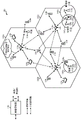
Fig. 1 illustrates an example wireless network 100 (e.g., a New Radio (NR) or 5G network) in which aspects of the disclosure may be implemented in the wireless network 100.
As shown in fig. 1, wireless network 100 may include multiple BSs 110 and other network entities. The BS may be a station communicating with the UE. Each BS 110 may provide communication coverage for a particular geographic area. In 3GPP, the term "cell" can refer to a coverage area of a node B and/or a node B subsystem serving the coverage area, depending on the context in which the term is used. In an NR system, the term "cell" and eNB, nodeb, 5G NB, AP, NR BS, gNB, or TRP may be interchangeable. In some examples, the cell need not be stationary, and the geographic region of the cell may be moved based on the location of the mobile base station. In some examples, the base stations may be interconnected to each other and/or to one or more other base stations or network nodes (not shown) in wireless network 100 through various types of backhaul interfaces (such as direct physical connections, virtual networks, etc.), using any suitable transport network.
In general, any number of wireless networks may be deployed in a given geographic area. Each wireless network may support a particular Radio Access Technology (RAT), and may operate on one or more frequencies. A RAT may also be referred to as a radio technology, air interface, etc. Frequencies may also be referred to as carriers, frequency channels, and so on. Each frequency may support a single RAT in a given geographic area in order to avoid interference between wireless networks of different RATs. In some cases, NR or 5G RAT networks may be deployed.
The BS may provide communication coverage for a macro cell, pico cell, femto cell, and/or other types of cells. A macro cell may cover a relatively large geographic area (e.g., several kilometers in radius) that allows unrestricted access by UEs with service subscriptions. A pico cell may cover a relatively small geographic area that allows unrestricted access by UEs with service subscriptions. A femto cell may cover a relatively small geographic area (e.g., a home) that allows restricted access by UEs having an association with the femto cell (e.g., UEs in a Closed Subscriber Group (CSG), UEs for users in the home, etc.). The BS for the macro cell may be referred to as a macro BS. The BS for the pico cell may be referred to as a pico BS. The BS for the femto cell may be referred to as a femto BS or a home BS. In the example shown in fig. 1, BS 110a, BS 110b, and BS 110c may be macro BSs for macro cell 102a, macro cell 102b, and macro cell 102c, respectively. BS 110x may be a pico BS for pico cell 102 x. BS 110y and BS 110z may be femto BSs for femtocells 102y and 102z, respectively. A BS may support one or more (e.g., three) cells.
In addition, the wireless network 100 may also include relay stations. A relay station is a station that can receive a transmission of data and/or other information from an upstream station (e.g., a BS or a UE) and send the transmission of data and/or other information to a downstream station (e.g., a UE or a BS). The relay station may also be a UE that can relay transmissions of other UEs. In the example illustrated in fig. 1, relay station 110r may communicate with BS 110a and UE 120r to facilitate communication between BS 110a and UE 120 r. Further, a relay station may also be referred to as a relay BS, relay, or the like.
The wireless network 100 may be a heterogeneous network including different types of BSs (e.g., macro BSs, pico BSs, femto BSs, relays, and so on). These different types of BSs may have different transmit power levels, different coverage areas, and different effects on interference in wireless network 100. For example, macro BSs may have a higher transmit power level (e.g., 20 watts), while pico BSs, femto BSs, and relays may have a lower transmit power level (e.g., 1 watt).
UEs 120 (e.g., UE 120x, UE 120y, etc.) may be dispersed throughout wireless network 100, and each UE may be stationary or mobile. The UE may also be referred to as a mobile station, a terminal, an access terminal, a subscriber unit, a station, a Customer Premises Equipment (CPE), a cellular telephone, a smartphone, a Personal Digital Assistant (PDA), a wireless modem, a wireless communication device, a handheld device, a laptop, a cordless telephone, a Wireless Local Loop (WLL) station, a tablet device, a camera, a gaming device, a netbook, a smartbook, an ultrabook, a medical device or medical equipment, a medical device, a biosensor/device, a wearable device such as a smartwatch, a smart garment, smart glasses, a virtual reality goggle, a smart bracelet, a smart jewelry (e.g., a smart bracelet, etc.), an entertainment device (e.g., a music device, a video device, a satellite radio, etc.), a vehicle component or sensor, a smart meter/sensor, a wireless modem, a wireless communication device, a handheld device, a laptop, a wireless communication device, a wireless communication device, a wireless device, a, Robots, drones, industrial manufacturing devices, positioning devices (e.g., GPS, beidou, land), or any other suitable device configured to communicate via a wireless or wired medium. Some UEs may be considered Machine Type Communication (MTC) devices or evolved MTC (emtc) devices, which may include a remote device that communicates with a base station, another remote device, or some other entity. Machine Type Communication (MTC) may refer to communication involving at least one remote device on at least one end of the communication, which may include forms of data communication involving one or more entities that do not require human interaction. For example, MTC UEs may include UEs capable of MTC communications with MTC servers and/or other MTC devices over a Public Land Mobile Network (PLMN). For example, MTC and eMTC UEs include robots, drones, remote devices, sensors, meters, monitors, cameras, location tags, and so forth that may communicate with a BS, another device (e.g., a remote device), or some other entity. The wireless nodes may provide connectivity for or to a network (e.g., a wide area network such as the internet or a cellular network), for example, via wired or wireless communication links. MTC UEs, as well as other UEs, may be implemented as internet of things (IoT) devices (e.g., narrowband IoT (NB-IoT) devices).
In fig. 1, a solid line with double arrows indicates a desired transmission between a UE and a serving BS, wherein the serving BS is a BS designated to serve the UE on a downlink and/or an uplink. The dashed line with double arrows indicates a potentially interfering transmission between the UE and the BS.
Some wireless networks (e.g., LTE) use Orthogonal Frequency Division Multiplexing (OFDM) on the downlink and single carrier frequency division multiplexing (SC-FDM) on the uplink. OFDM and SC-FDM partition the system bandwidth into multiple (K) orthogonal subcarriers, which are also commonly referred to as tones, bins, and so on. Each subcarrier may be modulated with data. Typically, modulation symbols are transmitted in the frequency domain using OFDM and in the time domain using SC-FDM. The spacing between adjacent subcarriers may be fixed, and the total number of subcarriers (K) may depend on the system bandwidth. For example, the spacing of the subcarriers may be 15kHz and the minimum resource allocation (which is referred to as a 'resource block') may be 12 subcarriers (or 180 kHz). Thus, for a system bandwidth of 1.25, 2.5, 5, 10, or 20 megahertz (MHz), the nominal FFT size may be equal to 128, 256, 512, 1024, or 2048, respectively. In addition, the system bandwidth may be divided into some sub-bands. For example, one sub-band may cover 1.08MHz (e.g., 6 resource blocks), and there may be 1, 2, 4, 8, or 16 sub-bands for a system bandwidth of 1.25, 2.5, 5, 10, or 20MHz, respectively.
Although aspects of the examples described herein are associated with LTE technology, aspects of the disclosure may also be applied to other wireless communication systems (e.g., NRs). NR may use OFDM with CP on the uplink and downlink, including support for half-duplex operation using Time Division Duplex (TDD). A single component carrier bandwidth of 100MHz may be supported. The NR resource blocks may span 12 subcarriers over a 0.1ms duration, with the subcarrier bandwidth being 75 kHz. Each radio frame may consist of 2 half-frames, each half-frame consisting of 5 subframes, wherein the length of a subframe is 10 ms. Thus, each subframe may have a length of 1 ms. Each subframe may indicate a link direction (e.g., DL or UL) for data transmission, and the link direction for each subframe may be dynamically switched. Each subframe may include DL/UL data as well as DL/UL control data. The UL and DL subframes for NR may be as described in further detail below with reference to fig. 6 and 7. Beamforming may be supported and beam directions may be dynamically configured. In addition, MIMO transmission with precoding may also be supported. MIMO configuration in DL can support up to 8 transmit antennas with multi-layer DL transmission of up to 8 streams and up to 2 streams per UE. Multi-layer transmission of up to 2 streams per UE may be supported. Aggregation of multiple cells up to 8 serving cells may be supported. Alternatively, the NR may support a different air interface than the OFDM-based air interface. The NR network may comprise entities such as CUs and/or DUs.
In some examples, access to an air interface may be scheduled, where a scheduling entity (e.g., a base station, etc.) allocates resources for communication between some or all devices and equipment within a service area or cell of the scheduling entity. In this disclosure, the scheduling entity may be responsible for scheduling, allocating, reconfiguring, and releasing resources for one or more subordinate entities, as discussed further below. That is, for scheduled communications, the subordinate entity uses the resources allocated by the scheduling entity. The base station is not just the only entity acting as a scheduling entity. That is, in some examples, a UE may act as a scheduling entity, scheduling resources for one or more subordinate entities (e.g., one or more other UEs). In this example, the UE acts as a scheduling entity and other UEs use the resources scheduled by the UE for wireless communication. The UE may act as a scheduling entity in a peer-to-peer (P2P) network and/or a mesh network. In the mesh network example, the UEs may optionally communicate directly with each other in addition to communicating with the scheduling entity.
Thus, in a wireless communication network having scheduled access to time-frequency resources and having a cellular configuration, a P2P configuration, and a mesh configuration, a scheduling entity and one or more subordinate entities may communicate using the scheduled resources.
As described above, the RAN may include CUs and DUs. An NR BS (e.g., eNB, 5G node B, Transmission Reception Point (TRP), Access Point (AP)) may correspond to one or more BSs. The NR cell may be configured as an access cell (ACell) or a data only cell (DCell). For example, the RAN (e.g., a central unit or a distributed unit) may configure the cells. The DCell may be a cell used for carrier aggregation or Dual Connectivity (DC), but not for initial access, cell selection/reselection, or handover. In some cases, the DCell may not transmit the synchronization signal, and in some cases, the DCell may transmit the SS. The NR BS may transmit a downlink signal indicating a cell type to the UE. Based on the cell type indication, the UE may communicate with the NR BS. For example, the UE may determine the NR BSs to consider for cell selection, access, handover, and/or measurement based on the indicated cell type.
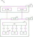
Fig. 2 is an exemplary logical architecture depicting a distributed Radio Access Network (RAN)200 that may be implemented in the wireless communication system shown in fig. 1. The 5G access node 206 may include an Access Node Controller (ANC) 202. The ANC may be a Central Unit (CU) of the distributed RAN 200. The backhaul interface for the next generation core network (NG-CN)204 may terminate at the ANC. The backhaul interface for the neighboring next generation access node (NG-AN) may terminate at the ANC. The ANC may include one or more TRPs 208 (which may also be referred to as a BS, NR BS, node B, 5G NB, AP, gNB, or some other terminology). As described above, TRP may be used interchangeably with "cell".
The local architecture 200 may be used to depict a trip definition. The architecture may be specified to support fronthaul (fronthaul) solutions that span different deployment types. For example, the architecture may be based on transmit network capabilities (e.g., bandwidth, latency, and/or jitter).
The architecture may share features and/or components with LTE. According to some aspects, the next generation AN (NG-AN)210 may support dual connectivity with NRs. NG-ANs may share a common fronthaul for LTE and NR.
This architecture may enable cooperation between TRPs 208. For example, cooperation may be pre-set among and/or across TRPs via ANC 202. According to some aspects, the inter-TRP interface may not be required/present.
According to some aspects, there may be dynamic configuration of separate logic functions in the architecture 200. As described in further detail with reference to fig. 5, a Radio Resource Control (RRC) layer, a Packet Data Convergence Protocol (PDCP) layer, a Radio Link Control (RLC) layer, a Medium Access Control (MAC) layer, and a Physical (PHY) layer may be adaptively disposed at the DU or CU (e.g., TRP or ANC, respectively). According to certain aspects, a BS may include a Central Unit (CU) (e.g., ANC 202) and/or one or more distributed units (e.g., one or more TRPs 208).
Fig. 3 illustrates an exemplary physical architecture of a distributed RAN 300, in accordance with aspects of the present disclosure. A centralized core network unit (C-CU)302 may possess core network functionality. The C-CU can be deployed in a centralized mode. The C-CU functions may be offloaded (e.g., to Advanced Wireless Services (AWS)) in an effort to handle peak capacity.
A centralized RAN unit (C-RU)304 may possess one or more ANC functions. Alternatively, the C-RU may locally own the core network functions. The C-RU may have a distributed deployment. The C-RU may be closer to the network edge.
Fig. 4 depicts exemplary components of BS 110 and UE 120 shown in fig. 1 that may be used to implement aspects of the present disclosure. As described above, the BS may include TRP. One or more components in BS 110 and UE 120 may be used to implement aspects of the present disclosure. For example, antennas 452, Tx/Rx 222, processors 466, 458, 464, and/or controller/processor 480 of UE 120, and/or antennas 434, processors 460, 420, 438, and/or controller/processor 440 of BS 110 may be used to perform the operations described herein and illustrated with reference to fig. 12 and 13.
Fig. 4 shows a block diagram of a design of BS 110 and UE 120, where BS 110 and UE 120 may be one of the BSs in fig. 1 and one of the UEs in fig. 1. For the restricted association scenario, the base station 110 may be the macro BS 110c in fig. 1 and the UE 120 may be the UE 120 y. The base station 110 may also be some other type of base station. Base station 110 may be equipped with antennas 434a through 434t and UE 120 may be equipped with antennas 452a through 452 r.
At base station 110, a transmit processor 420 may receive data from a data source 412 and control information from a controller/processor 440. The control information may be for a Physical Broadcast Channel (PBCH), a Physical Control Format Indicator Channel (PCFICH), a physical hybrid ARQ indicator channel (PHICH), a Physical Downlink Control Channel (PDCCH), and the like. The data may be for a Physical Downlink Shared Channel (PDSCH), or the like. Processor 420 may process (e.g., encode and symbol map) the data and control information to obtain data symbols and control symbols, respectively. Further, processor 420 may generate reference symbols, e.g., for PSS, SSS, and cell-specific reference signals. A Transmit (TX) multiple-input multiple-output (MIMO) processor 430 may perform spatial processing (e.g., precoding) on the data symbols, the control symbols, and/or the reference symbols, if applicable, and may provide output symbol streams to Modulators (MODs) 432a through 432 t. For example, TX MIMO processor 430 may perform certain aspects described herein for RS multiplexing. Each modulator 432 may process a respective output symbol stream (e.g., for OFDM, etc.) to obtain an output sample stream. Each modulator 432 may further process (e.g., convert to analog, amplify, filter, and upconvert) the output sample stream to obtain a downlink signal. Downlink signals from modulators 432a through 432t may be transmitted via antennas 434a through 434t, respectively.
At UE 120, antennas 452a through 452r may receive downlink signals from base station 110 and provide received signals to demodulators (DEMODs) 454a through 454r, respectively. Each demodulator 454 may condition (e.g., filter, amplify, downconvert, and digitize) a respective received signal to obtain input samples. Each demodulator 454 may further process the input samples (e.g., for OFDM, etc.) to obtain received symbols. A MIMO detector 456 may obtain received symbols from all demodulators 454a through 454r, perform MIMO detection on the received symbols (if any), and provide detected symbols. For example, MIMO detector 456 may provide detection for RSs transmitted using the techniques described herein. A receive processor 458 may process (e.g., demodulate, deinterleave, and decode) the detected symbols, provide decoded data for the UE 120 to a data sink 460, and provide decoded control information to a controller/processor 480. According to one or more scenarios, the CoMP aspects may include providing antennas and some Tx/Rx functionality such that they are located in a distributed unit. For example, some Tx/Rx processing may be performed in a central unit, while other processing may be performed in distributed units. For example, BS modulator/demodulator 432 may be in a distributed unit in accordance with one or more aspects as illustrated in the figures.
On the uplink, at UE 120, a transmit processor 464 may receive data from a data source 462 (e.g., for a Physical Uplink Shared Channel (PUSCH)), receive control information from a controller/processor 480 (e.g., for a Physical Uplink Control Channel (PUCCH)), and process the data and control information. The transmit processor 464 may also generate reference symbols for a reference signal. The symbols from the transmit processor 464 may be precoded by a TX MIMO processor 466 if applicable, further processed by the demodulators 454a through 454r (e.g., for SC-FDM, etc.), and transmitted to the base station 110. At BS 110, the uplink signals from UE 120 may be received by antennas 434, processed by modulators 432, detected by a MIMO detector 436 (if any), and further processed by a receive processor 438 to obtain decoded data and control information transmitted by UE 120. The receive processor 438 may provide the decoded data to a data sink 439 and the decoded control information to the controller/processor 440.
Controllers/ processors 440 and 480 may direct the operation at base station 110 and UE 120, respectively. For example, processor 440 and/or other processors and modules at base station 110 may perform or direct the processing for the described techniques. Processor 480 and/or other processors and modules at UE 120 may also perform or direct the processing for the techniques described herein. Memories 442 and 482 may store data and program codes for BS 110 and UE 120, respectively. A scheduler 444 may schedule UEs for data transmission on the downlink and/or uplink.
Fig. 5 illustrates a diagram 500 for implementing an example of a communication protocol stack, in accordance with an aspect of the present disclosure. The illustrated communication protocol stack may be implemented by a device operating in a 5G system (e.g., a system supporting uplink-based mobility). Diagram 500 depicts a communication protocol stack including a Radio Resource Control (RRC) layer 510, a Packet Data Convergence Protocol (PDCP) layer 515, a Radio Link Control (RLC) layer 520, a Medium Access Control (MAC) layer 525, and a Physical (PHY) layer 530. In various examples, the layers of the protocol stack may be implemented as separate software modules, as part of a processor or ASIC, as part of a non-co-located device connected by a communications link, or various combinations thereof. For example, in a protocol stack for a network access device (e.g., AN, CU, and/or DU) or UE, a co-located and non-co-located implementation may be used.
A first option 505-a illustrates a split implementation of a protocol stack, where in this implementation the protocol stack implementation is split between a centralized network access device (e.g., ANC 202 in fig. 2) and a distributed network access device (e.g., DU 208 in fig. 2). In the first option 505-a, the RRC layer 510 and the PDCP layer 515 may be implemented by a central unit, and the RLC layer 520, the MAC layer 525, and the PHY layer 530 may be implemented by DUs. In various examples, the CU and DU may or may not be co-located. The first option 505-a is used in a macro, micro, or pico cell deployment.
A second option 505-b illustrates a unified implementation of a protocol stack, where in this implementation the protocol stack is implemented in a single network access device (e.g., Access Node (AN), new radio base station (NR BS), new radio node b (NR nb), Network Node (NN), etc.). In a second option, the RRC layer 510, PDCP layer 515, RLC layer 520, MAC layer 525, and PHY layer 530 may all be implemented by the AN. The second option 505-b is useful in femtocell deployments.
Whether the network access device implements a portion of a protocol stack or an entire protocol stack, the UE may implement the entire protocol stack (e.g., RRC layer 510, PDCP layer 515, RLC layer 520, MAC layer 525, and PHY layer 530).
Fig. 6 is a diagram 600 showing an example of a DL-centric subframe. The DL-centric subframe may include a control portion 602. The control portion 602 may be located at an initial or beginning portion of the DL-centric sub-frame. The control portion 602 may include various scheduling information and/or control information corresponding to various portions of the DL-centric sub-frame. In some configurations, the control portion 602 may be a Physical DL Control Channel (PDCCH), as indicated in fig. 6. In addition, the DL-centric sub-frame 600 may also include a DL data portion 604. The DL data portion 604 may sometimes be referred to as the payload of a DL-centric subframe. The DL data portion 604 may include communication resources for transmitting DL data from a scheduling entity (e.g., a UE or BS) to a subordinate entity (e.g., a UE). In some configurations, the DL data portion 604 may be a Physical DL Shared Channel (PDSCH).
Further, the DL-centric subframe may also include a common UL portion 606. This common UL portion 606 may sometimes be referred to as an UL burst, a common UL burst, and/or various other suitable terminology. The common UL portion 606 may include feedback information corresponding to various other portions of the DL-centric sub-frame. For example, the common UL portion 606 may include feedback information corresponding to the control portion 602. Non-limiting examples of feedback information may include ACK signals, NACK signals, HARQ indicators, and/or various other suitable types of information. The common UL portion 606 may include additional or alternative information, such as information regarding Random Access Channel (RACH) procedures, Scheduling Requests (SRs), and various other suitable types of information. As shown in fig. 6, the end of the DL data portion 604 may be separated in time from the beginning of the common UL portion 606. Such temporal separation may sometimes be referred to as a gap, a guard period, a guard interval, and/or various other suitable terms. This separation provides time for a handover from DL communications (e.g., a receiving operation of a subordinate entity (e.g., a UE)) to UL communications (e.g., a transmission of a subordinate entity (e.g., a UE)). It will be appreciated by those of ordinary skill in the art that the foregoing aspects are merely one example of a DL-centric subframe and that alternative structures having similar features may exist without departing from the aspects described herein.
Fig. 7 is a diagram 700 illustrating an example of a UL-centric subframe. The UL-centric sub-frame may include a control portion 702. The control portion 702 may be located at an initial or beginning portion of the UL-centric sub-frame. The control portion 702 in fig. 7 may be similar to the control portion 702 described above with reference to fig. 6. In addition, the UL-centric sub-frame may also include a UL data portion 704. The UL data portion 704 may sometimes be referred to as the payload of a UL-centric subframe. The UL data portion may refer to a communication resource for transmitting UL data from a subordinate entity (e.g., a UE) to a scheduling entity (e.g., a UE or a BS). In some configurations, control portion 702 may be a Physical DL Control Channel (PDCCH).
As shown in fig. 7, the end of control portion 702 may be separated in time from the beginning of UL data portion 704. Such temporal separation may sometimes be referred to as a gap, a guard period, a guard interval, and/or various other suitable terms. This separation provides time for a handover from DL communication (e.g., a receive operation of the scheduling entity) to UL communication (e.g., a transmission of the scheduling entity). Further, the UL-centric subframe may also include a common UL portion 706. Common UL portion 706 in fig. 7 may be similar to common UL portion 706 described above with reference to fig. 7. Common UL portion 706 may additionally or alternatively include information regarding Channel Quality Indicators (CQIs), Sounding Reference Signals (SRS), and various other suitable types of information. It will be appreciated by those of ordinary skill in the art that the foregoing aspects are merely one example of a UL-centric sub-frame and that alternative structures having similar features may exist without departing from the aspects described herein.
In some environments, two or more subordinate entities (e.g., UEs) may communicate with each other using sidelink (sidelink) signals. Real-world applications of such sidelink communications may include public safety, proximity services, UE-to-network relays, vehicle-to-vehicle (V2V) communications, internet of everything (IoE) communications, IoT communications, mission critical grids, and/or various other suitable applications. In general, a sidelink signal may refer to a signal transmitted from one subordinate entity (e.g., UE1) to another subordinate entity (e.g., UE2) without relaying communications through the scheduling entity (e.g., UE or BS), even though the scheduling entity may be used for scheduling and/or control purposes. In some examples, the sidelink signals may be transmitted using licensed spectrum (unlike wireless local area networks, where WLANs typically use unlicensed spectrum).
The UE may operate in various radio resource configurations, including configurations associated with transmitting pilots using a dedicated set of resources (e.g., a Radio Resource Control (RRC) dedicated state, etc.), or configurations associated with transmitting pilots using a common set of resources (e.g., an RRC common state, etc.). When operating in the RRC dedicated state, the UE may select a dedicated set of resources to transmit pilot signals to the network. When operating in the RRC common state, the UE may select a common set of resources to transmit pilot signals to the network. In either case, the pilot signal transmitted by the UE may be received by one or more network access devices (e.g., AN or DU or portions thereof). Each recipient network access device may be configured to: pilot signals transmitted on a common set of resources are received and measured, and pilot signals transmitted on a dedicated set of resources assigned to the UE are also received and measured, wherein the network access device is a member of a network access device monitoring set for the UE. One or more of the CUs to which the receiving network access device or the receiving network access device sends measurements of pilot signals may use these measurements to identify a serving cell for the UE or initiate a change of serving cell for one or more of these UEs.
Exemplary reliable delivery of System information
In current wireless network deployments (e.g., LTE), system information providing system configuration parameters for a cell may be grouped into a plurality of System Information Blocks (SIBs) and periodically broadcast by an eNB. These broadcasted schedules may be included in a reduced size information block, referred to as a minimum system information message (miniSI), which may also be broadcasted periodically. In these systems, a new UE of a cell first obtains system information before being able to connect to the cell.
One potential drawback to this current design is that this broadcasting of system information may not be adaptive, which may result in a waste of system resources. For example, if there are no UEs in the cell that need the system information, but SIBs are still broadcast, these transmissions will be wasted. For this reason, it is desirable to keep the time of SIB broadcasting too short, but thereby may increase the system overhead. One potential drawback of this feature is: it may increase the delay of a UE that is obtaining system information for connecting to a cell. This increased delay is undesirable, especially in use cases where the UE attempts to connect to a new cell as soon as possible.
However, aspects of the present disclosure provide a solution to address this drawback by providing system information on demand. As described in further detail below, with this on-demand approach, SIBs may not be transmitted unless one or more UEs request them. This on-demand manner of reliably transmitting SIBs to the UE is beneficial, particularly if the UE is not already connected to the network.
Fig. 8 illustrates example operations 800 for wireless communications, in accordance with aspects of the present disclosure. The operations 800 may be performed by, for example, a UE to request transmission of SIBs on demand.
In some cases, the time period corresponds to: a number of attempts to receive the SI configured based on transmitting an expected instance of the SI in response to the first indication. In addition, reception signaling indicating the number of attempts may also be provided. In one or more cases, if the second indication is an acknowledgement of receipt of the requested SI, the second indication may be transmitted as a positive Acknowledgement (ACK) on a Physical Uplink Control Channel (PUCCH) or a designated RACH transmission. In some cases, the first indication may be sent via a designated Random Access Channel (RACH) transmission. In some cases, another operation that may be provided includes: signaling indicating when the requested SI is to be transmitted is received in a broadcast message.
Fig. 9 illustrates example operations 900 for wireless communications in accordance with aspects of the present disclosure. The operations 900 may be performed by, for example, a base station to transmit SIBs to UEs as needed (e.g., UEs performing the operations 800 described above).
In some cases, the time period may correspond to a configured number of transmissions of the SI. In some cases, these transmissions occur in pre-scheduled subframes. In some cases, an operation of sending signaling indicating the number of attempts may be included. In some cases, the following operations may be included: initializing a counter using the configured number of transmissions; and decrementing the counter at each SI transmission, wherein the decision whether to continue to transmit the SI is based on the counter.
In some cases, the deciding operation may further include: if the counter reaches zero, transmission of the SI is stopped. In some cases, the deciding operation may include: deciding to stop transmission of the SI before a counter reaches zero if each of the one or more UEs has positively acknowledged receipt of the requested SI. Further, the operations may further include: the timer is re-initialized if the network entity receives a Negative Acknowledgement (NACK) from at least one of the one or more UEs that the requested SI has not been received. In some cases, the second indication may be sent via at least one of a designated Random Access Channel (RACH) transmission or a Physical Uplink Control Channel (PUCCH) transmission.
According to the on-demand approach described herein, when a UE wants to receive ("download") a SIB, the UE sends a request to the gNB. In some cases, the request may include information about which SIB is requested. In some cases, the request may also include an Identifier (ID) of the UE, which may help the gNB track which UEs have requested (and subsequently acknowledged) the SIBs.
When the on-demand request is received by the gNB, the gNB can transmit the requested SIB. There are a number of options for determining when to send the SIB. According to a first option, once the request is received and processed by the gNB, the gNB can transmit the SIB. In this way, the delay between the time the UE sends the request and the time the gNB first sends the SIB may be fixed (its UE is known). As a result, the UE knows when to expect the first transmission of its requested SIB. This knowledge may allow the UE to determine, for example, when to send a Negative Acknowledgement (NACK) or request retransmission of the requested SIB.
According to a second option, the gNB may broadcast the SIBs in pre-scheduled subframes (only when requested). For example, these pre-scheduled subframes may include: subframe window where SIB transmission instances can occur on demand. For example, the window may cover a single instance of a single subframe or a range of subframes for an unlicensed spectrum for which the medium may not be guaranteed to be available in a particular subframe.
Typically, pre-scheduled subframes are used, and the SIB is not broadcast if a request for the SIB is not received before the scheduled time of the SIB. Otherwise, the gNB may respond to all received requests only at the next scheduled time for that SIB. The broadcast schedule for each SIB (of a different type) may be announced in the miniSI. Knowing this schedule, if the UE requests the SIB, the UE can calculate when the UE can expect to receive the SIB.
In some cases, the gNB may track a group of UEs that have sent the request. For example, as described below, the gNB may stop transmitting the SIB if all UEs requesting the SIB have acknowledged receipt of the SIB (or no UEs have negatively acknowledged receipt).
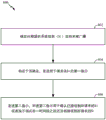
After sending the request, the UE attempts to receive the SIB at its expected transmission time, as described above. There are many options that can help ensure that the gbb successfully receives the SIB. According to one option, as shown in fig. 10, on the side of the gNB, after the first broadcast of the SIB, the gNB starts a counter with an initial value Nc at 1010, broadcasting the SIB repeatedly. After each broadcast, the counter may be decremented by 1. When the counter reaches zero, the gNB stops broadcasting the SIB. Nc may be announced in miniSI and thus the UE may know. In some cases, the gNB may reset (re-initialize) the retransmission counter to Nc as long as the gNB receives a NACK (e.g., from any UE requesting the SIB). On the UE side, if the UE successfully receives the SIB, the UE may not need to take further action. On the other hand, if the UE does not receive the SIB after the consecutive number of attempts Nc, the UE may send a Negative Acknowledgement (NACK) to the gNB. For example, the NACK may be sent via a specific Random Access Channel (RACH) preamble or message, or via a Physical Uplink Control Channel (PUCCH). This process may be repeated until the UE successfully receives the SIB.
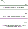
According to another option shown in fig. 11, if the UE successfully receives the SIB, the UE sends an ACK to the gNB, completing the UE-side on-demand transfer procedure. For example, the ACK may be transmitted via a specific Random Access Channel (RACH) preamble or message or via a Physical Uplink Control Channel (PUCCH). This process may be repeated until the UE successfully receives the SIB. Otherwise, the UE may continue to try and receive the SIB again at the next expected transmission time of the SIB. On the network side, the gNB may continue to broadcast SIBs. Meanwhile, the gNB may track the set of UEs that have sent the ACK. If the gNB has received ACKs from all UEs that sent the request, the gNB can stop broadcasting the SIB.
In some cases, there may be collisions between UEs that simultaneously send ACKs over the PUCCH. This may result in the gNB continuously transmitting SIBs if the gNB fails to detect a collision and the UE transmits an ACK only once. To avoid this, the gNB may stop broadcasting after Nmax repeats, even if the gNB does not receive ACKs from all UEs. This Nmax may be announced in the miniSI so that the UE should resend its request when it does not receive the SIB after the number of Nmax attempts.
As noted above, there are different implementation options for the messages described herein (e.g., request for on-demand SIBs, NACK, and ACK). For practical implementation, for any given deployment, the network (operator) may choose to use any combination of the options described herein, along with any of the above described transmission options, to achieve reliable transmission of SIBs. In some cases, this specific configuration may be announced in the miniSI so that the UEs know how to perform their procedures accordingly.
In some cases, for on-demand SIB requests, the UE may send a special preamble on a Random Access Channel (RACH). Further, the request for the SIB may be sent in a designated RACH slot for the SIB (e.g., slot 1 for SIB3, slot 5 for SIB4, etc.) so that when the particular preamble is received by the gNB, the gNB knows which SIB is being requested. In some cases, the request may be sent in a so-called message 3 (assuming a conventional two-step or four-step RACH procedure). In these cases, the UE may indicate in message 3 which SIB the UE is requesting.
In some cases, the UE may signal a NACK by transmitting a special RACH preamble. This special preamble may be transmitted in any RACH slot since the gNB does not need to know which UE sent the NACK (if any UE sent the NACK, its counter may be reset). In some cases, the NACK may be sent using the same message as the original request (e.g., the NACK effectively serves another request for the on-demand SIB). In use cases where strict timing advance is not required, special PUCCH resources may be configured for the purpose of sending a NACK to the gNB. The resource and its time period may be announced in the miniSI. The corresponding PUCCH format may be specified to include information on which SIB the NACK is intended for.
In some cases, the UE may signal an ACK in message 3 in a conventional two-or four-step RACH procedure. The UE may indicate that it is an ACK in message 3. As described above, the ACK may also include the UE ID and information about which SIB the ACK is for. In use cases where strict timing advance is not required, special PUCCH resources may be configured for the purpose of sending ACKs to the gNB. The resource and its time period may be announced in the miniSI. The corresponding PUCCH format may be specified to include the UE ID and information on which SIB the ACK is intended. As mentioned above, since collisions may occur when there are multiple UEs using the PUCCH resource simultaneously, the additional steps described above may be taken when using this option (to avoid collisions or at least to take collisions into account).
The methods disclosed herein comprise one or more steps or actions for achieving the described method. The method steps and/or actions may be interchanged with one another without departing from the scope of the invention. In other words, unless a specific order of steps or actions is specified, the order and/or use of specific steps and/or actions may be modified without departing from the scope of the invention.
As used herein, a phrase referring to "at least one of a list of items refers to any combination of these items, including a single member. For example, "at least one of a, b, or c" is intended to cover: a. b, c, a-b, a-c, b-c, and a-b-c, and any combination having a plurality of the same elements (e.g., a-a-a, a-a-b, a-a-c, a-b-b, a-c-c, b-b-b, b-b-c, c-c, and c-c-c, or any other ordering of a, b, and c). As used herein (which includes the claims), when the term "and/or" is used in a list of two or more items, it means that any one of the listed items is used, or any combination of two or more of the listed items is used. For example, if a complex is described as containing component A, B and/or C, the complex can contain only A; only B is contained; only C is contained; a combination of A and B; a combination of A and C; a combination of B and C; or a combination of A, B and C.
As used herein, the term "determining" encompasses a wide variety of actions. For example, "determining" can include calculating, computing, processing, deriving, studying, querying (e.g., a look-up table, database, or other data structure), ascertaining, and the like. Further, "determining" may also include receiving (e.g., receiving information), accessing (e.g., accessing data in a memory), and so forth. Further, "determining" may also include resolving, selecting, establishing, and the like.
The foregoing has outlined various aspects in order that those skilled in the art may be able to practice the various aspects described herein. Various modifications to these aspects will be readily apparent to those skilled in the art, and the generic principles defined herein may be applied to other aspects. Thus, the present invention is not limited to the aspects shown herein, but is to be accorded the full scope consistent with the disclosure, wherein reference to an element in the singular is not intended to mean "one and only one" unless specifically so stated, but rather "one or more. For example, the articles "a" and "an" as used in this application and the appended claims should generally be construed to mean "one or more" unless specified otherwise or clear from context to be directed to a singular form. The term "some" refers to one or more, unless specifically stated otherwise. Furthermore, the term "or" is intended to mean an inclusive "or" rather than an exclusive "or". That is, for example, the phrase "X employs A or B" is intended to mean any of the natural inclusive permutations, unless specified otherwise or clear from the context. That is, for example, any one of the following statements satisfies the phrase "X employs a or B": x is A; b is used as X; or X employs A and B. All structural and functional equivalents to the elements of the various aspects described throughout this disclosure that are known or later come to be known to those of ordinary skill in the art are expressly incorporated herein by reference and are intended to be encompassed by the claims. Moreover, nothing disclosed herein is intended to be dedicated to the public regardless of whether such disclosure is explicitly recited in the claims. Furthermore, no element of any claim should be construed in accordance with 35u.s.c. § 112 sixth clause, unless the element is explicitly recited in the language "functional module" or in a method claim is recited in the language "functional step".
The various operations of the methods described above may be performed by any suitable means capable of performing the corresponding functions. These units may include various hardware and/or software components and/or modules, including but not limited to: a circuit, an Application Specific Integrated Circuit (ASIC), or a processor. Generally, where operations are shown in the figures, the operations may have correspondingly paired functional module components that are similarly numbered. For example, the operation 800 illustrated in fig. 8 and the operation 900 illustrated in fig. 9 correspond to the unit 800A illustrated in fig. 8A, the unit 900A illustrated in fig. 9A, respectively.
For example, the transmitting unit (or transmitting unit) and/or the receiving unit may comprise one or more of the following: a transmit processor 420, a TX MIMO processor 430, a receive processor 438, or antennas 434 of the base station 110 and/or a transmit processor 464, a TX MIMO processor 466, a receive processor 458, or antennas 452 of the user equipment 120. Further, the determining unit, the signaling unit, the indicating unit, the monitoring unit, the deciding unit, the initializing unit, the decrementing unit and/or the unit for initializing may comprise one or more processors, e.g. the controller/processor 440 of the base station 110 and/or the controller/processor 480 of the user equipment 120. The various illustrative logical blocks, modules, and circuits described in connection with the disclosure herein may be implemented or performed with a general purpose processor, a Digital Signal Processor (DSP), an Application Specific Integrated Circuit (ASIC), a Field Programmable Gate Array (FPGA) or other Programmable Logic Device (PLD), discrete gate or transistor logic, discrete hardware components, or any combination thereof designed to perform the functions described herein. A general-purpose processor may be a microprocessor, but in the alternative, the processor may be any commercially available processor, controller, microcontroller or state machine. A processor may also be implemented as a combination of computing devices, e.g., a combination of a DSP and a microprocessor, a plurality of microprocessors, one or more microprocessors in conjunction with a DSP core, or any other such configuration.
When implemented in hardware, an exemplary hardware configuration may include a processing system in the wireless node. The processing system may be implemented using a bus architecture. The bus may include any number of interconnecting buses and bridges depending on the specific application of the processing system and the overall design constraints. The bus may link together various circuits including the processor, the machine-readable medium, and the bus interface. A bus interface may be used to connect a network adapter or the like to the processing system via the bus. Network adapters may be used to implement signal processing functions at the physical layer. In the case of a user terminal 120 (see fig. 1), a user interface (e.g., keyboard, display, mouse, joystick, etc.) may also be connected to the bus. The bus also links various other circuits such as clock sources, peripherals, voltage regulators, power management circuits, and the like, which are well known in the art, and therefore, are not described any further. A processor may be implemented using one or more general-purpose processors and/or special-purpose processors. Examples include microprocessors, microcontrollers, DSP processors, and other circuits capable of executing software. Those skilled in the art will recognize how best to implement the described functionality of the processing system, depending on the particular application and the overall design constraints imposed on the overall system.
When implemented in software, the functions may be stored on or transmitted over as one or more instructions or code on a non-transitory computer-readable medium. Software should be construed broadly to mean instructions, data, or any combination thereof, etc., whether referred to as software, firmware, middleware, microcode, hardware description language, or other terminology. Computer-readable media includes both computer storage media and communication media including any medium that facilitates transfer of a computer program from one place to another. The processor may be responsible for managing the bus and general processing, including the execution of software stored on a machine-readable storage medium. A computer readable storage medium may be coupled to the processor such that the processor can read information from, and write information to, the storage medium. In the alternative, the storage medium may be integral to the processor. By way of example, the machine-readable medium may include a transmission line, a carrier waveform modulated with data, and/or a computer-readable storage medium separate from the wireless node and having instructions stored thereon, all of which may be accessed by the processor through a bus interface. Alternatively or additionally, the machine-readable medium or any portion thereof may be integral to the processor, for example, with a cache and/or a general register file. Examples of a machine-readable storage medium may include, by way of example, RAM (random access memory), flash memory, phase change memory, ROM (read only memory), PROM (programmable read only memory), EPROM (erasable programmable read only memory), EEPROM (electrically erasable programmable read only memory), registers, a magnetic disk, an optical disk, a hard disk, or any other suitable storage medium, or any combination thereof. The machine-readable medium may be embodied by a computer program product.
A software module may comprise a single instruction, or many instructions, and may be distributed over several different code segments, among different programs, and across multiple storage media. The computer readable medium may include a plurality of software modules. These software modules include instructions that, when executed by a device such as a processor, cause the processing system to perform various functions. The software modules may include a transmission module and a reception module. Each software module may be located in a single memory device or may be distributed across multiple memory devices. For example, when a triggering event occurs, a software module may be loaded from a hard disk into RAM. During execution of the software module, the processor may load some of these instructions into the cache to increase access speed. Subsequently, one or more cache lines may be loaded into a general register file for execution by the processor. When referring to the functionality of the following software module, it should be understood that the functionality is implemented by the processor when executing instructions from the software module.
Further, any connection is properly termed a computer-readable medium. For example, if the software is transmitted from a website, server, or other remote source using a coaxial cable, fiber optic cable, twisted pair, Digital Subscriber Line (DSL), or wireless technologies such as Infrared (IR), radio, and microwave, then the coaxial cable, fiber optic cable, twisted pair, DSL, or wireless technologies such as infrared, radio, and microwave are included in the definition of medium. Disk and disc, as used herein, includes Compact Disc (CD), laser disc, optical disc, Digital Versatile Disc (DVD), floppy disk and optical disks, where disks usually reproduce data magnetically, while lasers reproduce data optically. Thus, in some aspects, computer-readable media may comprise non-transitory computer-readable media (e.g., tangible media). Further, for other aspects, the computer readable medium may comprise a transitory computer readable medium (e.g., a signal). Combinations of the above should also be included within the scope of computer-readable media.
Accordingly, certain aspects may comprise a computer program product for performing the operations presented herein. For example, the computer-program product may include a computer-readable medium having instructions (and/or encoded thereon) executable by one or more processors to perform the operations described herein. For example, instructions for performing the operations described herein and illustrated in the figures.
Further, it is to be appreciated that modules and/or other suitable means for performing the methods and techniques described herein can be downloaded and/or obtained by a user terminal and/or base station as needed. Such apparatus may be coupled to a server, for example, to facilitate the implementation of means for communicating to perform the methods described herein. Alternatively, various methods described herein can be provided via a storage unit (e.g., RAM, ROM, a physical storage medium such as a Compact Disc (CD) or floppy disk, etc.), such that the various methods are available when the storage unit is coupled to or provided to the device by the user terminal and/or base station. Moreover, any other suitable technique for providing the methods and techniques described herein to a device may also be used.
It should be understood that the invention is not limited to the precise arrangements and components shown above. Various modifications, changes, and variations may be made in the arrangement, operation, and details of the methods and apparatus described above without departing from the scope of the invention.
Claims (19)
1. A method of wireless communication for a User Equipment (UE), comprising:
determining that System Information (SI) desired by the UE is not currently broadcast;
in response to the determination, sending a first indication to request the SI; and
in response to the UE not receiving the requested SI for a time period during which the UE refrains from transmitting another indication to request the SI, transmitting a second indication indicating that the UE has not received the requested SI after the time period, wherein the time period corresponds to: a number of attempts to receive the requested SI during the time period configured based on a number of instances of transmission of the requested SI configured during the time period in response to the first indication.
2. The method of claim 1, wherein the first indication is transmitted further in response to determining that the requested SI is available on demand.
3. The method of claim 1, wherein the expected plurality of instances occur in pre-scheduled subframes.
4. The method of claim 1, further comprising:
receiving, signaling, and indicating the configured number of the plurality of attempts.
5. The method of claim 1, wherein the first indication is transmitted via a designated Random Access Channel (RACH) transmission.
6. The method of claim 1, wherein the second indication is transmitted in the same manner as the first indication.
7. The method of claim 1, wherein:
transmitting the second indication as a Negative Acknowledgement (NACK) on a Physical Uplink Control Channel (PUCCH) or a designated RACH transmission to request retransmission of the requested SI.
8. The method of claim 1, further comprising: in response to the UE receiving the requested SI, sending a third indication confirming receipt of the requested SI, wherein:
the third indication is transmitted as a positive Acknowledgement (ACK).
9. The method of claim 1, further comprising:
in a broadcast message, signaling is received indicating when the requested SI will be transmitted.
10. A method of wireless communication for a network entity, comprising:
receiving a first indication from one or more User Equipments (UEs) as a request for System Information (SI);
transmitting the requested SI in response to the first indication;
monitoring a second indication for determining that at least one of the one or more UEs has not received the requested SI after a time period during which the at least one of the one or more UEs refrains from transmitting another indication for requesting the SI, wherein the time period corresponds to a configured number of transmissions of the requested SI during the time period; and
deciding whether to continue sending the requested SI based on the monitoring.
11. The method of claim 10, wherein the transmission of the configured number of the plurality of transmissions occurs in a pre-scheduled subframe.
12. The method of claim 10, further comprising:
signaling is sent indicating a number of attempts to send the requested SI.
13. The method of claim 10, further comprising:
initializing a counter using the configured number of the plurality of transmissions; and
decrementing the counter at each SI transmission, wherein the decision whether to continue sending the requested SI is based on the counter.
14. The method of claim 13, wherein the deciding comprises: deciding to stop transmission of the requested SI if the counter reaches zero.
15. The method of claim 14, wherein the deciding comprises: deciding to stop transmission of the requested SI before the counter reaches zero if each of the one or more UEs has positively acknowledged receipt of the requested SI.
16. The method of claim 13, further comprising:
re-initializing a timer if the network entity receives a Negative Acknowledgement (NACK) from at least one of the one or more UEs that the requested SI has not been received.
17. The method of claim 10, wherein the first indication is received via a designated Random Access Channel (RACH) transmission.
18. The method of claim 10, wherein the second indication is transmitted via at least one of a designated Random Access Channel (RACH) transmission or a Physical Uplink Control Channel (PUCCH) transmission.
19. The method of claim 10, further comprising:
indicating in the broadcast message when the requested SI is to be transmitted.
Applications Claiming Priority (5)
| Application Number | Priority Date | Filing Date | Title |
|---|---|---|---|
| US201762480290P | 2017-03-31 | 2017-03-31 | |
| US62/480,290 | 2017-03-31 | ||
| US15/905,425 | 2018-02-26 | ||
| US15/905,425 US20180288748A1 (en) | 2017-03-31 | 2018-02-26 | Reliable delivery of system information |
| PCT/US2018/019872 WO2018182900A1 (en) | 2017-03-31 | 2018-02-27 | Reliable delivery of system information |
Publications (2)
| Publication Number | Publication Date |
|---|---|
| CN110463277A CN110463277A (en) | 2019-11-15 |
| CN110463277B true CN110463277B (en) | 2021-12-03 |
Family
ID=63671264
Family Applications (1)
| Application Number | Title | Priority Date | Filing Date |
|---|---|---|---|
| CN201880022294.4A Active CN110463277B (en) | 2017-03-31 | 2018-02-27 | Reliable transfer of system information |
Country Status (9)
| Country | Link |
|---|---|
| US (1) | US20180288748A1 (en) |
| EP (1) | EP3603205A1 (en) |
| JP (1) | JP7110227B2 (en) |
| KR (1) | KR20190132678A (en) |
| CN (1) | CN110463277B (en) |
| BR (1) | BR112019019913A2 (en) |
| SG (1) | SG11201907575XA (en) |
| TW (1) | TWI767996B (en) |
| WO (1) | WO2018182900A1 (en) |
Families Citing this family (7)
| Publication number | Priority date | Publication date | Assignee | Title |
|---|---|---|---|---|
| CN108476385B (en) * | 2017-05-12 | 2021-11-02 | 北京小米移动软件有限公司 | Method, device, user equipment and base station for receiving and sending system messages |
| WO2019201442A1 (en) * | 2018-04-19 | 2019-10-24 | Huawei Technologies Co., Ltd. | Transmitting device and receiving device for wireless communications |
| US10667194B2 (en) * | 2018-09-24 | 2020-05-26 | Qualcomm Incorporated | Threshold-based system information on demand |
| US11653269B2 (en) * | 2019-08-06 | 2023-05-16 | Qualcomm Incorporated | Recommended bit rate and recommended bit rate query for uplink and downlink streaming |
| WO2021046816A1 (en) * | 2019-09-12 | 2021-03-18 | 华为技术有限公司 | Communication method and apparatus |
| CN113260018B (en) * | 2020-02-07 | 2023-01-24 | 维沃移动通信有限公司 | System information transmission method, terminal equipment and network equipment |
| US20220104109A1 (en) * | 2020-09-28 | 2022-03-31 | Qualcomm Incorporated | Techniques for adaptatively requesting on-demand system information |
Citations (1)
| Publication number | Priority date | Publication date | Assignee | Title |
|---|---|---|---|---|
| CN105637842A (en) * | 2013-09-20 | 2016-06-01 | 甲骨文国际公司 | Techniques for reliable messaging for an intermediary in a network communication environment |
Family Cites Families (19)
| Publication number | Priority date | Publication date | Assignee | Title |
|---|---|---|---|---|
| JPH08274667A (en) * | 1995-03-30 | 1996-10-18 | Sanyo Electric Co Ltd | Fm receiver and signal processor used for this receiver |
| KR101221901B1 (en) * | 2006-06-22 | 2013-01-15 | 엘지전자 주식회사 | Data retransmitting method in multiple subcarrier system and its transceiver implementation |
| GB2466191B (en) * | 2008-12-09 | 2010-12-29 | Ipwireless Inc | Communication system,apparatus and methods for providing and acquiring a system information message |
| CN102075949B (en) * | 2010-12-22 | 2013-03-20 | 大唐移动通信设备有限公司 | Carrier aggregation (CA) technology-based data transmission method and device |
| CN104782185A (en) * | 2012-09-13 | 2015-07-15 | Lg电子株式会社 | Operating method for acquiring system information in wireless communication system, and apparatus for supporting same |
| US10524283B2 (en) * | 2013-09-25 | 2019-12-31 | Sony Corporation | Telecommunications apparatus and methods |
| US10903943B2 (en) * | 2014-06-13 | 2021-01-26 | Apple Inc. | Enhanced LTE UL HARQ feedback indication for power saving and range improvement |
| US10616822B2 (en) * | 2015-02-10 | 2020-04-07 | Qualcomm Incorporated | System information updating |
| US10200920B2 (en) * | 2015-02-10 | 2019-02-05 | Qualcomm Incorporated | On-demand system information |
| WO2017123144A1 (en) * | 2016-01-13 | 2017-07-20 | Telefonaktiebolaget Lm Ericsson (Publ) | Configuration of autonomous gaps based on repetition level in enhanced coverage |
| EP3454620B1 (en) * | 2016-05-04 | 2020-12-09 | LG Electronics Inc. -1- | Method and apparatus for receiving osi block in wireless communication system |
| EP4216612A1 (en) * | 2016-11-04 | 2023-07-26 | Samsung Electronics Co., Ltd. | Method and user equipment for provisioning minimum system information in wireless communication system |
| US20180167918A1 (en) * | 2016-12-13 | 2018-06-14 | Sharp Laboratories Of America, Inc. | Wireless telecommunications methods and apparatus comprising advance notification of change of system information |
| WO2018143735A1 (en) * | 2017-02-02 | 2018-08-09 | Samsung Electronics Co., Ltd. | Method and apparatus for transmitting and receiving system information |
| US10327264B2 (en) * | 2017-03-20 | 2019-06-18 | Motorola Mobility Llc | Determining a request for system information |
| TWI666948B (en) * | 2017-03-24 | 2019-07-21 | 聯發科技股份有限公司 | Apparatus and methods for on-demand system information request procedure |
| KR102508783B1 (en) * | 2017-05-03 | 2023-03-13 | 모토로라 모빌리티 엘엘씨 | Feedback on system information requests |
| US20180323908A1 (en) * | 2017-05-05 | 2018-11-08 | Chie-Ming Chou | System information transmission method and wireless communication system |
| CN110622448B (en) * | 2017-05-24 | 2022-09-09 | 摩托罗拉移动有限责任公司 | Method and apparatus for performing an action based on a number of transmissions reaching a threshold |
-
2018
- 2018-02-26 US US15/905,425 patent/US20180288748A1/en active Pending
- 2018-02-27 KR KR1020197031882A patent/KR20190132678A/en active IP Right Grant
- 2018-02-27 BR BR112019019913A patent/BR112019019913A2/en unknown
- 2018-02-27 SG SG11201907575X patent/SG11201907575XA/en unknown
- 2018-02-27 WO PCT/US2018/019872 patent/WO2018182900A1/en active Application Filing
- 2018-02-27 EP EP18711734.6A patent/EP3603205A1/en active Pending
- 2018-02-27 TW TW107106534A patent/TWI767996B/en active
- 2018-02-27 JP JP2019552963A patent/JP7110227B2/en active Active
- 2018-02-27 CN CN201880022294.4A patent/CN110463277B/en active Active
Patent Citations (1)
| Publication number | Priority date | Publication date | Assignee | Title |
|---|---|---|---|---|
| CN105637842A (en) * | 2013-09-20 | 2016-06-01 | 甲骨文国际公司 | Techniques for reliable messaging for an intermediary in a network communication environment |
Non-Patent Citations (1)
| Title |
|---|
| System Information Signalling Design in NR;Samsung;《3GPP TSG-RAN WG2 Meeting #94 R2-163371》;20160522;正文第2节 * |
Also Published As
| Publication number | Publication date |
|---|---|
| TW201842809A (en) | 2018-12-01 |
| KR20190132678A (en) | 2019-11-28 |
| BR112019019913A2 (en) | 2020-04-22 |
| EP3603205A1 (en) | 2020-02-05 |
| CN110463277A (en) | 2019-11-15 |
| JP2020512768A (en) | 2020-04-23 |
| SG11201907575XA (en) | 2019-10-30 |
| TWI767996B (en) | 2022-06-21 |
| JP7110227B2 (en) | 2022-08-01 |
| US20180288748A1 (en) | 2018-10-04 |
| WO2018182900A1 (en) | 2018-10-04 |
Similar Documents
| Publication | Publication Date | Title |
|---|---|---|
| CN110999409B (en) | Multibeam PDCCH monitoring during CDRX operation | |
| CN109804700B (en) | Multi-stage channel reservation signal for directional transmission and reception | |
| CN110612746B (en) | Configuration of remaining system information transfer windows | |
| CN111226413B (en) | Aperiodic tracking reference signal | |
| CN110463277B (en) | Reliable transfer of system information | |
| CN112514296A (en) | Coordinated transmitted feedback mode indication | |
| US11219086B2 (en) | Enhanced machine type communications quick idle transition after connection release | |
| TWI767041B (en) | Prioritized random access procedure | |
| CN110506447B (en) | Scheduling request multiplexing based on reliability and delay objectives | |
| WO2019036692A1 (en) | Uplink power control | |
| CN110546895A (en) | Method for improving wave beam of base station | |
| EP3701655A1 (en) | Implicit acknowledgment (ack) mapping | |
| EP3622761A1 (en) | Multiplexing paging signals with synchronization signals in new radio | |
| CN111316753A (en) | Radio link monitoring based on discontinuous reception mode | |
| CN110870370A (en) | Configuration of beam pair link during random access | |
| CN110892690B (en) | Uplink and downlink grants for narrowband operation | |
| WO2018200078A1 (en) | Radio link control/packet data convergence protocol window advance with holes | |
| CN110892665B (en) | Physical Uplink Control Channel (PUCCH) sequence configuration |
Legal Events
| Date | Code | Title | Description |
|---|---|---|---|
| PB01 | Publication | ||
| PB01 | Publication | ||
| SE01 | Entry into force of request for substantive examination | ||
| SE01 | Entry into force of request for substantive examination | ||
| REG | Reference to a national code |
Ref country code: HK Ref legal event code: DE Ref document number: 40016065 Country of ref document: HK |
|
| GR01 | Patent grant | ||
| GR01 | Patent grant |