Elastic transition section multi-cylinder foundation structure and construction method thereof
Technical Field
The invention relates to the technical field of foundation structures of ocean engineering, in particular to a multi-cylinder combined foundation structure and a construction method thereof.
Background
As a novel offshore wind power generation foundation, the large-scale cylindrical foundation can be built on land and installed on the sea quickly, has strong anti-overturning capability, is suitable for various foundation geology, and can make full use of the advantage of abundant offshore wind energy resources. The transition section is used as a force transmission structure of the novel offshore wind power generation foundation, and is related to whether the foundation structure can safely transmit the upper load to the foundation or not, so that the bearing capacity of the foundation is exerted to the maximum extent. Along with the increase of the water depth, the load transmitted to the top end of the transition section by the large bending moment received by the upper fan and the tower barrel is larger, a larger transition section structure is needed, and the phenomenon of stress concentration is easy to occur. However, the construction of a larger transition section needs the assistance of a large-scale machine, the requirements of reinforcing steel bars and concrete are larger, and the cost is also increased greatly.
Disclosure of Invention
The invention aims to solve the technical problems of unreasonable load transfer and complex construction and installation of the existing offshore foundation structure, and provides an elastic transition section multi-cylinder foundation structure and a construction method thereof, which skillfully and effectively transfer the load of an upper structure to a linear transition section and a concrete top plate in the construction period and the operation period and further transfer the load to a steel cylinder foundation at the lower part.
In order to solve the technical problems, the invention is realized by the following technical scheme:
an elastic transition section multi-cylinder foundation structure comprises a plurality of identical steel cylinder foundations, wherein the plurality of steel cylinder foundations are arranged in a circular shape on a horizontal plane according to a central point connecting line, and the plurality of steel cylinder foundations are welded together; the top parts of the steel cylinder foundations are commonly connected with a steel top plate, a concrete plate is arranged on the upper part of the steel top plate, a concrete transition section is arranged on the upper part of the concrete plate, the concrete transition section is of a linear thin-walled structure with a circular ring section, and the diameter of a circular ring at the bottom is larger than that of a circular ring at the top; a section of steel tower drum is arranged at the upper part of the concrete transition section, and the lower part of the steel tower drum penetrates through the concrete transition section and is in contact with the concrete slab;
the top surface of the concrete plate is provided with an outer ring beam, a middle ring beam, a first inner ring beam and a second inner ring beam; the outer ring beam is positioned at the edge of the outer side of the top surface of the concrete plate; the middle ring beam is positioned in the middle of the top surface of the concrete plate and is arranged at the lower part of the concrete transition section; the first inner ring beam is arranged on the inner side of the steel tower cylinder, and the second inner ring beam is arranged on the outer side of the steel tower cylinder; the bottom end of the steel tower is inserted between the second inner ring beam and the first inner ring beam;
the top surface of the concrete plate is uniformly provided with concrete main beams in the radial direction, and the concrete main beams extend from the second inner ring beam to the outer ring beam; concrete secondary beams are uniformly arranged on the top surface of the concrete plate in the radial direction between every two adjacent concrete main beams, and the concrete secondary beams extend from the middle ring beam to the outer ring beam;
the steel tower cylinder is in contact with the top of the concrete transition section through an elastic buffer device, and the bottom of the steel tower cylinder is in contact with the first inner ring beam and the second inner ring beam through elastic buffer devices.
Further, the number of the steel cylinder bases is 3-6; the radius of the steel cylinder foundation is 3-15m, and the height of the steel cylinder foundation is 5-15 m.
Furthermore, an upward steel rib plate is arranged on the periphery of the steel top plate, and the steel rib plate is inserted into the concrete plate and the outer ring beam.
Further, the concrete plate is consistent with the outline of the steel top plate, and the thickness of the concrete plate is 0.3-1 m.
Furthermore, circular through holes are formed in the centers of the steel top plate and the concrete slab, and the circular through holes do not intersect with projections of the steel cylinder foundation on the steel top plate and the concrete slab.
Furthermore, the concrete transition section is of an equal-thickness structure, the wall thickness of the concrete transition section is 0.5-1.5m, and prestressed steel strands are distributed in the middle of the concrete transition section.
Further, the outer edge of the outer ring beam is flush with the outer edge of the concrete slab, and the shape of the outer ring beam is consistent with the edge of the concrete slab; the width of the outer ring beam is 0.5-1.5m, and the height of the outer ring beam is 0.8-1.8 m; the middle ring beam is positioned in the middle of the top surface of the concrete plate, is annular, and has a width of 0.5-1.5m and a height of 0.8-1.8 m; the radius of the middle ring beam is 1.5-2.5 times of that of the steel tower cylinder; the outer diameter of the first inner ring beam is 0.2-1m smaller than the inner diameter of the steel tower cylinder, the width is 0.5-2.5m, and the height is 0.8-1.8 m; the inner diameter of the second inner ring beam is 0.2-1m larger than the outer diameter of the steel tower cylinder, the width of the second inner ring beam is 0.5-2.5m, and the height of the second inner ring beam is 0.8-1.8 m.
Further, the width of the concrete girder is 0.5-1.5m, and the height of the concrete girder is 0.8-1.8 m; the included angle between the adjacent concrete main beams is 60 degrees; the concrete secondary beams comprise 12-18, 2-3 concrete secondary beams are arranged between every two adjacent concrete main beams, and the included angle between the axes of the adjacent concrete secondary beams is 20-30 degrees.
Further, the elastic buffer device 12 is composed of a waterproof layer a, an oxidation resistant layer b, an elastic metal coil c, a first rubber layer d, a rubber convex layer e and a second rubber layer f in sequence, the thickness is 0.2-1m, and the height is 0.8-1.8 m.
A construction method of the elastic transition section multi-cylinder foundation structure comprises the following steps:
(1) prefabricating a plurality of steel cylinder foundations on land, arranging the plurality of steel cylinder foundations on a horizontal plane according to a central point connecting line to form a circle, welding the steel cylinder foundations and the steel top plate together, and then welding the plurality of steel cylinder foundations and the steel top plate together;
(2) taking the steel top plate as a bottom surface template of the concrete slab, binding steel bars on the steel top plate, and carrying out pouring construction on the concrete slab, the outer ring beam, the middle ring beam, the first inner ring beam, the second inner ring beam, the concrete main beam, the concrete secondary beam and the concrete transition section together;
(3) hoisting the integral structure after the pouring construction into water, checking the air tightness, mounting the steel tower drum on the concrete slab, mounting elastic buffer devices between the bottom of the steel tower drum and the first inner ring beam, between the bottom of the steel tower drum and the second inner ring beam, and between the steel tower drum and the top of the concrete transition section, mounting a machine head on the steel tower drum, and adjusting the draught of the steel drum foundation according to towing requirements;
(4) carrying out floating towing on the multi-cylinder combined foundation structure and the machine head;
(5) after the multi-cylinder combined foundation structure and the machine head are subjected to floating towing to a designated sea area, self-weight sinking is firstly carried out, and then negative pressure sinking is carried out to a designated position;
(6) and after the sinking is finished, reinforcing the soil body in the steel cylinder foundation.
The invention has the beneficial effects that:
according to the elastic transition section multi-cylinder foundation structure, a plurality of single-cylinder foundations are connected into a whole through the steel top plate and the concrete plate, so that the anti-overturning moment of the multi-cylinder reinforced concrete combined foundation structure is increased, and the stability in the transportation process is improved; the single-cylinder foundation is small in diameter, convenient to manufacture and rapid to transport, the steel cylinders are welded with one another to form a rigid whole to resist large bending moment load borne by the offshore wind turbine, the steel cylinders with small diameters are stressed in a coordinated mode under the condition of large bending moment, the rigidity is large, the deformation amount is small, buckling deformation in the sinking process can be reduced, and different negative pressures can be applied to the steel cylinders to level inclination angles generated in the sinking process. And the steel cylinders are mutually independent, so that the single steel cylinder can be stably hauled after being broken in the marine hauling process, and the influence on the basic floating transportation is small. The invention is formed by welding a plurality of steel cylinders, can design different numbers and arrangement modes of the steel cylinders according to different hydrological conditions, and is convenient and fast to construct.
According to the elastic transition section multi-cylinder foundation structure, the elastic buffer devices are arranged between the steel cylinder and the concrete transition section and between the steel cylinder and the two inner ring beams, so that a part of load can be dissipated while the upper bending moment load is effectively transmitted, and the hard contact and the crushing of concrete between the steel cylinder and a concrete structure are prevented.
According to the elastic transition section multi-cylinder foundation structure, the steel top plate, the concrete plate and the steel cylinder are connected, so that the integrity of a plurality of steel cylinder foundations is enhanced, the conditions of mutual dislocation and the like among the steel cylinder foundations in the construction process can be effectively improved, the construction quality is improved, and the excessive difference of internal force among the steel cylinder foundations is avoided, so that the non-uniform settlement of the whole multi-cylinder combined foundation structure is reduced, the sinking resistance of the plurality of steel cylinder foundations in water is reduced due to the arrangement of the middle circular holes of the steel top plate and the concrete plate, and the construction is facilitated.
The elastic transition section multi-cylinder foundation structure can realize the technology of 'onshore prefabrication-floating transportation-towing-sinking-leveling' in construction, has reliable pouring quality, does not have impact load such as piling and the like, avoids using large-scale machinery such as hoisting equipment and the like on the sea in the construction process, reduces the construction procedures, reduces the offshore operation difficulty and the fan damage risk caused by rapid and severe change of the marine environment, has simple required equipment, is safe and effective, only needs hours on the sea installation time, has short construction period, high efficiency, good quality and high safety compared with the traditional foundation structure, and greatly reduces the offshore wind power construction and fan installation cost.
Drawings
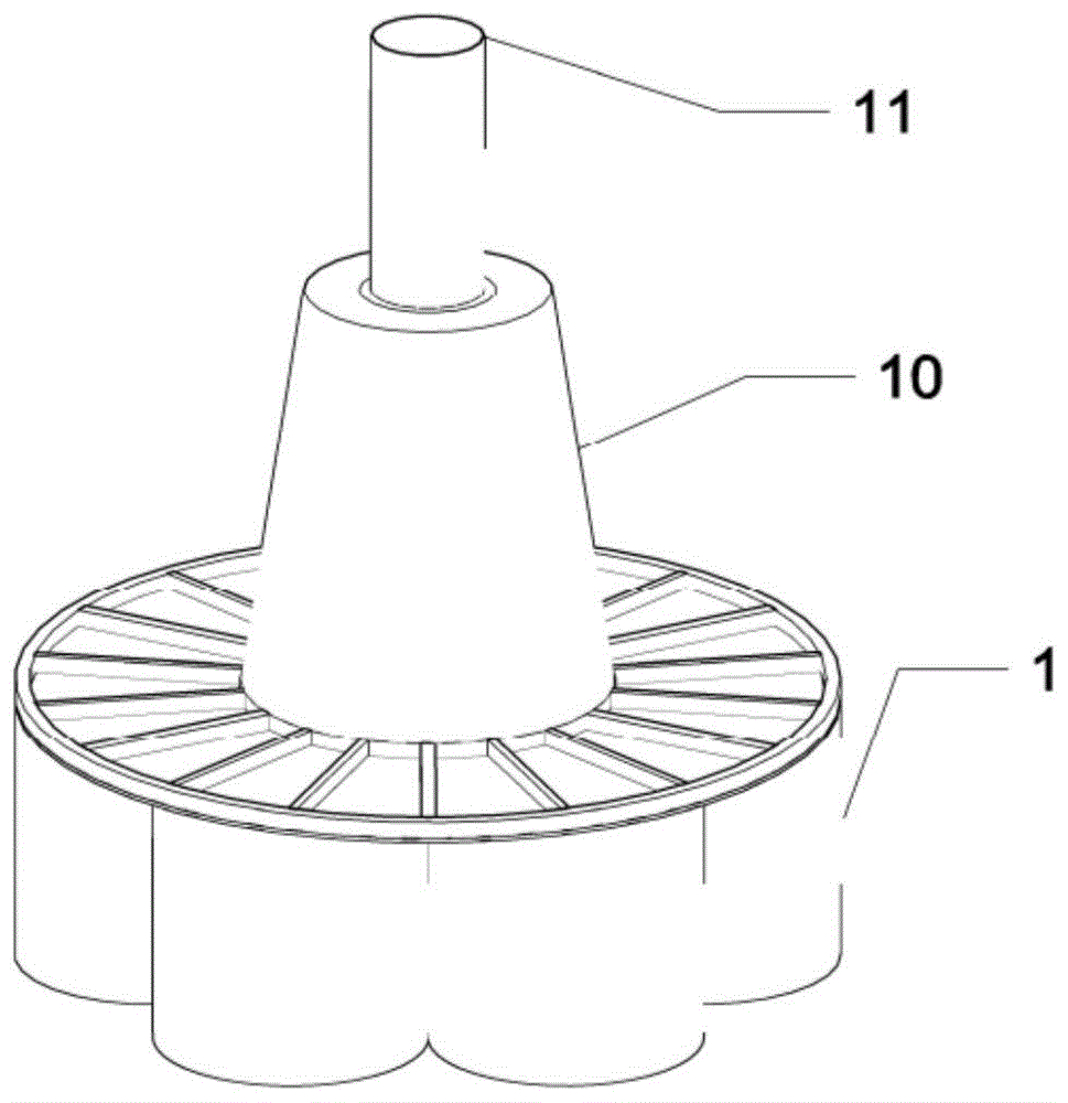
FIG. 1 is a schematic perspective view of a resilient transition section multi-tube base structure provided by the present invention;
FIG. 2 is a top view of a resilient transition section multi-tube base structure provided by the present invention;
FIG. 3 is a cross-sectional view of a resilient transition section multi-barrel base structure provided by the present invention;
FIG. 4 is a schematic structural view of the interconnection of the steel cylinder bases in the resilient transition section multi-cylinder base structure provided by the present invention;
FIG. 5 is a schematic structural view of a resilient transition piece multi-tube base structure provided by the present invention with the transition piece removed;
FIG. 6 is a cross-sectional view of an elastomeric cushioning structure in an elastomeric transition section multi-tube base structure provided by the present invention.
In the figure: 1. a steel cylinder foundation; 2. a steel top plate; 3. a concrete slab; 4. an outer ring beam; 5. a middle ring beam; 6. a first inner ring beam; 7. a second inner ring beam; 8. a concrete main beam; 9. a concrete secondary beam; 10. a concrete transition section; 11. a steel tower drum; 12. an elastic buffer device.
Detailed Description
In order to further understand the contents, features and effects of the present invention, the following embodiments are illustrated and described in detail with reference to the accompanying drawings:
as shown in fig. 1 to 3, the present embodiment discloses an elastic transition section multi-cylinder foundation structure, which includes a plurality of identical steel cylinder foundations 1, steel roof slabs 2, concrete slabs 3, outer ring beams 4, middle ring beams 5, first inner ring beams 6, second inner ring beams 7, main concrete beams 8, secondary concrete beams 9, concrete transition sections 10, and steel towers 11.
As shown in fig. 4, a plurality of identical steel cylinder foundations 1 can form a circle on a horizontal plane according to a central point connecting line, and every two adjacent steel cylinder foundations 1 are welded together, so that the overall rigidity of the foundations is increased, and the buckling during the sinking process is reduced. The number of the steel cylinder bases 1 can form a ring, and is generally 5-8. The steel cylinder foundation 1 is of a steel cylindrical structure, the radius is 3-15m, the height is 5-15m, and the thickness of the cylinder wall is 10-50 mm.
The steel top plate 2 is arranged on the tops of the steel cylinder foundations 1 and welded with the top surfaces of the steel cylinder foundations 1. The steel top plate 2 is generally circular in shape, and the circular shape is tangent to the plurality of steel cylinder foundations 1 simultaneously. The thickness of the steel top plate 2 is 0.006-0.01 m. An upward steel rib plate is arranged at the periphery of the steel top plate 2, and the height of the steel rib plate is the same as the total height of the concrete plate 3 and the outer ring beam 4; the steel rib plates are used for being inserted into the concrete plates 3 and the outer ring beams 4, and the concrete structure is integrally and effectively connected with the steel cylinder foundations 1. The center of the steel top plate 2 is provided with a round hole, the radius of the round hole is 0.5-1.0 time of that of the steel cylinder foundation 1, and the round hole is used for reducing the sinking resistance of the steel cylinder foundations 1 in water.
The concrete plate 3 is arranged on the upper portion of the steel top plate 2, the concrete plate 3 is consistent with the outline of the steel top plate 2, and the thickness of the concrete plate is 0.3-1 m. The concrete slab 3 is poured on the upper part of the steel roof slab 2, and the steel rib plate of the steel roof slab 2 extends upwards into the concrete slab 3, so that the concrete slab 3 and the steel roof slab 2 are firmly combined. The center of the concrete slab 3 is provided with a round hole, the radius of the round hole is consistent with the size of the round hole arranged on the steel top plate 2, and the round hole is also used for reducing the sinking resistance of the steel cylinder foundations 1 in water.
As shown in fig. 4, the top surface of the concrete slab 3 is provided with four ring beams, including an outer ring beam 4, a middle ring beam 5, a first inner ring beam 6 and a second inner ring beam 7. The outer ring beam 4 is positioned on the outer side of the top surface of the concrete slab 3, the outer edge of the outer ring beam is flush with the outer edge of the concrete slab 3, and the shape of the outer ring beam is consistent with that of the edge of the concrete slab 3; the width of the outer ring beam 4 is 0.5-1.5m, and the height is 0.8-1.8 m. The middle ring beam 5 is positioned in the middle of the top surface of the concrete slab 3, is in a ring shape, has the width of 0.5-1.5m and the height of 0.8-1.8 m; the radius of the middle ring beam 5 is 1.5 to 2.5 times of that of the steel tower barrel 11. The second inner ring beam 7 is arranged on the outer side of the first inner ring beam 6, the outer diameter of the first inner ring beam 6 is 0.2m-1m smaller than the inner diameter of the steel tower barrel 11, the width is 0.5 m-2.5 m, and the height is 0.8 m-1.8 m. The inner diameter of the second inner ring beam 7 is 0.2m-1m larger than the outer diameter of the steel tower barrel 11, the width is 0.5-2.5m, and the height is 0.8-1.8 m.
The top surface of the concrete slab 3 is connected with a concrete main beam 8 and a concrete secondary beam 9 between the ring beams. The concrete main beams 8 are uniformly arranged on the top surface of the concrete slab 3 in the radial direction and extend from the second inner ring beam 7 to the outer ring beam 4. In one embodiment of the present invention, the concrete girders 8 include 6, and an included angle between adjacent concrete girders 8 is 60 degrees; the width of the concrete girder 8 is 0.5-1.5m, and the height is 0.8-1.8 m. The concrete secondary beams 9 are uniformly arranged between every two adjacent concrete main beams 8 on the top surface of the concrete slab 3 in the radial direction and extend from the middle ring beam 5 to the outer ring beam 4. In one embodiment of the invention, the concrete secondary beams 9 comprise 12-18, 2-3 concrete secondary beams 9 are arranged between every two adjacent concrete main beams 8, and the included angle between the axes of the adjacent concrete secondary beams 9 is 20-30 degrees.
Concrete transition section 10 is provided with on concrete slab 3 upper portion, and concrete transition section 10 is the linear type thin wall structure of ring cross-section, and bottom ring diameter is greater than top ring diameter. The concrete transition section 10 is of an equal-thickness structure, the wall thickness of the concrete transition section is 0.5-1.5m, and prestressed steel strands are distributed in the middle of the concrete transition section. The circular bottom surface of the concrete transition section 10 is located on the middle ring beam 5, and the circular cross section of the bottom surface is consistent with that of the middle ring beam; the height of the concrete transition section 10 is 20-40 m. The concrete transition section 10 of the linear thin-walled structure helps to transfer the upper load to the concrete beam slab system and further disperse the upper load to the plurality of steel cylinder foundations 1. In addition, the concrete transition section 10 increases the dead weight of the entire structure, so that the entire structure can resist a part of horizontal load by using the dead weight.
A section of steel tower barrel 11 is arranged at the upper part of the concrete transition section 10, and the steel tower barrel 11 penetrates through the concrete transition section 10 and is directly contacted with the concrete slab 3. The bottom end of the steel tower 11 is inserted between the second inner ring beam 7 and the first inner ring beam 6.
As shown in fig. 5, an elastic buffer device 12 is disposed between the steel tower 11 and the top of the concrete transition section 10, and elastic buffer devices 12 are disposed between the bottom of the steel tower 11 and the first inner ring beam 6, and between the bottom of the steel tower 11 and the second inner ring beam 7.
As shown in fig. 6, the elastic buffer device 12 is formed by sequentially adhering a waterproof layer a, an oxidation-resistant layer b, an elastic metal coil c, a first rubber layer d, a rubber bump layer e and a second rubber layer f by using colloid, and has a total thickness of 0.2-1m and a height of 0.8-1.8 m.
The construction method of the multi-cylinder combined foundation structure specifically comprises the following steps:
(1) prefabricating a plurality of steel cylinder foundations 1 on land, arranging the plurality of steel cylinder foundations 1 on a horizontal plane according to a central point connecting line to form a circle, welding the steel cylinder foundations 1 and a steel top plate 2 together, and welding the steel cylinder foundations 1 and the steel top plate 2 together;
(2) taking the steel top plate 2 as a bottom surface template of the concrete plate 3, binding steel bars on the steel top plate 2, and carrying out pouring construction on the concrete plate 3, the outer ring beam 4, the middle ring beam 5, the first inner ring beam 6, the second inner ring beam 7, the concrete main beam 8, the concrete secondary beam 9 and the concrete transition section 10 together;
(3) hoisting the integral structure after the pouring construction into water, checking the air tightness, mounting a steel tower drum 11 on the concrete slab 3, mounting elastic buffer devices 12 between the bottom of the steel tower drum 11 and the first inner ring beam 6, between the bottom of the steel tower drum 11 and the second inner ring beam 7, and between the steel tower drum 11 and the top of the concrete transition section 10, mounting a machine head on the steel tower drum 11, and adjusting the draught of a steel drum foundation according to towing requirements;
(4) carrying out floating towing on the multi-cylinder combined foundation structure and the machine head;
(5) after the multi-cylinder combined foundation structure and the machine head are subjected to floating towing to a designated sea area, self-weight sinking is firstly carried out, and then negative pressure sinking is carried out to a designated position;
(6) and after the sinking is finished, reinforcing the soil body in the steel cylinder foundation 1.
Although the preferred embodiments of the present invention have been described above with reference to the accompanying drawings, the present invention is not limited to the above-described embodiments, which are merely illustrative and not restrictive, and those skilled in the art can make various changes and modifications within the spirit and scope of the present invention without departing from the spirit and scope of the appended claims.