CN110447295B - Method and user equipment for performing beam recovery, and method and base station for supporting the same - Google Patents
Method and user equipment for performing beam recovery, and method and base station for supporting the same Download PDFInfo
- Publication number
- CN110447295B CN110447295B CN201880020133.1A CN201880020133A CN110447295B CN 110447295 B CN110447295 B CN 110447295B CN 201880020133 A CN201880020133 A CN 201880020133A CN 110447295 B CN110447295 B CN 110447295B
- Authority
- CN
- China
- Prior art keywords
- random access
- procedure
- gnb
- configuration information
- downlink
- Prior art date
- Legal status (The legal status is an assumption and is not a legal conclusion. Google has not performed a legal analysis and makes no representation as to the accuracy of the status listed.)
- Active
Links
Images


Classifications
-
- H—ELECTRICITY
- H04—ELECTRIC COMMUNICATION TECHNIQUE
- H04W—WIRELESS COMMUNICATION NETWORKS
- H04W48/00—Access restriction; Network selection; Access point selection
- H04W48/16—Discovering, processing access restriction or access information
-
- H—ELECTRICITY
- H04—ELECTRIC COMMUNICATION TECHNIQUE
- H04W—WIRELESS COMMUNICATION NETWORKS
- H04W72/00—Local resource management
- H04W72/20—Control channels or signalling for resource management
- H04W72/23—Control channels or signalling for resource management in the downlink direction of a wireless link, i.e. towards a terminal
-
- H—ELECTRICITY
- H04—ELECTRIC COMMUNICATION TECHNIQUE
- H04B—TRANSMISSION
- H04B7/00—Radio transmission systems, i.e. using radiation field
- H04B7/02—Diversity systems; Multi-antenna system, i.e. transmission or reception using multiple antennas
- H04B7/04—Diversity systems; Multi-antenna system, i.e. transmission or reception using multiple antennas using two or more spaced independent antennas
- H04B7/06—Diversity systems; Multi-antenna system, i.e. transmission or reception using multiple antennas using two or more spaced independent antennas at the transmitting station
- H04B7/0613—Diversity systems; Multi-antenna system, i.e. transmission or reception using multiple antennas using two or more spaced independent antennas at the transmitting station using simultaneous transmission
- H04B7/0615—Diversity systems; Multi-antenna system, i.e. transmission or reception using multiple antennas using two or more spaced independent antennas at the transmitting station using simultaneous transmission of weighted versions of same signal
- H04B7/0619—Diversity systems; Multi-antenna system, i.e. transmission or reception using multiple antennas using two or more spaced independent antennas at the transmitting station using simultaneous transmission of weighted versions of same signal using feedback from receiving side
- H04B7/0621—Feedback content
- H04B7/0632—Channel quality parameters, e.g. channel quality indicator [CQI]
-
- H—ELECTRICITY
- H04—ELECTRIC COMMUNICATION TECHNIQUE
- H04B—TRANSMISSION
- H04B7/00—Radio transmission systems, i.e. using radiation field
- H04B7/02—Diversity systems; Multi-antenna system, i.e. transmission or reception using multiple antennas
- H04B7/04—Diversity systems; Multi-antenna system, i.e. transmission or reception using multiple antennas using two or more spaced independent antennas
- H04B7/06—Diversity systems; Multi-antenna system, i.e. transmission or reception using multiple antennas using two or more spaced independent antennas at the transmitting station
- H04B7/0686—Hybrid systems, i.e. switching and simultaneous transmission
- H04B7/0695—Hybrid systems, i.e. switching and simultaneous transmission using beam selection
-
- H—ELECTRICITY
- H04—ELECTRIC COMMUNICATION TECHNIQUE
- H04B—TRANSMISSION
- H04B7/00—Radio transmission systems, i.e. using radiation field
- H04B7/02—Diversity systems; Multi-antenna system, i.e. transmission or reception using multiple antennas
- H04B7/04—Diversity systems; Multi-antenna system, i.e. transmission or reception using multiple antennas using two or more spaced independent antennas
- H04B7/08—Diversity systems; Multi-antenna system, i.e. transmission or reception using multiple antennas using two or more spaced independent antennas at the receiving station
- H04B7/0868—Hybrid systems, i.e. switching and combining
- H04B7/088—Hybrid systems, i.e. switching and combining using beam selection
-
- H—ELECTRICITY
- H04—ELECTRIC COMMUNICATION TECHNIQUE
- H04L—TRANSMISSION OF DIGITAL INFORMATION, e.g. TELEGRAPHIC COMMUNICATION
- H04L25/00—Baseband systems
- H04L25/02—Details ; arrangements for supplying electrical power along data transmission lines
- H04L25/0202—Channel estimation
- H04L25/0204—Channel estimation of multiple channels
-
- H—ELECTRICITY
- H04—ELECTRIC COMMUNICATION TECHNIQUE
- H04W—WIRELESS COMMUNICATION NETWORKS
- H04W24/00—Supervisory, monitoring or testing arrangements
- H04W24/04—Arrangements for maintaining operational condition
-
- H—ELECTRICITY
- H04—ELECTRIC COMMUNICATION TECHNIQUE
- H04W—WIRELESS COMMUNICATION NETWORKS
- H04W24/00—Supervisory, monitoring or testing arrangements
- H04W24/10—Scheduling measurement reports ; Arrangements for measurement reports
-
- H—ELECTRICITY
- H04—ELECTRIC COMMUNICATION TECHNIQUE
- H04W—WIRELESS COMMUNICATION NETWORKS
- H04W56/00—Synchronisation arrangements
- H04W56/0005—Synchronisation arrangements synchronizing of arrival of multiple uplinks
-
- H—ELECTRICITY
- H04—ELECTRIC COMMUNICATION TECHNIQUE
- H04W—WIRELESS COMMUNICATION NETWORKS
- H04W72/00—Local resource management
- H04W72/04—Wireless resource allocation
- H04W72/044—Wireless resource allocation based on the type of the allocated resource
- H04W72/046—Wireless resource allocation based on the type of the allocated resource the resource being in the space domain, e.g. beams
-
- H—ELECTRICITY
- H04—ELECTRIC COMMUNICATION TECHNIQUE
- H04W—WIRELESS COMMUNICATION NETWORKS
- H04W72/00—Local resource management
- H04W72/20—Control channels or signalling for resource management
- H04W72/21—Control channels or signalling for resource management in the uplink direction of a wireless link, i.e. towards the network
-
- H—ELECTRICITY
- H04—ELECTRIC COMMUNICATION TECHNIQUE
- H04W—WIRELESS COMMUNICATION NETWORKS
- H04W74/00—Wireless channel access, e.g. scheduled or random access
- H04W74/08—Non-scheduled or contention based access, e.g. random access, ALOHA, CSMA [Carrier Sense Multiple Access]
- H04W74/0833—Non-scheduled or contention based access, e.g. random access, ALOHA, CSMA [Carrier Sense Multiple Access] using a random access procedure
-
- H—ELECTRICITY
- H04—ELECTRIC COMMUNICATION TECHNIQUE
- H04W—WIRELESS COMMUNICATION NETWORKS
- H04W76/00—Connection management
- H04W76/10—Connection setup
- H04W76/19—Connection re-establishment
-
- H—ELECTRICITY
- H04—ELECTRIC COMMUNICATION TECHNIQUE
- H04W—WIRELESS COMMUNICATION NETWORKS
- H04W76/00—Connection management
- H04W76/20—Manipulation of established connections
- H04W76/28—Discontinuous transmission [DTX]; Discontinuous reception [DRX]
-
- H—ELECTRICITY
- H04—ELECTRIC COMMUNICATION TECHNIQUE
- H04W—WIRELESS COMMUNICATION NETWORKS
- H04W56/00—Synchronisation arrangements
- H04W56/001—Synchronization between nodes
- H04W56/0015—Synchronization between nodes one node acting as a reference for the others
-
- H—ELECTRICITY
- H04—ELECTRIC COMMUNICATION TECHNIQUE
- H04W—WIRELESS COMMUNICATION NETWORKS
- H04W76/00—Connection management
- H04W76/20—Manipulation of established connections
- H04W76/27—Transitions between radio resource control [RRC] states
Abstract
When uplink data is generated in a user equipment or when paging data for the same is received from a base station while the user equipment is in a Discontinuous Reception (DRX) mode, the user equipment transmits a scheduling request for beam recovery through a scheduling request channel resource configured in the user equipment. The user equipment receives an uplink grant in response to the scheduling request.
Description
Technical Field
The present invention relates to wireless communication systems. More particularly, the present invention relates to a method and apparatus for performing/supporting a beam recovery procedure.
Background
With the advent and popularity of machine-to-machine (M2M) communications and various devices such as smart phones and tablets, as well as technologies requiring mass data transfer, the data throughput required in cellular networks has increased rapidly. To meet such rapidly increasing data throughput, carrier aggregation techniques, cognitive radio techniques, etc., for effectively adopting more frequency bands, and multiple-input multiple-output (MIMO) techniques, multiple Base Station (BS) cooperation techniques, etc., for increasing data capacity transmitted over limited frequency resources have been developed.
A general wireless communication system performs data transmission/reception through one Downlink (DL) frequency band and one Uplink (UL) frequency band corresponding to the DL frequency band (in the case of Frequency Division Duplex (FDD) mode), or divides a prescribed radio frame into UL time units and DL time units in the time domain and then performs data transmission/reception through the UL/DL time units (in the case of Time Division Duplex (TDD) mode). A Base Station (BS) and a User Equipment (UE) transmit and receive data and/or control information scheduled on a prescribed time unit basis, e.g., on a subframe basis. Data is transmitted and received through a data region configured in the UL/DL subframe, and control information is transmitted and received through a control region configured in the UL/DL subframe. To this end, various physical channels carrying radio signals are formed in the UL/DL subframe. In contrast, the carrier aggregation technique uses a wider UL/DL bandwidth by aggregating a plurality of UL/DL frequency blocks so as to use a wider frequency band, so that more signals can be simultaneously processed relative to a signal when a single carrier is used.
Furthermore, communication environments have evolved to increase the density of nodes accessible to users at the periphery of the nodes. A node refers to a fixed point capable of transmitting/receiving radio signals to/from a UE through one or more antennas. A communication system including high-density nodes may provide a better communication service to UEs through cooperation between the nodes.
As more and more communication devices require higher communication capacity, there has been a need to enhance mobile broadband (eMBB) communication relative to traditional Radio Access Technologies (RATs). In addition, large-scale machine type communication (mtc) that provides various services at any time and at any place by connecting a plurality of devices and objects to each other is one of the main problems to be considered in next-generation communication.
Further, communication systems designed in consideration of reliability and delay sensitive services/UEs are being discussed. Introduction of next generation RATs has been discussed by considering eMBB communication, mtc, ultra-reliable and low latency communication (URLLC), and the like.
Disclosure of Invention
Technical problem
As new radio communication technologies are introduced, the number of User Equipments (UEs) to which a BS should provide service increases in a prescribed resource area, and the amount of data and control information that the BS should transmit to the UEs increases. Since the amount of resources available for the BS to communicate with the UE is limited, a new method in which the BS efficiently receives/transmits uplink/downlink data and/or uplink/downlink control information using limited radio resources is required.
As technology has evolved, overcoming latency or delay has become a significant challenge. Applications whose performance is heavily dependent on delay/latency are increasing. Therefore, a method of reducing latency/delay compared to conventional systems is needed.
Also, with the development of smart devices, a new scheme for efficiently transmitting/receiving a small amount of data or efficiently transmitting/receiving data occurring at a low frequency is required.
In addition, there is a need for a signal transmission/reception method in a system supporting a new radio access technology (NR) using a high frequency band.
Technical objects that can be achieved by the present invention are not limited to what has been particularly described above, and other technical objects that are not described herein will be more clearly understood by those skilled in the art from the following detailed description.
Technical scheme
According to an aspect of the present invention, there is provided a method of performing a beam recovery procedure by a User Equipment (UE) in a wireless communication system. The method comprises the following steps: generating uplink data at the UE or receiving paging information of the UE from a Base Station (BS) when the UE is in a Discontinuous Reception (DRX) mode; transmitting a scheduling request channel through a scheduling request channel resource corresponding to one of the downlink beams; and receiving an uplink grant in response to the scheduling request channel.
In another aspect of the present invention, there is provided a method of supporting a beam recovery procedure by a Base Station (BS) in a wireless communication system. The method comprises the following steps: receiving a scheduling request channel from a User Equipment (UE) through a scheduling request channel resource corresponding to one of downlink beams when the UE is in a Discontinuous Reception (DRX) mode; and sending an uplink grant in response to the scheduling request channel.
In another aspect of the present invention, provided herein is a User Equipment (UE) for performing a beam recovery procedure in a wireless communication system. The UE comprises: a Radio Frequency (RF) unit; and a processor configured to control the RF unit. The processor is configured to: generating uplink data at the UE when the UE is in a Discontinuous Reception (DRX) mode, or controlling an RF unit to receive paging information of the UE from a Base Station (BS); controlling the RF unit to transmit a scheduling request channel through a scheduling request channel resource corresponding to one of the downlink beams; and controls the RF unit to receive the uplink grant in response to the scheduling request channel.
In another aspect of the present invention, there is provided a Base Station (BS) for supporting a beam recovery procedure in a wireless communication system. The BS includes: a Radio Frequency (RF) unit; and a processor configured to control the RF unit. The processor is configured to: controlling the RF unit to receive a scheduling request channel from a User Equipment (UE) through a scheduling request channel resource corresponding to one of downlink beams when the UE is in a Discontinuous Reception (DRX) mode; and controls the RF unit to transmit the uplink grant in response to the scheduling request channel.
In each aspect of the present invention, the scheduling request channel resource may correspond to a best downlink beam measured by the UE among the downlink beams.
In each aspect of the present invention, information indicating respective scheduling request channel resources for a plurality of synchronization signal blocks may be provided to a UE by a BS.
In each aspect of the present invention, the UE may perform measurements on multiple synchronization signal blocks. The scheduling request channel resource may correspond to a synchronization signal block having the highest received power among the plurality of synchronization signal blocks.
In each aspect of the present invention, the UE may perform beam measurement to measure a sounding reference signal of each beam.
In each aspect of the present invention, a beam measurement report for reporting the result of beam measurement through an uplink grant may be transmitted by the UE to the BS.
In each aspect of the present invention, the per-beam measurement reference signal may be a per-beam synchronization signal or a per-beam channel state measurement reference signal.
The above-described embodiments are only some of the embodiments of the present invention, and those skilled in the art can derive and understand various embodiments including technical features of the present invention from the following detailed description of the present invention.
Advantageous effects
According to the present invention, uplink/downlink signals can be efficiently transmitted/received. Thus, the overall throughput of the radio communication system can be improved.
According to the embodiments of the present invention, delay/delay occurring during communication between the user equipment and the base station can be reduced.
Further, due to the development of smart devices, not only a small amount of data but also data that does not occur frequently can be efficiently transmitted/received.
In addition, it is possible to transmit/receive signals in a system supporting a new radio access technology.
It will be appreciated by persons skilled in the art that the effects that can be achieved by the present invention are not limited to what has been particularly described hereinabove and other advantages of the present invention will be more clearly understood from the following detailed description.
Drawings
The accompanying drawings, which are included to provide a further understanding of the invention, illustrate embodiments of the invention and together with the description serve to explain the principle of the invention.
Fig. 1 illustrates a random access procedure in an LTE/LTE-a system.
Fig. 2 illustrates a random access preamble format in a conventional LTE/LTE-a system.
Fig. 3 is a diagram illustrating a concept of Discontinuous Reception (DRX).
Fig. 4 illustrates a slot structure available in a new radio access technology (NR).
Fig. 5 abstractly illustrates a transceiver unit (TXRU) and a hybrid beamforming structure in terms of physical antennas.
Fig. 6 illustrates a cell of a new radio access technology (NR) system.
Fig. 7 illustrates transmission of a Synchronization Signal (SS) block and a RACH resource linked to the SS block.
Fig. 8 illustrates UE state transition. The UE has only one RRC state at a time.
Fig. 9 schematically illustrates a beam recovery procedure according to the present invention.
Fig. 10 is a block diagram illustrating elements of a transmitting apparatus 10 and a receiving apparatus 20 for implementing the present invention.
Detailed Description
Reference will now be made in detail to exemplary embodiments of the invention, examples of which are illustrated in the accompanying drawings. The detailed description set forth below in connection with the appended drawings is intended as an explanation of exemplary embodiments of the present invention and is not intended to represent the only embodiments in which the present invention may be practiced. The following detailed description includes specific details in order to provide a thorough understanding of the invention. It will be apparent, however, to one skilled in the art that the present invention may be practiced without these specific details.
In some instances, well-known structures and devices are omitted or shown in block diagram form, focusing on important features of the structures and devices so as not to obscure the concept of the present invention. The same reference numbers will be used throughout the specification to refer to the same or like parts.
The following techniques, apparatus, and systems may be applied to various wireless multiple access systems. Examples of multiple-access systems include Code Division Multiple Access (CDMA) systems, frequency Division Multiple Access (FDMA) systems, time Division Multiple Access (TDMA) systems, orthogonal Frequency Division Multiple Access (OFDMA) systems, single carrier frequency division multiple access (SC-FDMA) systems, and multi-carrier frequency division multiple access (MC-FDMA) systems. CDMA may be implemented by a radio technology such as Universal Terrestrial Radio Access (UTRA) or CDMA 2000. TDMA may be implemented by radio technologies such as global system for mobile communications (GSM), general Packet Radio Service (GPRS), or enhanced data rates for data (EDGE) GSM evolution. OFDMA may be implemented by a radio technology such as Institute of Electrical and Electronics Engineers (IEEE) 802.11 (Wi-Fi), IEEE 802.16 (WiMAX), IEEE 802.20, or evolved UTRA (E-UTRA). UTRA is part of the Universal Mobile Telecommunications System (UMTS). Third generation partnership project (3 GPP) Long Term Evolution (LTE) is part of evolved UMTS (E-UMTS) using E-UTRA. The 3GPP LTE uses OFDMA in DL and SC-FDMA in UL. LTE-advanced (LTE-a) is an evolved version of 3GPP LTE. For ease of description, it is assumed that the present invention is applied to a 3GPP based communication system, such as LTE/LTE-A, NR. However, the technical features of the present invention are not limited thereto. For example, although the following detailed description is given based on a mobile communication system corresponding to a 3GPP LTE/LTE-a/NR system, aspects of the present invention that are not specific to the 3GPP LTE/LTE-a/NR system may be applied to other mobile communication systems.
For example, the present invention is applicable to contention-based communication such as Wi-Fi and non-contention-based communication as in a 3GPP LTE/LTE-a system in which an eNB allocates DL/UL time/frequency resources to a UE and the UE receives a DL signal and transmits a UL signal according to the resource allocation of the eNB. In the non-contention based communication scheme, an Access Point (AP) or a control node for controlling the AP allocates resources for communication between a UE and the AP, whereas in the contention based communication scheme, resources are occupied by contention communication between UEs desiring to access the AP. A contention-based communication scheme will now be briefly described. One contention-based communication scheme is Carrier Sense Multiple Access (CSMA). CSMA refers to a probabilistic Medium Access Control (MAC) protocol for confirming that there is no other traffic on a shared transmission medium, such as a frequency band (also referred to as a shared channel), before a node or communication device transmits the traffic on the same shared transmission medium. In CSMA, a transmitting device determines whether another transmission is being performed before attempting to send traffic to a receiving device. In other words, the transmitting device attempts to detect the presence of a carrier from another transmitting device before attempting to perform a transmission. Once listening to the carrier, the sending device waits for another transmitting device that is transmitting to complete the transmission before performing its transmission. Thus, CSMA can be used as a communication scheme based on the "sense-before-send" or "listen-before-talk" principle. Schemes for avoiding collisions between transmitting devices in contention-based communication systems using CSMA include carrier sense multiple access with collision detection (CSMA/CD) and/or carrier sense multiple access with collision avoidance (CSMA/CA). CSMA/CD is a collision detection scheme in a wired Local Area Network (LAN) environment. In CSMA/CD, a Personal Computer (PC) or server wishing to communicate in an ethernet environment first confirms whether communication is occurring on the network, and if another device is carrying data on the network, the PC or server waits and then transmits the data. That is, when two or more users (e.g., PCs, UEs, etc.) simultaneously transmit data, collision occurs between simultaneous transmissions, and CSMA/CD is a scheme for flexibly transmitting data by monitoring collision. A transmitting device using CSMA/CD adjusts its data transmission by listening to data transmissions performed by another device using certain rules. CSMA/CA is a MAC protocol specified in the IEEE 802.11 standard. A Wireless LAN (WLAN) system conforming to the IEEE 802.11 standard uses CA, i.e., a collision avoidance scheme, without using CSMA/CD already used in the IEEE 802.3 standard. The transmitting device always listens to the carrier of the network and if the network is empty, the transmitting device waits for a determined time according to its position registered in the list and then transmits the data. Various methods are used to determine the priorities of the transmitting devices in the list and to reconfigure the priorities. In systems according to some versions of the IEEE 802.11 standard, collisions may occur, and in this case, a collision listening procedure is performed. A transmitting device using CSMA/CA uses a certain rule to avoid collision between its data transmission and that of another transmitting device.
In the embodiments of the present invention described below, the term "assumption (assumption)" may mean that a subject (subject) of a transmission channel transmits the channel according to the corresponding "assumption (assumption)". This may also mean that, assuming that a channel has been transmitted according to the "assumption (assumption)", the body of the reception channel receives or decodes the channel in a form conforming to the "assumption (assumption)".
In the present invention, puncturing a physical channel on a specific resource means that a signal of the physical channel is mapped to the specific resource in a resource mapping procedure of the physical channel, but a part of the signal mapped to the punctured resource is excluded in transmitting the physical channel. In other words, the specific resources punctured in the resource mapping process of the physical channel are counted as resources for the physical channel, and the signal mapped to the specific resources among the signals of the physical channel is not actually transmitted. Assuming that a signal mapped to a specific resource is not transmitted, a receiver of the physical channel receives, demodulates, or decodes the physical channel. On the other hand, rate matching of a physical channel on a specific resource means that the physical channel is never mapped to the specific resource in the course of resource mapping of the physical channel, and thus the specific resource is not used for transmission of the physical channel. In other words, the rate-matched resources are not counted as resources for the physical channel in the resource mapping process of the physical channel. A receiver of a physical channel receives, demodulates or decodes the physical channel assuming that a specific rate matching resource is not used for mapping and transmission of the physical channel.
In the present invention, a User Equipment (UE) may be a fixed or mobile device. Examples of the UE include various devices that transmit and receive user data and/or various control information to and from a Base Station (BS). A UE may be referred to as a Terminal Equipment (TE), a Mobile Station (MS), a Mobile Terminal (MT), a User Terminal (UT), a Subscriber Station (SS), a wireless device, a Personal Digital Assistant (PDA), a wireless modem, a handheld device, etc. In addition, in the present invention, a BS generally refers to a fixed station that performs communication with a UE and/or another BS, and exchanges various data and control information with the UE and the other BS. The BS may be referred to as an Advanced Base Station (ABS), a Node B (NB), an evolved node B (eNB), a Base Transceiver System (BTS), an Access Point (AP), a Processing Server (PS), and the like. Specifically, the BS of UTRAN is called node-B, the BS of E-UTRAN is called eNB, and the BS of the new radio access technology network is called gNB. In describing the present invention, the BS will be referred to as a gNB.
In the present invention, a node refers to a fixed point capable of transmitting/receiving a radio signal through communication with a UE. Regardless of its terminology, various types of gnbs may be used as nodes. For example, a BS, node B (NB), enodeb (eNB), pico cell eNB (PeNB), home eNB (HeNB), gNB, relay, repeater, etc. may be a node. In addition, the node may not be a gNB. For example, a node may be a Radio Remote Head (RRH) or a Radio Remote Unit (RRU). The RRH or RRU typically has a lower power level than the power level of the gNB. Since an RRH or an RRU (hereinafter referred to as RRH/RRU) is generally connected to the gNB through a dedicated line such as an optical cable, cooperative communication between the RRH/RRU and the gNB can be smoothly performed as compared with cooperative communication between the gnbs connected through a radio line. At least one antenna is mounted per node. An antenna may mean a physical antenna or mean an antenna port or a virtual antenna.
In the present invention, a cell refers to a prescribed geographical area to which one or more nodes provide communication services. Therefore, in the present invention, communicating with a specific cell may mean communicating with a gNB or a node providing a communication service to the specific cell. In addition, the DL/UL signal of a specific cell means a DL/UL signal from/to a gNB or node providing a communication service to the specific cell. A node providing the UL/DL communication service to the UE is particularly referred to as a serving node, and a cell providing the UL/DL communication service through the serving node is particularly referred to as a serving cell. Further, the channel state/quality of a particular cell is the channel state/quality of a channel or communication link formed between the gNB or node providing communication service to the particular cell and the UE. In a 3 GPP-based communication system, a UE may measure a DL channel state received from a specific node using CRS transmitted on cell-specific reference signal (CRS) resources and/or channel state information reference signal (CSI-RS) resources allocated to the specific node through an antenna port of the specific node.
Meanwhile, the 3 GPP-based communication system uses the concept of a cell in order to manage radio resources and the cell associated with the radio resources is distinguished from cells of a geographical area.
A "cell" of a geographical area may be understood as a coverage area in which a node may provide a service using a carrier, and a "cell" of radio resources is associated with a Bandwidth (BW) which is a frequency range configured by the carrier. Since the DL coverage, which is the range in which a node can transmit a valid signal, and the UL coverage, which is the range in which a node can receive a valid signal from a UE, depend on the carrier carrying the signal, the coverage of the node may be associated with the coverage of the "cell" of the radio resource used by the node. Thus, the term "cell" may sometimes be used to indicate a service coverage of a node, other times may indicate radio resources, or at other times may indicate a range in which a signal using radio resources may arrive with significant strength.
Meanwhile, the 3GPP communication standard uses the concept of a cell to manage radio resources. The "cell" associated with a radio resource is defined by a combination of downlink resources and uplink resources, i.e., a combination of DL CC and UL CC. The cell may be configured by only downlink resources, or may be configured by downlink resources and uplink resources. If carrier aggregation is supported, linkage between carrier frequencies of downlink resources (or DL CCs) and carrier frequencies of uplink resources (or UL CCs) may be indicated through system information. For example, the combination of DL resources and UL resources may be indicated by linkage of system information block type 2 (SIB 2). The carrier frequency means a center frequency of each cell or CC. A cell operating on a primary frequency may be referred to as a primary cell (Pcell) or PCC, and a cell operating on a secondary frequency (or SCC) may be referred to as a secondary cell (Scell) or SCC. A carrier corresponding to a Pcell on the downlink will be referred to as a downlink primary CC (DL PCC), and a carrier corresponding to a Pcell on the uplink will be referred to as an uplink primary CC (UL PCC). Scell means a cell that can be configured and used to provide additional radio resources after completion of Radio Resource Control (RRC) connection establishment. The Scell may form a serving cell set for the UE together with the Pcell according to the UE's capabilities. A carrier corresponding to Scell on the downlink will be referred to as a downlink secondary CC (DL SCC), and a carrier corresponding to Scell on the uplink will be referred to as an uplink secondary CC (UL SCC). Although the UE is in the RRC-CONNECTED state, if the UE is not configured with carrier aggregation or does not support carrier aggregation, there is only a single serving cell configured by the Pcell.
The 3 GPP-based communication standard defines DL physical channels corresponding to resource elements carrying information derived from higher layers and DL physical signals corresponding to resource elements used by the physical layer but not carrying information derived from higher layers. For example, a Physical Downlink Shared Channel (PDSCH), a Physical Broadcast Channel (PBCH), a Physical Multicast Channel (PMCH), a Physical Control Format Indicator Channel (PCFICH), a Physical Downlink Control Channel (PDCCH), and a physical hybrid ARQ indicator channel (PHICH) are defined as DL physical channels, and a reference signal and a synchronization signal are defined as DL physical signals. Reference Signals (RSs), also known as pilots, refer to special waveforms of predefined signals known to both the BS and the UE. For example, a cell-specific RS (CRS), a UE-specific RS (UE-RS), a Positioning RS (PRS), and a channel state information RS (CSI-RS) may be defined as DL RSs. Meanwhile, the 3GPP LTE/LTE-a standard defines UL physical channels corresponding to resource elements carrying information derived from a higher layer and UL physical signals corresponding to resource elements used by the physical layer but not carrying information derived from a higher layer. For example, a Physical Uplink Shared Channel (PUSCH), a Physical Uplink Control Channel (PUCCH), and a Physical Random Access Channel (PRACH) are defined as UL physical channels, and a demodulation reference signal (DM RS) for UL control/data signals and a Sounding Reference Signal (SRS) for UL channel measurement are defined as UL physical signals.
In the present invention, a Physical Downlink Control Channel (PDCCH), a Physical Control Format Indicator Channel (PCFICH), a physical hybrid automatic repeat request indicator channel (PHICH), and a Physical Downlink Shared Channel (PDSCH) refer to a time-frequency resource or Resource Element (RE) set carrying Downlink Control Information (DCI), a time-frequency resource or RE set carrying Control Format Indicator (CFI), a time-frequency resource or RE set carrying downlink Acknowledgement (ACK)/Negative ACK (NACK), and a time-frequency resource or RE set carrying downlink data, respectively. In addition, the Physical Uplink Control Channel (PUCCH), the Physical Uplink Shared Channel (PUSCH), and the Physical Random Access Channel (PRACH) refer to a time-frequency resource or RE set carrying Uplink Control Information (UCI), a time-frequency resource or RE set carrying uplink data, and a time-frequency resource or RE set carrying a random access signal, respectively. In the present invention, in particular, the time-frequency resources or REs assigned or belonging to PDCCH/PCFICH/PHICH/PDSCH/PUCCH/PUSCH/PRACH are referred to as PDCCH/PCFICH/PHICH/PDSCH/PUCCH/PUSCH/PRACH REs or PDCCH/PCFICH/PHICH/PDSCH/PUCCH/PUSCH/PRACH time-frequency resources, respectively. Therefore, in the present invention, PUCCH/PUSCH/PRACH transmission of a UE is conceptually the same as UCI/uplink data/random access signal transmission on PUSCH/PUCCH/PRACH, respectively. In addition, PDCCH/PCFICH/PHICH/PDSCH transmission of gNB is conceptually the same as downlink data/DCI transmission on PDCCH/PCFICH/PHICH/PDSCH, respectively.
Hereinafter, the OFDM symbols/subcarriers/REs to which or for which CRS/DMRS/CSI-RS/SRS/UE-RS/TRS is assigned or configured will be referred to as CRS/DMRS/CSI-RS/SRS/UE-RS/TRS symbols/carriers/subcarriers/REs. For example, an OFDM symbol to which or to which a Tracking RS (TRS) is assigned or configured is referred to as a TRS symbol, a subcarrier to which or to which a TRS is assigned or configured is referred to as a TRS subcarrier, and an RE to which or to which a TRS is assigned or configured is referred to as a TRS RE. In addition, a subframe configured for TRS transmission is referred to as a TRS subframe. Also, a subframe in which a broadcast signal is transmitted is referred to as a broadcast subframe or a PBCH subframe, and a subframe in which a synchronization signal (e.g., PSS and/or SSS) is transmitted is referred to as a synchronization signal subframe or a PSS/SSS subframe. The OFDM symbols/subcarriers/REs to which or for which PSS/SSS is assigned or configured are referred to as PSS/SSS symbols/subcarriers/REs, respectively.
In the present invention, a CRS port, a UE-RS port, a CSI-RS port, and a TRS port refer to an antenna port configured to transmit a CRS, an antenna port configured to transmit a UE-RS, an antenna port configured to transmit a CSI-RS, and an antenna port configured to transmit a TRS, respectively. Antenna ports configured to transmit CRS may be distinguished from each other by locations of REs occupied by CRS according to CRS ports, antenna ports configured to transmit UE-RS may be distinguished from each other by locations of REs occupied by UE-RS according to UE-RS ports, and antenna ports configured to transmit CSI-RS may be distinguished from each other by locations of REs occupied by CSI-RS according to CSI-RS ports. Thus, the term CRS/UE-RS/CSI-RS/TRS port may also be used to indicate the pattern of REs occupied by CRS/UE-RS/CSI-RS/TRS in a predetermined resource region.
For terms and techniques not described in detail in the present invention, reference may be made to 3GPP LTE/LTE-a standard documents, such as, for example, 3GPP TS 36.211, 3GPP TS 36.212, 3GPP TS36.213, 3GPP TS 36.321, and 3GPP TS 36.331, and 3GPP NR standard documents, such as, for example, 3GPP TS 38.211, 3GPP TS 38.212, 3GPP 38.213, 3GPP 38.214, 3GPP 38.215, 3GPP TS 38.321, and 3GPP TS 36.331.
The operations first performed by the UE to receive services associated with a particular system include: acquiring time and frequency synchronization of a corresponding system, receiving basic System Information (SI), and synchronizing uplink timing with an uplink. This procedure will be referred to as an initial access procedure. The initial access procedure generally includes a synchronization procedure and a RACH procedure (i.e., a random access procedure). In an LTE/LTE-A system, when a UE is powered on or desires to access a new cell, the UE performs an initial cell search procedure including acquiring time and frequency synchronization with the cell and detecting a physical layer cell identity N of the cell cell ID . To this end, the UE may receive synchronization signals, e.g., a Primary Synchronization Signal (PSS) and a Secondary Synchronization Signal (SSS), from the eNB, thereby establishing synchronization with the eNB and acquiring information such as a cell Identification (ID). For convenience of description, a synchronization procedure in the LTE/LTE-a system will be briefly described again.
PSS: symbol timing acquisition, frequency synchronization, and cell ID detection within a cell ID group (three hypotheses).
SSS: cell ID group detection (168 groups), 10ms frame boundary detection, CP detection (two types).
PBCH decoding: antenna configuration, 40ms timing detection, system information, system bandwidth, etc.
That is, the UE acquires OFDM symbol timing and subframe timing based on PSS and SSS, and also acquires a cell ID, and acquires important information in a corresponding system by descrambling and decoding PBCH using the cell ID. After completing the synchronization procedure, the UE performs a random access procedure. In other words, after the initial cell search procedure, the UE may perform a random access procedure to complete access to the eNB. To this end, the UE may transmit a preamble through a Physical Random Access Channel (PRACH), and receive a response message to the preamble through a PDCCH and a PDSCH. After performing the above procedure, the UE may perform PDCCH/PDSCH reception and PUSCH/PUCCH transmission as a normal UL/DL transmission procedure. The random access procedure is also referred to as a Random Access Channel (RACH) procedure. The random access procedure is used for various purposes including initial access, adjustment of UL synchronization, resource allocation, and handover.
The random access procedure is classified into a contention-based procedure and a dedicated (i.e., non-contention-based) procedure. A contention-based random access procedure is generally used for initial access, and a dedicated random access procedure is restrictively used for handover. In the contention-based random access procedure, the UE randomly selects a RACH preamble sequence. Therefore, multiple UEs may transmit the same RACH preamble sequence, requiring a contention resolution procedure. On the other hand, in the dedicated random access procedure, the UE uses a RACH preamble sequence uniquely assigned to the corresponding UE. Accordingly, the UE may perform the random access procedure without contending with another UE.
The contention based random access procedure includes the following four steps. Hereinafter, the messages transmitted in steps 1 to 4 may be referred to as 1 to 4 (message 1 to message 4).
-step 1: RACH preamble (via PRACH) (UE to eNB)
-step 2: random Access Response (RAR) (via PDCCH or PDSCH) (eNB to UE)
-a step 3: layer 2/layer 3 messages (via PUSCH) (UE to eNB)
-step 4: contention resolution message (eNB to UE)
The dedicated random access procedure includes the following three steps. Hereinafter, the messages transmitted in steps 0 to 2 may be referred to as messages 0 to 2 (message 0 to message 2). As part of the random access procedure, uplink transmissions corresponding to the RAR may be performed (i.e., step 3). The dedicated random access procedure may be triggered using a PDCCH (hereinafter, PDCCH order) for ordering RACH preamble transmission.
-step 0: RACH preamble allocation by dedicated signaling (eNB to UE)
-step 1: RACH preamble (via PRACH) (UE to eNB)
-step 2: random Access Response (RAR) (via PDCCH or PDSCH) (eNB to UE)
After transmitting the RACH preamble, the UE attempts to receive a Random Access Response (RAR) within a preset time window. Specifically, the UE attempts to detect a PDCCH (hereinafter, RA-RNTI PDCCH) with a random access radio network temporary identifier (RA-RNTI) in a time window (e.g., masking the CRC with the RA-RNTI on the PDCCH). In detecting RA-RNTI PDCCH, the UE checks whether there is a RAR directed to it for the PDSCH corresponding to RA-RNTI PDCCH. The RAR includes Timing Advance (TA) information indicating timing offset information for UL synchronization, UL resource allocation information (UL grant information), and a temporary UE identifier (e.g., temporary cell-RNTI (TC-RNTI)). The UE may perform (e.g., msg 3) UL transmission according to the TA value and resource allocation information in the RAR. HARQ is applied to UL transmissions corresponding to RAR. Accordingly, after transmitting the Msg3, the UE may receive reception response information (e.g., PHICH) corresponding to the Msg 3.
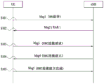
Fig. 1 illustrates a random access procedure in an LTE/LTE-a system. The RRC state changes according to RRC connection. The RRC state means whether or not an entity of the RRC layer of the UE is logically connected with an entity of the RRC layer of the eNB. A state in which an entity of the RRC layer of the UE is connected with an entity of the RRC layer of the eNB means an RRC connected state, and a state in which an entity of the RRC layer of the UE is not connected with an entity of the RRC layer of the eNB means an RRC idle state. The existence of the idle-state UE is recognized in units of a large area, and the UE should transition to a CONNECTED state (RRC _ CONNECTED) to receive a conventional mobile communication service such as voice or data. When a user first turns on power of the UE, the UE is in an idle mode in a corresponding cell after searching for a suitable cell. When an RRC connection is required, the UE in the idle mode establishes an RRC connection with the RRC layer of the eNB through an RRC connection procedure and transitions to an RRC connected state. The RRC connection procedure includes a procedure of transmitting an RRC connection request message from the UE to the eNB, a procedure of transmitting an RRC connection setup message from the eNB to the UE, and a procedure of transmitting an RRC connection setup complete message from the UE to the eNB. Since UL grant is required for transmitting the RRC connection request message, the idle-mode UE should perform a RACH procedure to acquire the UL grant. That is, the UE should transmit an RA preamble (i.e., message 1) (S101) and receive a RAR (i.e., message 2) as a response to the RA preamble (S102). The UE transmits a message 3 including an RRC connection request message to the eNB according to the resource allocation information (i.e., scheduling information) and the timing advance value within the RAR (S103). If an RRC connection request message is received from the UE, the eNB accepts an RRC connection request of the UE if there are sufficient radio resources, and transmits an RRC connection setup message, which is a response message, to the UE (S104). If the UE receives the RRC connection setup message, the UE transmits an RRC connection setup complete message to the eNB (S105). If the UE successfully transmits the RRC connection setup complete message, the UE establishes an RRC connection with the eNB and transitions to an RRC connected mode. That is, if the RACH procedure is completed, the UE becomes in a state of being connected with a corresponding cell.
Fig. 2 illustrates a random access preamble format in a conventional LTE/LTE-a system.
In the conventional LTE/LTE-A system, a random access preamble, i.e., RACH preamble, is included in a physical layer having a length T CP And has a length of T SEQ The sequence portion of (a). Parameter value T CP And T SEQ Listed in the table below and depending on the frame structure and random access configuration. The preamble format is controlled by higher layers. In a 3GPP LTE/LTE-a system, PRACH configuration information is signaled through system information and mobility control information of a cell. PRACH configuration information indicates a root sequence index, a cyclic shift unit N of a Zadoff-Chu (ZC) sequence CS Length of the root sequence and preamble format, which will be used for RACH procedure in the cell. In 3GPP LTE/LTE-a systems, the preamble format and PRACH occasion, which is the time when a RACH preamble can be sent, are indicated by the PRACH configuration index, which is part of the RACH configuration information (see section 5.7 of 3GPP TS 36.211 and "PRACH-Config" of 3GPP TS 36.331). The length of a ZC sequence used for the RACH preamble is determined according to the preamble format.
TABLE 1
| Preamble formats | T CP | T SEQ |
| 0 | 3168·T s | 24576· |
| 1 | 21024·T s | 24576· |
| 2 | 6240· |
2·24576· |
| 3 | 21024· |
2·24576· |
| 4 | 448·T s | 4096·T s |
In LTE/LTE-a systems, the RACH preamble is transmitted in a UL subframe. The transmission of the random access preamble is limited to certain time and frequency resources. These resources are called PRACH resources and are numbered in increasing order of subframe number within a radio frame and PRB in the frequency domainSo that index 0 corresponds to the lowest numbered PRB and subframe within the radio frame. Random access resources are defined according to PRACH configuration index (refer to 3gpp TS 36.211 standard document). The PRACH configuration index is given by higher layer signals (sent by the eNB). In an LTE/LTE-a system, the subcarrier spacing Δ f is 15kHz or 7.5kHz. However, the subcarrier spacing Δ f of the random access preamble RA Is 1.25kHz or 0.75kHz. Fig. 3 is a diagram illustrating a concept of Discontinuous Reception (DRX).
In LTE/LTE-a systems, the UE performs DRX to reduce its power consumption due to continuous monitoring of the PDCCH, where monitoring means attempting to decode each PDCCH in the PDCCH candidate set. Without DRX, the UE must always wake up in order to decode downlink data, since data in the downlink can arrive at any time. This has a serious impact on the power consumption of the UE. The UE may be configured by RRC with a DRX function for controlling PDCCH monitoring activity of the UE with the following identifiers: a cell radio network temporary identifier (C-RNTI), which is a unique identifier used to identify RRC connection and scheduling, a Transmit Power Control (TPC) -PUCCH-RNTI, which is an identifier used for power control of the PUCCH, and a semi-persistent scheduling C-RNTI, which is a unique identifier used for semi-persistent scheduling (if configured). When in RRC _ CONNECTED, if DRX is configured, the UE is allowed to discontinuously monitor the PDCCH using DRX operation; otherwise the UE continuously monitors the PDCCH. Referring to fig. 3, if DRX is configured for a UE in an RRC _ CONNECTED state, the UE attempts to receive a downlink channel PDCCH, i.e., performs PDCCH monitoring only during a predetermined period, and does not perform PDCCH monitoring during the remaining period. The period of time during which the UE should monitor the PDCCH is referred to as the "on duration". Each DRX cycle defines an on duration. That is, the DRX cycle specifies the periodic repetition of the on duration followed by a possible period of inactivity as shown in fig. 3.
The UE always monitors the PDCCH during the on duration in one DRX cycle, and the DRX cycle determines a period in which the on duration is set. The DRX cycle is classified into a long DRX cycle and a short DRX cycle according to a period of the DRX cycle. The long DRX cycle may minimize battery consumption of the UE, whereas the short DRX cycle may minimize data transmission delay.
When the UE receives the PDCCH during the on duration in the DRX cycle, additional transmissions or retransmissions may occur during periods other than the on duration. Therefore, the UE should monitor the PDCCH during a period except for the on-duration. That is, the UE should perform PDCCH monitoring during a period in which the inactivity management timer drx-inactivity timer or the retransmission management timer drx-retransmission timer and the on duration management timer onDurationTimer are running.
The RRC controls DRX operation by configuring the values of timers onDurationTimer, DRX-inactivity timer, DRX-retransmission timer (one per DL HARQ process except for the broadcast process), DRX-ulretransmission timer (one per asynchronous UL HARQ process), longDRX-Cycle, drxStartOffset, and optionally drxShortCycleTimer and shortDRX-Cycle. The eNB provides the UE with DRX configuration information including these parameters through RRC signaling. The UE receives DRX configuration information. A DL HARQ RTT timer per DL HARQ process (except for the broadcast process) and a UL HARQ RTT timer per asynchronous UL HARQ process are also defined. The onDurationTimer specifies the number of consecutive PDCCH subframes at the beginning of the DRX cycle. drx-inactivity timer specifies the number of consecutive PDCCH subframes after the subframe in which the PDCCH indicates initial UL, DL or SL user data transmission for this UE. The drx-retransmission timer specifies the maximum number of consecutive PDCCH subframes until a DL retransmission is received. The drx-ulretransmission timer specifies the maximum number of consecutive PDCCH subframes until a grant of UL retransmission is received. drxStartOffset specifies the subframe where the DRX cycle starts. drxShortCycleTimer specifies the number of consecutive subframes that the UE should follow the short DRX cycle. DL HARQ RTT timer specifies the minimum number of subframes before the UE expects a DL HARQ retransmission. The UL HARQ RTT timer specifies the minimum number of subframes before the UE expects a UL HARQ retransmission grant.
The value of each timer is defined as the number of subframes. The number of subframes is counted until the value of the timer is reached. If the value of the timer is met, the timer expires. The timer runs once started until it is stopped or until it expires; otherwise it is not running. If the timer is not running, it can be started, and if running, it can be restarted. The timer is always started or restarted from its initial value.
In addition, the UE should perform PDCCH monitoring during random access or when the UE transmits a scheduling request and attempts to receive a UL grant.
The period of time during which the UE should perform PDCCH monitoring is referred to as an active time. The active time includes a conduction duration of the periodic monitoring PDCCH and a time interval during which the PDCCH is monitored when the event is generated. When configuring the DRX cycle, the active time includes the following times:
the > onDurationTimer or drx-InactivityTimer or drx-RecransmissionTimer or drx-ULRecransmissionTimer or mac-contentionResolutionTimer is running; or
Transmitting a scheduling request on PUCCH and pending; or
Uplink grants for pending HARQ retransmissions can occur and there is data in the respective HARQ buffer for the synchronous HARQ process; or
After successful reception of a random access response to a preamble not selected by the UE, a PDCCH indicating a new transmission addressed to the C-RNTI of the UE has not been received.
Here, the mac-ContentionResolutionTimer specifies the maximum number of consecutive PDCCH subframes that the UE should monitor after sending Msg 3. When DRX is configured for each subframe, the MAC entity should:
if the HARQ RTT timer expires in this subframe and the data of the corresponding HARQ process is not successfully decoded:
and > > starting drx-retransmission timer for the corresponding HARQ process.
If DRX command MAC control element or long DRX command MAC control element is received:
> > stop the onDurationTimer;
< lambda > stop drx InactivityTimer.
If DRX-inactivity timer expires or a DRX command MAC control element is received in this subframe:
> > stop the onDurationTimer;
< lambda > stop drx InactivityTimer.
If DRX-inactivity timer expires or a DRX command MAC control element is received in this subframe:
> > if the short DRX cycle is configured:
> > start or restart the drxShortCycleTimer;
> > use short DRX cycle.
And > > otherwise:
use long DRX cycle.
If drxShortCycleTimer expires in this subframe:
use long DRX cycle.
If a short DRX Cycle is used and { (SFN x 10) + subframe number } modulo (shortDRX-Cycle) = (drxStartOffset) modulo (shortDRX-Cycle); or
If a long DRX Cycle is used and { (SFN x 10) + subframe number } modulo (longDRX-Cycle) = drxStartOffset:
> > start the onDurationTimer.
During active time, for a PDCCH subframe, if the subframe is not needed for uplink transmission for half-duplex FDD UE operation, and if the subframe is not part of a configured measurement gap;
monitoring a PDCCH;
> > if the PDCCH indicates DL transmission or if DL assignment has been configured for this subframe:
> > starting a HARQ RTT timer for a corresponding HARQ process;
> > stop the drx-retransmission timer for the corresponding HARQ process.
> > if PDCCH indicates a new transmission (DL or UL):
> > start or restart the drx-InactivityTimer.
When not in active time, type 0 triggered SRS is not reported (refer to 3gpp ts36.213 standard document).
If CQI masking is set by the upper layer (e.g., RRC) (CQI-Mask):
> > when the onDurationTimer is not running, CQI/PMI/RI/PTI on PUCCH is not reported.
Else:
> > when in active time, not reporting CQI/PMI/RI/PTI on PUCCH.
Whether or not the UE is monitoring the PDCCH, the UE receives and sends HARQ feedback and sends type 1 triggered SRS (see 3gpp TS36.213 standard documents).
In the above description, a PDCCH subframe refers to a subframe having a PDCCH. For a UE that is not configured with any TDD serving cell, this means any subframe; for a UE configured with at least one TDD serving cell, if the UE is capable of receiving and transmitting simultaneously in an aggregated cell, this means a union over downlink subframes and all serving cells (except the serving cell configured with the schedulingCellId parameter provided by RRC signaling) that include the DwPTS of the TDD UL/DL configuration indicated by the TDD-Config (see 3gpp TS 36.331) parameter provided by RRC signaling; otherwise, this represents a subframe in which the SpCell is configured with a downlink subframe or a subframe including DwPTS of TDD UL/DL configuration indicated by TDD-Config.
Recently, as more and more communication devices have demanded higher communication capacity, mobile broadband has to be enhanced with respect to conventional Radio Access Technologies (RATs). In addition, large-scale machine type communication that provides various services regardless of time and place by connecting a plurality of devices and objects to each other is one of the major problems to be considered in next-generation communication. Further, communication system designs are being discussed in which reliability and delay sensitive services/UEs are considered. Introduction of next generation RATs has been discussed by considering enhanced mobile broadband communication, large-scale MTC, ultra-reliable and low latency communication (URLLC), and the like. In the current 3GPP, research is being conducted on a next-generation mobile communication system following the EPC. In the present invention, for convenience, the corresponding technology is referred to as a New RAT (NR) or 5G RAT.
NR communication systems are required to be able to support much better performance than conventional fourth generation (4G) systems in terms of data rate, capacity, delay, energy consumption and cost. Therefore, NR systems need to make advances in bandwidth, spectrum, energy, signaling efficiency, and cost per bit.
< OFDM parameter set >
The NR system may conform to OFDM parameters other than those of LTE. For example, the NR system may have the OFDM parameter sets listed in the following table.
TABLE 2
| Parameter(s) | Value of |
| Subcarrier spacing (Δ f) | 75kHz |
| OFDM symbol length | 13.33us |
| Cyclic Prefix (CP) length | 1.04us/0.94us |
| System bandwidth | 100MHz |
| Number of available subcarriers | 1200 |
| Sub-frame length | 0.2ms |
| Number of OFDM symbols per subframe | 14 symbols |
Alternatively, the new RAT system uses an OFDM transmission scheme or a similar transmission scheme. The new RAT system may conform to the parameter set of the legacy LTE/LTE-a system, but may have a wider system bandwidth (e.g., 100 MHz) than the legacy LTE/LTE-a system. A cell may support multiple parameter sets. That is, UEs operating with different sets of parameters may coexist within one cell. For example, one or more OFDM parameter sets in the following table may be used in a cell of the NR system. The following table indicates that OFDM parameter sets having subcarrier spacings of 30kHz, 60kHz and 120kHz multiples of 15kHz may be used based on the subcarrier spacing of 15kHz already used in LTE systems. In the following table, cyclic Prefix (CP), system bandwidth, and the number of available subcarriers are merely exemplary, and the values listed in the following table may be slightly modified. For example, in general, a system bandwidth for a subcarrier spacing of 60kHz may be set to 100MHz, and in this case, the number of available subcarriers may be a value exceeding 1500 and less than 1666. In the following table, the subframe length and the number of OFDM symbols per subframe are only exemplary and may be defined to have other values.
TABLE 3

<Subframe structure>In a 3GPP LTE/LTE-A system, the duration of a radio frame is 10ms (307,200T) s ). The radio frame is divided into 10 equally sized sub-frames. The subframe numbers may be respectively assigned to 10 subframes within one radio frame. Here, T s Represents a sampling time, where T s = 1/(2048 × 15 kHz). Each subframe is 1ms long and is further divided into two slots. In one radio frame, 20 slots are numbered sequentially from 0 to 19. The duration of each slot is 0.5ms. A time interval in which one subframe is transmitted is defined as a Transmission Time Interval (TTI). May be by radio frame number(or radio frame index), subframe number (or subframe index), slot number (or slot index), etc. TTI refers to an interval during which data can be scheduled. For example, in the current LTE/LTE-a system, there is a transmission opportunity of UL grant or DL grant every 1ms, and there are several transmission opportunities of UL/DL grant in a time shorter than 1ms. Thus, the TTI in a conventional LTE/LTE-A system is 1ms.
Fig. 4 shows a slot structure available in a new radio access technology (NR).
In order to minimize data transmission delay, in the 5G new RAT, a slot structure in which a control channel and a data channel are time-division multiplexed is considered.
In fig. 4, a shaded region represents a transmission region of a DL control channel (e.g., PDCCH) carrying DCI, and a black region represents a transmission region of a UL control channel (e.g., PUCCH) carrying UCI. Here, DCI is control information transmitted by the gNB to the UE. The DCI may include information about cell configuration that the UE should know, DL-specific information such as DL scheduling, and UL-specific information such as UL grant. UCI is control information transmitted by the UE to the gNB. The UCI may include HARQ ACK/NACK reports on DL data, CSI reports on DL channel status, and Scheduling Request (SR).
In fig. 4, the symbol regions of symbol index 1 to symbol index 12 may be used for physical channel (e.g., PDSCH) transmission carrying downlink data or may be used for physical channel (e.g., PUSCH) transmission carrying uplink data. According to the slot structure of fig. 4, DL transmission and UL transmission may be sequentially performed in one slot, and thus transmission/reception of DL data and reception/transmission of UL ACK/NACK of DL data may be performed in one slot. As a result, it is possible to reduce the time taken to retransmit data when a data transmission error occurs, thereby minimizing the delay of final data transmission.
In such a slot structure, a time gap is required for a process of switching from a transmission mode to a reception mode of the gNB and the UE or switching from the reception mode to the transmission mode of the gNB and the UE. For the process of switching between the transmission mode and the reception mode, some OFDM symbols at the time of switching from DL to UL in the slot structure are set as a Guard Period (GP).
In the conventional LTE/LTE-a system, a DL control channel is time-division multiplexed with a data channel, and a PDCCH as a control channel is transmitted in the entire system band. However, in the new RAT, the bandwidth of one system is expected to reach about a minimum of 100MHz, and it is difficult to allocate a control channel in the entire frequency band for transmission of the control channel. For data transmission/reception of the UE, if the entire frequency band is monitored to receive the DL control channel, this may result in increased battery consumption and reduced efficiency of the UE. Therefore, in the present invention, the DL control channel can be transmitted in a localized manner or in a distributed manner in a partial band in the system band (i.e., channel band).
In the NR system, the basic transmission unit is a slot. The duration of a slot includes 14 symbols with a normal Cyclic Prefix (CP) or 12 symbols with an extended CP. In addition, the time slots may be scaled in time as a function of the subcarrier spacing used. In the NR system, a scheduler assigns radio resources in units of TTIs (e.g., one micro slot, one slot, or multiple slots).
< analog beamforming >
In the recently discussed 5G mobile communication system, a method of using an ultra high frequency band, i.e., a millimeter band of 6GHz or more, is being considered to transmit data to a plurality of users in a wide frequency band while maintaining a high transmission rate. This system is named NR in 3GPP, and will be referred to as NR system hereinafter in the present invention. However, since the millimeter band uses a too high frequency band, its frequency characteristic exhibits very severe signal attenuation according to distance. Therefore, in order to correct for severe propagation attenuation characteristics, NR systems using a frequency band of at least 6GHz or more use a narrow beam transmission scheme to address coverage reduction caused by severe propagation attenuation by transmitting signals in a specific direction rather than in all directions in order to concentrate energy. However, if a signal transmission service is provided using only one narrow beam, the gbb provides a broadband service by aggregating a plurality of narrow beams because the range of one gbb service is narrowed.
In a millimeter-wave band, i.e., a millimeter-wave (mmW) band, the wavelength is shortened, and thus a plurality of antenna elements can be mounted in the same region. For example, a total of 100 antenna elements may be mounted in a 5 × 5cm panel at 30GHz bands having a wavelength of about 1cm in a two-dimensional array at intervals of 0.5 λ (wavelength). Therefore, in mmW, increasing the Beamforming (BF) gain by using a plurality of antenna elements is considered to increase the coverage or throughput.
As a method of forming a narrow beam in the millimeter waveband, a beamforming scheme is mainly considered in which a gNB or a UE transmits the same signal with an appropriate phase difference through a large number of antennas, thereby increasing energy only in a specific direction. Such BF schemes include digital BF for generating phase differences between digital baseband signals, analog BF for generating phase differences between modulated analog signals using time delays (i.e., cyclic shifts), and hybrid BF using both digital BF and analog BF. Independent BF per frequency resource is possible if a transceiver unit (TXRU) is provided to enable transmit power control and phase control per antenna unit. However, it is not feasible to install TXRUs for all of the approximately 100 antenna units at cost. That is, many antennas are required to correct for the severe propagation attenuation characteristics of the millimeter frequency band, and the digital BF requires as many Radio Frequency (RF) components (e.g., digital-to-analog converters (DACs), mixers, power amplifiers, and linear amplifiers) as the number of antennas. As a result, implementing digital BF in the millimeter-wave band faces a problem of increasing the cost of communication equipment. Therefore, in the case of using a large number of antennas as in the millimeter band, it is considered to use an analog BF scheme or a hybrid BF scheme. In the analog BF scheme, multiple antenna elements are mapped to one TXRU, and the direction of the beam is controlled by an analog phase shifter. This analog BF scheme may generate only one beam direction in the entire frequency band, and thus may not perform frequency selective BF, which is disadvantageous. The hybrid BF uses B TXRUs, less in number than Q antenna elements, as an intermediate type of digital BF and analog BF. In the hybrid BF, the number of beam directions in which beams can be simultaneously transmitted is limited to B or less, depending on the connection method of the B TXRUs and the Q antenna elements.
As previously described, by processing a digital baseband signal to be transmitted or received, the digital BF can simultaneously transmit or receive signals in multiple directions using multiple beams. In contrast, by performing BF in a state where an analog signal to be transmitted or received is modulated, the analog BF cannot simultaneously transmit or receive signals in a plurality of directions beyond the range covered by one beam. In general, the gNB simultaneously performs communication with a plurality of users using broadband transmission or a multi-antenna characteristic. If the gNB uses analog or hybrid BF and forms an analog beam in one beam direction, the gNB is allowed to communicate only with users included in the same analog beam direction due to the characteristics of the analog BF. In consideration of constraints caused by characteristics of analog BF or hybrid BF, a RACH resource allocation method and a resource utilization method of a gNB according to the present invention, which will be described later, are proposed.
< hybrid analog beamforming >
Fig. 5 abstractly illustrates the TXRU and the hybrid BF structure in terms of physical antennas.
When multiple antennas are used, a hybrid BF approach that combines digital BF and analog BF is considered. Analog BF (or RF BF) refers to the operation of the RF unit performing precoding (or combining). In the hybrid BF, each of the baseband unit and the RF unit performs precoding (or combining), so that performance similar to digital BF can be obtained while reducing the number of RF chains and the number of digital-to-analog (D/a) (or analog-to-digital (a/D)) converters. For convenience, the hybrid BF structure may be represented as N TXRUs and M physical antennas. The digital BF of the L data layers to be transmitted by the transmitter may be represented as an N × L matrix. Next, the N converted digital signals are converted into analog signals by the TXRU, and analog BF represented as an M × N matrix is applied to the analog signals. In fig. 5, the number of digital beams is L and the number of analog beams is N. In the NR system, the BS is designed to change the analog BF in a symbol unit, and to consider efficient BF support for UEs located in a specific area. If N TXRUs and M RF antennas are defined as one antenna panel, the NR system considers even a method of introducing multiple antenna panels where independent hybrid BF is applicable. In this way, when the BS uses a plurality of analog beams, since which analog beam is advantageous for signal reception may be different according to each UE, the beam sweep operation is considered so that, at least for synchronization signals, system information, and paging, all UEs may have reception occasions by changing the plurality of analog beams to be applied by the BS according to symbols in a specific slot or subframe.
Recently, the 3GPP standardization organization is considering network slices to implement multiple logical networks in a single physical network in a new RAT system (i.e., NR system, which is a 5G wireless communication system). The logical network should be able to support various services with various requirements (e.g., eMBB, mtc, URLLC, etc.). The physical layer system of the NR system considers a method of supporting an Orthogonal Frequency Division Multiplexing (OFDM) scheme using a variable parameter set according to various services. In other words, the NR system may consider the OFDM scheme (or the multiple access scheme) using independent parameter sets in respective time and frequency resource regions.
Recently, with the advent of smart phone devices and the dramatic increase in data traffic, NR systems are required to support higher communication capacities (e.g., data throughput). One method that is considered for increasing the communication capacity is to transmit data using multiple transmit (or receive) antennas. If it is desired to apply digital BF to multiple antennas, each antenna requires an RF chain (e.g., a chain of RF elements such as power amplifiers and down-converters) and a D/a or a/D converter. Such an architecture increases hardware complexity and consumes high power, which may not be practical. Therefore, when multiple antennas are used, the NR system considers the above-described hybrid BF method combining digital BF and analog BF.
Fig. 6 illustrates a cell of a new radio access technology (NR) system.
Referring to fig. 6, in the NR system, a method of forming one cell by a plurality of Transmission and Reception Points (TRPs) is being discussed, unlike the conventional LTE wireless communication system in which one BS forms one cell. If a plurality of TRPs form one cell, seamless communication can be provided even when the TRP providing a service to the UE changes, thereby facilitating mobility management of the UE.
In an LTE/LTE-A system, the PSS/SSS is transmitted omnidirectionally. Meanwhile, a method is considered in which a gNB using millimeter waves (mmWave) transmits a signal such as PSS/SSS/PBCH through BF while sweeping a beam direction in an omni-direction. The transmission/reception of signals while sweeping the beam direction is called beam sweeping (beam sweeping) or beam scanning (beam sweeping). In the present invention, "beam sweep" means the behavior of the transmitter, and "beam sweep" means the behavior of the receiver. For example, assuming that the gNB may have a maximum of N beam directions, the gNB transmits signals such as PSS/SSS/PBCH in each of the N beam directions. That is, the gNB transmits synchronization signals such as PSS/SSS/PBCH in each direction as it sweeps the direction that the gNB may have or the direction that the gNB desires to support. Alternatively, when the gNB may form N beams, one beam group may be configured by grouping several beams, and PSS/SSS/PBCH may be transmitted/received for each beam group. In this case, one beam group includes one or more beams. Signals such as PSS/SSS/PBCH transmitted in the same direction may be defined as one synchronization (SS) block, and a plurality of SS blocks may exist in one cell. When there are multiple SS blocks, the SS block index may be used to distinguish between SS blocks. For example, if PSS/SSS/PBCH is transmitted in 10 beam directions in one system, PSS/SSS/PBCH transmitted in the same direction may constitute one SS block, and it can be understood that 10 SS blocks exist in the system. In the present invention, the beam index may be interpreted as an SS block index.
Fig. 7 illustrates transmission of an SS block and RACH resources linked to the SS block.
To communicate with one UE, the gNB should acquire the best beam direction between the gNB and the UE and continue to track the best beam direction, as the best beam direction will change as the UE moves. A process of acquiring the optimal beam direction between the gNB and the UE is referred to as a beam acquisition process, and a process of continuously tracking the optimal beam direction is referred to as a beam tracking process. The beam acquisition procedure is necessary for 1) initial access in which the UE first attempts to access the gNB, 2) handover of the UE from one gNB to another, or 3) beam recovery from a state in which the UE and the gNB cannot maintain an optimal communication state or enter a communication impossible state (i.e., beam failure) as a result of losing an optimal beam when performing beam tracking for searching for an optimal beam between the UE and the gNB.
In NR under development, a multi-stage beam acquisition process for beam acquisition in an environment using a plurality of beams is under discussion. In the multi-stage beam acquisition process, the gNB and the UE perform connection establishment using a wide beam in an initial access stage, and after completion of the connection establishment, the gNB and the UE perform communication with best quality using a narrow beam. Although various schemes are discussed for beam acquisition of the NR system mainly discussed in the present invention, the most popular scheme at present is as follows.
1) The gNB transmits a synchronization block per wide beam to cause the UE to search for the gNB in an initial access procedure, i.e., to perform cell search or cell acquisition, and to search for an optimal wide beam to be used in the first stage of beam acquisition by measuring a channel quality of each wide beam. 2) The UE performs cell search for the synchronization block of each beam and performs DL beam acquisition using the cell detection result of each beam. 3) The UE performs a RACH procedure in order to inform the gNB that the UE will access the gNB that the UE has discovered. 4) The gNB connects or associates the synchronization block transmitted per beam and the RACH resource to be used for RACH transmission in order for the UE to inform the gNB of the result of the RACH procedure and simultaneously inform of the result of DL beam acquisition (e.g., beam index) at a wide beam level. If the UE performs the RACH procedure using RACH resources connected to the best beam direction that the UE has found, the gNB obtains information on a DL beam suitable for the UE in the process of receiving the RACH preamble.
In a multi-beam environment, whether a UE and/or a TRP can accurately determine a transmit (Tx) and/or receive (Rx) beam direction between the UE and the TRP is problematic. In a multi-beam environment, beam sweeping or signal transmission repetition for signal reception may be considered in terms of the Tx/Rx reciprocity capabilities of the TRP (e.g., eNB) or UE. The Tx/Rx reciprocity capability is also referred to as Tx/Rx Beam Correspondence (BC) in TRP and UE. In a multi-beam environment, if the TRP or Tx/Rx reciprocity capability in the UE is not valid, the UE may not transmit an UL signal in the beam direction in which the UE has received a DL signal because the best path for the UL may be different from the best path for the DL. Tx/Rx BC in the TRP is valid if the TRP may determine a TRP Rx beam for UL reception based on DL measurements of the UE for one or more Tx beams of the TRP and/or if the TRP may determine a TRP Tx beam for DL transmission based on UL measurements for one or more Rx beams of the TRP. Tx/Rx BC in a UE is valid if the UE can determine a UE Rx beam for UL transmission based on DL measurements of the UE for one or more Rx beams of the UE and/or if the UE can determine a UE Tx beam for DL reception from an indication of TRP based on UL measurements for one or more Tx beams of the UE.
The acquisition and maintenance of the set of beams used for transmission and reception in the gNB and the UE is referred to as beam management. In other words, beam management refers to a set of L1/L2 procedures for acquiring and maintaining a set of TRP beams and/or UE beams available for DL and UL transmission/reception. Beam management includes at least the following aspects:
* A beam determination for a TRP or a UE to select its Tx/Rx beam;
* A beam measurement for measuring a characteristic of the received beamformed signal by the TRP or the UE;
* A beam report for the UE to report information of the beamformed signals based on beam measurements; and/or
* A beam sweep, which is an operation of covering a spatial area with beams transmitted and/or received during a time interval in a predetermined manner.
The following DL L1/L2 beam management procedures are supported in one or more TRPs:
* P-1: this procedure is used to enable UE measurements on different TRP Tx beams to support selection of TRP Tx beam/UE Rx beam. For beamforming at a TRP, P-1 typically includes TRP intra/inter Tx beam sweeps from different beam sets. For beamforming at the UE, P-1 typically includes UE Rx beam sweeps from different beam sets.
* P-2: this procedure is used to enable UE measurements on different TRP Tx beams to possibly change the inter/intra TRP Tx beams. P-2 may be used for beams from a set of fewer beams for beam adjustment than is possible in P-1. P-2 is a special case of P-1.
* P-3: this procedure is used to enable UE measurements on the same TRP Tx beam to change the UE Rx beam when the UE uses beamforming.
164-network triggered aperiodic beam reporting is at least supported under P-1, P-2, and P-3 related operations. UE measurements based on RS for beam management (at least CSI-RS) are composed of K (= total number of configured beams) beams, and the UE reports measurement results of N selected Tx beams. Here, N is not always a fixed number. RS based procedures for mobility purposes are not excluded. If N < K, the report information includes at least the measured number of N beams and information indicating N DL Tx beams. Specifically, if the UE is configured with K ' non-zero power (NZP) CSI-RS resources (where K ' > 1), the UE may report N ' CSI-RS resource indicators (CRI) (see 3gpp TS 38.214). The UE may be configured with the following higher layer (e.g., RRC) parameters for beam management: n report settings (where N ≧ 1) and M resource settings (where M ≧ 1). The link between the reporting setting and the resource setting is configured in an agreed CSI measurement setting. The CSI-RS based P-1 and P-2 are supported through resource and report settings. P-3 may be supported with or without a report setting. The report settings include at least information indicative of the selected beam, the L1 measurement report, time domain behavior (e.g., aperiodic, periodic, or semi-persistent), and frequency granularity (if multiple granularities are supported). The resource settings may include at least a time domain behavior (e.g., aperiodic, periodic, or semi-persistent), an RS type (at least NZP CSI-RS), and at least one set of CSI-RS resources, each set of CSI-RS resources having K CSI-RS resources (where K ≧ 1). Some parameters of the K CSI-RS resources, such as port number, time domain behavior, and density and periodicity (if any), may be equal. For beam reporting, at least the following two alternatives are supported.
* Alternative 1:
the UE reports information about the TRP Tx beams that may be received using the selected UE Rx beam set. Here, the Rx beam set refers to a UE Rx beam set for receiving a DL signal. How to construct the Rx beam set is a UE implementation issue. As one example, each Rx beam in the UE Rx beam set corresponds to a selected Rx beam in each panel. For UEs with more than one UE Rx beam set, the UE may report the TRP Tx beams and the identifier of the associated UE Rx beam set for each reported Tx beam. Different TRP Tx beams reported for the same Rx beam set may be received simultaneously at the UE. Different TRP Tx beams reported for different UE Rx beam sets may not be received simultaneously at the UE.
* Alternative 2:
the UE reports information on the TRP Tx beam of each UE antenna group. Here, the UE antenna group refers to a UE antenna panel or sub-array. For a UE with more than one UE antenna group, the UE may report TRP Tx beams and identifiers of the associated UE antenna group for each reported Tx beam. Different Tx beams reported for different antenna groups may be received simultaneously at the UE. Different TRP Tx beams reported for the same UE antenna group may not be received simultaneously at the UE.
Consider L groups (where L>1) The NR system supports the following beam reporting, and each antenna group refers to either an Rx beam set (Alt 1) or a UE antenna group (Alt 2) according to the alternative scheme employed. For each group l, the UE reports at least the following information: information indicating, at least in some cases, the group; n is a radical of 1 The number of measurements of the beam; RSRP and CSI reporting (when CSI-RS is used for CSI acquisition); and/or indicating N as applicable l Information of DL Tx beam. Such group-based beam reporting is configurable on a per UE basis. The group-based beam reporting may be turned off on a per UE basis, e.g., when L =1 or N 1 And (= 1). If the group-based beam reporting is turned off, the group identifier is not reported.
The NR system supports a mechanism where the UE can trigger recovery from beam failure. A beam failure event occurs when the quality of the beam pair link of the associated control channel is sufficiently low (e.g., compared to a threshold or an associated timer times out). When a beam failure occurs, a mechanism to recover from the beam failure is triggered. Here, the beam pair link is used for convenience and may or may not be used in the specification. For recovery purposes, the network explicitly configures the UE with resources for UL transmission of signals. The configuration of resources is supported where the gNB is listening from all or part of the direction, e.g. in a random access area. The UL transmissions/resources used for reporting beam failure may be located in the same time instance as the PRACH (resources orthogonal to the PRACH resources) or in a different time instance than the PRACH (configurable for the UE). Transmission of DL signals is supported to allow the UE to monitor the beams to identify new potential beams.
The NR system supports beam management with or without beam related indication. If the beam-related indication is provided, information related to a UE-side beamforming/reception procedure for CSI-RS based measurement may be indicated to the UE through a quasi co-location (QCL). The NR system supports the use of the same or different beams in transmission of a control channel and transmission of a data channel corresponding to the control channel.
For NR-PDCCH transmissions that support robustness to beam pair link blocking, the UE may be configured to monitor the NR-PDCCH on the M beam pair links simultaneously. Here, M ≧ 1 and the maximum value of M may depend at least on the UE capability. The UE may be configured to monitor the NR-PDCCH on different beam pair links in different NR-PDCCH OFDM symbols. Parameters related to UE Rx beam setup for monitoring NR-PDCCH on multiple beam pair links are configured by higher layer signaling or Medium Access Control (MAC) Control Elements (CEs) and/or considered in search space design. At a minimum, the NR system supports an indication of spatial QCL hypothesis between DL RS antenna ports and DL RS antenna ports for demodulation of DL control channels. Candidate signaling methods for beam indication of NR-PDCCH (i.e., configuration methods for monitoring NR-PDCCH) include MAC CE signaling, RRC signaling, downlink Control Information (DCI) signaling, specification transparent and/or implicit methods, and combinations of these signaling methods. In some cases, the indication may not be necessary.
To receive unicast DL data channels, the NR system supports an indication of spatial QCL hypotheses between DL RS antenna ports and DMRS antenna ports for the DL data channels. The information indicating the RS antenna port is indicated by DCI (e.g., DL grant). The information indicates RS antenna ports with DMRS antenna ports QCL. Different sets of DMRS antenna ports for DL data channels may be indicated as QCLs from different sets of RS antenna ports. In some cases, the indication may not be necessary.
In the conventional LTE system, if the UE is in an RRC _ IDLE state on the access network, the UE is in an ECM _ IDLE state on the core network, and if the UE is in an RRC _ CONNECTED state on the access network, the UE is in an ECM _ CONNECTED state on the core network. In other words, in the conventional LTE system, the UE in RRC _ IDLE corresponds to the UE in ECM _ IDLE, and the UE in RRC _ CONNECTED corresponds to the UE in ECM _ CONNECTED. In case the UE is in IDLE, there is no logical S1-application protocol (S1-AP) signaling connection (on S1-MME) and all S1 bearers (in S1-U) for the UE. In case the UE is in IDLE, as far as the network is concerned, S1 signaling and RRC connection with the UE plane have not been established or released in the control plane, and DL S1 bearers and Data Radio Bearers (DRBs) with the UE plane have not been established or released in the user plane. With respect to a UE in IDLE, the IDLE state means that there is no RRC connection and its DRB in each of the control plane and the user plane. For example, when a connection is released once through a connection release procedure, the ECM connection between the UE and the MME is released and all contexts associated with the UE are deleted in the eNB. The UE then transitions from ECM _ CONNECTED in the UE and MME to ECM _ IDLE and from RRC _ CONNECTED in the UE and eNB to ECM _ IDLE. For this reason, connection control with the UE always needs to be performed by the core network, and paging of the UE needs to be initiated and managed by the core network. Accordingly, traffic transmission between the UE and the network may be delayed. If the UE in RRC _ IDLE intends to transmit traffic or the network intends to transmit traffic to the UE in RRC _ IDLE, the UE transitions to RRC _ CONNECTED through a service request procedure. The service request procedure includes the exchange of various messages. Traffic transmission between the UE and the network may then be delayed. To reduce the delay generated during the transition between RRC _ IDLE and RRC _ CONNECTED, introduction of the RRC _ INACTIVE state into the LTE-a system has been discussed, and even in the 5G system, support for the RRC _ INACTIVE state is being considered. For example, the RRC layer of a 5G system may support three states with the following features (see 3gpp TR 38.804v0.7.0).
*RRC_IDLE
-cell reselection mobility;
-paging is initiated by the Core Network (CN);
paging areas are managed by the CN.
*RRC_INACTIVE:
-cell reselection mobility;
-a CN-NR RAN connection has been established for the UE (in both control plane and user plane);
-storing a UE Access Stratum (AS) context in at least one of the gNB and the UE;
-paging is initialized by the NR Radio Access Network (RAN);
-RAN-based notification areas are managed by the NR RAN;
-the NR RAN learning the RAN-based notification area to which the UE belongs;
*RRC_CONNECTED:
-the UE has a NR RRC connection;
-UE has AS context in NR;
-the NR RAN knows the cell to which the UE belongs;
-transmitting unicast data to/from the UE;
network controlled mobility, i.e. handover/handover from E-UTRAN to E-UTRAN within NR BS.
Fig. 8 illustrates UE state transition. The UE has only one RRC state at a time.
Referring to fig. 8, the following state transitions are supported between RRC states: following the "connection setup" procedure (e.g., request, setup, and complete), from RRC _ IDLE to RRC _ CONNECTED; from RRC _ CONNECTED to RRC _ IDLE following (at least) a "connection release" procedure; following the "connection disabled" procedure, from "RRC _ CONNECTED" to "RRC _ INACTIVE"; and following the "connection activation" procedure from RRC _ INACTIVE to RRC _ CONNECTED.
A UE in RRC _ INACTIVE may be configured with a RAN-based notification area, thus: the notification area may cover a single cell or a plurality of cells and may be smaller than the CN area; when the UE stays within the boundary of the notification area, the UE does not send any "location update" indication; and if the UE leaves the notification area, the UE updates its location to the network.
< Beam maintenance during DRX in RRC _ CONNECTED >
The present invention proposes a method for performing beam maintenance by a UE in a DRX mode of an RRC _ CONNECTED state.
In case that transmission/reception data is not temporarily present in the RRC _ CONNECTED state, the UE operates in the DRX mode in order to reduce its battery consumption while maintaining the connection. In DRX mode, the duration of activity (e.g., "on duration") during which the UE should monitor/receive the PDCCH and the duration during which the transmitter/receiver may be deactivated (e.g., "possibly inactive" duration) occur periodically. Even in the "possible inactive" duration, the UE needs to transmit a Scheduling Request (SR) and monitor the PDCCH to receive the UL grant when UL data occurs. Systems that use multiple beams (as in mmW) using techniques such as analog BF perform beam maintenance procedures to maintain optimal transmit/receive beams. The beam maintenance procedure includes a beam measurement procedure and a beam reporting procedure. For beam maintenance, the UE measures Reference Signal Received Power (RSRP) (or Channel Quality Indicator (CQI)) of the measurement RS for each beam. If the measurement result satisfies a predetermined condition, the UE transmits an SR for reporting, and allocates an UL channel to the UE as a response to the SR. The UE reports the measurement result through the allocated UL channel. Alternatively, the UE may measure the measurement RS of each beam and report the measurement result through a pre-configured periodic UL channel. The gNB may determine whether to change the serving beam based on the report from the UE and inform the UE of the determination. Hereinafter, the measurement RS of each beam will be referred to as an MRS. However, the RSRP of each beam may be measured using a Synchronization Signal (SS) or CSI-RS.
In proposal 1 of the present invention regarding beam maintenance during DRX in RRC _ CONNECTED, the UE performs a beam maintenance procedure regardless of the "on duration" in the DRX mode of the RRC _ CONNECTED state. That is, even in the "possible inactivity" duration, the UE operates the receiver at the MRS transmission cycle to measure the MRS and, when necessary, reports the measurement result. In proposal 1 of the present invention, the UE transmits an SR to report beam measurement results and monitors the PDCCH to receive UL grant for reporting, even in the "possibly inactive" duration. Alternatively, even in a duration of "possible inactivity", the UE reports RSRP (or CQI) on whether to change the best beam or on the best beam through a pre-configured UL channel. If the UE is configured with a periodic UL channel for reporting beam measurements, the UE is pre-configured by the gNB whether to report measurements in "possibly inactive" durations during DRX operation.
In addition, in case that the UE selects a beam different from the serving beam as the best beam and reports the selected beam during the DRX operation, the UE receives and monitors the PDCCH even for the "possibly inactive" duration until receiving a serving beam change command from the gNB as a response to the report. The serving beam change command may be directly transmitted to the UE through the PDCCH, or may be transmitted to the UE through a MAC message of the PDSCH scheduled through the PDCCH. If a UE configured to perform a DRX operation selects a beam different from a serving beam as a best beam and reports the selected beam, the gNB always transmits a serving beam change command indicating that the serving beam should be changed to a beam reported by the UE within a predetermined time.
Specifically, when the UE reports beam measurements through a pre-configured periodic UL channel during DRX operation, if the quality of the serving beam satisfies a predetermined condition, the UE does not monitor the PDCCH during a "possibly inactive" duration after reporting the beam measurements. However, if the quality of the serving beam does not satisfy the predetermined condition, the UE receives and monitors the PDCCH during a "possibly inactive" duration after receiving the report beam measurement until receiving the serving beam change command. The predetermined condition may consider the following condition.
Case 1: a case where a measured RSRP of the MRS corresponding to the serving beam is X dB or more lower than a measured RSRP of the MRS of another beam having the largest RSRP. Here, X may be preconfigured by the gNB for the UE.
Case 2: a situation where the measured RSRP of the MRS corresponding to the serving beam falls below a predetermined threshold. Here, the threshold may be preconfigured by the gNB for the UE.
If the measurement result satisfies a specific condition even within the "possible inactivity" duration of the DRX, the UE transmits an SR to request UL resource allocation for reporting the beam measurement result and monitors the PDCCH to receive UL grant for reporting the beam measurement result. Here, the above-described case 1 or case 2 as a condition for transmitting the SR may be applied. For DRX operation and non-DRX operation, configuration values of parameters (e.g., X or threshold) of the usage condition and the condition are configured, respectively.
During DRX operation, a duration may be specified in which the UE will monitor the PDCCH after reporting the measurement result in order to receive a serving beam change command. For example, if the UE performs measurement reporting in Subframe (SF) # n, the UE may be configured to receive a serving beam change command, which may be transmitted by the gNB, by monitoring the PDCCH for a duration from SF # n + K1 to SF # n + K2. Here, K1 and K2 may be preconfigured by the gNB for the UE. K1 and K2 when the UE is in DRX operation and K1 and K2 when the UE is not in DRX operation may be configured differently. For example, when the UE is in DRX operation, a window in which a PDCCH including a serving beam change command can be transmitted may be set small to reduce battery power consumption of the UE even though scheduling flexibility of the gNB is reduced. If the UE configured to perform the DRX operation reports the beam measurement result in SF # n, the gNB transmits a serving beam change command for a duration from SF # n + K1 to SF # n + K2.
The UE may retransmit the beam measurement report if the UE fails to receive the serving beam change command during the set window duration. If the UE fails to receive the serving beam change command even after the UE transmits the beam measurement report the same number of times as the configured maximum number of transmissions, the UE performs a beam recovery procedure. The maximum number of retransmissions for a beam measurement report may be configured and signaled by the gNB.
In proposal 2 of the present invention regarding beam maintenance during DRX in RRC _ CONNECTED, a "DRX cycle" and an "on duration" are configured so that a UE can measure MRSs transmitted during the "on duration" in a DRX mode of an RRC _ CONNECTED state. For example, in a system that transmits MRS at intervals of 5ms, a "DRX cycle" may be configured as a multiple of 5ms, and the start timing of the DRX cycle is configured by an offset indicating how many slots or ms is after the MRS transmission timing from the start DRX cycle. The "on duration" is set to be greater than the time consumed to transmit MRSs of all beams.
When configuring a periodic UL channel for beam measurement reporting for a UE, if the UE enters DRX mode, the UE may be configured to report measurements only on UL resources that overlap with the "on duration" duration.
In proposal 2, the SR for the beam measurement report is distinguished from the SR for data transmission and the UL grant transmitted as a response to the SR for the beam measurement report (i.e., the SR for the resource allocation request for the beam measurement report), and may be limited to be transmitted only during the "on duration". That is, according to proposal 2, after transmitting an SR for data transmission, a UE in DRX mode monitors the PDCCH even for a duration of "possible inactivity", however, after transmitting an SR for beam measurement report, the UE mode in DRX does not need to monitor the PDCCH for the duration of "possible inactivity". In proposal 2, when the UE is in "on duration", the gNB transmits a serving beam change command for the particular UE.
< Beam recovery during DRX >
Fig. 9 schematically illustrates a beam recovery procedure according to the present invention.
Hereinafter, in case that a UE in a DRX mode is configured not to perform a beam maintenance procedure in order to minimize power consumption, a beam recovery method of the present invention for reconfiguring a serving beam for communication when data to be transmitted by a gNB or the UE occurs will be described. The beam recovery method according to the present invention may be used in the DRX mode in the RRC _ CONNECTED state or in the DRX mode in the RRC _ INACTIVE state (S900).
In the present invention, if data to be transmitted by the UE occurs (S903), a "UE-initiated beam recovery" process is started (S904), and if data to be transmitted by the gNB occurs (S901), an "NB-initiated beam recovery" process is started (S902). Hereinafter, regardless of the "on duration" in the DRX mode, the UE always tracks the best beam for possible transmission/reception by performing beam measurement.
A beam failure refers to a state in which the UE cannot communicate with all configured serving beams. The present invention proposes beam recovery for triggering beam measurements of a UE or a gNB at the following timings: when it is determined that beam reporting and serving beam updating are required in a DRX state where periodic beam reporting is not possible, although the UE does not necessarily perform communication using the serving DL beam. Unlike the beam recovery procedure caused by beam failure, which is triggered when the UE cannot communicate with the gNB even using any serving beam configured for it, the beam recovery procedure of the present invention may be triggered when UL data to be transmitted by the UE occurs or DL data to be transmitted by the gNB occurs in the DRX state of the UE.
UE initiated beam recovery
When data to be transmitted by the UE in the DRX state occurs, if there is no UL resource available, the UE transmits an SR or RACH to request UL resource allocation. For example, if data to be transmitted by the UE in the DRX state occurs (S903), the UE transmits an SR by configuring resources for beam recovery (hereinafter, SR resources) (S904). Each beam of the gNB may configure a plurality of SR resources, and the UE transmits an SR through the SR resource connected to the beam of the MRS having the best reception quality obtained through the MRS measurement. Alternatively, a plurality of SR resources may be configured per Synchronization Signal (SS) block of the gNB, and the UE transmits an SR by connecting to the SR resource of the SS block having the best reception quality obtained by RSRP measurement per SS block. SS blocks are transmitted per beam of the gNB. The gNB determines at which SR resource and from which UE the SR has been received at the SR reception timing. For this, the gNB may pre-allocate independent SR resources per UE. If there are M beams for the gbb, the gbb may allocate and signal M SR resources per UE. SR resources can be distinguished by frequency, time and code sequences. That is, SR resources of a plurality of UEs may be distinguished by Frequency Division Multiplexing (FDM), time Division Multiplexing (TDM), and Code Division Multiplexing (CDM). The gNB may determine which beam the UE reports as the best beam according to which resource among M SR resources allocated to the UE that has transmitted the SR. The gNB determines a beam direction of the UE based on the information reported by the UE, transmits an UL grant to the UE in the determined beam direction, and causes the UE to perform detailed beam status reporting and/or buffer status reporting. The UL SR channel carrying the SR may be referred to as a Random Access Channel (RACH). In particular, the gNB may allocate contention-free RACH resources to the UE such that the UE may use the contention-free RACH resources to indicate that the UE is attempting to perform beam recovery when data to be transmitted by the UE occurs in a DRX mode of the UE. The RACH resource for this purpose may be configured to be distinguished from the RACH resource for initial access or handover. If the RACH resource is used to instruct the UE to attempt beam recovery by the occurrence of data to be transmitted by the UE in DRX mode, the UE can transmit the RACH by applying a timing advance value accumulated for UL synchronization transmission at present. This is because the previously applied timing advance value may be valid if the UE does not move significantly in an environment using multiple beams. More RACH resources can be allocated to the same radio resource if each UE uses the accumulated timing advance value. This is generally compared with the case where the RACH for initial access or handover is transmitted by setting the timing advance value to 0.
SR or contention-free RACH resources for indicating that the UE attempts to perform beam recovery by the presence of data to be transmitted by the UE in DRX mode may also be used for beam recovery in case of beam failure. For example, SR or contention-free RACH resources for beam recovery may be allocated to the UE regardless of whether DRX mode is configured. In non-DRX mode, the UE may use the configured resources for beam recovery in case of beam failure, and in DRX mode, the UE may use the configured resources to indicate that beam recovery is required due to the presence of data to be transmitted.
Although the UE has attempted to perform beam recovery as many as a predetermined number of times through the SR or contention-free RACH, if the UE fails to obtain a response from the gNB, the UE may perform contention-based transmission to re-access a corresponding cell. In this case, the maximum number of transmissions of SR or contention-free RACH for beam recovery may be preconfigured for the UE by the gNB.
In the present invention, the SR channel can be divided into two types according to the CP length and the OFDM symbol length. The type I SR channel is defined as a type having the same CP length and the same OFDM symbol length as PUCCH/PUSCH. This type I SR channel may be transmitted through FDM with PUCCH or PUSCH. The type II SR channel is defined as a type having the same CP length and the same OFDM symbol length as the RACH. This type II SR channel may be transmitted by FDM with RACH. The type II SR channel may be equivalent to the aforementioned contention-free RACH. When allocating the SR channel to the UE, the gNB may specify the type of SR channel for the UE. Alternatively, two types of SR channels may be configured for the UE. If two types of SR channels are configured for the UE, the UE may initiate beam recovery using the fastest timing SR resource at the timing of determining beam recovery, regardless of the type of SR.
-NB initiated beam recovery
If data to be transmitted by the gNB to the UE in the DRX state occurs (S901), the gNB transmits a message or an indicator for requesting a serving beam reconfiguration by performing a beam sweep in all beam directions during a duration in which the target UE is in an "on duration" (S902). To enable the gNB to transmit signals using the beam sweeping scheme, the transmission resource may be divided into a plurality of sub-resources in the time domain, and the gNB may change the transmission beam direction on each sub-resource in a predetermined order. Since the gNB does not know in which beam direction the target UE receiving the data is located, the gNB transmits a paging message or indicator for the target UE in all beam directions. Specifically, the gNB may transmit a paging message or indicator using the following method.
Dedicated PDCCH: the PDCCH including the C-RNTI of the target UE is transmitted using a beam sweeping scheme.
Group specific PDCCH message: a bit field of a specific location of Downlink Control Information (DCI) of a specific RNTI (by the gNB) is pre-allocated to the UE. The UE may determine that the UE has been paged when receiving a specific DCI in which a flag of a field allocated thereto is enabled.
Dedicated sequence transmission: the sequence and time and frequency resources (by the gNB) on which the sequence is transmitted are allocated to the UE. The UE determines that the UE has been paged when it detects a specified sequence on a specified resource.
The gNB may inform the UE in advance which timing of the "on duration" and in which beam order to beam sweep and transmit the paging message or indicator. For example, the gNB may divide the transmission resource of the paging message or the indicator into a plurality of sub-resources and previously inform the UE which MRS transmission beam direction is equal to the transmission beam direction on each sub-resource. Alternatively, the gNB may perform beam sweeping on the transmission resources of the paging message or indicator in the same order as the beam sweeping order on the MRS resources. A UE in DRX mode periodically measures MRS to always track the best transmit/receive beam and attempts to detect a paging message or indicator on the sub-resource corresponding to the best Tx beam in "on duration" to determine whether the gNB has paged the UE.
The gNB may replace the "DRX cycle" and "on duration" configurations with a cycle and offset configuration of transmission resources for the paging message or indicator. That is, a UE in DRX mode may be configured to attempt to receive a DL signal only on transmission resources of a paging message or an indicator.
The paged UE, i.e. the UE that has received the paging message or indicator thereof (S902), starts to perform a "UE-initiated beam recovery" procedure (S904) and has the gNB identify in which beam direction the target UE of the paging message or indicator sent by the gNB is located. This is because, if the UE having received the paging transmits SR/RACH on SR/RACH resources connected to the best beam direction, the gNB recognizes that the UE determines that the beam direction corresponding to the SR/RACH resource on which the SR/RACH was detected is the best beam. The gNB may cause the UE to perform detailed beam status reporting by transmitting an UL grant to the UE in a beam direction determined based on SR/RACH resources used by the UE for SR/RACH transmission. The gNB initiates DL data transmission through the adjusted beam based on the beam status report from the UE.
Whether to perform "UE-initiated beam recovery" through SR or contention-free RACH or "UE-initiated beam recovery" through contention-based RACH may be pre-specified by the gNB for the paged UE. Alternatively, both resources may be configured so that the UE can perform "UE-initiated beam recovery" using UL resources configured at fast timing.
< Beam area maintenance during DRX in RRC _ CONNECTED >
When the serving beam is optimally tracked during DRX (see < beam area maintenance during DRX in RRC _ CONNECTED > section), the power saving effect of the UE may be reduced. If the paging message or indicator is transmitted by the gNB in the presence of DL data while the serving beam is not maintained during DRX (see "NB-initiated beam recovery"), there is a burden of increased DL overhead. Therefore, a method of tracking the approximate location of the UE during DRX by the network will be presented below.
A serving beam last specified by the gNB and a neighboring beam group centered on the serving beam are specified/configured for a UE operating in DRX. If the measurement result satisfies a specific condition, the UE transmits an SR for beam measurement result reporting and monitors a PDCCH to receive an UL grant for beam measurement result reporting. The following case may be applied as a condition for the UE to transmit the SR.
Case 1: a case where a maximum value of measurement RSRP of MRS corresponding to a serving beam last designated for the UE and beams belonging to a neighboring beam group is lower than that of MRS corresponding to other beams by X dB or more. Here, X may be preconfigured by the gNB.
Case 2: a case where all measured RSRPs of MRSs corresponding to a serving beam last designated for the UE and beams belonging to a neighboring beam group fall below a predetermined threshold. Here, the threshold may be preconfigured by the gNB.
Here, information on a neighboring beam group of each service beam may be notified to the UE through the gNB as system information. Alternatively, in specifying the serving beam, the gNB may individually specify information about the neighboring beam group for the UE.
To page the target UE, the gNB transmits a paging message or indicator only in the direction of the last designated serving beam for the UE and beams belonging to the neighboring beam group.
In the present invention, the beam groups may be configured in a disjoint manner (i.e., the beam groups may be configured as beams having no overlap) or may be configured to overlap. The "service beam and neighboring beam group" may be expressed as a beam group to which the service beam belongs if the beam groups are configured in a disjoint manner. The gNB simultaneously transmits a Single Frequency Network (SFN) MRS (SFN-MRS) in the beam groups, so that the UE can easily know the reception quality of each beam group from the measurement result of the SFN-MRS. If the gNB transmits the SFN-MRS in the beam group, this means that the gNB transmits the same MRS in all beams of the beam group at the same time. The UE may obtain a representative reception quality based on signals received from the multiple beams.
The gNB may transmit SS blocks simultaneously in all beams in the beam group. The gNB may simultaneously transmit SS blocks per beam group so that the UE may measure the reception quality of each beam group from RSRP of SSs in each SS block (e.g., SSs). In the DRX mode, the UE performs beam management at a wide beam level only by the SS block, and in the non-DRX mode, the UE simultaneously performs beam management at a wide beam level by the SS block and beam management at a narrow beam level by the CSI-RS (e.g., per beam reception quality measurement based on the CSI-RS).
Fig. 10 is a block diagram illustrating elements of the transmitting apparatus 10 and the receiving apparatus 20 for implementing the present invention.
The transmitting device 10 and the receiving device 20 respectively include: radio Frequency (RF) units 13 and 23, the Radio Frequency (RF) units 13 and 23 being capable of transmitting and receiving radio signals carrying information, data, signals and/or messages; memories 12 and 22 for storing information related to communications in the wireless communication system; and processors 11 and 21, the processors 11 and 21 being operatively connected to elements such as the RF units 13 and 23 and the memories 12 and 22 to control the elements and being configured to control the memories 12 and 22 and/or the RF units 13 and 23 such that the respective devices can perform at least one of the above-described embodiments of the invention.
The memories 12 and 22 may store programs for processing and controlling the processors 11 and 21, and may temporarily store input/output information. The memories 12 and 22 may be used as buffers.
The processors 11 and 21 generally control the overall operation of the respective modules in the transmitting device and the receiving device. In particular, the processors 11 and 21 may perform various control functions to implement the present invention. The processors 11 and 21 may be referred to as controllers, microcontrollers, microprocessors or microcomputers. The processors 11 and 21 may be implemented by hardware, firmware, software, or a combination thereof. In a hardware configuration, the processors 11 and 21 may include an Application Specific Integrated Circuit (ASIC), a Digital Signal Processor (DSP), a Digital Signal Processing Device (DSPD), a Programmable Logic Device (PLD), or a Field Programmable Gate Array (FPGA) therein. Meanwhile, if the present invention is implemented using firmware or software, the firmware or software may be configured to include a module, a procedure, a function, etc. performing the function or operation of the present invention. Firmware or software configured to perform the present invention may be included in the processors 11 and 21 or stored in the memories 12 and 22 to be driven by the processors 11 and 21.
The processor 11 of the transmitting apparatus 10 performs predetermined encoding and modulation on signals and/or data scheduled to be transmitted to the outside by the processor 11 or a scheduler connected to the processor 11, and then transfers the encoded and modulated data to the RF unit 13. For example, the processor 11 converts the data stream to be transmitted into K layers by demultiplexing, channel coding, scrambling and modulating. The encoded data stream is also referred to as a codeword and corresponds to a transport block provided by the MAC layer as a data block. One Transport Block (TB) is encoded into one codeword, and each codeword is transmitted to a receiving device in the form of one or more layers. For up-conversion, the RF unit 13 may include an oscillator. The RF unit 13 may include N t (wherein N is t Is a positive integer) of transmit antennas.
The signal processing process of the reception apparatus 20 is the reverse process of the signal processing process of the transmission apparatus 10. The RF unit 23 of the reception apparatus 20 receives a radio signal transmitted by the transmission apparatus 10 under the control of the processor 21. The RF unit 23 may include N r (wherein N is r Is a positive integer) of receiving antennas, and downconverts each signal received through the receiving antennas to a baseband signal. The processor 21 decodes and demodulates the radio signals received by the receiving antennaAnd adjusts and recovers the data to be transmitted by the transmitting device 10.
The RF units 13 and 23 include one or more antennas. The antenna performs a function of transmitting a signal processed by the RF units 13 and 23 to the outside or receiving a radio signal from the outside to transmit the radio signal to the RF units 13 and 23. The antenna may also be referred to as an antenna port. Each antenna may correspond to one physical antenna or may be configured by a combination of more than one physical antenna element. The signals transmitted from each antenna cannot be further deconstructed by the receiving device 20. The RS transmitted through the corresponding antenna defines the antenna from the perspective of the receiving apparatus 20 and enables the receiving apparatus 20 to derive a channel estimate for the antenna regardless of whether the channel represents a single radio channel from one physical antenna or a composite channel from a plurality of physical antenna elements including the antenna. That is, an antenna is defined such that a channel carrying a symbol of the antenna can be obtained from a channel carrying another symbol of the same antenna. An RF unit supporting a MIMO function of transmitting and receiving data using a plurality of antennas may be connected to two or more antennas.
In the present invention, the RF units 13 and 23 may support Rx BF and Tx BF. For example, in the present invention, the RF units 13 and 23 may be configured to perform the functions illustrated in fig. 2.
In the embodiment of the present invention, the UE functions as the transmission device 10 in the UL and as the reception device 20 in the DL. In the embodiment of the present invention, the gNB serves as the reception apparatus 20 in UL and as the transmission apparatus 10 in DL. Hereinafter, the processor, the RF unit, and the memory included in the UE will be referred to as a UE processor, a UE RF unit, and a UE memory, respectively, and the processor, the RF unit, and the memory included in the gNB will be referred to as a gNB processor, a gNB RF unit, and a gNB memory, respectively.
The UE processor of the present invention may be configured to perform beam measurements according to either proposal 1 or proposal 2 of the present invention. The UE processor may control the UE RF unit to perform measurements for beam maintenance.
The UE processor of the present invention may perform a beam recovery procedure according to the present proposal. The UE processor may control the UE RF unit to receive configuration information regarding an SR resource or a RACH resource associated with the beam recovery procedure, and control the UE RF unit to transmit an SR/RACH on the SR/RACH resource based on the configuration information when the beam recovery procedure is initiated. The gNB processor of the present invention can control the gNB RF unit to transmit a page to the UE when DL data to be transmitted by the gNB to the UE is present. The UE processor may initiate a beam recovery procedure according to the "UE-initiated beam recovery" procedure of the present invention upon receiving a page of the UE.
The UE processor and the gNB processor of the present invention may control the UE RF unit and the gNB RF unit, respectively, to perform beam region maintenance according to the present invention.
As mentioned above, a detailed description of the preferred embodiments of the invention has been given to enable those skilled in the art to make and practice the invention. Although the present invention has been described with reference to exemplary embodiments, those skilled in the art will appreciate that various modifications and changes can be made in the present invention without departing from the spirit or scope of the invention described in the appended claims. Thus, the present invention is not intended to be limited to the particular embodiments shown and described herein but is to be accorded the widest scope consistent with the principles and novel features disclosed herein.
Industrial applicability
The embodiment of the invention is suitable for the BS, the UE or other equipment in the wireless communication system.
Claims (14)
1. A method of performing a beam failure recovery procedure by a User Equipment (UE) in a wireless communication system, the method comprising:
receiving, by the UE, first configuration information on a random access resource for beam failure recovery from a Base Station (BS);
detecting, by the UE, a downlink beam failure; and
performing, by the UE, a contention-free random access (CFRA) procedure at the random access resource for the beam failure recovery based on detecting the downlink beam failure and based on the first configuration information,
wherein the first configuration information includes information on a maximum number of attempts for the beam fault recovery, and the method further comprises:
determining whether the number of attempts of the CFRA procedure related to the beam failure recovery reaches the maximum number; and
performing a contention-based random access (CBRA) procedure to perform access to a cell based on the number of attempts of the CFRA procedure related to the beam failure recovery reaching the maximum number.
2. The method of claim 1, wherein the first and second light sources are selected from the group consisting of,
wherein the first configuration information includes information on respective random access resources for a plurality of synchronization signal blocks, and
wherein the random access resource is one of the respective random access resources for the plurality of synchronization signal blocks.
3. The method of claim 2, further comprising
Performing measurements on the plurality of synchronization signal blocks,
wherein the random access resource corresponds to a synchronization signal block having a highest reception power among the plurality of synchronization signal blocks.
4. The method of claim 1, further comprising:
performing beam measurement to measure a measurement reference signal of each downlink beam; and
transmitting a beam measurement report for reporting a result of beam measurement based on an uplink grant received from the BS.
5. The method of claim 4, wherein the first and second light sources are selected from the group consisting of,
wherein the sounding reference signal of each downlink beam is a synchronization signal of each downlink beam or a channel state information reference signal of each downlink beam.
6. The method as set forth in claim 1, wherein,
wherein the random access resource corresponds to a best downlink beam measured by the UE among downlink beams.
7. The method of any of claims 1 to 6, further comprising:
receiving, by the UE, second configuration information on a random access resource for initial access to a cell,
wherein the first configuration information is distinguished from the second configuration information.
8. A User Equipment (UE) for performing a beam failure recovery procedure in a wireless communication system, the UE comprising,
a Radio Frequency (RF) transceiver, and
a processor configured to control the RF transceiver, the processor configured to:
receiving, by the RF transceiver, first configuration information on a random access resource for beam failure recovery from a Base Station (BS);
detecting a downlink beam failure; and is provided with
Based on detecting the downlink beam failure and based on the first configuration information, performing a Contention Free Random Access (CFRA) procedure for the beam failure recovery using the random access resources, an
Wherein the first configuration information includes information about a maximum number of attempts for the beam fault recovery, and the processor is further configured to:
determining whether the number of attempts of the CFRA procedure related to the beam failure recovery reaches the maximum number; and
performing a contention-based random access (CBRA) procedure to perform access to a cell based on the number of attempts of the CFRA procedure associated with the beam failure recovery reaching the maximum number.
9. The UE of claim 8, wherein the UE is further configured to,
wherein the random access resource corresponds to a best downlink beam measured by the UE among downlink beams.
10. The UE of claim 8, wherein the UE is further configured to,
wherein the first configuration information includes information on respective random access resources for a plurality of synchronization signal blocks, and
wherein the random access resource is one of the respective random access resources for the plurality of synchronization signal blocks.
11. The UE of claim 10, wherein the UE is further configured to,
wherein the processor is further configured to:
performing a measurement of the plurality of synchronization signal blocks,
wherein the random access resource corresponds to a synchronization signal block having a highest reception power among the plurality of synchronization signal blocks.
12. The UE of claim 8, wherein the UE is further configured to,
wherein the processor is further configured to:
performing beam measurement to measure a measurement reference signal of each downlink beam; and is
Transmitting, by the RF transceiver, a beam measurement report for reporting a result of beam measurement based on an uplink grant received from the BS.
13. The UE of claim 12, wherein the UE is further configured to,
wherein the sounding reference signal of each downlink beam is a synchronization signal of each downlink beam or a channel state information reference signal of each downlink beam.
14. The UE of any of claims 8 to 13,
wherein the processor is further configured to:
receiving, by the RF transceiver, second configuration information on a random access resource for initial access to a cell,
wherein the first configuration information is distinguished from the second configuration information.
Applications Claiming Priority (3)
| Application Number | Priority Date | Filing Date | Title |
|---|---|---|---|
| US201762474621P | 2017-03-22 | 2017-03-22 | |
| US62/474,621 | 2017-03-22 | ||
| PCT/KR2018/003342 WO2018174586A1 (en) | 2017-03-22 | 2018-03-22 | Method and user equipment for executing beam recovery, and method and base station for supporting same |
Publications (2)
| Publication Number | Publication Date |
|---|---|
| CN110447295A CN110447295A (en) | 2019-11-12 |
| CN110447295B true CN110447295B (en) | 2023-02-17 |
Family
ID=63586470
Family Applications (1)
| Application Number | Title | Priority Date | Filing Date |
|---|---|---|---|
| CN201880020133.1A Active CN110447295B (en) | 2017-03-22 | 2018-03-22 | Method and user equipment for performing beam recovery, and method and base station for supporting the same |
Country Status (6)
| Country | Link |
|---|---|
| US (2) | US10763947B2 (en) |
| EP (1) | EP3606257B1 (en) |
| JP (1) | JP6916893B2 (en) |
| KR (1) | KR102131837B1 (en) |
| CN (1) | CN110447295B (en) |
| WO (1) | WO2018174586A1 (en) |
Families Citing this family (51)
| Publication number | Priority date | Publication date | Assignee | Title |
|---|---|---|---|---|
| CN110447295B (en) | 2017-03-22 | 2023-02-17 | Lg 电子株式会社 | Method and user equipment for performing beam recovery, and method and base station for supporting the same |
| AU2018239744B2 (en) * | 2017-03-23 | 2021-05-27 | Lg Electronics Inc. | Method and user equipment for receiving downlink signals |
| CN108632833A (en) * | 2017-03-23 | 2018-10-09 | 株式会社Ntt都科摩 | beam configuration method, mobile station and base station |
| US10171144B2 (en) * | 2017-03-24 | 2019-01-01 | At&T Intellectual Property I, L.P. | Low complexity high performance single codeword MIMO for 5G wireless communication systems |
| CN113395779A (en) * | 2017-03-24 | 2021-09-14 | 中兴通讯股份有限公司 | Processing method and device for beam recovery |
| CN108668362A (en) | 2017-03-27 | 2018-10-16 | 中兴通讯股份有限公司 | A kind of indicating means and device of random access physical resource |
| CN110521138A (en) * | 2017-03-31 | 2019-11-29 | 瑞典爱立信有限公司 | Beam scanning measurement window |
| CN108668374B (en) * | 2017-04-01 | 2023-09-26 | 华为技术有限公司 | Method and device for transmitting scheduling request |
| WO2018204703A1 (en) * | 2017-05-03 | 2018-11-08 | Idac Holdings, Inc. | Method and apparatus for paging procedures in new radio (nr) |
| WO2018201457A1 (en) * | 2017-05-05 | 2018-11-08 | Mediatek Singapore Pte. Ltd. | Handling of intermittent disconnection in a millimeter wave (mmw) system |
| WO2019001967A1 (en) * | 2017-06-26 | 2019-01-03 | Telefonaktiebolaget Lm Ericsson (Publ) | Random access preamble transmission using beamforming |
| US10986520B2 (en) * | 2017-07-14 | 2021-04-20 | Qualcomm Incorporated | Configuration of beam pair links during random access |
| US10785739B2 (en) * | 2017-08-10 | 2020-09-22 | Ofinno, Llc | Beam indication in RACH |
| US10993183B2 (en) * | 2017-08-11 | 2021-04-27 | Qualcomm Incorporated | Wake up procedure using pseudo-omni beam |
| EP3664391A4 (en) * | 2017-08-11 | 2020-06-17 | Huawei Technologies Co., Ltd. | Signal transmitting method, signal receiving method and device |
| CN109802808A (en) * | 2017-11-17 | 2019-05-24 | 电信科学技术研究院 | A kind of synchronization blocks and paging dispatch correlating method, indicating means and device |
| WO2019101146A1 (en) * | 2017-11-22 | 2019-05-31 | Fg Innovation Ip Company Limited | Discontinuous reception operations among multiple bandwidth parts |
| US11678374B2 (en) | 2017-12-21 | 2023-06-13 | Samsung Electronics Co., Ltd. | System and method of handling bandwidth part inactivity timer |
| CN109995405A (en) * | 2017-12-29 | 2019-07-09 | 索尼公司 | For the electronic equipment of wireless communication system, method, apparatus and storage medium |
| US10587363B2 (en) | 2018-01-04 | 2020-03-10 | Ofinno, Llc | Beam failure recovery procedure |
| BR112020013297A2 (en) * | 2018-01-12 | 2020-12-01 | Telefonaktiebolaget Lm Ericsson (Publ) | methods of operating user equipment and a radio node, user equipment, radio node, program product, and carrier media arrangement |
| US11116015B2 (en) * | 2018-02-23 | 2021-09-07 | Qualcomm Incorporated | Efficient method of DL-CINR measurement and reporting in NB IoT |
| US11197324B2 (en) * | 2018-02-23 | 2021-12-07 | Qualcomm Incorporated | NR RACH MSG3 and MSG4 resource configuration for CV2X |
| KR102516804B1 (en) | 2018-03-07 | 2023-03-31 | 삼성전자주식회사 | Apparatus and method for tracking synchronization in wireless communication system |
| CN110446232B (en) * | 2018-05-04 | 2021-10-29 | 中国移动通信有限公司研究院 | Measurement reporting configuration method, measurement reporting method, cell switching method and equipment |
| US20190356399A1 (en) * | 2018-05-21 | 2019-11-21 | Qualcomm Incorporated | Dynamic search space configuration |
| US11224088B2 (en) * | 2018-07-02 | 2022-01-11 | Qualcomm Incorporated | Beam sweeping during an on-period of a DRX cycle |
| US11224002B2 (en) * | 2018-07-16 | 2022-01-11 | Qualcomm Incorporated | Multi-cell notification zone single frequency network |
| CN112385275B (en) * | 2018-07-27 | 2022-06-28 | 华为技术有限公司 | Client device, network access node, and method for beam management in power saving state |
| EP3821678B1 (en) * | 2018-07-27 | 2023-03-01 | Huawei Technologies Co., Ltd. | Link failure recovery in c-drx mode |
| CN112771954B (en) * | 2018-09-28 | 2024-02-23 | 上海诺基亚贝尔股份有限公司 | Carrier selection for beam fault recovery |
| CN111200832B (en) * | 2018-11-16 | 2021-09-10 | 大唐移动通信设备有限公司 | Beam failure recovery method, device and terminal |
| CN113039725A (en) * | 2018-11-28 | 2021-06-25 | 英特尔公司 | System and method for uplink beam failure recovery framework |
| US11234180B2 (en) * | 2019-01-03 | 2022-01-25 | Qualcomm Incorporated | Mobility procedures with hierarchical mobility |
| US11438955B2 (en) * | 2019-01-03 | 2022-09-06 | Qualcomm Incorporated | Hierarchical mobility |
| EP3809762A1 (en) * | 2019-01-08 | 2021-04-21 | Hua Zhou | Power saving mechanism |
| WO2020143002A1 (en) * | 2019-01-10 | 2020-07-16 | Nokia Shanghai Bell Co., Ltd. | Method, device and computer readable medium for paging in new radio systems |
| US20220116966A1 (en) * | 2019-01-17 | 2022-04-14 | Telefonaktiebolaget Lm Ericsson (Publ) | Terminal device, network device and methods therein |
| WO2020173915A1 (en) * | 2019-02-25 | 2020-09-03 | Nokia Technologies Oy | Method for beam failure detection |
| US11240831B2 (en) | 2019-03-07 | 2022-02-01 | Qualcomm Incorporated | Scheduling request operation in connected mode discontinuous reception |
| US11503482B2 (en) * | 2019-08-13 | 2022-11-15 | Qualcomm Incorporated | Techniques for switching to fallback beam |
| US11490426B2 (en) * | 2019-08-16 | 2022-11-01 | Qualcomm Incorporated | Two-root preamble design for delay and frequency shift |
| WO2021062794A1 (en) * | 2019-09-30 | 2021-04-08 | 华为技术有限公司 | Signal measurement method and communication apparatus |
| CN112616159A (en) * | 2019-10-03 | 2021-04-06 | 联发科技股份有限公司 | Method for recovering beam fault of secondary cell |
| US20220377756A1 (en) * | 2020-02-12 | 2022-11-24 | Apple Inc. | Beam management enhancement for discontinuous reception (drx) operation |
| US11778612B2 (en) * | 2020-03-30 | 2023-10-03 | Qualcomm Incorporated | Scheduling using scheduling request occasions |
| US11902002B2 (en) * | 2020-07-31 | 2024-02-13 | Qualcomm Incorporated | Beam measurement reporting |
| US11722974B2 (en) * | 2020-09-09 | 2023-08-08 | Samsung Electronics Co., Ltd. | Systems and methods for an optimum receiver beam selection |
| US11784702B2 (en) * | 2020-09-29 | 2023-10-10 | Qualcomm Incorporated | Techniques for transmission/reception point and beam selection in ultra-wide bandwidth systems |
| US11632746B2 (en) * | 2021-01-05 | 2023-04-18 | Qualcomm Incorporated | Techniques for uplink resources for beam failure recovery requests for mixed modes |
| CN116033432A (en) * | 2021-10-22 | 2023-04-28 | 上海华为技术有限公司 | Spectrum resource sharing method, base station and computer readable storage medium |
Family Cites Families (19)
| Publication number | Priority date | Publication date | Assignee | Title |
|---|---|---|---|---|
| KR101241887B1 (en) | 2006-05-13 | 2013-03-11 | 엘지전자 주식회사 | Method of executing procedure for initial network registration of mobile station in broadband wireless access system |
| WO2009012361A1 (en) * | 2007-07-19 | 2009-01-22 | Rambus Inc. | Radio beam forming antenna with electroactive polymer actuator |
| US8606336B2 (en) * | 2008-03-20 | 2013-12-10 | Blackberry Limited | System and method for uplink timing synchronization in conjunction with discontinuous reception |
| DE102009048553A1 (en) * | 2009-09-29 | 2011-03-31 | Carl Zeiss Smt Gmbh | Catadioptric projection objective with deflecting mirrors and projection exposure method |
| IN2014CN02394A (en) * | 2011-09-30 | 2015-06-19 | Mitsubishi Electric Corp | |
| JP5792580B2 (en) * | 2011-10-14 | 2015-10-14 | 株式会社Nttドコモ | Base station and communication control method |
| KR20140109633A (en) * | 2013-03-06 | 2014-09-16 | 삼성전자주식회사 | Method and apparatus for transmission and reception of uplink random access channel slot in a radio communication system using beamforming |
| CN105210444B (en) * | 2013-04-15 | 2019-08-09 | Idac控股公司 | For discontinuous reception (DRX) scheme of millimeter wavelength (MMW) dual link |
| EP3065437B1 (en) * | 2013-12-09 | 2018-09-12 | Huawei Technologies Co., Ltd. | Signal processing method and base station |
| US9497785B2 (en) * | 2014-06-02 | 2016-11-15 | Intel Corporation | Techniques for exchanging beamforming information for a dual connection to user equipment |
| KR102220286B1 (en) * | 2014-08-28 | 2021-02-25 | 삼성전자주식회사 | Method and apparatus for setting beam in mobile communication system |
| EP3200498B1 (en) * | 2014-09-23 | 2020-01-22 | Huawei Technologies Co. Ltd. | Beam configuration method and user equipment |
| US10251071B2 (en) * | 2014-09-26 | 2019-04-02 | Mediatek Inc. | Incremental scheduling for wireless communication system with beamforming |
| CN106304337B (en) * | 2015-06-26 | 2019-09-17 | 电信科学技术研究院 | Paging method, mobile management entity and terminal |
| CN106358216A (en) * | 2015-07-17 | 2017-01-25 | 北京信威通信技术股份有限公司 | Multi-beam random access method |
| US20170026948A1 (en) * | 2015-07-20 | 2017-01-26 | Qualcomm Incorporated | Inter-radio access technology measurement scheduling during connected mode discontinuous reception duration |
| CN107079459A (en) * | 2015-08-11 | 2017-08-18 | 瑞典爱立信有限公司 | Recover from wave beam failure |
| US10700752B2 (en) * | 2016-01-14 | 2020-06-30 | Samsung Electronics Co., Ltd. | System, method, and apparatus of beam-tracking and beam feedback operation in a beam-forming based system |
| CN110447295B (en) | 2017-03-22 | 2023-02-17 | Lg 电子株式会社 | Method and user equipment for performing beam recovery, and method and base station for supporting the same |
-
2018
- 2018-03-22 CN CN201880020133.1A patent/CN110447295B/en active Active
- 2018-03-22 KR KR1020197029926A patent/KR102131837B1/en active IP Right Grant
- 2018-03-22 WO PCT/KR2018/003342 patent/WO2018174586A1/en unknown
- 2018-03-22 JP JP2019552112A patent/JP6916893B2/en active Active
- 2018-03-22 EP EP18772094.1A patent/EP3606257B1/en active Active
-
2019
- 2019-09-23 US US16/579,783 patent/US10763947B2/en active Active
-
2020
- 2020-07-20 US US16/933,553 patent/US11025333B2/en active Active
Also Published As
| Publication number | Publication date |
|---|---|
| EP3606257B1 (en) | 2021-10-06 |
| US20200350974A1 (en) | 2020-11-05 |
| KR102131837B1 (en) | 2020-07-08 |
| WO2018174586A1 (en) | 2018-09-27 |
| US10763947B2 (en) | 2020-09-01 |
| EP3606257A1 (en) | 2020-02-05 |
| KR20190123783A (en) | 2019-11-01 |
| JP6916893B2 (en) | 2021-08-11 |
| US11025333B2 (en) | 2021-06-01 |
| EP3606257A4 (en) | 2020-10-21 |
| US20200036430A1 (en) | 2020-01-30 |
| CN110447295A (en) | 2019-11-12 |
| JP2020511875A (en) | 2020-04-16 |
Similar Documents
| Publication | Publication Date | Title |
|---|---|---|
| CN110447295B (en) | Method and user equipment for performing beam recovery, and method and base station for supporting the same | |
| US20220116869A1 (en) | Method and apparatus for beam management in a wireless communication system | |
| US11844138B2 (en) | Discontinuous reception inactivity timer and a semi-persistent channel state information of AA wireless device | |
| CN111727635B (en) | Method and apparatus for power saving at a user equipment | |
| US11057131B2 (en) | Method and apparatus for measuring synchronization signal block | |
| CN110574447B (en) | Method for transmitting and receiving sync signal block and apparatus therefor | |
| KR101951678B1 (en) | The method and apparatus for transmitting and receiving random access channel | |
| KR102031099B1 (en) | The method and apparatus for receiving system information in the wireless communication | |
| RU2727155C1 (en) | Method and user equipment for transmitting random access preamble, method and base station for receiving random access preamble | |
| US11109416B2 (en) | Method and user equipment for transmitting random access channel, and method and base station for receiving random access channel | |
| CN112438072B (en) | Listen Before Talk (LBT) mode for random access procedures | |
| KR20190057003A (en) | Method and apparatus for transmitting and receving system information | |
| US20220116924A1 (en) | Secondary cell activation using temporary reference signals and beam selection | |
| CN114270969A (en) | Communication system, communication terminal and network | |
| WO2024029424A1 (en) | Communication system | |
| EP4318986A1 (en) | Method and device for carrying out communication in wireless communication system | |
| KR20200099087A (en) | Methods for controlling sidelink communication and apparatuses thereof |
Legal Events
| Date | Code | Title | Description |
|---|---|---|---|
| PB01 | Publication | ||
| PB01 | Publication | ||
| SE01 | Entry into force of request for substantive examination | ||
| SE01 | Entry into force of request for substantive examination | ||
| GR01 | Patent grant | ||
| GR01 | Patent grant |