CN110434060B - Feeding device of metallurgical furnace - Google Patents
Feeding device of metallurgical furnace Download PDFInfo
- Publication number
- CN110434060B CN110434060B CN201910770506.3A CN201910770506A CN110434060B CN 110434060 B CN110434060 B CN 110434060B CN 201910770506 A CN201910770506 A CN 201910770506A CN 110434060 B CN110434060 B CN 110434060B
- Authority
- CN
- China
- Prior art keywords
- conveying
- plate
- piece
- rotating
- material loading
- Prior art date
- Legal status (The legal status is an assumption and is not a legal conclusion. Google has not performed a legal analysis and makes no representation as to the accuracy of the status listed.)
- Active
Links
Images


Classifications
-
- B—PERFORMING OPERATIONS; TRANSPORTING
- B07—SEPARATING SOLIDS FROM SOLIDS; SORTING
- B07B—SEPARATING SOLIDS FROM SOLIDS BY SIEVING, SCREENING, SIFTING OR BY USING GAS CURRENTS; SEPARATING BY OTHER DRY METHODS APPLICABLE TO BULK MATERIAL, e.g. LOOSE ARTICLES FIT TO BE HANDLED LIKE BULK MATERIAL
- B07B1/00—Sieving, screening, sifting, or sorting solid materials using networks, gratings, grids, or the like
- B07B1/28—Moving screens not otherwise provided for, e.g. swinging, reciprocating, rocking, tilting or wobbling screens
- B07B1/34—Moving screens not otherwise provided for, e.g. swinging, reciprocating, rocking, tilting or wobbling screens jigging or moving to-and-fro perpendicularly or approximately perpendiculary to the plane of the screen
- B07B1/343—Moving screens not otherwise provided for, e.g. swinging, reciprocating, rocking, tilting or wobbling screens jigging or moving to-and-fro perpendicularly or approximately perpendiculary to the plane of the screen with mechanical drive elements other than electromagnets
-
- B—PERFORMING OPERATIONS; TRANSPORTING
- B07—SEPARATING SOLIDS FROM SOLIDS; SORTING
- B07B—SEPARATING SOLIDS FROM SOLIDS BY SIEVING, SCREENING, SIFTING OR BY USING GAS CURRENTS; SEPARATING BY OTHER DRY METHODS APPLICABLE TO BULK MATERIAL, e.g. LOOSE ARTICLES FIT TO BE HANDLED LIKE BULK MATERIAL
- B07B1/00—Sieving, screening, sifting, or sorting solid materials using networks, gratings, grids, or the like
- B07B1/42—Drive mechanisms, regulating or controlling devices, or balancing devices, specially adapted for screens
-
- B—PERFORMING OPERATIONS; TRANSPORTING
- B07—SEPARATING SOLIDS FROM SOLIDS; SORTING
- B07B—SEPARATING SOLIDS FROM SOLIDS BY SIEVING, SCREENING, SIFTING OR BY USING GAS CURRENTS; SEPARATING BY OTHER DRY METHODS APPLICABLE TO BULK MATERIAL, e.g. LOOSE ARTICLES FIT TO BE HANDLED LIKE BULK MATERIAL
- B07B1/00—Sieving, screening, sifting, or sorting solid materials using networks, gratings, grids, or the like
- B07B1/46—Constructional details of screens in general; Cleaning or heating of screens
- B07B1/50—Cleaning
- B07B1/55—Cleaning with fluid jets
-
- B—PERFORMING OPERATIONS; TRANSPORTING
- B08—CLEANING
- B08B—CLEANING IN GENERAL; PREVENTION OF FOULING IN GENERAL
- B08B15/00—Preventing escape of dirt or fumes from the area where they are produced; Collecting or removing dirt or fumes from that area
- B08B15/04—Preventing escape of dirt or fumes from the area where they are produced; Collecting or removing dirt or fumes from that area from a small area, e.g. a tool
-
- B—PERFORMING OPERATIONS; TRANSPORTING
- B08—CLEANING
- B08B—CLEANING IN GENERAL; PREVENTION OF FOULING IN GENERAL
- B08B9/00—Cleaning hollow articles by methods or apparatus specially adapted thereto
- B08B9/08—Cleaning containers, e.g. tanks
- B08B9/087—Cleaning containers, e.g. tanks by methods involving the use of tools, e.g. brushes, scrapers
Abstract
The invention discloses a feeding device of a metallurgical furnace, which belongs to the technical field of metallurgical production and comprises a feeding assembly, a conveying assembly and a dust collection assembly, wherein the feeding assembly is vertically arranged beside the conveying assembly, the conveying assembly comprises a conveying piece, a cleaning piece and a dust collection piece, the conveying piece is vertically arranged, the bottom of the conveying piece is provided with an installation table, two rotating pieces are arranged on the installation table, the cleaning piece is arranged on the conveying piece, the dust collection piece is arranged at the top of the conveying piece, and the input end of the dust collection assembly is communicated with the conveying piece. According to the invention, the sliding plate is driven by the sliding block of the two screw rod sliding tables to move, the sliding plate drives the exhaust pipes to move, the exhaust pipes drive the air outlet nozzles to output air into the meshes on the conveying screen plate, and the blockage in the meshes is cleaned, so that the meshes on the conveying screen plate are not blocked after cleaning, and the screening operation of the conveying screen plate is not influenced.
Description
Technical Field
The invention relates to the technical field of metallurgical production, in particular to a feeding device of a metallurgical furnace.
Background
Metallurgy is the process and technology of extracting metals or metal compounds from ores and making metals into metallic materials with certain properties by various processing methods. Metallurgical methods are various, wherein the traditional metallurgical method is pyrometallurgy, and the pyrometallurgy is a metallurgical process performed under high temperature conditions. Part or all of the minerals in the ore or the concentrate undergo a series of physicochemical changes at high temperature to generate another form of compound or simple substance, which is respectively enriched in gas, liquid or solid products, thereby achieving the purpose of separating the metal to be extracted from gangue and other impurities. During metallurgy, ores need to be continuously added into a metallurgical furnace.
For example, patent with publication number CN107941011B relates to a feeding device of a metallurgical furnace, which comprises a feeding hopper, a bottom plate and an adsorption mechanism, wherein a hoisting part is fixed at the top of the feeding hopper, and the bottom plate is rotationally connected with the side wall at the right side of the feeding hopper; an air cylinder is rotatably arranged on the inner wall of the charging hopper and is positioned below the bottom plate, a heat insulation layer is arranged on the side wall of the air cylinder, a closable air outlet pipe is fixed on the air cylinder, one end, away from the air cylinder, of the air outlet pipe penetrates through the side wall of the charging hopper, a push rod capable of pushing the bottom plate to rotate is connected to a piston of the air cylinder, and the upper end of the push rod is rotatably connected with the bottom plate and pushes the bottom plate to rotate; the adsorption mechanism comprises an air pump and a sucker fixed on the side wall of the right side of the charging hopper, the air pump is fixed in an inner cavity of the charging hopper, an air outlet end of the air pump is communicated with the air cylinder, an air inlet end of the air pump is communicated with the sucker and is fixed with an air inlet pipe, a pressure valve is fixed in the air inlet pipe, and one end of the air pump, far away from the air inlet pipe, penetrates through the side wall of the charging hopper. The feeding device of the scheme can avoid the shaking of the feeding hopper during feeding.
However, the above-mentioned devices also have the following problems in use: firstly, when the metallurgical material is carried, can not screen the metallurgical material of carrying, and secondly, can not realize the automatic feeding operation to the metallurgical material.
Disclosure of Invention
The invention aims to provide a feeding device of a metallurgical furnace, which aims to solve the technical problems that conveyed metallurgical materials cannot be screened and automatic feeding operation of the metallurgical materials cannot be realized in the prior art.
In order to solve the technical problems, the invention provides the following technical scheme: the utility model provides a feed arrangement of metallurgical furnace, includes material loading subassembly, conveying component and dust absorption subassembly, the material loading subassembly is the side of vertical setting at conveying component, the output of material loading subassembly is corresponding with conveying component, conveying component is including carrying piece, clearance piece and dust removal piece, it is vertical setting to carry the piece, the bottom of carrying the piece is equipped with the mount table, be equipped with two on the mount table and rotate the piece, two the output and the transmission cooperation of carrying the piece of rotating, clearance piece sets up on carrying the piece, clearance piece and carrying a normal running fit, the top at carrying the piece is set up to the dust removal piece, dust absorption subassembly sets up the below at carrying the piece, the input of dust absorption subassembly is linked together with carrying the piece, the discharge end of carrying the piece is equipped with out the work or material rest.
Further, the material loading subassembly includes material loading case, material loading motor and material loading auger, the material loading case is vertical setting, be equipped with the material loading chamber in the material loading case, the material loading motor sets up the vertical downward setting of output at the top of material loading case and material loading motor, the material loading auger sets up the material loading intracavity at the material loading case, the both ends of material loading auger rotate with the top and the bottom of material loading case respectively and are connected, the top of material loading auger and the output fixed connection of material loading motor, the lower extreme of material loading case is equipped with the feed cylinder rather than being linked together, the upper end of material loading case is equipped with rather than the play feed cylinder that is linked together.
Further, carry the piece including carrying otter board, delivery board, two baffles and four supporting seats, four the supporting seat is the setting of rectangle array, every the top of supporting seat all is equipped with vibrations spring, every the top of vibrations spring all is equipped with the connecting block, the delivery board sets up on four connecting blocks, be equipped with the transport chamber on the delivery board, carry otter board level setting on the delivery board, two the baffle symmetry sets up at the top of carrying the otter board, the bottom of delivery board is equipped with the cover that gathers materials that is linked together with the transport chamber.
Further, the clearance piece includes movable plate, clearance board, two clearance motors and two rotation threaded rods, two rotation threaded rods set up on the delivery board and rotate with the delivery board and be connected, two clearance motors sets up on the lateral wall of delivery board, two rotation threaded rods's one end respectively with two clearance motor's transport end fixed connection, the movable plate sets up on two rotation threaded rods and respectively with two rotation threaded rods threaded connection, be equipped with on the movable plate with two rotation threaded rods screw hole of screw-thread fit, the vertical setting of clearance board is in the bottom of movable plate, and the lateral wall sliding fit of the transport chamber on clearance board and the delivery board.
Furthermore, every rotate the piece and all include rotation motor, rotate seat and cam, it sets up at the top of mount table to rotate the motor, the cam sets up on the output shaft that rotates the motor, it sets up the bottom at the delivery board to rotate the seat, it is equipped with the running wheel to rotate the seat, running wheel and cam sliding fit.
Further, the both sides of mount table are equipped with the lifting piece that two symmetries set up, every the lifting piece all includes first mount pad, second mount pad, lifting board and expansion plate, first mount pad sets up on the lateral wall of mount table, the second mount pad sets up the bottom at the delivery board, the bottom of lifting board is articulated with first mount pad, the expansion plate setting on lifting the board and with lifting board sliding fit, the top and the second mount pad of expansion plate are articulated, be equipped with the pinion rack on the expansion plate, be equipped with the moving motor on the lifting board, be equipped with the slewing gear with pinion rack meshing on the output shaft of moving motor.
Furthermore, the dust removal piece includes sliding plate and two lead screw slip tables, two lead screw slip table symmetry sets up on two baffles, the sliding plate level sets up on the slider of two lead screw slip tables, be equipped with a plurality of equidistant blast pipes that set up on the sliding plate, every all be equipped with the air outlet nozzle on the blast pipe, every the top of blast pipe is equipped with the connecting pipe, be equipped with the intake pipe rather than the intercommunication on the connecting pipe.
Further, the dust absorption subassembly includes inlet pipe, discharging pipe, dust absorption fan and collection workbin, the dust absorption fan sets up the below at the play work or material rest, the both ends of inlet pipe are linked together with the input of dust absorption fan and the cover that gathers materials respectively, the collection workbin sets up the side at the dust absorption fan, the both ends of discharging pipe are linked together with the output of dust absorption fan and collection workbin respectively.
Compared with the prior art, the invention has the beneficial effects that:
firstly, the gas is conveyed to the connecting pipe through the gas inlet pipe, the connecting pipe conveys the gas to the exhaust pipes, the sliding blocks of the two screw rod sliding tables move to drive the sliding plate, the sliding plate moves to drive the exhaust pipes to move, the exhaust pipes drive the gas outlet nozzles to output the gas into the meshes on the conveying screen plate, the blockage in the meshes is cleaned, the meshes on the conveying screen plate cannot be blocked after cleaning, and the screening operation of the conveying screen plate cannot be influenced.
Secondly, when the metallurgical materials are conveyed, the metallurgical materials are conveyed into the feeding box through the feeding cylinder, the feeding motor works to drive the feeding auger to rotate, the feeding auger rotates to drive the metallurgical materials to be conveyed upwards, and the metallurgical materials are conveyed onto the conveying piece through the discharging cylinder, so that the automatic screening operation of the metallurgical materials is realized.
Thirdly, after dust enters the conveying cavity, the two cleaning motors work to drive the two rotating threaded rods to rotate on the conveying plate, the two rotating threaded rods rotate to drive the moving plate to move, the moving plate moves to drive the cleaning plate to move to clean the dust in the conveying cavity, the dust is conveyed into the collecting cover during cleaning, and the automatic cleaning operation of the dust can be realized by the movement of the cleaning plate when the two cleaning motors work to the bottom.
In the screening process, the moving motor works to drive the rotating gear to rotate, the rotating gear rotates to drive the toothed plate to move, the toothed plate moves to drive the expansion plate to move on the lifting plate, the expansion plate moves to drive the conveying plate to move, the rotating motor works to drive the cam to rotate, the cam rotates to drive the rotating wheel to rotate on the rotating seat, and the rotating seat moves to drive the conveying plate to vibrate on the four supporting seats through the four vibrating springs to screen the metallurgical materials.
Drawings
FIG. 1 is a first perspective view of the present invention;
FIG. 2 is a schematic perspective view of the present invention;
FIG. 3 is a top view of the present invention;
FIG. 4 is a cross-sectional view taken along line A-A of FIG. 3;
FIG. 5 is a partial perspective view of the first embodiment of the present invention;
FIG. 6 is a schematic perspective view of the lift of the present invention;
FIG. 7 is a partial perspective view of the second embodiment of the present invention;
fig. 8 is an enlarged view at B in fig. 7.
The reference numbers in the figures are:
the device comprises a feeding assembly 1, a feeding box 11, a feeding motor 12, a feeding barrel 13, a discharging barrel 14, a feeding packing auger 15, a conveying assembly 2, a conveying piece 21, a conveying screen plate 211, a conveying plate 212, a partition plate 213, a supporting seat 214, a conveying cavity 2141, a connecting block 215, a vibration spring 216, a collecting cover 217, a cleaning piece 22, a moving plate 221, a cleaning plate 222, a cleaning motor 223, a rotary threaded rod 224, a dust removing piece 23, a sliding plate 231, a screw rod sliding table 232, an exhaust pipe 233, an air outlet nozzle 234, a connecting pipe 235, an air inlet pipe 236, a dust suction assembly 3, a feeding pipe 31, a discharge pipe 32, a dust suction fan 33, a collecting box 34, a mounting table 4, a rotary piece 41, a rotary motor 411, a rotary seat 412, a cam 413, a rotary wheel 414, a lifting piece 42, a first mounting seat 421, a second mounting seat 422, a lifting plate 423, a telescopic plate 424, a toothed plate 425, a movable motor 426, a rotary gear 427 and a discharging frame 5.
Detailed Description
In order to make the objects, technical solutions and advantages of the present invention more apparent, the present invention is described in further detail below with reference to the accompanying drawings and embodiments. It should be understood that the specific embodiments described herein are merely illustrative of the invention and are not intended to limit the invention.
In the description of the present invention, it is to be understood that the terms "longitudinal", "lateral", "upper", "lower", "front", "rear", "left", "right", "vertical", "horizontal", "top", "bottom", "inner", "outer", and the like, indicate orientations or positional relationships based on those shown in the drawings, are merely for convenience of description of the present invention, and do not indicate or imply that the referenced devices or elements must have a particular orientation, be constructed and operated in a particular orientation, and thus, are not to be construed as limiting the present invention.
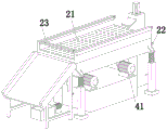
Referring to fig. 1 to 8, the invention provides a feeding device of a metallurgical furnace, comprising a feeding assembly 1, a conveying assembly 2 and a dust suction assembly 3, wherein the feeding assembly 1 is vertically arranged at the side of the conveying assembly 2, the output end of the feeding assembly 1 corresponds to the conveying assembly 2, the conveying assembly 2 comprises a conveying member 21, a cleaning member 22 and a dust removing member 23, the conveying member 21 is vertically arranged, the bottom of the conveying member 21 is provided with an installation table 4, the installation table 4 is provided with two rotating members 41, the output ends of the two rotating members 41 are in transmission fit with the conveying member 21, the cleaning member 22 is arranged on the conveying member 21, the cleaning member 22 is in rotation fit with the conveying member 21, the dust removing member 23 is arranged at the top of the conveying member 21, the dust suction assembly 3 is arranged below the conveying member 21, and the input end of the dust suction assembly 3 is communicated with the conveying member 21, the discharging end of the conveying member 21 is provided with a discharging frame 5.
The feeding assembly 1 comprises a feeding box 11, a feeding motor 12 and a feeding packing auger 15, the feeding box 11 is vertically arranged, a feeding cavity is arranged in the feeding box 11, the feeding motor 12 is arranged at the top of the feeding box 11, the output end of the feeding motor 12 is vertically arranged downwards, the feeding packing auger 15 is arranged in the feeding cavity of the feeding box 11, two ends of the feeding packing auger 15 are respectively rotatably connected with the top and the bottom of the feeding box 11, the top of the feeding packing auger 15 is fixedly connected with the output end of the feeding motor 12, a feeding barrel 13 communicated with the feeding box 11 is arranged at the lower end of the feeding box 11, and a discharging barrel 14 communicated with the feeding box 11 is arranged at the upper end of the feeding box 11; when carrying metallurgical material, carry metallurgical material to the material loading box 11 in through feed cylinder 13, material loading motor 12 work drives material loading auger 15 and rotates, and material loading auger 15 rotates and drives metallurgical material and upwards carry, carries metallurgical material to transport on 21 through play feed cylinder 14.
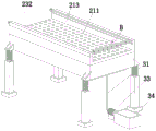
The conveying member 21 comprises a conveying screen plate 211, a conveying plate 212, two partition plates 213 and four supporting seats 214, the four supporting seats 214 are arranged in a rectangular array, the top of each supporting seat 214 is provided with a vibration spring 216, the top of each vibration spring 216 is provided with a connecting block 215, the conveying plate 212 is arranged on the four connecting blocks 215, the conveying plate 212 is provided with a conveying cavity 2141, the conveying screen plate 211 is horizontally arranged on the conveying plate 212, the two partition plates 213 are symmetrically arranged on the top of the conveying screen plate 211, and the bottom of the conveying plate 212 is provided with a collecting cover 217 communicated with the conveying cavity 2141; on carrying metallurgical material to carrying otter board 211, two rotate the piece 41 and rotate and remove the metallurgical material on carrying otter board 211, at the in-process that metallurgical material removed, the effect of vibrations spring 216 plays the effect of connecting and vibrations at the in-process of vibrations, when screening metallurgical material, dust in the metallurgical material will fall into in the transport chamber 2141.
The cleaning part 22 comprises a moving plate 221, a cleaning plate 222, two cleaning motors 223 and two rotating threaded rods 224, the two rotating threaded rods 224 are arranged on the conveying plate 212 and are rotatably connected with the conveying plate 212, the two cleaning motors 223 are arranged on the side wall of the conveying plate 212, one ends of the two rotating threaded rods 224 are respectively and fixedly connected with the conveying ends of the two cleaning motors 223, the moving plate 221 is arranged on the two rotating threaded rods 224 and is respectively and threadedly connected with the two rotating threaded rods 224, threaded holes in threaded fit with the two rotating threaded rods 224 are formed in the moving plate 221, the cleaning plate 222 is vertically arranged at the bottom of the moving plate 221, and the cleaning plate 222 is in sliding fit with the side wall of a conveying cavity 2141 in the conveying plate 212; after the dust enters the conveying cavity 2141, the two cleaning motors 223 work to drive the two rotating threaded rods 224 to rotate on the conveying plate 212, the two rotating threaded rods 224 rotate to drive the moving plate 221 to move, the moving plate 221 moves to drive the cleaning plate 222 to move to clean the dust in the conveying cavity 2141, the dust is conveyed into the collecting cover 217 during cleaning, and the automatic cleaning operation of the dust can be realized by the two cleaning motors 223 working to the bottom and moving the cleaning plate 222.
Each rotating member 41 comprises a rotating motor 411, a rotating base 412 and a cam 413, the rotating motor 411 is arranged at the top of the mounting table 4, the cam 413 is arranged on an output shaft of the rotating motor 411, the rotating base 412 is arranged at the bottom of the conveying plate 212, a rotating wheel 414 is arranged on the rotating base 412, and the rotating wheel 414 is in sliding fit with the cam 413; the work of rotating motor 411 drives cam 413 to rotate, and cam 413 rotates and drives and rotates wheel 414 and rotate on rotating seat 412, and rotating seat 412 moves and drives conveying plate 212 and vibrate on four supporting seats 214 through four vibrations spring 216, carries out the dust removal operation to the dust in the metallurgical material.
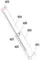
Two symmetrically-arranged lifting pieces 42 are arranged on two sides of the mounting table 4, each lifting piece 42 comprises a first mounting seat 421, a second mounting seat 422, a lifting plate 423 and a telescopic plate 424, the first mounting seat 421 is arranged on the side wall of the mounting table 4, the second mounting seat 422 is arranged at the bottom of the conveying plate 212, the bottom of the lifting plate 423 is hinged to the first mounting seat 421, the telescopic plate 424 is arranged on the lifting plate 423 and is in sliding fit with the lifting plate 423, the top of the telescopic plate 424 is hinged to the second mounting seat 422, a toothed plate 425 is arranged on the telescopic plate 424, a moving motor 426 is arranged on the lifting plate 423, and a rotating gear 427 meshed with the toothed plate 425 is arranged on an output shaft of the moving motor 426; in the screening process, the moving motor 426 works to drive the rotating gear 427 to rotate, the rotating gear 427 rotates to drive the toothed plate 425 to move, the toothed plate 425 moves to drive the telescopic plate 424 to move on the lifting plate 423, and the telescopic plate 424 moves to drive the conveying plate 212 to move, so that the screening operation is performed on the metallurgical materials.
The dust removing part 23 comprises a sliding plate 231 and two lead screw sliding tables 232, the two lead screw sliding tables 232 are symmetrically arranged on two partition plates 213, the sliding plate 231 is horizontally arranged on the sliding blocks of the two lead screw sliding tables 232, the sliding plate 231 is provided with a plurality of exhaust pipes 233 arranged at equal intervals, each exhaust pipe 233 is provided with an air outlet nozzle 234, the top of each exhaust pipe 233 is provided with a connecting pipe 235, and each connecting pipe 235 is provided with an air inlet pipe 236 communicated with the connecting pipe 235; gaseous through intake pipe 236 with gas delivery to connecting pipe 235 on, connecting pipe 235 with gas delivery to a plurality of blast pipes 233 on, the slider of two lead screw slip tables 232 removes and drives sliding plate 231, sliding plate 231 removes and drives a plurality of blast pipes 233 and removes, a plurality of blast pipes 233 drive a plurality of gas outlet nozzle 234 and export the mesh on carrying otter board 211 in with gas, clear up the plug in the mesh, the mesh on carrying otter board 211 after the clearance just can not block up, can not influence the screening operation of carrying otter board 211.
The dust collection assembly 3 comprises a feeding pipe 31, a discharging pipe 32, a dust collection fan 33 and a material collection box 34, the dust collection fan 33 is arranged below the discharging frame 5, two ends of the feeding pipe 31 are respectively communicated with an input end of the dust collection fan 33 and the material collection cover 217, the material collection box 34 is arranged beside the dust collection fan 33, and two ends of the discharging pipe 32 are respectively communicated with an output end of the dust collection fan 33 and the material collection box 34; after the dust is conveyed into the collecting cover 217, the dust suction fan 33 works to suck the dust through the feeding pipe 31, and after the dust is sucked, the dust is conveyed into the collecting box 34 through the discharging pipe 32, and the collecting box 34 stores the dust.
The working principle of the invention is as follows: when the invention is used, when metallurgical materials are conveyed, the metallurgical materials are conveyed into an upper material box 11 through a feeding cylinder 13, a feeding motor 12 works to drive a feeding auger 15 to rotate, the feeding auger 15 rotates to drive the metallurgical materials to be conveyed upwards, the metallurgical materials are conveyed onto a conveying member 21 through a discharging cylinder 14, a rotating motor 411 works to drive a cam 413 to rotate, the cam 413 rotates to drive a rotating wheel 414 to rotate on a rotating seat 412, the rotating seat 412 moves to drive a conveying plate 212 to vibrate on four supporting seats 214 through four vibrating springs 216, dust removal operation is carried out on dust in the metallurgical materials, in the screening process, a moving motor 426 works to drive a rotating gear 427 to rotate, the rotating gear 427 rotates to drive a rotating toothed plate 425 to move, the toothed plate 425 moves to drive a telescopic plate 424 to move on a lifting plate 423, the telescopic plate 424 moves to drive the conveying plate 212 to move, screening operation is carried out on the metallurgical materials, when the metallurgical materials are conveyed to the conveying screen plate 211, the vibration spring 216 plays a role in connection and vibration in the vibration process in the process of moving the metallurgical materials, when the metallurgical materials are screened, dust in the metallurgical materials falls into the conveying cavity 2141, after the dust enters the conveying cavity 2141, the two cleaning motors 223 work to drive the two rotary threaded rods 224 to rotate on the conveying plate 212, the two rotary threaded rods 224 rotate to drive the moving plate 221 to move, the moving plate 221 moves to drive the cleaning plate 222 to move to clean the dust in the conveying cavity 2141, when the dust is cleaned, the dust is conveyed into the collecting cover 217, when the two cleaning motors 223 work to move to the cleaning plate 222, the automatic cleaning operation on the dust can be realized, the gas is conveyed to the connecting pipe 235 through the gas inlet pipe 236, the connecting pipe 235 conveys the gas to the plurality of exhaust pipes 233, the slider of two lead screw slip tables 232 removes and drives sliding plate 231, sliding plate 231 removes and drives a plurality of blast pipes 233 and removes, a plurality of blast pipes 233 drive a plurality of gas outlet nozzle 234 and export the mesh on carrying otter board 211 in, clearance is carried out to the plug in the mesh, the mesh on carrying otter board 211 after the clearance just can not block up, can not influence the screening operation of carrying otter board 211, carry the dust to gathering after in cover 217, dust absorption fan 33 work absorbs the dust through inlet pipe 31, carry the dust to gathering the case 34 in through discharging pipe 32 after absorbing, gathering case 34 and depositing the dust.
Finally, it should be noted that: the above embodiments are only used to illustrate the technical solution of the present invention, and not to limit the same; while the invention has been described in detail and with reference to the foregoing embodiments, it will be understood by those skilled in the art that: the technical solutions described in the foregoing embodiments may still be modified, or some or all of the technical features may be equivalently replaced; and the modifications or the substitutions do not make the essence of the corresponding technical solutions depart from the scope of the technical solutions of the embodiments of the present invention.
Claims (3)
1. A feeding device of a metallurgical furnace comprises a feeding assembly (1), a conveying assembly (2) and a dust collection assembly (3), wherein the feeding assembly (1) is vertically arranged at the side of the conveying assembly (2), the output end of the feeding assembly (1) corresponds to the conveying assembly (2), the conveying assembly (2) comprises a conveying piece (21), a cleaning piece (22) and a dust removal piece (23), the conveying piece (21) is vertically arranged, a mounting table (4) is arranged at the bottom of the conveying piece (21), two rotating pieces (41) are arranged on the mounting table (4), the output ends of the two rotating pieces (41) are in transmission fit with the conveying piece (21), the cleaning piece (22) is arranged on the conveying piece (21), the cleaning piece (22) is in rotation fit with the conveying piece (21), and the dust removal piece (23) is arranged at the top of the conveying piece (21), the dust collection assembly (3) is arranged below the conveying piece (21), the input end of the dust collection assembly (3) is communicated with the conveying piece (21), and the discharge end of the conveying piece (21) is provided with a discharge frame (5);
the method is characterized in that:
the conveying piece (21) comprises a conveying screen plate (211), a conveying plate (212), two partition plates (213) and four supporting seats (214), the four supporting seats (214) are arranged in a rectangular array, a vibration spring (216) is arranged at the top of each supporting seat (214), a connecting block (215) is arranged at the top of each vibration spring (216), the conveying plate (212) is arranged on the four connecting blocks (215), a conveying cavity (2141) is formed in the conveying plate (212), the conveying screen plate (211) is horizontally arranged on the conveying plate (212), the two partition plates (213) are symmetrically arranged at the top of the conveying screen plate (211), and an aggregate cover (217) communicated with the conveying cavity (2141) is arranged at the bottom of the conveying plate (212);
the cleaning piece (22) comprises a moving plate (221), a cleaning plate (222), two cleaning motors (223) and two rotating threaded rods (224), the two rotating threaded rods (224) are arranged on the conveying plate (212) and are rotatably connected with the conveying plate (212), the two cleaning motors (223) are arranged on the side wall of the conveying plate (212), one ends of the two rotating threaded rods (224) are respectively and fixedly connected with the conveying ends of the two cleaning motors (223), the moving plate (221) is arranged on the two rotating threaded rods (224) and is respectively in threaded connection with the two rotating threaded rods (224), the moving plate (221) is provided with threaded holes which are in threaded fit with the two rotating threaded rods (224), the cleaning plate (222) is vertically arranged at the bottom of the moving plate (221), the cleaning plate (222) is in sliding fit with the side wall of the conveying cavity (2141) on the conveying plate (212);
the dust removal part (23) comprises a sliding plate (231) and two lead screw sliding tables (232), the two lead screw sliding tables (232) are symmetrically arranged on the two partition plates (213), the sliding plate (231) is horizontally arranged on the sliding blocks of the two lead screw sliding tables (232), a plurality of exhaust pipes (233) which are arranged at equal intervals are arranged on the sliding plate (231), each exhaust pipe (233) is provided with an air outlet nozzle (234), the top of each exhaust pipe (233) is provided with a connecting pipe (235), and each connecting pipe (235) is provided with an air inlet pipe (236) communicated with the connecting pipe;
each rotating part (41) comprises a rotating motor (411), a rotating seat (412) and a cam (413), the rotating motor (411) is arranged at the top of the mounting table (4), the cam (413) is arranged on an output shaft of the rotating motor (411), the rotating seat (412) is arranged at the bottom of the conveying plate (212), a rotating wheel (414) is arranged on the rotating seat (412), and the rotating wheel (414) is in sliding fit with the cam (413);
two symmetrically arranged lifting pieces (42) are arranged on two sides of the mounting table (4), each lifting piece (42) comprises a first mounting seat (421), a second mounting seat (422), a lifting plate (423) and a telescopic plate (424), the first mounting seat (421) is arranged on the side wall of the mounting table (4), the second mounting seat (422) is arranged at the bottom of the conveying plate (212), the bottom of the lifting plate (423) is hinged with the first mounting seat (421), the expansion plate (424) is arranged on the lifting plate (423) and is in sliding fit with the lifting plate (423), the top of the telescopic plate (424) is hinged with the second mounting seat (422), a toothed plate (425) is arranged on the telescopic plate (424), the lifting plate (423) is provided with a moving motor (426), and an output shaft of the moving motor (426) is provided with a rotating gear (427) meshed with the toothed plate (425).
2. The charging device for a metallurgical furnace according to claim 1, wherein: the material loading subassembly (1) is including last workbin (11), material loading motor (12) and material loading auger (15), it is vertical setting to go up workbin (11), be equipped with the material loading chamber in material loading workbin (11), material loading motor (12) set up the vertical downward setting of output at the top of last workbin (11) and material loading motor (12), material loading auger (15) set up the material loading intracavity at last workbin (11), the both ends of material loading auger (15) rotate with the top and the bottom of last workbin (11) respectively and are connected, the top of material loading auger (15) and the output fixed connection of material loading motor (12), the lower extreme of material loading workbin (11) is equipped with rather than feeding section of thick bamboo (13) that is linked together, the upper end of material loading workbin (11) is equipped with rather than ejection of thick bamboo (14) that is linked together.
3. The charging device for a metallurgical furnace according to claim 1, wherein: dust absorption subassembly (3) include inlet pipe (31), discharging pipe (32), dust absorption fan (33) and collection case (34), dust absorption fan (33) set up the below in play work or material rest (5), the both ends of inlet pipe (31) are linked together with the input of dust absorption fan (33) and the cover (217) that gathers materials respectively, the side of collection case (34) setting at dust absorption fan (33), the both ends of discharging pipe (32) are linked together with the output of dust absorption fan (33) and collection case (34) respectively.
Priority Applications (1)
| Application Number | Priority Date | Filing Date | Title |
|---|---|---|---|
| CN201910770506.3A CN110434060B (en) | 2019-08-20 | 2019-08-20 | Feeding device of metallurgical furnace |
Applications Claiming Priority (1)
| Application Number | Priority Date | Filing Date | Title |
|---|---|---|---|
| CN201910770506.3A CN110434060B (en) | 2019-08-20 | 2019-08-20 | Feeding device of metallurgical furnace |
Publications (2)
| Publication Number | Publication Date |
|---|---|
| CN110434060A CN110434060A (en) | 2019-11-12 |
| CN110434060B true CN110434060B (en) | 2021-12-31 |
Family
ID=68436689
Family Applications (1)
| Application Number | Title | Priority Date | Filing Date |
|---|---|---|---|
| CN201910770506.3A Active CN110434060B (en) | 2019-08-20 | 2019-08-20 | Feeding device of metallurgical furnace |
Country Status (1)
| Country | Link |
|---|---|
| CN (1) | CN110434060B (en) |
Families Citing this family (5)
| Publication number | Priority date | Publication date | Assignee | Title |
|---|---|---|---|---|
| CN111515022A (en) * | 2020-05-08 | 2020-08-11 | 过蕊 | Garbage disposal equipment |
| CN111715534A (en) * | 2020-07-01 | 2020-09-29 | 合肥学院 | Intelligent garbage recognition and classification device |
| CN112474322B (en) * | 2020-10-23 | 2022-05-13 | 无锡耐斯利胶基制造有限公司 | Vibrating screen material distributor for gum base production line |
| CN112919027A (en) * | 2021-03-23 | 2021-06-08 | 刘俊宝 | Spiral conveyer |
| CN113172834B (en) * | 2021-05-12 | 2023-05-12 | 台州市卓信塑业有限公司 | Dustproof impurity removal device of tripper |
Citations (4)
| Publication number | Priority date | Publication date | Assignee | Title |
|---|---|---|---|---|
| CN108097581A (en) * | 2018-02-10 | 2018-06-01 | 张炳强 | A kind of building sand-gravel separation device that deslagging is adjusted based on screw |
| CN207756493U (en) * | 2017-10-31 | 2018-08-24 | 新昌县城南乡量创机械厂 | A kind of soybean planting seed cleaning equipment |
| CN108636761A (en) * | 2018-04-12 | 2018-10-12 | 江苏景泰玻璃有限公司 | A kind of quartz sand automatic splinter screening device for screening |
| CN208944595U (en) * | 2018-07-27 | 2019-06-07 | 刘新房 | A kind of discharging dust-extraction unit of agricultural wheat harvester |
-
2019
- 2019-08-20 CN CN201910770506.3A patent/CN110434060B/en active Active
Patent Citations (4)
| Publication number | Priority date | Publication date | Assignee | Title |
|---|---|---|---|---|
| CN207756493U (en) * | 2017-10-31 | 2018-08-24 | 新昌县城南乡量创机械厂 | A kind of soybean planting seed cleaning equipment |
| CN108097581A (en) * | 2018-02-10 | 2018-06-01 | 张炳强 | A kind of building sand-gravel separation device that deslagging is adjusted based on screw |
| CN108636761A (en) * | 2018-04-12 | 2018-10-12 | 江苏景泰玻璃有限公司 | A kind of quartz sand automatic splinter screening device for screening |
| CN208944595U (en) * | 2018-07-27 | 2019-06-07 | 刘新房 | A kind of discharging dust-extraction unit of agricultural wheat harvester |
Also Published As
| Publication number | Publication date |
|---|---|
| CN110434060A (en) | 2019-11-12 |
Similar Documents
| Publication | Publication Date | Title |
|---|---|---|
| CN110434060B (en) | Feeding device of metallurgical furnace | |
| CN210995190U (en) | Be used for grain production to remove dust device | |
| CN115870056B (en) | Multistage grinding equipment for silicon micropowder production | |
| CN111804593A (en) | Gumming device is used in production of dry-type machine-made sand | |
| CN108637190A (en) | A kind of automobile core shooter sanding device | |
| CN211437025U (en) | Pulse type environment-friendly cleaning sieve | |
| CN216856998U (en) | Fine solid powder coating vibration filtering device | |
| CN113680429B (en) | Graphene particle material treatment process | |
| CN112452719B (en) | Silicon carbide classifying and screening device | |
| CN213001090U (en) | Multilayer vibration screening machine | |
| CN212141820U (en) | Pulse type bag dust collector | |
| CN114833062A (en) | Sorting unit is used in artificial diamond production | |
| CN209006185U (en) | A kind of molecular sieve production exclusion device | |
| CN218743102U (en) | Dross removal mechanism for rice production | |
| CN219188084U (en) | Ash removal equipment | |
| CN218424034U (en) | Rice grading and refining device | |
| CN217314364U (en) | Dustproof multistage mechanical screening device | |
| CN220258149U (en) | Silicon micropowder impurity removing equipment convenient to clean | |
| CN218965126U (en) | Sand material recovery device of sand blasting machine | |
| CN219807485U (en) | Long-distance carbon microsphere powder conveying, sieving and sorting comprehensive equipment | |
| CN219334946U (en) | Gangue raw material screening machine | |
| CN219805028U (en) | Dust collector of powder metallurgy | |
| CN215235793U (en) | Impurity filtering and screening device for machining | |
| CN220444346U (en) | Building material screening plant | |
| CN217017414U (en) | Quartz sand particle screening device |
Legal Events
| Date | Code | Title | Description |
|---|---|---|---|
| PB01 | Publication | ||
| PB01 | Publication | ||
| SE01 | Entry into force of request for substantive examination | ||
| SE01 | Entry into force of request for substantive examination | ||
| TA01 | Transfer of patent application right |
Effective date of registration: 20211216 Address after: 755000 luojinxin Industrial Park, Shapotou District, Zhongwei City, Ningxia Hui Autonomous Region Applicant after: Ningxia Zhongwei Yinhe smelting Co.,Ltd. Address before: 239200 No. 95 Anle lane, Xin'an Town, Lai'an county, Chuzhou City, Anhui Province Applicant before: Zhao Jian |
|
| TA01 | Transfer of patent application right | ||
| GR01 | Patent grant | ||
| GR01 | Patent grant |