CN110420066B - Bone implant and implant abutment - Google Patents
Bone implant and implant abutment Download PDFInfo
- Publication number
- CN110420066B CN110420066B CN201910605983.4A CN201910605983A CN110420066B CN 110420066 B CN110420066 B CN 110420066B CN 201910605983 A CN201910605983 A CN 201910605983A CN 110420066 B CN110420066 B CN 110420066B
- Authority
- CN
- China
- Prior art keywords
- implant
- proximal
- thread
- distal
- abutment
- Prior art date
- Legal status (The legal status is an assumption and is not a legal conclusion. Google has not performed a legal analysis and makes no representation as to the accuracy of the status listed.)
- Active
Links
Images


Classifications
-
- A—HUMAN NECESSITIES
- A61—MEDICAL OR VETERINARY SCIENCE; HYGIENE
- A61C—DENTISTRY; APPARATUS OR METHODS FOR ORAL OR DENTAL HYGIENE
- A61C8/00—Means to be fixed to the jaw-bone for consolidating natural teeth or for fixing dental prostheses thereon; Dental implants; Implanting tools
-
- A—HUMAN NECESSITIES
- A61—MEDICAL OR VETERINARY SCIENCE; HYGIENE
- A61C—DENTISTRY; APPARATUS OR METHODS FOR ORAL OR DENTAL HYGIENE
- A61C3/00—Dental tools or instruments
-
- A—HUMAN NECESSITIES
- A61—MEDICAL OR VETERINARY SCIENCE; HYGIENE
- A61C—DENTISTRY; APPARATUS OR METHODS FOR ORAL OR DENTAL HYGIENE
- A61C8/00—Means to be fixed to the jaw-bone for consolidating natural teeth or for fixing dental prostheses thereon; Dental implants; Implanting tools
- A61C8/0018—Means to be fixed to the jaw-bone for consolidating natural teeth or for fixing dental prostheses thereon; Dental implants; Implanting tools characterised by the shape
- A61C8/0022—Self-screwing
-
- A—HUMAN NECESSITIES
- A61—MEDICAL OR VETERINARY SCIENCE; HYGIENE
- A61C—DENTISTRY; APPARATUS OR METHODS FOR ORAL OR DENTAL HYGIENE
- A61C8/00—Means to be fixed to the jaw-bone for consolidating natural teeth or for fixing dental prostheses thereon; Dental implants; Implanting tools
- A61C8/0048—Connecting the upper structure to the implant, e.g. bridging bars
- A61C8/005—Connecting devices for joining an upper structure with an implant member, e.g. spacers
- A61C8/0056—Connecting devices for joining an upper structure with an implant member, e.g. spacers diverging in the apical direction of the implant or abutment
-
- A—HUMAN NECESSITIES
- A61—MEDICAL OR VETERINARY SCIENCE; HYGIENE
- A61C—DENTISTRY; APPARATUS OR METHODS FOR ORAL OR DENTAL HYGIENE
- A61C8/00—Means to be fixed to the jaw-bone for consolidating natural teeth or for fixing dental prostheses thereon; Dental implants; Implanting tools
- A61C8/0048—Connecting the upper structure to the implant, e.g. bridging bars
- A61C8/005—Connecting devices for joining an upper structure with an implant member, e.g. spacers
- A61C8/0059—Connecting devices for joining an upper structure with an implant member, e.g. spacers with additional friction enhancing means
-
- A—HUMAN NECESSITIES
- A61—MEDICAL OR VETERINARY SCIENCE; HYGIENE
- A61C—DENTISTRY; APPARATUS OR METHODS FOR ORAL OR DENTAL HYGIENE
- A61C8/00—Means to be fixed to the jaw-bone for consolidating natural teeth or for fixing dental prostheses thereon; Dental implants; Implanting tools
- A61C8/0048—Connecting the upper structure to the implant, e.g. bridging bars
- A61C8/005—Connecting devices for joining an upper structure with an implant member, e.g. spacers
- A61C8/006—Connecting devices for joining an upper structure with an implant member, e.g. spacers with polygonal positional means, e.g. hexagonal or octagonal
-
- A—HUMAN NECESSITIES
- A61—MEDICAL OR VETERINARY SCIENCE; HYGIENE
- A61C—DENTISTRY; APPARATUS OR METHODS FOR ORAL OR DENTAL HYGIENE
- A61C8/00—Means to be fixed to the jaw-bone for consolidating natural teeth or for fixing dental prostheses thereon; Dental implants; Implanting tools
- A61C8/0048—Connecting the upper structure to the implant, e.g. bridging bars
- A61C8/005—Connecting devices for joining an upper structure with an implant member, e.g. spacers
- A61C8/0068—Connecting devices for joining an upper structure with an implant member, e.g. spacers with an additional screw
-
- A—HUMAN NECESSITIES
- A61—MEDICAL OR VETERINARY SCIENCE; HYGIENE
- A61C—DENTISTRY; APPARATUS OR METHODS FOR ORAL OR DENTAL HYGIENE
- A61C8/00—Means to be fixed to the jaw-bone for consolidating natural teeth or for fixing dental prostheses thereon; Dental implants; Implanting tools
- A61C8/0048—Connecting the upper structure to the implant, e.g. bridging bars
- A61C8/005—Connecting devices for joining an upper structure with an implant member, e.g. spacers
- A61C8/0069—Connecting devices for joining an upper structure with an implant member, e.g. spacers tapered or conical connection
-
- A—HUMAN NECESSITIES
- A61—MEDICAL OR VETERINARY SCIENCE; HYGIENE
- A61C—DENTISTRY; APPARATUS OR METHODS FOR ORAL OR DENTAL HYGIENE
- A61C8/00—Means to be fixed to the jaw-bone for consolidating natural teeth or for fixing dental prostheses thereon; Dental implants; Implanting tools
- A61C8/0048—Connecting the upper structure to the implant, e.g. bridging bars
- A61C8/005—Connecting devices for joining an upper structure with an implant member, e.g. spacers
- A61C8/0074—Connecting devices for joining an upper structure with an implant member, e.g. spacers with external threads
-
- A—HUMAN NECESSITIES
- A61—MEDICAL OR VETERINARY SCIENCE; HYGIENE
- A61C—DENTISTRY; APPARATUS OR METHODS FOR ORAL OR DENTAL HYGIENE
- A61C8/00—Means to be fixed to the jaw-bone for consolidating natural teeth or for fixing dental prostheses thereon; Dental implants; Implanting tools
- A61C8/0048—Connecting the upper structure to the implant, e.g. bridging bars
- A61C8/0075—Implant heads specially designed for receiving an upper structure
-
- A—HUMAN NECESSITIES
- A61—MEDICAL OR VETERINARY SCIENCE; HYGIENE
- A61C—DENTISTRY; APPARATUS OR METHODS FOR ORAL OR DENTAL HYGIENE
- A61C8/00—Means to be fixed to the jaw-bone for consolidating natural teeth or for fixing dental prostheses thereon; Dental implants; Implanting tools
- A61C8/0048—Connecting the upper structure to the implant, e.g. bridging bars
- A61C8/0078—Connecting the upper structure to the implant, e.g. bridging bars with platform switching, i.e. platform between implant and abutment
-
- A—HUMAN NECESSITIES
- A61—MEDICAL OR VETERINARY SCIENCE; HYGIENE
- A61C—DENTISTRY; APPARATUS OR METHODS FOR ORAL OR DENTAL HYGIENE
- A61C8/00—Means to be fixed to the jaw-bone for consolidating natural teeth or for fixing dental prostheses thereon; Dental implants; Implanting tools
- A61C8/008—Healing caps or the like
-
- A—HUMAN NECESSITIES
- A61—MEDICAL OR VETERINARY SCIENCE; HYGIENE
- A61C—DENTISTRY; APPARATUS OR METHODS FOR ORAL OR DENTAL HYGIENE
- A61C8/00—Means to be fixed to the jaw-bone for consolidating natural teeth or for fixing dental prostheses thereon; Dental implants; Implanting tools
- A61C8/0089—Implanting tools or instruments
Abstract
The invention relates to a bone implant and an implant abutment. And more particularly to a dental implant in the form of a screw for implantation into bone. The bone implant is configured as a self-drilling bone implant that is good at compressing, collecting and distributing bone along all surfaces of the implant and within the implantation site to significantly increase the contact surface of the bone implant. The implant is configured to have a coronal portion and a body portion that are continuous with one another. The crown portion is configured to have an overall diameter that is less than an overall diameter of the body portion. The body portion is adapted with threads that promote self-drilling and bone-harvesting performance when the implant is rotated in both a clockwise and counter-clockwise direction.
Description
This application is a divisional application, the parent application of which has application number 201580018390.8 (international application number PCT/IL2015/050139), application date 2015, 2, month 5, entitled "dental implant for collecting and distributing bone".
Technical Field
The present invention relates to an endosseous implant and an implant abutment, and in particular, to a screw-form dental implant for implantation into bone.
Background
A dental implant is provided to replace a missing tooth in the oral cavity. The dental implant comprises various parts which together form a structure replacing the tooth, achieving aesthetic and functional purposes.
Dental implants typically comprise a crown portion replacing the crown portion of the missing tooth, and an implant replacing the root of the missing tooth, wherein the crown and implant are coupled to each other by an implant abutment (abutment). All three parts work together to allow a successful implantation procedure. The implant provides the main base and support structure for the implantation and is therefore the central element for successful dental implantation.
Dental implants are provided, typically in the form of a screw, generally comprising a head portion and a body portion. The head portion defines a coronal section of the implant for facilitating machining and coupling with other implant structures (e.g., abutments and crowns). The body portion defines a top section of the implant for integration with bone to allow osseointegration to occur.
The implant body portion has various designs that are designed according to a number of parameters, including the type of bone to be implanted, the location where the implant is to be made (the implantation site). The body portion includes threads along its length for securely introducing the implant into and integrating the implant with the bone.
Despite advances in implant design, there is a continuing need for improved osseointegration capabilities of dental implants, which in turn will result in improved implant stability and longevity.
Disclosure of Invention
The present invention relates to intra-osseous implants and in particular to dental implants in the form of screws for implantation into bone.
Embodiments of the present invention provide a self-drilling dental implant configured to facilitate insertion and osseointegration by compressing, collecting and distributing bone along all surfaces of the implant. Preferably, the collecting and dispensing is performed while rotating the implant in a clockwise or counterclockwise direction. Aspects of the invention can be implemented to reconfigure the implantation of all forms of dental implants in any area of the upper and lower jaws.
Alternatively, the dental implant of the invention can be configured as a molar implant replacing teeth in the molar region of the upper and/or lower jaw.
The dental implant according to an embodiment of the present invention is a self-drilling, self-tapping, self-collecting bone and bone compression type dental implant. The implant according to the embodiment of the present invention may be used for a healing site after bone growth or may be used for an extraction site.
Most preferably, the implant according to the present invention is configured to collect and/or distribute bone along all its surfaces, thereby increasing bone implant contact ('BIC') therein, improving the osseointegration process.
Preferably, embodiments of the present invention allow for cutting, mixing and guiding of bone within the implantation site.
Preferably, the implant according to the invention can be used as a self-drilling implant to facilitate implantation in an extraction site slot and/or a cavity within a bone structure, or a healing side extraction site.
Optionally and preferably, introducing the implant into the extraction site slot allows the physician to optimally hold the dural plate at the extraction site while allowing the implant to engage and/or integrate with at least a portion of the dural plate. This optimal retention of the dural plate significantly improves the overall healing period.
Preferably, an implant according to an alternative embodiment of the present invention provides an implant for use as an instrument for first distributing bone in all directions by accumulating bone along the surface of the implant. Similarly, bone material may be introduced into different locations within the implantation site by manipulating the implant in a clockwise direction and/or a counter-clockwise direction. This manipulation of the implant provides a directional bone in either the superior (coronal) or inferior (apical) portions of the implant.
Embodiments of the present invention further provide for introducing bone material and/or graft material into the implantation site through the coronal opening of the sulcus before and/or after integrating the implant in the mandible or maxilla.
Embodiments of the present invention provide a dental implant that facilitates the collection of any bone from at least one of an extraction site membrane, bone graft material, and the like at an implantation site.
Embodiments of the present invention provide an implant that is self-drilling in the interior, which is capable of selectively expanding bone at the site of implantation to create more space within and around the implant for receiving bone, thereby improving osseointegration and improving the formation of the initial matrix formed for osseointegration.
Embodiments of the present invention provide a coronal portion having a smaller overall diameter that facilitates the accommodation of more bone within and around the coronal portion.
Preferably, the configuration of the coronal portion having an overall diameter less than the main body portion allows for pressure equalization, wherein the pressure on the implant may be evenly distributed along the length of the implant at the implantation site. This is a function of the coronal portion of the implant being associated with compact and/or dense cortical bone while the main portion is associated with less dense porous bone. Thus, according to an alternative embodiment of the present invention, having a smaller coronal portion and a wider body portion balances the compressive forces along the length of the implant after implantation. Such pressure equalization may delay, reduce, and/or prevent bone resorption due to an imbalance in the pressure distribution across the implant. The pressure equalization allows the implant to control and/or adjust the fixation torque according to the implant threads, which are configured to facilitate cutting, tapping and collecting bone when manipulated in both clockwise and counterclockwise directions. Alternative embodiments allow both the body portion threads and the crown portion threads to be cutting threads that allow control of pressure along the length of the implant and manipulation of bone material around any portion of the implant.
Embodiments of the present invention provide a coronal portion comprising a plurality (at least three or four) of dental implant prosthesis attachment platforms.
Embodiments of the present invention provide a self-drilling implant that can facilitate changing the direction of implantation during implantation. This directional control of the implant due to the self-drilling thread allows the physician to freely manipulate the implant within the bone as required by the clinical situation at the time. In particular, a physician may use the implant according to the invention to expand the bone in the buccal direction, and thus may position the implant in a clinically desirable position. Such directional control allows control of the angle and/or direction of insertion of the implant.
Embodiments of the present invention, and in particular the ability of the implant to cut and distribute bone during rotation in both clockwise and counterclockwise directions, control the manipulation and movement of bone within the implant site, which further allows the clinician to expedite the sinus lift process. Preferably, the implant is manipulated (rotated) as needed to distribute and compress the bone toward the apex, which allows for enhanced bone growth in and around the apex of the implant.
Alternatively, an implant according to an alternative embodiment may be used to puncture the sinus floor to allow bone to be introduced into the apex to promote sinus lift bone formation.
Embodiments of the present invention provide a dental implant comprising a crown portion and a body portion, wherein the overall diameter of the crown portion is smaller than the overall diameter of the body portion. The implant is characterized in that the coronal portion provides at least three attachment platforms for the implant. Most preferably, the crown portion may be constituted by three substantially cylindrical and/or cylindrical segments, consecutive to each other.
Alternatively, at least one segment of the crown portion may comprise a trapezoidal cross-sectional profile. Optionally and preferably, each of the three sections comprises a trapezoidal cross-sectional profile.
Alternatively, at least one section of the coronal portion may comprise a cylindrical cross-sectional profile.
Embodiments of the present invention provide a dental implant comprising a crown portion and a body portion, wherein the overall diameter of the crown portion is less than the overall diameter of the body portion, wherein the implant is characterized in that the crown portion is configurable to facilitate removal and/or resection from the implant body.
Alternatively, the coronal section may be configured to be removable after placement of the implant. Alternatively, the coronal section may be configured to be removable after placement of the implant following bone resorption.
Optionally, the crown section may be configured at least along a distal portion of the crown section to facilitate removal of the crown section.
Embodiments of the present invention provide a special tool for filing and/or removing a coronal section of a dental implant, the device having:
a dental machining connection interface for coupling with a dental handpiece tool;
a disc-shaped working surface having at least one surface and/or edge that can be coated with a corrosive medium for cutting and/or filing at least a portion of a coronal section of a dental implant;
an implant interface portion for insertion into a central bore of a dental implant, the interface portion comprising: a central body portion for fitting within a central bore recess of an implant; an annular portion for allowing the tool to freely rotate while associated with the implant bore; a distal cap for securely associating a tool with at least a portion of the bore portion and for sealing the implant bore.
Embodiments of the present invention provide a special tool for filing and/or facilitating removal of a coronal section of an implanted dental implant, the device having:
a dental machining connection interface for coupling with a dental handpiece tool;
a cylindrical tool body functionally coupled with the dental tool interface and configured to rotate when activated with the dental handpiece tool; said cylindrical machining body having at least one machining surface and/or edge coated with a medium for cutting and/or filing at least a part of the coronal portion of the dental implant; and
a machining stop interface portion for limiting advancement of the cylindrical body along the coronal section of the implant.
Embodiments of the present invention provide a method for treating bone resorption of an implanted dental implant after dental implantation, the method comprising: exposing, cleaning and separating a coronal section of an implanted implant; associating a coronal removal tool according to an alternative embodiment of the present invention; filing the coronal section of the implant to a desired height relative to the bone surface; and coupling the new implant abutment with the dental implant.
Alternatively, a new implant abutment may be coupled to the implant using a set screw.
Embodiments of the present invention provide a method for treating bone resorption after dental implantation, the method comprising: exposing, cleaning and separating the coronal section along an outer surface of the coronal section of the implanted implant, wherein the outer surface is configured and/or prepared for coupling with an abutment.
Optionally, the outer surface of the crown section is threaded to mate with threads provided along the surface of the abutment. Alternatively, the abutment can be configured to be placed over and/or coupled along the externally threaded crown section, wherein the abutment is configured to have threads corresponding to the threads of the crown section.
Alternatively, an abutment may be associated with an outer surface of the coronal section, wherein the abutment is coupled to the implant with a set screw.
Optionally, after exposing the coronal portion, the coronal portion can be treated to facilitate coupling between the abutment and the treated coronal portion.
Alternatively, the crown portion may be re-threaded on the outer surface of the crown section.
Alternatively, the outer surface of the coronal portion can be reconfigured using a specialized tool to facilitate receiving and/or coupling with the abutment.
Embodiments of the invention provide a bone implant anchor comprising a crown portion and a body portion that are continuous with one another, wherein the crown portion defines a proximal end of the implant anchor and the body portion defines a distal end of the implant anchor, and the body portion has an inner core adapted with threads extending therefrom along a length thereof; the inner core defines an inner diameter of the body portion and the threads define an outer diameter of the body portion, and the crown portion is characterized by at least one or more concave grooves along its outer surface. Preferably, the concave recess is used to promote osseointegration.
Alternatively, the outer section of the crown portion may have threads configured for engagement and/or coupling with an abutment.
Embodiments of the invention provide a bone implant anchor comprising a crown portion and a body portion that are continuous with one another, wherein the crown portion defines a proximal end of the implant anchor, the body portion defines a distal end of the implant anchor, and the body portion has an inner core adapted with threads extending therefrom along a length thereof; the inner core defines an inner diameter of the body portion and the threads define an outer diameter of the body portion, and the crown portion is characterized by a functional cutting thread disposed along an outer surface of the crown portion for cutting into cortical bone. Optionally, the threads of the coronal portion are configured for cutting, compressing, collecting and distributing bone along an outer surface of the coronal portion.
Alternatively, the threads of the control portion may be configured to cut, compress, collect, and distribute bone along the outer surface of the coronal portion, wherein the implant is rotated in at least one of a clockwise direction and/or a counter-clockwise direction. Alternatively, the coronal section of the implant can be configured to cut, compress, collect, and distribute bone when rotated in both a clockwise direction and a counter-clockwise direction.
Embodiments of the present invention provide a dental implant comprising a crown portion and a body portion, wherein the overall diameter of the crown portion is smaller than the overall diameter of the body portion. The implant is characterized in that the body portion includes a core having a thread extending therefrom, the thread defining an outer diameter of the body portion and the core defining an inner diameter of the body portion. Most preferably, the core comprises at least two or more substantially cylindrical and/or cylindrical sections that are fluent in one another.
Alternatively, the core may comprise a plurality of substantially cylindrical subsections, the subsections being fluent in one another.
Alternatively, each subsection defining the implant core may have a cylindrical profile or a trapezoidal profile.
Alternatively, the core may comprise a plurality of substantially cylindrical subsections which are fluent in one another.
Embodiments of the present invention provide a dental implant comprising a crown portion and a body portion, wherein the overall diameter of the crown portion is smaller than the overall diameter of the body portion. The implant is characterized in that the body portion includes a thread along its length and at least two grooves spanning the entire length of the body portion.
Optionally and preferably, the channel is configured to have a proximal opening adjacent to the coronal portion of the implant. Most preferably, the groove may be provided along the length of the thread extending from the core of the body portion. Thus, the groove at least divides the thread into thread sub-sections having a blade and/or wing configuration.
Preferably, the groove comprises an ovoid configuration adjacent the core of the body and a neck portion adjacent the threaded lateral edge and/or the threaded face. Alternatively and preferably, the oval configuration collects bone debris and the neck portion provides at least two cutting bevels. Preferably, the grooves are configured to allow collection and cutting of bone when the implant is rotated in either a clockwise or counterclockwise direction.
Alternatively and preferably, the groove may provide and facilitate osseointegration as the groove of the present invention provides at least one or more of, or any combination thereof, collection of bone, compression of bone, introduction of bone, removal of additional bone, and the like.
Most preferably, the grooves and threads combine to facilitate implant insertion and integration by cutting, trapping, compressing, and distributing bone along the surface of the implant (e.g., including, but not limited to, within the groove recesses, along the threads, between the threads, etc.). Most preferably, the grooves improve the stability of the implant at the implantation site by increasing bone implant contact ('BIC'), thereby providing a matrix therein that promotes osteointegration.
Embodiments of the present invention provide an implant abutment having: a proximal end for interfacing with a restorative structure; a distal end for interfacing with an implant; and an intermediate portion disposed between the proximal end and the distal end; wherein the intermediate portion comprises at least one connection platform coupling surface adapted to interface with at least one connection platform of the implant coronal section. The connection platform surface is selected from the group including, for example and without limitation: a surface having an angle of about 3 degrees and up to about 50 degrees;
a surface having an angle of up to about 70 degrees relative to a surface extending substantially perpendicular to a central axis of the abutment core; a surface substantially perpendicular to a central axis of the abutment core;
adapting the threaded surface to allow coupling with the coronal section by threads corresponding to threads provided along an outer surface of the coronal section of the implant; and any combination thereof.
Embodiments of the invention provide a bone implant anchor comprising a crown portion and a body portion that are continuous with one another, wherein the crown portion defines a proximal end of the implant anchor, the body portion defines a distal end of the implant anchor, and the body portion has an inner core adapted with at least one thread extending therefrom along a length thereof; the inner core defining an inner diameter of the body portion, the at least one thread defining an outer diameter of the body portion; the thread defines a horizontal plane defined along a horizontal plane of the implant, the thread horizontal plane having a first axis along a medial-lateral axis between along a length of the thread and a second axis along an anterior-posterior axis extending around the implant core, the thread comprising: a apical side, a coronal side, and lateral edges connecting the apical and coronal sides, a base connecting the thread to the core, a thread depth (along the medial-lateral axis) defined between the lateral edges and the base; wherein adjacent threads defined between adjacent thread bases are connected over an outer surface of the implant core defining an inter-thread face; the at least one or more threads are characterized by: at least one of the threaded apical surface, the threaded coronal surface, or the lateral edges is adapted with at least one contour modification along a horizontal plane therein, thereby defining at least two subsections along the horizontal plane and along at least one of the medial-lateral axis or the anteroposterior axis.
Optionally, the thread may further comprise at least one or more profile modifications along both axes of the horizontal plane.
Alternatively, the shape modification may be symmetrical about a horizontal plane.
Alternatively, the shape modification may be asymmetric about the horizontal plane.
Alternatively, the thread may be fitted with a plurality of concave recesses. Alternatively, the thread may be adapted with a plurality of extensions.
Embodiments of the present invention provide dental implants having an internal connection platform bore configured to receive a universal implant abutment. The internal connection platform is a bore extending from a proximal end of the implant bore into a medial portion of the implant body. The internal connection platform is preferably centered along the diameter of the implant core. The implant connection platform includes a distal portion, a medial portion, and a proximal portion that are fluidly and continuously connected to one another, wherein the connection platform is characterized by the proximal portion including a generally conical profile.
Most preferably, the attachment platform is further characterized in that it includes at least two anti-rotation interfaces, a first anti-rotation interface disposed along the medial portion and a second anti-rotation interface disposed along the proximal portion adjacent the proximal end of the implant.
Preferably, the distal portion is a substantially cylindrical bore having threads for coupling with a set screw, as is known in the art.
Preferably, the intermediate portion defines an anti-rotation interface in the form of an anti-rotation machining interface for manipulating the implant with a tool. Alternatively, the intermediate portion anti-rotation connection interface may be any anti-rotation machining interface known in the art, including, but not limited to, at least one or more or any combination thereof selected from the group consisting of: such as an inner six-receptor socket, scalloped, inner dodecagon, outer dodecagon, inner hexagon, outer octagon, inner octagon, outer spline, inner spline, morse taper, inner morse taper, unibody, inner six lobes, outer six lobes, inner three lobes, outer three lobes, inner six splines, outer six splines, internal threads, internal pentagon, external threads, internal square, external square, internal five lobes, internal four lobes, internal three splines, external triangle, internal eight splines, external six lobes, internal eight lobes, internal tube and tube insert, triangle, polygon comprising n sides (where n > 3 or more), and the like, as known in the art.
Most preferably, the proximal portion is provided in the form of a substantially conical bore, the diameter of the distal end of the bore adjacent the intermediate portion being smaller and the diameter of the proximal end of the bore defined at the proximal end of the implant being larger.
Optionally and preferably, the conical bore defines a wall that is uniformly angled and/or sloped along the length of the proximal portion from the distal end to the proximal end.
Alternatively, the conical bore may define a wall that is provided with at least two angles and/or slopes along the length of the proximal portion from the distal end to the proximal end, defining therein two proximal portion conical subsections that are continuous and fluent with respect to one another. Preferably, the first sub-section is provided with a first angle and/or inclination and the second sub-section is provided with a second angle and/or inclination, characterised in that the second angle and/or inclination is greater than the first angle and/or inclination with respect to the common mid-line plane.
Most preferably, the proximal portion is fitted with a second anti-rotation interface adjacent to the proximal end of the proximal portion. Most preferably, the second anti-rotation interface is disposed along a conical bore surface and/or wall. Preferably, the second anti-rotation interface retains the entire conical surface of the proximal portion. Most preferably, the second anti-rotation interface is provided in the form of a plurality of recesses distributed along the wall of the proximal portion adjacent the proximal end. Alternatively, the depressions may be configured to be horizontal or longitudinal along the walls of the conical surface. Alternatively and preferably, the second anti-rotation interface may be provided as a plurality of interdigitated recesses distributed along the conical bore surface and/or wall.
Alternatively, the second anti-rotation interface may be provided with at least two or more interdigitated recesses.
Optionally, the internal connection platform bore may further have a circumferential recess and/or groove along at least one of the intermediate portion and/or the proximal portion.
Alternatively, the proximal portion may be adapted with circumferential recesses and/or grooves along the distal end adjacent and/or abutting the distal portion. Alternatively, the circumferential recess may be configured to receive an O-ring for facilitating sealing and/or secure coupling with an alternative dental structure (e.g., including but not limited to an abutment, a healing cap, an impression coping abutment, a measurement abutment, a tool, etc.).
Alternatively, the intermediate portion may be adapted with circumferential recesses and/or grooves along its distal end adjacent and/or abutting the distal portion. Alternatively, the circumferential recess may be configured to receive an O-ring for facilitating sealing and/or secure coupling with an alternative dental structure (e.g., including but not limited to an abutment, a healing cap, an impression coping abutment, a measurement abutment, a tool, etc.).
Optionally, the intermediate portion may be adapted with at least one or more recesses and/or grooves along its distal end adjacent and/or abutting the distal portion.
Embodiments of the present invention provide a dental implant abutment having an implant interface section and a crown interface section. The abutment is characterized in that the implant interface section is configured as a universal abutment interface capable of fitting a variety of dental implants of various diameters and/or sizes. The abutment is further characterized in that the implant interface section includes at least one anti-rotation connection, namely a first anti-rotation connection disposed along a distal portion of the implant interface section.
The implant interface section of the abutment comprises a distal portion and a proximal portion, the distal portion being provided in the form of an anti-rotation interface for mating with an anti-rotation interface of the implant.
Alternatively, the abutment can include at least two anti-rotation connection platforms, a first anti-rotation connection platform disposed along a distal portion of the implant interface section and a second anti-rotation connection platform disposed along a proximal portion of the implant interface section. Alternatively, at least one of the two anti-rotation connection platforms may be provided in the form of an interdigitated connector. Alternatively, both anti-rotation attachment platforms may be provided in the form of interdigitated connectors.
Alternatively, the distal portion of the anti-rotation interface may be adapted with a snap-fit male connector (e.g., including but not limited to cogs and/or flanges and/or extensions, or the like or any combination thereof). Most preferably, a snap-fit male connector is provided for mating and securely coupling with a corresponding female connector and/or recess provided along the implant connection platform.
The abutment is characterized in that a proximal portion of the implant interface section of the abutment has an outer surface with a conical profile, the conical profile being widest at its proximal end adjacent and/or abutting the coronal interface section of the abutment and configured to be narrowest adjacent and/or abutting a distal portion of the implant interface section of the abutment.
Optionally and preferably, the conical outer surface of the proximal portion defines a wall that is provided with a uniform angle and/or slope along the length of the proximal portion of the implant interface section of the abutment.
Optionally, the conical outer surface of the proximal portion defines a wall provided with at least two angles and/or slopes along the length of the proximal portion, defining therein two proximal portion subsections which are conical and continuous with each other. Preferably, the first sub-section is provided with a first angle and/or inclination and the second sub-section is provided with a second angle and/or inclination, characterised in that the second angle and/or inclination is greater than the first angle and/or inclination with respect to the common mid-line plane.
Optionally, the abutment includes a central bore configured to receive a set screw, as is known in the art.
Alternatively, the abutment may have an integral set screw portion disposed distally of the implant interface section. Preferably, the integral set screw portion is configured for coupling with the implant along a threaded bore of the implant.
Embodiments of the present invention provide a dedicated dental tool for associating and manipulating and/or machining and/or manipulating a dental implant according to embodiments of the present invention, the device having: a dental machining connection interface for coupling with a dental handpiece tool, the dental handpiece tool being operable to rotate a dental implant associated with the dental handpiece tool; a working body including a proximal portion, a medial portion, and a distal portion, the proximal portion disposed distal to and continuous with the working connection, the proximal portion defining a conical body having a proximal end and a distal end, the proximal end configured to be wider than the distal end; an intermediate portion disposed distal to and fluidly from the proximal portion, the intermediate portion being provided in the form of an anti-rotation interface, including, but not limited to, a hexagonal profile, for example; the distal portion is disposed distal to and fluidly from the intermediate portion, and the distal portion is preferably configured with a body configured with a diameter smaller than a diameter of the intermediate portion to allow access to the dental implant bore.
Optionally, the intermediate portion is substantially cylindrical.
Alternatively, the dental implant insertion tool may be configured with a hollow flow passage along its length to facilitate fluid flow therethrough, for example to direct a flowing fluid, such as a fluid and/or gas. For example, a hollow flow channel may be used to couple with the suction inlet to facilitate distal suction. For example, a hollow flow channel may be used to direct a flowing fluid (e.g., water and/or saline and/or gas and/or air) through the distal end.
The conical body has a plurality of interdigitated male connectors disposed adjacent the proximal end. Most preferably, the conical body comprises at least two male interdigitated connectors extending from the outer surface for association with a corresponding female interdigitated connector provided on the connection interface in the implant. Preferably, the plurality of interdigitated male connectors may be evenly distributed along the outer surface of the conical body. Optionally, the proximal portion comprises two up to about six interdigitated male connectors.
Alternatively, the proximal portion may be formed by at least two or more conical subsections that are continuous and fluid with each other. Preferably, each conical subsection forming the proximal portion is arranged such that the proximal portion maintains a substantially conical profile arrangement, i.e. increasing in diameter in the proximal direction, wherein the distal subsection is narrowest and the proximal subsection is widest. Preferably, the first (distal) sub-section is provided with a first angle and/or slope and the second (proximal) sub-section is provided with a second angle and/or slope, characterized in that the second angle and/or slope is larger than the first angle and/or slope with respect to the common midline plane.
Alternatively, the intermediate portion may be configured to have any anti-rotation feature that mates with a distal anti-rotation platform of the dental implant, including, but not limited to, at least one or more or any combination thereof selected from the group consisting of: such as an inner six-receptor socket, scalloped, inner dodecagon, outer dodecagon, inner hexagon, outer octagon, inner octagon, outer spline, inner spline, morse taper, inner morse taper, unibody, inner six lobes, outer six lobes, inner three lobes, outer three lobes, inner six splines, outer six splines, internal threads, internal pentagon, external threads, internal square, external square, internal five lobes, internal four lobes, internal three splines, external triangle, internal eight splines, external six lobes, internal eight lobes, internal tube and tube insert, triangle, polygon comprising n sides (where n > 3 or more), and the like, as known in the art.
In the context of the present application, the term thread, formed thread or "threaded portion" refers to a portion of an implant that includes a thread and is used to structurally integrate and/or interface and/or securely couple the implant within a bone to facilitate implantation within the bone.
In the context of the present application, the term "groove" is interchangeable with any term including, but not limited to, a vent, a recess, a depression or the like according to the prior art, referring to the portion of the implant provided with a cutting edge for the tapping function, the collecting function or the like.
In the context of the present application, the term "proximal" generally refers to the side or end of an elongate medical device (e.g., an implant) that is closer to the medical professional and/or physician performing the procedure. The term "proximal" is interchangeable with the term "coronal" when referring to the coronal side of the implant.
In the context of the present application, the term "distal" generally refers to a side or end of an elongate medical device (e.g., an implant) that is opposite the "proximal end" and is further from the medical professional and/or physician performing the procedure. The term "distal" is interchangeable with the term "apical" when referring to the apical side of the implant.
Unless defined otherwise, all technical and scientific terms used herein have the same meaning as commonly understood by one of ordinary skill in the art to which this invention belongs. The materials, methods, and examples provided herein are illustrative only and not intended to be limiting.
Implementations of the method and system of the present invention involve performing or completing certain selected tasks or steps manually, automatically, or a combination thereof.
Although the following description focuses on dental implants, embodiments of the present invention are not limited to dental applications of helical endosseous dental implants, but may be implemented in other skeletal bone implant applications, such as orthopedic surgery in other parts of the body.
While the above description refers to and exemplifies a dental implant, such description and examples are for illustrative purposes only and are not intended to limit the scope or spirit of the present invention to only dental applications. The intraosseous dental implant of the present invention may be adapted for use in a variety of alternative applications and/or bone, such as orthopedic applications.
Drawings
The invention will now be described, by way of example only, with reference to the accompanying drawings. With specific reference now to the drawings in detail, it is stressed that the particulars shown are by way of example and for purposes of illustrative discussion of the preferred embodiments of the present invention only, and are presented in the cause of providing what is believed to be the most useful and readily understood description of the principles and concepts of the invention. In this regard, no attempt is made to show structural details of the invention in more detail than is necessary for a fundamental explanation of the invention, the description taken with the drawings making apparent to those skilled in the art how the several forms of the invention may be embodied in practice.
In the drawings:
FIGS. 1A-1B show schematic block diagrams of aspects of a dental implant;
FIG. 2A is an illustrative schematic view of a dental implant according to an alternative embodiment of the present invention;
fig. 2B to 2D are explanatory diagrams of a main body frame of a dental implant according to an alternative embodiment of the present invention;
FIG. 2E is an illustrative diagram showing a cross-sectional view of an anchor showing a thread profile of a dental implant according to an alternative embodiment of the present invention;
fig. 3A to 3D are explanatory diagrams showing alternative perspective views of a dental implant according to an alternative embodiment of the present invention;
fig. 4A to 4C are explanatory diagrams showing a bottom view of a dental implant according to an alternative embodiment of the present invention;
fig. 5A to 5C are explanatory diagrams showing a thread and groove parameter configuration of an implant anchor according to an alternative embodiment of the present invention;
fig. 6A to 6G are explanatory diagrams showing views in which a dental implant according to an alternative embodiment of the present invention is coupled with an alternative abutment;
figures 7A-7F are illustrative diagrams showing views of a base station according to an alternative embodiment of the present invention;
FIGS. 8A-8P show illustrative schematic views of exemplary dental implant threads according to alternative embodiments of the present invention;
figures 9A to 9C show illustrative schematic views of an alternative embodiment of a dental implant according to an alternative embodiment of the present invention;
10A-10C show illustrative schematic views of an alternative embodiment of a dental tool for removing a coronal section of an implant according to an alternative embodiment of the present invention;
FIG. 11A shows an illustrative diagram depicting an alternative method according to an embodiment of the invention;
FIG. 11B shows an illustrative diagram depicting an alternative method according to an embodiment of the invention;
12A-12B show illustrative schematics depicting an alternative method according to embodiments of the invention;
figures 13A-13B show illustrative schematic views of an alternative embodiment of a dental implant according to an alternative embodiment of the present invention;
figures 14A-14B show illustrative schematic views of an alternative embodiment of a dental implant according to an alternative embodiment of the present invention;
figures 15A-15G are illustrative diagrams showing views of a base station with a universal connection platform according to alternative embodiments of the present invention; and
fig. 16 shows an illustrative schematic view of an alternative embodiment of a dental tool for introducing and/or inserting an implant according to an alternative embodiment of the present invention.
Detailed Description
The principles and operation of the present invention may be better understood with reference to the drawings and the accompanying description. The same reference numbers are used throughout the following description to refer to functionally similar components.
10, a base station; 120b distal segment
20 abutment screws; 120c a core;
50, a joint cavity; 120d distal end;
52. 54 connecting the platform; 120e distal dimension;
30 implant core threads; 120f proximal dimension;
a 32 top side; 120p proximal end;
34 coronal side; 121 core region segment
36 lateral edges; 122 grooves;
30b bottom; a 122r groove is sunken;
30d thread depth; 122n trench neck;
30a horizontal plane; 122e trench bevel;
38 thread pitch; 122i groove inner radius;
100 dental implants; 122q groove outer radius;
100p proximal/coronal; the 122o groove opens proximally;
100d distal/apical; 122p trench bottleneck profile;
110a coronal portion; 122s groove neck shoulder;
110a, b, c coronal sections; 124 thread;
l10d distal to the coronal portion; 124a thread top side surface/angle;
proximal to the 110p coronal portion;
112 a crown thread; 124b threaded bottom;
114 an external connection platform; 124c thread flank surface/angle;
115 crown portion concave groove; 124f thread flank edge or width;
115e coronal extension; 124i thread land;
116 a surface attachment platform; 124p thread pitch;
118 an internal connection platform; 124L thread leads;
120a body portion; 124 ° thread angle;
120a proximal section;
124s thread sub-section, wing, blade; 1300a-c variable diameter implants;
124w thread groove face surface; 1302 an internal conical connecting platform;
125a blade tip;
125c a blade coronal end; 1302d conically connecting the distal end of the platform;
126 top end;
126e top edge; 1302p conically connecting the platform proximal end;
130 a unitary implant; 1304 connecting the platform threads;
140 horizontal surface appearance modification; 1305 a proximal portion;
140m middle-lateral shape modification; 1305d a proximal portion distal end;
140a front and back appearance modification; 1305p a proximal portion proximal end;
140c undercut; 1306 a first conical subsection;
142. 144 a threaded horizontal surface sub-section; 1308 a second conical subsection;
150 a recessed groove; 1310 an intermediate portion;
152 extending outwardly; 1311 a mid-portion anti-rotation platform;
200. 230, 220 special tools; 1312 a middle portion recess;
202 a tool connection interface; 1314 interdigitated anti-rotation interfaces;
204 processing the surface; 1316 proximal portion recess;
210 an implant interface portion; 1320. 1330 base station;
212 a central body portion; 1322. 1332 an abutment crown portion;
214 an annular portion;
216 a distal end cap; 1324. 1334 an abutment implant interface portion;
224. 234 a cylindrical machining body; 1326. 1336 interdigitated male connectors;
236. 226a, 226b machine surfaces or edges; 1328 snap-fit male connector;
228. 238 stopping the interface portion; 1338 an intermediate portion anti-rotation platform;
1300a conical attachment platform dental implant;
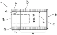
fig. 1A shows a schematic block diagram of a dental implant, illustrating the main aspects of the dental implant. The dental implant 1 comprises a crown portion 2 and a body portion 4 which are continuous with each other. The coronal portion 2 defines a proximal end 1p of the bone implant, while the body portion 4 defines a distal end 1d of the implant 1. The body portion 4 includes an inner core 4i that is adapted with at least one thread 6 that extends horizontally along the horizontal plane 30a and progresses along the length of the implant body core 4. The inner core 4 defines an inner diameter 4i of the body portion 4 and the thread 6 defines an outer diameter 4e of the body portion 4.
The shape and/or profile of the body portion 4 varies widely and may take on a variety of shapes and/or configurations and/or profiles, including for example, but not limited to, straight, tapered, conical, cylindrical, linear, parallel, symmetrical, asymmetrical, trapezoidal, hybrid conical, segmented, multi-segmented, and any combination thereof.
The implant 1 may further comprise micro-threads (micro-threads)8 along the coronal portion 2 and/or the body portion 4. Alternatively, the body portion 4 may include micro-threads 8 and threads 6.
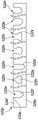
Fig. 1B shows a schematic block diagram of the dental implant thread 6, in particular showing aspects of the dental implant thread. Fig. 1B shows different profiles of the thread 6 with different characteristics as known in the art. The threads 6 extend from the implant core body portion 4 along a horizontal plane 30a indicated by dashed lines. The horizontal plane 30a includes two axes, a first axis along the medial-lateral axis 'M-L' and a second axis extending around the implant body 4 along the anterior-posterior axis 'a-P', as shown, for example, in fig. 8A.
The basic structure of the thread is an extension having an apical flank 32, a coronal flank 34 and a lateral edge 36 connecting the apical and coronal flanks, a base 30b connecting the thread 6 to the implant core 4, a thread depth 30d defined between the lateral edge 36 and the base 30 b.
The thread may also be defined by a number of additional parameters that provide and/or determine thread characteristics that delineate how well the thread behaves relative to the bone. Thread parameters may include, for example, but are not limited to: the profile of the thread interface 38, the overall shape of the core body portion 4i, how the threads progress along the length of the implant body, the number of thread starts, the number of grooves, the pitch of the threads, the dispersion of the threads along the implant body, etc., or any combination thereof.
Fig. 1B schematically illustrates thread parameters and some known configurations, wherein the thread may include straight sections or curved edges defined along the coronal flank 34 and/or apical flank 32 of the thread. The threads may be configured to be symmetrical or asymmetrical with respect to the horizontal plane 30 a. The angle of the thread along any portion thereof, including apical flank 32, coronal flank 34, lateral edges, and thread interface 38, can be controlled.
The following description makes simultaneous reference to fig. 2A through 5C, with like parts being identified with like reference numerals throughout the description.
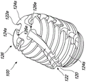
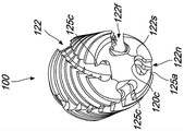
Fig. 2A shows an illustrative schematic view of a dental implant 100 according to an alternative embodiment of the present invention. Anchor 100 includes a proximal end 100p and a distal end 100d, distal end 100d also referred to as implant tip 126.
The implant 100 has a substantially cylindrical or conical or cylindrical form, including a crown portion 110 and a body portion 120. The body portion 120 includes threads 124 that fit into at least two or more grooves 122 disposed along the entire length of the implant 100.
The figures and accompanying description depict an implant having a crown portion 110, a body portion 120, threads 124, and at least two channels 122. However, the scope of the present invention is not limited to covering implants having all of these features in a single body and/or embodiment.
The present invention includes alternative embodiments of the implant, in which the implant may include at least one feature or any combination of features selected from the group consisting of: at least two flutes 122, a crown section 110, and a body core 120 c.
Fig. 2A illustrates a coronal portion 110, which is described and illustrated as a non-limiting example of an alternative coronal portion 110 that the implant 100 may have. The crown portion 110 is generally configured as an interface platform to facilitate coupling of the implant with other dental implant components, including, but not limited to, for example, abutments, crowns, bridges, dental prostheses, anatomical abutments, angled abutments, collars, ball attachments, healing caps, platform-switching abutments, and the like, or any combination thereof.
The crown portion 110 may be provided with an internal docking platform 50 (e.g., as shown in fig. 2E), or an external docking platform (not shown). Alternatively, the external docking platform may include, for example, but not limited to, an external hexagonal configuration as is known in the art. Optionally, docking platform 50 couples the implant to other dental implant structures (e.g., crowns, abutments, transferors, etc.). Optionally, the docking platform 50 may provide a machining interface to manipulate and/or machine the implant 100.
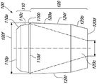
Fig. 2D illustrates the general shape of the various parts and segments that form the implant 100. As shown, the crown portion 110 and the body portion 120 comprise a substantially cylindrical variable diameter body. The implant 100 is characterized by a proximal end 120p of the body portion 120 configured to have an overall diameter greater than an overall diameter of the distal section 110b of the crown portion 110. Most preferably, this allows the physician to access a proximal portion of the body portion 120 from the crown portion 110, for example as will be described later in connection with the channel 122.
Optionally, the crown portion 110 may include threads 112 along at least a portion of the outer surface, fig. 2A. Optionally and preferably, threads 112, for example in the form of micro-threads, may be provided to improve bone retention and osseointegration. Alternatively, the coronal thread 112 may be configured with a double lead, a pitch of about 0.5mm, and a thread angle of about 25 degrees to about 35 degrees. Alternatively, the threads 112 may be configured according to the configuration of the body portion threads 124, and may be configured to promote intraosseous integration.
Alternatively, the thread 112 may be configured according to at least one or more thread parameters known in the art, including, for example, but not limited to, lead, pitch, thread angle, thickness, major diameter, minor diameter, taper angle, thread orientation, end position, start position, porosity, stop count, thread start count, thread run count, cut count, lead angle, etc., or any combination of the above thread variables and/or parameters.
Alternatively, the crown portion 110 may be unthreaded 112.
Preferably, the crown portion 110 comprises at least three or more substantially cylindrical and/or cylindrical segments that are continuous with one another. More preferably, the crown portion 110 includes three substantially cylindrical and/or cylindrical sections 110a-C, as shown, for example, in FIG. 2C. Optionally, each section comprises a trapezoidal cross-sectional profile having two parallel bases defining the proximal and distal diameters of each section respectively and two angled legs defining the outer surface of the respective section.
Alternatively, the cross-sectional profile of the crown sections 110a-c is optional, and may be selected to be circular, cylindrical, conical, trapezoidal, etc., or any combination thereof.
The first segment 110a defines a proximal segment of the coronal portion 110, including a proximal end 110p of the implant 100.
The second section 110b defines a distal section of the crown portion 110 and is continuous and fluid with a proximal portion of the body portion 120.
Optionally and preferably, the third segment 110c defines a middle segment of the crown portion 110. Most preferably, the intermediate section 110c is disposed between the proximal section 110a and the distal section 110 b. Alternatively, the crown portion 110 may be configured to include at least one or more intermediate sections 110 c.
Alternatively, the middle section 110c may be configured to have a cylindrical profile, wherein the proximal diameter of the middle section 110c and the distal diameter of the middle section 110c are substantially equal to each other.
Optionally and preferably, each of the crown segments 110a-c has a proximal diameter and a distal diameter defined around the base of the trapezoidal profile. Preferably, the diameters increase sequentially in the distal direction such that the proximal diameter of each of the sections is less than the distal diameter. Preferably, each crown segment 110a-c includes an angled outer surface corresponding to the angle defined by the legs of the trapezoidal profile.
Alternatively, at least one or more of the segments 110a-c of the coronal portion 110 may serve as an optional connection platform for the implant 100.
Alternatively, the proximal section 110a may serve as and provide at least two connection platforms, including an external connection platform 114 and a surface connection platform 116.
Alternatively and preferably, the distal section 110b can be configured to be continuous with the body portion 120 of the implant 100. Optionally and preferably, the distal diameter of the distal section 110b is equal to the proximal diameter of the body portion 120, while the proximal diameter of the distal section 110b is smaller than the proximal diameter of the body portion 110.
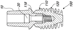
Alternatively, as shown in fig. 2E and 3B, the implant 100 can include a cavity disposed within the implant 100, the cavity being defined between the coronal portions 110 and at least partially within the proximal portion of the body portion 120. Preferably, the cavity 50 forms an opening at the proximal end 100p of the dental implant 100 and may be configured as a connection platform 118 for coupling and/or associating at least one or more dental implant components (e.g., including but not limited to abutments, crowns, bridges, abutment screws, set screws, dental prostheses, anatomical abutments, angled abutments, collars, ball attachments, healing caps, and the like, or any combination thereof).
Optionally, the cavity opening 50 (fig. 2E) may provide at least one or more attachment platforms 114, 116, 118 for attaching optional dental implant components, such as the abutment 10 and abutment screw 20, as shown in fig. 6A-6E.
Alternatively, the cavity 50 may form at least two connection platforms, including at least one interior connection platform 118 and at least one surface connection platform 114.
Optionally, the crown portion 110 may further include an external structure configured to attach a dental implant component such as an abutment, for example including, but not limited to, an abutment, a crown, a bridge, an abutment screw, a set screw, a dental prosthesis, an anatomical abutment, an angled abutment, a collar, a ball attachment, a healing cap, or the like, or any combination thereof.
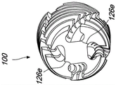
Alternatively, the coronal portion 110 can be configured to be coupled to and/or associated with and/or integrated with the abutment 10 using the abutment screw 20, as shown in fig. 6A-6E. Alternatively, the crown portion 110 may be configured to be coupled to and/or associated with an optional dental implant body component, including, for example and without limitation, an abutment, a crown, a bridge, an abutment screw, a set screw, a dental prosthesis, an anatomical abutment, an angled abutment, a collar, a ball attachment, a healing cap, or the like, or any combination thereof.
The coronal portion 110 extends distally (apically) toward a distal end (apical end) 100d, thereby defining a body portion 120 of the implant 100. The proximal end 120p of the body portion 120 is continuous with the distal end 110D of the distal section 110B defining the maximum overall diameter of the implant 100, as seen, for example, in fig. 2B, 2D.
Preferably, the overall diameter of the implant 100 is defined in two portions thereof (i.e., the body portion 120 and the crown portion 110). The overall diameter of the implant decreases apically along the length of the body portion 120 from the proximal end 120p to the top end 100 d. The overall diameter of the implant increases apically along the length of the coronal portion 110 from the proximal end 110p to the distal end 110 d. Thus, the implant 100 is substantially cylindrical and/or cylindrically shaped, having a barrel-like shape along its outer diameter, as seen, for example, in fig. 2B, 2D.
As best seen in fig. 2B, 2D, the body portion 120 may include at least two subsections, a proximal subsection 120a and a distal subsection 120B. Optionally and preferably, the body portion 120 more preferably includes a core 120c that may further include a plurality of subsections 121 that vary in size and configuration. Alternatively, each sub-section 120a, 120b, 121 may comprise a substantially cylindrical body having a trapezoidal profile, each sub-section decreasing in diameter distally such that the proximal diameter is greater than the distal diameter. Alternatively, the core segments 121 may have a cylindrical and/or trapezoidal profile.
The body portion 120 includes a core 120c that spans along the length of the body portion 120 from the proximal end 120p to the distal end 120 d. The core 120c includes a generally trapezoidal profile (fig. 2E), with the distal/tip 120d defining a minimum diameter at the tip 120d and a maximum diameter at the proximal end 120 p. Most preferably, the core 120c is substantially flat at the tips 120d, 126.
As shown in fig. 2B, 2D, optionally and preferably, the core 120c may be provided by a plurality of subsections 120a, 120B, 121, which may be configured to be cylindrical and/or trapezoidal.
For example, as shown in fig. 2B, the core 120c may be configured with a plurality of subsections, e.g., with the contour line 121a showing an optional core profile comprising six subsections, including a proximal subsection 120a, a distal subsection 120B, and four subsections 121 in between. It can be seen that the subsections 121 may be configured in any arrangement as cylindrical and/or trapezoidal and/or cylindrical, however the overall diameter of the core 120c decreases in order to the top side.
FIG. 2B shows an alternative configuration of the core 120c, shown as contour 121B, comprising four core sections, a proximal subsection 120a, a distal subsection 120B and two subsections 121 in between. It can be seen that the subsections 121 may be configured in any arrangement as cylindrical and/or trapezoidal and/or cylindrical, however the overall diameter of the core 120c decreases in order to the top side.
Most preferably, the core 120c defines an inner diameter of the body portion 120, while the flanks 124f of the threads 124 (extending outwardly from the core 120 c) define an outer diameter of the body portion 120.
As best shown in fig. 2A, 2E, and 3A-3D, the core 120c is adapted with threads 124 comprising at least one, and more preferably two or more threads extending along the length of the body portion 120 from the distal end l00D to the proximal end 120 p. The threads 124 include a base 124b that connects the threads 124 to the core 120 c. Thread bottom 124b includes a top side 124a, a coronal side 124c, and a lateral edge 124f (defining a thread width) connecting top side 124a and coronal side 124 c. The thread depth of the thread bottom 124b is defined between the lateral edge 124f and the core 120 c. The lateral edges 124f of the threads may be configured to have a variable width that increases in the coronal direction along the body section, configured such that the minimum width of the lateral edges 124f of the threads is adjacent the distal section 120b and the maximum width of the lateral edges of the threads is adjacent the coronal section 110.
Alternatively and preferably, the threads 124 may have variable thread depths that generally increase in the apical direction along the length of the body portion 120 such that a minimum depth of the threads is adjacent the coronal portion and a maximum depth of each thread is adjacent the apical end 120 d.
Alternatively, the threads 124 may have variable thread depths that generally increase in the apical direction along the length of the body proximal section 120a and generally decrease in the apical direction along the length of the body distal portion 120b such that a minimum depth of the threads is adjacent the coronal portion and a maximum depth of each thread may be located between the body distal portion 120b and the body proximal portion 120 a.
Most preferably, the threads 124 are provided in the form of a double thread having at least two starts. Alternatively, the threads 124 may be provided with a single head. Alternatively, the thread 124 may be provided with multiple heads.
Most preferably, as best shown in fig. 3C-3D and 4A-4C, the tips 100D, 126 have at least two leading cutting edges 126e that extend from the core 120C before the beginning of each thread 124, respectively, to act as lead-ins for the threads 124. Alternatively and preferably, the leading cutting edge 126e may be configured to have a coronal flank angle equal to the coronal angle of the thread 124 to facilitate initiation thereof. Optionally and preferably, leading edge 126e provides initial bone drilling element contact therein, thereby stabilizing implant 100.
Preferably, the threads 124 are provided with a thread angle of about 20 degrees to about 60 degrees. Optionally and preferably, the threads 124 are provided with a thread angle of about 20 degrees to about 40 degrees. Preferably, the threads 124 are provided with a thread angle of 35 degrees or 25 degrees.
Alternatively, threads 124 may be configured as a double-lead thread with a thread angle of 35 degrees and a pitch of about 2.1 mm.
Alternatively, threads 124 may be configured as a double-lead thread with a thread angle of 25 degrees and a pitch of about 1.1mm to about 1.8 mm.
Alternatively, threads 124 may be further configured according to at least one or more parameters known in the art, including, for example, but not limited to, lead, pitch, thread angle, thickness, major diameter, minor diameter, taper angle, thread orientation, end position, start position, porosity, stop count, thread start count, thread run count, cut count, lead angle, and the like, or any combination of the above thread variables and/or parameters.
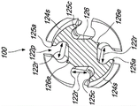
The implant 100 has at least two or more longitudinal channels 122 that form channels that span the entire length of the body portion 120 along the threads 124. Alternatively, the thread 124 may have at least two longitudinal recessed groove channels 122. Optionally and preferably, there may be four longitudinal recessed channels 122, for example as shown in the figures.
The grooves 122 are preferably configured to grind, collect, compress, and distract the contained bone when the dental implant 100 is rotated in both a clockwise or counterclockwise direction using a dental implant manipulation tool (e.g., a tool in the form of a dental handpiece).
Most preferably, the channel 122 has a proximal opening 122o accessible from the crown portion 110. Optionally, a proximal opening 122o (fig. 3A-3D) to the channel 122 allows access to the channel 122 from the coronal portion 110 to allow a physician to introduce bone, bone graft material, osteogenic media, bone graft media, bone growth drugs and/or promoters into the channel 122 to promote the bone growth process and improve osseointegration of the implant 100 around any portion of the implantation site (e.g., the mandible or maxilla). Optionally, the proximal opening 122o may also provide a window for removing any excess bone compacted within the trough 122. Optionally and preferably, the proximal opening 122o further provides for the accommodation and/or introduction of bone into the occlusal surface, most preferably for providing support to the gums.
Optionally and preferably, the groove 122 forms a channel along the length of the body portion 120, the channel having a longitudinal axis selected from the group consisting of: linear, curved, arcuate, S-shaped, spiral, etc., or any combination thereof. Figures 3C-3D and 4B show examples of curved longitudinal axes of the grooves 122 that curve along the length of the body portion 120.
Alternatively, the longitudinal axis of the channel 122 may be defined according to the profile of the core portion 120c (e.g., according to lines 121a, 121 b).
Optionally, the implant 100 includes a plurality of grooves 122, and each groove and/or group of grooves 122 may be adapted with a separate longitudinal axis. For example, an implant comprising four grooves may be configured such that each pair of opposing grooves may have a different longitudinal axis. For example, an implant comprising three grooves may be configured such that each groove may have a different longitudinal axis.
Alternatively and preferably, the implant comprising a plurality of grooves may be configured such that the grooves are equally distributed along the circumference of the body portion 120, thereby dividing the thread 124 into equally spaced thread sub-sections. For example, as shown, the implant 100 including four equally spaced grooves divides the thread 124 into four wing members.
Alternatively, an implant comprising a plurality of grooves may be configured such that the grooves are unequally distributed along the circumference of the body portion 120, thereby dividing the thread 124 into a plurality of unequally spaced, unequally sized thread sub-sections.
Preferably, each groove 122 divides the thread 124 into a number of smaller thread sub-sections equal to the number of grooves 122. As shown, implant 100 is provided with four grooves 122 forming four wing-like threaded sub-sections 124 s.
Most preferably, the groove 122 is configured to have a bottleneck profile across the bottom and depth of the thread 124. Wherein a groove 122 is formed between the core 120c and the threaded lateral edge 124 f. Preferably, the bottleneck profile is in the shape of an oval flask, for example as shown in figures 5B to 5C.
Preferably, the bottleneck profile 122p may be formed by two S-shaped curved shoulders 122S and a neck portion 122n, the shoulders 122S extending forwardly from the core 120c towards the thread lateral edges 124f, with an oval recess 122r formed along the bottom and the neck portion 122n formed across the side surface 124 f. Most preferably, the major axis of the oval-shaped recess 122r is defined along the core 120c, while the minor axis is formed across the bottom of the thread 124 between the core 120c and the side 124 f.
Most preferably, the bottleneck-shaped recessed channel 122 formed along the threads 124 forms a plurality of thread sub-sections 124s, as best shown in FIG. 4C, wherein each sub-section 124s forms a winged thread having two hypotenuses 122e along a thread flank 124f defined by the neck portion 122n of the channel 122. Most preferably, this significantly increases the number of cutting edges provided along the implant 100.
Most preferably, the grooves 122 form a plurality of subsections 124s and/or blades and/or wings along the thread 124, as shown in fig. 4C, significantly increasing the surface area of the implant 100, wherein osseointegration is promoted and 360 degree support of the implant is ensured.
Optionally and preferably, because the apical surface 126 is flat and/or apical relative to the threads 124s, the apical surface 126 facilitates sinus lifting while retaining the nasal mucosa, and thus the surface 126 may serve as a barrier to protect the nasal mucosa from the threads 124 s. Thus, the implant 100 may facilitate sinus lift procedures because by rotating the implant in a clockwise and/or counter-clockwise direction, bone may be guided directly at the apical side, allowing bone to grow, while the distal surface 126 further helps maintain the integrity of the nasal mucosa.
Most preferably, the grooves 122 are configured such that the length of the shoulder 122s tapers in a proximal direction along the length of the implant 100 such that the shoulder 122s is longest at the proximal end l00d and shortest adjacent to the coronal section 110.
Optionally, shoulder 122S is S-shaped, configured with an inner radius 122i of about 0.4mm and an outer radius 122q of about 0.3 mm; with the inner radius 122i defining an oval-shaped recess 122r and the outer radius defining a neck 122n, as best shown in fig. 5B-5C.
Alternatively, the distance at the widest portion of the oval depression 122r is about 1.6mm, while the distance at the widest portion of the neck 122n is about 1.0mm, as best shown in FIG. 5B.
Alternatively, the grooves 122 may be configured to have a pitch of 35mm along the length of the implant 100. Alternatively, the groove 122 may be configured to have four threads. Alternatively, the grooves 122 may be configured to have the same number of threads as the grooves 122. Alternatively, the groove 122 may be configured according to and/or in accordance with at least one or more parameters that define the threads 124.
Alternatively, the groove 122 may be configured to have a thread profile based on at least one or more thread parameters, including, for example, but not limited to, lead, pitch, thread angle, thickness, major diameter, minor diameter, taper angle, thread orientation, end position, start position, porosity, stop count, thread start count, thread run count, cut count, lead-in angle, and the like, or any combination of the above thread variables and/or parameters.
Most preferably, the threads 124 and grooves 122 are configured to provide a cutting surface and collect bone when the implant 100 is rotated in either a clockwise or counterclockwise direction.
Fig. 5C illustrates an alternative configuration and profile of the trench 122 in accordance with the present invention. Fig. 5C illustrates an alternative configuration for the groove 122, wherein the profile 122p may be configured according to the dimensions of the neck 122n and the oval recess 122r, for example as shown.
Fig. 2B and 2D illustrate alternative profiles for the body portion 120 and show alternative configurations for the inner core 120 c. As shown by lines 121a, 121b, the core 120c may be configured from a plurality of subsections 120a, 120b, 121 in a selectable combination of cylindrical and/or trapezoidal and/or cylindrical subsections.
FIG. 2C illustrates an alternative embodiment of the present invention, in which the crown segment 110 has three subsections 110a-C, as described above. Alternatively, the crown section 110 may fit over any alternative implant body and is therefore not limited to the implant body 120 described herein.
Fig. 2E shows a cross-section of the implant 100 showing the configuration of the threads 124 and the configuration of the core 120 c.
Fig. 3A-3D show perspective views of an alternative internal interface cavity 50 that facilitates attachment to alternative dental implant body components, as previously described, including, for example, but not limited to, an abutment, a crown, a bridge, an abutment screw, a set screw, a dental prosthesis, an anatomical abutment, an angled abutment, a collar, a ball attachment, a healing cap, and the like, or any combination thereof.
The perspective view of fig. 3B further illustrates the crown entering the trough 122 via the opening 122 o.
Fig. 3C-3D and 4A-4C illustrate top perspective views of the tip 126 including the leading cutting edge 126e and the start of the dual lead thread 124, as described above.
Fig. 4C shows the formation of a number of thread sub-sections 124s and/or wings and/or blades equal to the number of grooves 122.
The tip 126 is substantially flat and includes at least one leading cutting edge tip 126e extending from the core 120c before each thread 124 begins. Optionally and preferably, the leading cutting edge tip 126e preferably stabilizes the implant within the bone and allows bone to grow around the implant 100. Thus, the tip 126e may be used with the implant 100 within a 1mm bone and introduce bone grafting and/or generation media around the surface of the implant.
Preferably, the tip 126, 100d further comprises a first threaded subsection 124s (wing, blade) having two opposing laterally inclined ends 122e along the side surface, including a first (apical) wing end 125a and a second (coronal) wing end 125 c. Optionally and preferably, the second (coronal) wingtip portion 125c may further comprise an undercut of the apical face 124a, wherein the second (coronal) wingtip portion 125c is elevated relative to said first (apical) wingtip portion 125a to facilitate drilling.
Fig. 4C further shows the profile of the groove 122 as a bottleneck configuration 122p formed by two shoulders 122s forming a neck portion 122n and a recess 122r for collecting and accommodating bone as the drill is rotated in either a clockwise or counterclockwise direction. Optionally and preferably, the shape and/or profile 122p of the trench recess 122r may be determined by controlling the dimensional ratio of the neck portion 122n to the recess 122 r.
Figure 5A illustrates an alternative configuration of thread 124 showing thread pitch 124p, thread lead 124L shown as a double lead, and thread angle 124 o. Figure 5A depicts an alternative thread configuration in which the number of thread leads 124L is two, the thread angle 124o is equal to about 35 degrees, and the thread pitch 124p is about 2.1 mm. Further, alternative thread parameters may be, for example, two thread leads 124L, a thread angle 124o equal to about 25 degrees, and a thread pitch 124p of about 1.8 mm.
Fig. 5B illustrates an alternative configuration for the groove 122, showing a groove neck profile 122p formed between two shoulders 122s having an inner radius 122i and an outer radius 122q to form a recess 122r and a neck 122 n.
Fig. 5C illustrates an alternative configuration and profile of a groove 122 according to the present invention having an oval-shaped bottom portion 122r and a neck portion 122n that may be configured relative to one another and form an edge 122 e. The neck 122n preferably defines a groove edge 122e on either side of the neck 122 n. Alternatively, the trough edge 122e may be configured symmetrically or asymmetrically about the neck 122n, with differently configured trough edges 122e formed on either side of the neck 122n, as shown, for example, in fig. 5C.
Alternatively, the grooves 122 may exhibit a different profile along their length, as shown, for example, in FIG. 5C. Alternatively, each of the grooves 122 of the implant 100 may exhibit a different groove profile along its length.
Fig. 6A-6F illustrate alternative abutments 10 associated with an implant 100 using abutment screws 20, each utilizing a different attachment platform on which the implant 100 is disposed. Figure 6A illustrates an implant 100 utilizing an external connecting platform 114 to support an alternative abutment 10 along a coronal section 110 c.
Figure 6B illustrates a further alternative abutment 10 supported on the implant 100 by the external connection platform 114 without the surface connection platform 116.
Figures 6C-6D illustrate the use of an internal connection platform 118 formed with an interface cavity 50, with the abutment 10 emerging from the interface cavity 50, which does not interface with the outer surface of the crown section 110.
Figure 6E shows the abutment 10 and locking screw 20 using the surface attachment platform 116.
Fig. 6F illustrates an alternative embodiment of a one-piece dental implant 130, wherein the implant 100 according to the alternative embodiment is integrally formed and conformed to the abutment 10.
Fig. 6G illustrates an alternative embodiment of a two-piece dental abutment 10c, such as similar to the abutments illustrated in fig. 7F and 11A, configured to be associated with the crown portion 110 along threads 112 disposed along an outer surface of the crown portion. Optionally, the abutment 10c can be further configured to be disposed along and sealed to at least one of the crown sections 110a-c, and more preferably along the distal section 110 b. Alternatively, such an abutment 10c may be used as an abutment replacement after bone resorption, as described in more detail in figure 11A.
Referring now to figures 7A-7F, an alternative embodiment of an abutment 10 is shown in accordance with an alternative embodiment of the present invention, the abutment 10 being configured to be associated with and/or otherwise coupled to the implant 100 along the coronal portion 110 and/or any portion 110a-c, 112, 114, 116, 118 thereof.
Figures 7A-7B show perspective views of an alternative abutment 10 according to an alternative embodiment of the present invention.
Figures 7C-7E are cross-sectional views of the abutment depicted in figures 7A-7B showing alternative configurations of the abutment 10, showing alternative connection platforms for association and/or coupling with the implant 100.
The abutment 10 according to the present invention provides coupling with the implant 100, thereby facilitating placement of the implant and abutment in alternative configurations and exposed profiles, including, for example, but not limited to, bone level, tissue level, intraosseous, and the like.
Most preferably, the abutment 10, in combination with the implant 100, provides a suitable implant location and exposure profile based on the implant site and the mesial-distal plane, and/or the cheek-palate plane, and/or the cheek-tongue plane.
Preferably, the abutment 10 comprises a middle portion 16 that interfaces with the connecting profiles 116, 114, 118 of the implant 100 to facilitate proper formation of an exposed profile at the implant site relative to at least one plane selected from the group consisting of a mesio-distal plane and/or a cheek-palate plane and/or a cheek-tongue plane, or any combination thereof.
The abutment 10 has proximal and distal ends 12, 14 and an intermediate portion 16 disposed therebetween. The abutment 10 includes a substantially cylindrical core spanning the proximal end 12 and the distal end 14, shown in phantom at 10C (fig. 7D, 7C), and defining a central axis 10a (fig. 7C-7D) of the abutment 10 and an outer surface shaped along the length of the abutment 10 between the distal end 14 and the proximal end 12 to define the shape and configuration of the abutment 10. Alternatively and preferably, the surfaces of each portion of the abutment 10 (i.e., the proximal end 12, the intermediate portion 16, and the distal end 14) can be formed to provide alternative forms and functions, as is known in the art. Most preferably, an alternative embodiment of the present invention provides an abutment 10 wherein the intermediate portion 16 is configured to couple and/or interface and/or otherwise associate with at least one connecting profile 116, 114, 118 of the implant 100, as described above.
Alternatively, the intermediate portion 16 may provide a platform transition, such as shown, wherein a wider sole is provided along the proximal portion 12 to facilitate a wide coupling sole to facilitate coupling of a crown (not shown) on the proximal portion 12.
Most preferably, the proximal portion 12 may be provided in an alternative form to couple to a restorative structure or prosthetic component such as an over-denture abutment, bridge, denture, crown, or the like. Alternatively, the proximal portion 12 may be provided in an alternative attachment platform and form known in the art, including, for example, but not limited to, a ball attachment, an over-the-denture attachment, a casting, a UCLA, a threaded, gold, a snap, an angled, a straight, an angled, an internal cap attachment, and the like, or any combination thereof.
The abutment 10 further includes a prosthetic coupling portion 14c disposed along the distal end 14. Preferably, the coupling portion 14c is configured to couple with the implant 100, and is most preferably provided in an alternative configuration to facilitate anti-rotational coupling with the coronal portion 110. Optionally and preferably, the coupling portion 14c includes a coupling platform to mirror and couple with at least a portion of the implant 100, preferably along the coronal portion 110, such that they optionally and preferably fit in a one-to-one and/or a male-female relationship with respect to any portion or surface of the coronal portion 110 (e.g., including but not limited to 110a, 110b, 110c, 112, 114, 116, 118, etc.). For example, an external coupling platform provided around the coronal portion 110 that provides a male coupling member can be coupled with a corresponding internal coupling platform 14c (including a female coupling member therein) provided on the abutment distal end 14. For example, an internal coupling platform provided around the crown portion 110 that provides a female coupling member may be coupled with a corresponding external coupling platform 14c (including a male coupling member therein) provided on the abutment distal end 14.
Coupling portion 14c is shown in a non-limiting alternative outer hexagonal configuration, however it may be implemented in a variety of alternative configurations. Alternatively, the coupling portion 14c may be provided as an internal configuration, an external configuration, or a combination thereof, which may be depicted, for example, according to the type of connection platform provided on the coronal portion 110 of the implant 100, as is known in the art. Alternatively, the abutment 10 may be provided in a rotational form, for example including but not limited to at least one or more or any combination thereof selected from the group consisting of: such as an inner six-receptor socket, scalloped, inner dodecagon, outer dodecagon, inner hexagon, outer octagon, inner octagon, outer spline, inner spline, morse taper, inner morse taper, unibody, inner six lobes, outer six lobes, inner three lobes, outer three lobes, inner six splines, outer six splines, internal threads, internal pentagon, external threads, internal square, external square, internal five lobes, internal four lobes, internal three splines, external triangle, internal eight splines, external six lobes, internal eight lobes, internal tube and tube insert, triangle, polygon comprising n sides (where n > 3 or more), and the like, as known in the art.
The abutment 10 includes a central bore 18 extending through at least a portion thereof from the proximal end 12 to the distal end 14. Optionally and preferably, a central bore 18 is provided for receiving a set screw and/or an abutment screw 20. Optionally and preferably, an abutment screw 20 is provided for coupling the abutment 10 to the implant 100, as previously described and as shown in fig. 6A-6D.
The abutment 10 includes an intermediate portion 16 defined between the proximal end 12 and the distal end 14. Preferably, the intermediate portion 16 defines an exposed profile of the abutment as it emerges from the implant 100 toward the crown of the implant (not shown). Most preferably, the intermediate portion 16 serves to define a connection platform of the abutment for coupling or otherwise associating with one of the three connection platforms 114, 116, 118 defined along the implant 100, as described above.
As shown, for example, in fig. 7C, the intermediate portion 16 includes a submount surface 16a (as described above) for coupling and/or interfacing with the internal connection platform 118. Optionally and preferably, abutment surface 16a is a sloped surface that gradually slopes from distal end 14 toward proximal end 12, and most preferably, surface 16a may be configured to have an angle of about 3 degrees and up to about 50 degrees, more preferably about 4 degrees to about 45 degrees. Most preferably, the angle of the surface 16a may be defined and/or configured according to the attachment platform 118 of the implant 100.
As shown, for example, in fig. 7D, the intermediate portion 16 includes abutment surfaces 16c and 16D (described above) for coupling and/or interfacing with the external connection platform 114. Optionally and preferably, the abutment surface 16c is a sloped surface having an angle of up to about 70 degrees. Most preferably, the angle of the surface 16b may be defined and/or configured according to the attachment platform 114 of the implant 100. As shown, the surface 16c extends from the core formed by the proximal portion 14 at the boundary that meets the intermediate portion 16. Preferably, the surface 16c includes an extension 16d extending from the core proximal portion 14. The surface 16d is a substantially flat surface disposed substantially perpendicularly (at an angle of about 90 degrees) with respect to the central axis of the submount 10 and/or submount core. Surface 16c extends from surface 16d to form a downwardly inclined angle extending distally from surface 16d to form surface 16c, characterized in that surface 16c has an angle of up to about 70 degrees with respect to surface 16 d.
Alternatively, the length and/or size of the surfaces 16a, 16b, 16c, and 16d may be configured and adjusted relative to the size and size of the implant 100 and/or at least one of the connection platforms 112, 114, 116, 118 and/or the segment surfaces 110a, 110b, 110 c.
As shown, for example, in fig. 7E, the intermediate portion 16 includes a submount surface 16b (as described above) for coupling and/or interfacing with the surface attachment platform 116. Optionally and preferably, the abutment surface 16b is a substantially flat, non-sloping surface that is substantially perpendicular (approximately 90 degrees) relative to the central axis of the abutment 10, wherein the surface 16b extends from the abutment core defined by the distal portion 14 at the boundary defined between the intermediate portions 16. Most preferably, the profile and/or angle of the surface 16b can be defined and/or configured according to the surface attachment platform 116 of the implant 100.
Figure 7F illustrates a cross-sectional view of an alternative abutment 10c configured to be associated with the outer surface of the crown portion 110, wherein the crown portion is adapted with threads 112 and, to this end, the abutment 10c includes corresponding threads 15t for coupling therewith. Preferably, the abutment thread 15t is disposed along the inner surface of the crown portion cavity 15c, as shown, for example. Optionally and preferably, the cavity 15c is configured to receive and couple with a coronal portion 110 of the implant 100, the coronal portion 110 of the implant 100 having threads 112 disposed along at least a portion of an outer surface thereof. Optionally, the abutment 10c may further comprise a central bore 18, as described above.
Embodiments of the present invention provide novel thread configurations for dental implants, such as shown in fig. 8A-8H. The threads and/or threading are configured to have at least one or more profile modifications 140 relative to the horizontal axis 30a of the implant threads. The profile modification can be disposed on at least one of the apical 32 or coronal 34 sides of the thread relative to a horizontal axis of the thread. Due to the angle defined along the horizontal axis 30a, a trim 140 may be provided.
Fig. 8B to 8H show illustrative schematic views of an exemplary dental implant thread 6 according to an alternative embodiment of the present invention. Fig. 8B shows an alternative thread profile along the horizontal plane 30 a.
As described above in connection with fig. 1B, the thread 6 includes a apical flank 32, a coronal flank 34, and a lateral edge 36 connecting the apical and coronal flanks, a base 30B connecting the thread to the core, defining a thread depth 30d therebetween. The thread depth 30d is defined along the medial-lateral axis (M-L) of the horizontal plane 30a of the thread; adjacent threads defined between adjacent thread bottoms 30b are connected over the outer surface of the implant core 4 defining the thread interface 38.
The thread crest 32 or the thread crest 34 can be adapted with at least one profile modification 140 along at least one axis of the horizontal plane 30a (including the medial-lateral axis M-L, and/or the anterior-posterior axis a-P as shown in fig. 8A). Preferably, the contouring along at least one axis of the horizontal plane will define at least two subsections 142, 144 along the horizontal plane 30a, for example as shown in fig. 8B-8H.
The profile modification can be accomplished along the M-L axis, as shown in FIG. 8A, for example, as shown by thread profile 140M, or along the A-P axis, as shown by thread profile 140 a.
Alternatively, the threads may include at least one or more horizontal profile modifications 140. Alternatively, there may be up to about five profile modifications 140 along a horizontal axis on the apical side 32 or coronal side 34 and along at least one axis of the horizontal plane.
Alternatively, each of the contouring modifications 140 may exhibit a variable angle of up to about 180 degrees along each of the apical side 32 or coronal side 34.
Alternatively, the embellishment 140 may form a substantially symmetrical thread surface along the thread, as shown, for example, in fig. 8B and 8G. Alternatively, the threaded surface may be configured to be substantially asymmetric, for example as shown in fig. 8C-8F.
Alternatively, a level modification 140 may be applied along at least one of the apical side 32 or coronal side 34, and the level modification may be curved (fig. 8E-F) and/or linear (fig. 8B-C), or it may comprise a combination of itself, for example as shown in fig. 8G.
Optionally, each additional contour modification 140 introduced along at least one axis of the horizontal plane increases the number of individual subsections defined by at least one subsection 142, 144 along the horizontal plane.
Alternatively, at least one of the threaded apical flank 32 or the threaded coronal flank 34 may be adapted with at least one and up to five profile modifications 140 along a medial-lateral axis or along an anterior-posterior axis 140a forming the modifications 140m, respectively.
Alternatively, the implant 100 may be configured to include at least two threads 124, each of which may be respectively configured to include at least one or more level surface modifications 140.
Alternatively, each of the plurality of threads 124 may be collectively and/or individually/independently configured along its horizontal plane 30a to include at least one horizontal plane thread modification 140 on the M-L axis or the a-P axis and along at least one of the thread crest 32, the thread coronal flank 34, and/or the thread lateral edge 36.
Alternatively, the shape modification 140 may define an angle of up to about 180 degrees with respect to the horizontal plane 30 a.
Alternatively, the threads may be configured to be symmetrical about at least one axis of the horizontal plane 30 a.
Alternatively, the threads may be configured to be asymmetric about at least one axis of the horizontal plane 30 a.
Alternatively, at least one of the threaded apical flank 32 or the threaded coronal flank 34 or the lateral edge 36 may have at least one concave recess 150, as shown, for example, in FIG. 8G. Alternatively, the threads 124 may be fitted with a plurality of recessed grooves 150, as shown, for example, in FIG. 8G.
Alternatively, the recessed groove 150 may be any shape.
Optionally, at least one dimension of the recessed groove (150) is configured from about 0.01mm to about 0.7 mm.
Alternatively, the depth of the threads 124 may be configured from about 0.1mm to about 2 mm. Alternatively, thread interface 38 may be configured to assume any shape or angle.
Alternatively, thread interface 38 may include, for example, but is not limited to: contoured, curved, angled, linear, etc., or any combination thereof.
Alternatively, the thread interface 38 may be substantially linear, having an angle of up to about 60 degrees.
Alternatively, the thread interface 38 may comprise a length of up to about 2 mm.
Optionally, at least one surface selected from the group consisting of the threaded apical flank 32, the threaded coronal flank 34, the lateral edge 36, and the thread interface 38 further comprises at least one outwardly extending extension 152, as shown, for example, in fig. 8G. Alternatively, the thread may include a plurality of outwardly extending extensions (152).
As shown in fig. 8A, the profile modification can be accomplished along at least one axis of the horizontal plane, such as at least one of on the M-L axis (as shown by thread profile 140M), or along the a-P axis (as shown by thread profile 140 a).
Fig. 8I illustrates horizontal surface profile modifications 140a, 140m applied to the threads 124 to form sharp edges 122e, for example, as shown, for cutting, compacting and guiding bone into the channels 122. The edge 122e is formed with two profile modifications 140a, 140M along the M-L axis and the A-P axis, respectively, of the horizontal plane, for example as shown. The first contoured trim 140a is configured along the horizontal plane 124f and the second contoured trim 140m is configured along the coronal surface 124 c.
Fig. 8J illustrates a thread 124, which is similar to the thread illustrated in fig. 8I, wherein the thread coronal surface 124c is adjusted to introduce an undercut 140c into the horizontal plane profile modification imposed on the M-L axis.
Fig. 8K shows an alternative thread 124 wherein the horizontal plane profile adjustment is made along the thread edge 124f along the a-P axis, with the introduction of an undercut 140c along the thread face 124, for example as shown.
Fig. 8L-8P illustrate alternative horizontal surface thread modifications as described above.
Fig. 8L shows an alternative thread 124 having a grooved edge 122 e.
Fig. 8M shows a similar thread 124, wherein however edge 122e (shown in fig. 8L) further includes a horizontal modification 140M to form a more pronounced angle at edge 122e, wherein edge 122e forms an acute angle with respect to groove recess 122 r.
Fig. 8N shows a similar thread 124, wherein however edge 122e (as shown in fig. 8L-8M) further includes a second horizontal modification in the form of modification 140a along edge 124f along the a-P axis. Alternatively, the threads 124 may include a plurality of such profile modifications.
FIG. 8O shows a similar thread 124, wherein however edge 122e (shown in FIG. 8M) further includes a horizontal modification in the form of a curved undercut 140c along the M-L axis that creates curved edge 122 e. Alternatively, such curvature 140c may be used to enhance osseointegration.
Fig. 8P shows a thread 124 with other horizontal surface modifications, where edge 124f is provided with a double curved surface, where a multi-point edge 122e is formed.
Fig. 9A shows an illustrative schematic view of an alternative dental implant 100 according to the present invention. Implant 100 includes threads 130 configured to have a horizontal profile according to the present invention, as described above in fig. 8A-8H. Fig. 9A further depicts an implant whose coronal section 110 has functional threads 114 for interfacing with cortical bone. Fig. 9A further illustrates a crown segment 110 that includes depressions and/or grooves 115 along the surface of the thread 114.
Alternatively, in case the coronal section has to be removed due to bone resorption, the coronal section 110b of the implant 100 may be further customized to facilitate removal of the coronal section.
Figure 9B shows a schematic representation of a cross-sectional depiction of a crown portion 110 according to the present invention, particularly illustrating two connection interfaces and/or platforms 50, 52 configured to receive the abutment 20 and optional set screws as needed.
Fig. 9C shows an alternative embodiment of the dental implant of the present invention, the coronal portion of which is fitted with at least one or more concave grooves 115 along the surface of the coronal portion. Alternatively, this may be applicable to any implant having a coronal section.
Alternatively and preferably, the implant coronal section with cortical cutting threads 124 as described above in connection with fig. 2A-4C may be fitted with a recessed groove 115.
Alternatively, the crown portion 110 may be fitted with a plurality of concave grooves 115. Alternatively, the concave recess 115 may fit along the crown thread 112.
Alternatively, the concave groove 115 may have any shape.
Optionally, the concave groove 115 is configured to have at least one dimension of about 0.01 to 0.5 mm.
Alternatively, the shape of the recessed groove may be selected from the group consisting of: oval, ovoid, elliptical, circular, quadrilateral, trapezoidal, polygonal with n sides, where n is at least three (n >2), any combination thereof, and the like.
Optionally, the crown portion (110) may have at least one outwardly extending extension (115 e). Optionally, the crown portion 110 may further include a plurality of outwardly extending extensions (115 e).
Fig. 10A to 10C show illustrative schematic views of an alternative embodiment of a dental tool according to an alternative embodiment of the invention. The tool is used to assist in the removal of the coronal section of an implanted dental implant.
Fig. 10A shows an alternative embodiment of a coronal portion removal tool 200, the special tool 200 being used for filing and/or removing a coronal section 110 of a dental implant 100, the device having: a dental machining connection interface 202 for coupling with a dental handpiece tool; a disc-shaped working surface 204 having at least one surface or edge that can be coated with a medium for cutting and/or filing at least a portion of the dental implant 100; an implant interface portion 210 for insertion into a bore of a dental implant, the interface portion 210 comprising: a central body portion 212 for fitting within the central bore recess of the implant; an annular portion 214 for allowing the tool to freely rotate while associated with the implant bore; and a distal cap 216 for securely associating a tool with at least a portion of the bore portion and for sealing the implant bore.
Optionally, the central body portion of the device 200 may be configured to be flexible or adjustable in the vertical direction. Optionally, the central body portion may be fitted with a spring 212s to facilitate height adjustment.
Alternatively, the central body portion may be configured to be telescopic.
Alternatively, the central body portion may have an adjustable diameter.
Optionally, the central body portion comprises a core on which a plurality of adapters are fitted such that the central body portion is freely rotatable within the central bore of the dental implant.
Optionally, the ring portion 214 comprises ball bearings.
Optionally, the annular portion may include friction reducing elements to facilitate rotation.
Alternatively, distal cap 216 may be provided by a material and/or coating selected from the group consisting of silicone, polytetrafluoroethylene, and the like.
Fig. 10B to 10C show an alternative embodiment of a dental tool 220, 230 for filing and/or facilitating removal of the coronal section 110 of an implanted dental implant 100, the device having: a dental machining connection interface 202 for coupling with a dental handpiece tool; a cylindrical tool body 224, 234 functionally coupled to the dental tool interface 202 and configured to rotate when activated with a dental handpiece tool; a cylindrical machining body 234, 224 having at least one machining surface or edge 236, 226a, 226b that can be coated with a medium for cutting and/or filing at least a portion of the crown portion 110 of the dental implant 100; and a stop interface portion 238 for limiting advancement of the cylindrical body 224, 234 along the coronal section of the implant.
The tool depicted in fig. 10B differs from the tool shown in fig. 10C in the stopping interface used. The tool in fig. 10C utilizes a drill plug 228, while the tool in fig. 10B utilizes an implant body skirt plug 238.
Alternatively and more preferably, the cylindrical tooling bodies 234, 224 can include an open lower surface configured to receive the coronal portion 110 of the implant 100.
Alternatively, the tooling surfaces or edges 236, 226a, 226b may be disposed along the inner surface of the cylindrical tooling bodies 234, 224.
Alternatively, the working surface may be adapted with an abrasive medium for abrading and/or cutting the implant around the coronal portion. Alternatively, the media may, for example, include, but are not limited to, media selected from diamond sand, diamond-like carbon, and the like, or any combination thereof.
Optionally, the stop interface portion 238 may be configured to be associated with at least a portion of the coronal segment 110 or the implant body 122, 110B, e.g., as depicted in fig. 10B.
Alternatively, the stop interface portion 238 may be provided in the form of a skirt that may be configured to fit over an upper portion of the implant body 120, wherein the skirt may distally fit over the cylindrical tooling portions 234, 224.
Alternatively, the stop interface portion 228 may be provided in the form of an implant bore adapter for associating over an implant bore provided along the implant coronal section 110, such as shown in fig. 10C.
Fig. 11 to 12 show illustrative schematics depicting an alternative method according to an embodiment of the invention when the dental implant is bone-resorbed after years of implantation, wherein some parts of the implant are exposed over time due to bone loss around the implant, in particular in the coronal section of the implant.
Fig. 11A illustrates an alternative method of treating such bone resorption by exposing and cleaning the coronal portion of the implant to bone level, and then coupling the exposed coronal section with a new abutment 22 configured to be associated therewith.
Alternatively, crown portion 110 may be reconfigured and re-screwed using an optional special tool, such as the tool depicted in fig. 10B-10C.
Fig. 11B shows an alternative method of treating bone resorption due to a dental implant. Fig. 11B schematically shows exposure of the coronal section over time, after which the coronal section 110 is exposed and ready to be removed while the implant remains implanted in the bone. Alternatively, the crown portion 110 may be removed using any of the alternative tools depicted in fig. 10A-10C.
Similarly, fig. 12A-12B schematically illustrate bone resorption at the implant site over time. The coronal portion of the implant is first exposed and/or cleaned as desired, after which the coronal portion is removed using a special tool 220, 230, 200. Fig. 12B shows an additional abutment configuration 20 that may be coupled to an implant without a conical portion, e.g., as shown.
Referring now to fig. 13A to 16, an alternative embodiment of the dental implant internal connection platform shown in fig. 13A to 14B, the corresponding abutment shown in fig. 14A to 15G, and the dedicated implant introduction tool shown in fig. 16 of the present invention will be discussed.
Fig. 13A to 16 show a dental implant, an implant abutment and a special tool all interrelated by an internal conical interface platform, which may be provided on the dental implant, thus requiring a corresponding interface on any dental tool and/or structure associated and/or interfacing with the implant.
Fig. 13A-13B illustrate an alternative embodiment of an implant 1300 having an internal conical connecting platform 1302 of the present invention. Most preferably, the dental implant 1300 has an internal conical connecting platform 1302 along the bore configured to receive universal implant abutments 1320, 1330. The internal connecting platform 1302 is an internal bore that extends distally from the proximal end of the implant 1300 at the coronal portion into the medial portion of the implant body. The internal connection platform 1302 is preferably centered along the implant body.
The implant connection platform 1302 preferably includes a distal portion 1304, an intermediate portion 1310, and a proximal portion 1305 that are fluidly and continuously connected to one another.
Optionally and preferably, the attachment platform 1302 is characterized by a proximal portion 1305 that includes a generally conical profile, wherein the attachment platform 1302 is enabled to serve as an abutment and/or receiving platform for a universal abutment 1320 (fig. 14A-15G) for implants having a variety of sizes and/or diameters.
Most preferably, the attachment platform 1302 includes at least two anti-rotation interfaces, a first anti-rotation interface 1311 disposed along the intermediate portion 1310 and a second anti-rotation interface 1314 disposed along a proximal portion adjacent the proximal end 1302p of the implant.
Preferably, distal portion 1304 is a substantially cylindrical bore having threads for coupling with a set screw, as is known in the art. Preferably, the intermediate portion 1310 defines an anti-rotation interface 1311 in the form of an anti-rotation machining interface for manipulating an implant with a tool, such as in the form of an internal hexagon as shown in figures 13A-13B.
Alternatively, the mid-portion anti-rotation connection interface 1311 may be any anti-rotation machining interface known in the art, including, but not limited to, at least one or more or any combination thereof selected from the group consisting of: such as an internal six-receptor socket, scalloped, internal dodecagon, internal hexagon, internal octagon, external spline, internal spline, morse taper, internal six lobes, internal three lobes, internal six splines, internal thread, internal pentagon, internal square, internal five lobes, internal four lobes, internal three splines, internal eight lobes, internal tube and tube insert, triangle, polygon comprising n sides (where n > is 3 or more), and the like as known in the art.
Most preferably, the proximal portion 1305 is provided in the form of a substantially conical bore having a smaller diameter at its distal end 1305d adjacent the intermediate portion 1304 and a larger diameter at its proximal end 1305p defined at the proximal end 1302p of the implant.
Optionally and preferably, the conical bore 1305 defines a wall that is uniformly angled and/or sloped along the length of the proximal portion 1305 from the distal end 1305d to the proximal end 1305p, for example as shown in fig. 13B.
Alternatively, the conical bore 1305 may define a wall having at least two angles and/or slopes along the length of the proximal portion from the distal end to the proximal end, wherein two proximal portion conical subsections 1306, 1308 are defined that are continuous and fluid with one another, for example as shown in fig. 13A. Preferably, the first subsection 1306 is provided with a first angle and/or slope and the second subsection 1308 is provided with a second angle and/or slope, characterized in that the second angle and/or slope is larger than the first angle and/or slope with respect to the common centerline plane.
Most preferably, the proximal portion 1305 is fitted with a second anti-rotation interface 1314 adjacent the proximal end 1302 p. Most preferably, a second anti-rotation interface 1314 may be provided along a conical bore surface and/or wall, for example as shown in fig. 13A. Preferably, the second anti-rotation interface 1314 retains the entire conical surface of the proximal portion 1305. Most preferably, the second anti-rotation ports 1314 are provided in the form of a plurality of interdigitated recesses interspersed along the wall of the proximal portion adjacent the proximal end, as shown, for example, in fig. 13A-13B. Alternatively, the recess 1314 may be configured to be horizontal or longitudinal along the conical surface wall. Alternatively and preferably, second anti-rotation interfaces 1314 may be provided as a plurality of interdigitated depressions distributed along the conical bore surface and/or wall.
Alternatively, the second anti-rotation interface 1314 may be provided with at least two or more interdigitated recesses.
Optionally, the internal connection platform bore 1302 may further have circumferential recesses 1316, 1312 and/or grooves along at least one of the middle portion 1310 (fig. 13A) and/or along the proximal portion 1305.
Optionally, the proximal portion 1305 may be adapted with a circumferential recess 1316, for example, as shown in fig. 13B. Alternatively, the circumferential recess 1316 can be configured to receive an O-ring for facilitating sealing and/or secure coupling with an alternative dental implant structure (e.g., including but not limited to an abutment, a healing cap, an impression coping abutment, a measurement abutment, a tool, etc.).
Optionally, intermediate portion 1304 may be fitted with circumferential recess 1312 and/or grooves along its distal end adjacent and/or abutting distal portion 1304.
Alternatively, the circumferential recesses 1316, 1312 can be configured to receive an O-ring (not shown) for facilitating sealing and/or secure coupling with an alternative dental implant structure (e.g., including but not limited to an abutment, healing cap, impression coping abutment, measurement abutment, tool, etc.).
Optionally, intermediate portion 1310 may be adapted with at least one or more recesses 1312 and/or grooves along its distal end adjacent and/or abutting distal portion 1304.
Figures 14A-14B illustrate an alternative embodiment of a dental implant 1300 of the present invention coupled and/or associated with abutments 1320, 1330 along a generally conical connecting platform 1302.
The dental implant abutments 1330, 1320 have implant interface sections 1324, 1334 and crown interface sections 1332, 1322. The abutments 1320, 1330 feature an implant interface section 1332, 1322 configured to be capable of fitting a universal abutment interface for a variety of dental implants having various diameters and/or sizes, such as a large diameter implant 1300a or a medium diameter implant 1300b, or a small diameter implant 1300 c. Abutments 1330, 1320 according to alternative embodiments of the present invention are configured as universal abutments that can be coupled and/or docked with a variety of implants having different diameters, for example as shown.
The abutments 1320, 1330 can include at least one anti-rotation connection 1328, 1338 that defines a first anti-rotation connection disposed along a distal portion of the implant interface sections 1324, 1334, e.g., as shown.
Preferably, the implant interface sections 1324, 1334 comprise a distal portion 1328, 1338, which is provided in the form of an anti-rotation interface for mating with an anti-rotation interface of an implant, and a proximal portion 1335.
Alternatively, the abutment can include at least two anti-rotation connection platforms, a first anti-rotation connection platform disposed along a distal portion of the implant interface section and a second anti-rotation connection platform disposed along a proximal portion of the implant interface section. Alternatively, at least one of the two anti-rotation connection platforms may be provided in the form of an interdigitated connector. Alternatively, both anti-rotation connection platforms may be provided in the form of interdigitated male connectors.
Alternatively, the anti-rotation interface of the distal portion may mate with a snap-fit male connector (e.g., including but not limited to cogs and/or flanges and/or extensions, etc., or any combination thereof). Most preferably, the snap-fit male connector is configured to fit and securely couple with a corresponding female connector and/or recess disposed along the implant connection platform.
The abutment is characterized in that a proximal portion of the implant interface section of the abutment has an outer surface with a conical profile, the conical profile being widest at its proximal end adjacent and/or abutting the coronal interface section of the abutment and configured to be narrowest adjacent and/or abutting a distal portion of the implant interface section of the abutment.
Optionally and preferably, the conical outer surface of the proximal portion defines a wall that is provided with a uniform angle and/or slope along the length of the proximal portion of the implant interface section of the abutment.
Optionally, the conical outer surface of the proximal portion defines a wall provided with at least two angles and/or slopes along the length of the proximal portion, wherein two proximal portion subsections are defined that are conical and continuous with each other. Preferably, the first sub-section is provided with a first angle and/or inclination and the second sub-section is provided with a second angle and/or inclination, characterized in that the second angle and/or inclination is larger than the first angle and/or inclination with respect to the common mid-line plane.
Optionally, the abutment includes a central bore configured to receive a set screw, as is known in the art.
Alternatively, the abutment may have an integral set screw portion disposed distally of the implant interface section. Preferably, the integral set screw portion is adapted to couple with the implant along a threaded bore of the implant.
Figure 15A illustrates an abutment 1320 having two anti-rotation attachment platforms arranged in an interdigitated fashion.
Figure 15B shows a submount 1320 with an anti-rotation connection in the form of a snap-fit male connector interface 1328.
Figure 15C illustrates an alternative abutment according to the present invention wherein the abutment is configured to associate within the implant bore along the outer conical surface wall.
Figures 15D-15E illustrate a universal abutment according to the present invention, the abutment further configured to couple with at least one connecting platform disposed along the coronal portion 110, for example as shown in figures 6A-6G and described above.
Figure 15F illustrates an impression coping abutment that fits the conical interface according to an embodiment of the present invention, wherein a universal impression coping abutment is provided that can be associated and/or fit with a variety of implants having different sizes.
Figure 15G illustrates a healing cap fitted with a conical interface according to embodiments of the present invention, wherein a universal impression coping abutment is provided that can be associated and/or fitted with a variety of implants having different sizes.
Alternatively, a universal conical interface according to embodiments of the present invention may be provided and/or fitted on an alternative form of dental tool and/or on a device that interfaces with an implant according to an alternative embodiment of the present invention having an internal conical platform 1302.
Fig. 16 illustrates an alternative embodiment of the present invention, showing a special dental tool 1350 for associating and manipulating and/or machining and/or manipulating a dental implant 1300 according to an embodiment of the present invention. The device 1350 has a dental machining connection interface 1352 for coupling with a dental handpiece tool that can be used to rotate a dental implant associated with the dental handpiece tool; and a tooling body including a proximal portion 1355, an intermediate portion 1358, and a distal portion 1360. As shown, the proximal portion 1355 is disposed distal to and continuous with the tooling connection interface 1352. Most preferably, the proximal portion 1355 defines a conical body having a proximal end 1355p and a distal end 1355d, wherein the proximal end is configured to be wider than the distal end.
The medial portion 1358 is disposed distally of and fluidly to the proximal portion 1355, and the proximal portion 1355 is provided in the form of an anti-rotation interface, including for example, but not limited to, a hexagonal profile, such as shown.
Alternatively, the intermediate portion may be substantially cylindrical.
Alternatively, the dental implant insertion tool 1350 may be configured with a hollow flow channel (not shown) along its length to facilitate fluid flow therethrough, e.g., to direct a flowing fluid, such as a fluid and/or gas. For example, a hollow flow channel may be used to couple with a suction inlet to facilitate creating suction at the distal end. For example, a hollow flow channel may be used to direct a flowing fluid (e.g., water and/or saline and/or gas and/or air) through the distal end.
The proximal portion 1355 of the conical body has a plurality of interdigitated male connectors 1356 disposed adjacent the proximal end 1355p, as shown. Most preferably, the conical body 1355 includes at least two interdigital male connectors 1356 extending from the outer surface and for associating with corresponding female interdigital connectors disposed on the internal connection interface 1302 of the implant 1300, as described above in fig. 13A-14B. Preferably, the plurality of interdigitated male connectors 1356 may be evenly distributed along the outer surface of the conical body.
Optionally, the proximal portion 1355 includes two up to about six interdigitated male connectors.
Alternatively, the proximal portion 155 may be provided with at least two or more conical subsections 1354, 1356 that are continuous and fluid with one another. Preferably, each conical sub-section forming the proximal portion is arranged such that the proximal portion maintains a substantially conical profile arrangement, i.e. increasing in diameter in the proximal direction, with the distal sub-section 1354 being narrowest and the proximal sub-section 1356 being widest. Preferably, the first (distal) sub-section 1354 may be provided with a first angle and/or slope and the second (proximal) sub-section 1356 may be provided with a second angle and/or slope, characterized in that the second angle and/or slope is greater than the first angle and/or slope with respect to the common midline plane.
Alternatively, the intermediate portion 1358 may be configured to have any anti-rotation feature that mates with the distal anti-rotation platform of the dental implant 1300, including, for example, but not limited to, at least one or more or any combination thereof selected from the group consisting of: such as an inner six-receptor socket, scalloped, inner dodecagon, outer dodecagon, inner hexagon, outer octagon, inner octagon, outer spline, inner spline, morse taper, inner morse taper, unibody, inner six lobes, outer six lobes, inner three lobes, outer three lobes, inner six splines, outer six splines, internal threads, internal pentagon, external threads, internal square, external square, internal five lobes, internal four lobes, internal three splines, external triangle, internal eight splines, external six lobes, internal eight lobes, internal tube and tube insert, triangle, polygon comprising n sides (where n > 3 or more), and the like, as known in the art.
While the invention has been described with respect to a limited number of embodiments, it will be appreciated that the optimum spatial relationships for the parts of the invention, to include variations in size, materials, shape, form, function and manner of operation, assembly and use, are deemed readily apparent and obvious to those skilled in the art, and all equivalent relationships to those illustrated in the drawings and described in the specification are intended to be encompassed by the present invention.
Accordingly, the foregoing is considered as illustrative only of the principles of the invention. Further, since numerous modifications and changes will readily occur to those skilled in the art, it is not desired to limit the invention to the exact construction and operation shown and described, and accordingly, all suitable modifications and equivalents may be resorted to, falling within the scope of the invention.
While certain preferred embodiments of the present invention have been described above with reference to the accompanying drawings, it is to be understood that the invention is not limited to those precise embodiments, and that various changes and modifications may be effected therein by one of ordinary skill in the pertinent art without departing from the scope or spirit of the present invention as defined by the appended claims.
It is to be understood that certain features of the invention, which are, for clarity, described in the context of separate embodiments, may also be provided in combination in a single embodiment. Conversely, various features of the invention which are, for brevity, described in the context of a single embodiment, may also be provided separately or in any suitable subcombination or as suitable in any other described embodiment of the invention. Certain features described in the context of various embodiments should not be considered essential features of those embodiments unless an embodiment would be impractical without those elements.
While the invention has been described in conjunction with specific embodiments thereof, it is evident that many other alternatives, modifications and variations will be apparent to those skilled in the art. Accordingly, the present invention is intended to embrace all such alternatives, modifications and variances which fall within the scope of the appended claims.
Citation or identification of any reference in this application shall not be construed as an admission that such reference is available as prior art to the present invention.
The section headings used herein are for ease of understanding the specification and should not be construed as limiting.
While the invention has been described with respect to a limited number of embodiments, it will be appreciated that many variations, modifications and other applications of the invention may be made.
Claims (4)
1. A bone implant comprising a coronal portion and a body portion contiguous with one another, the coronal portion defining a proximal end of the implant and the body portion defining a distal end of the implant, the coronal portion being configured to have an overall diameter less than an overall diameter of the body portion;
a) the coronal portion comprising at least three substantially cylindrical segments contiguous with each other, a first segment defining a proximal segment of the coronal portion and a proximal end of the implant, a second segment defining a middle segment of the coronal portion, and a third segment defining a distal segment of the coronal portion;
i) the proximal and distal sections each have a trapezoidal cross-sectional profile with a proximal diameter and a distal diameter defined about a bottom of the trapezoidal cross-sectional profile, wherein the diameters sequentially increase distally such that the proximal diameter of each of the proximal and distal sections is less than the distal diameter, and wherein each of the proximal and distal sections includes an angled outer surface corresponding to an angle defined by legs of the trapezoidal cross-sectional profile;
ii) the intermediate section is substantially cylindrical with a proximal diameter and a distal diameter, the proximal diameter of the intermediate section being equal to the distal diameter of the proximal section; and the distal diameter of the intermediate section is equal to the proximal diameter of the distal section;
iii) the distal section is configured to be continuous with the body portion, wherein a distal diameter of the distal section is equal to a proximal diameter of the body portion and the proximal diameter of the distal section is less than the proximal diameter of the body portion,
wherein the coronal portion comprises at least three connection platforms, two of the at least three connection platforms disposed on the proximal section.
2. The bone implant of claim 1, wherein the implant further comprises a cavity disposed within the coronal portion and at least partially within a proximal portion of the body portion, the cavity being open to the proximal end of the implant and configured for attachment of an abutment.
3. A bone implant according to claim 2, wherein the cavity defines at least one internal connection platform.
4. The bone implant according to any one of claims 1-3, wherein the coronal portion further comprises an external structure configured to attach an abutment.
Applications Claiming Priority (6)
| Application Number | Priority Date | Filing Date | Title |
|---|---|---|---|
| IL230833 | 2014-02-05 | ||
| IL230833A IL230833A0 (en) | 2014-02-05 | 2014-02-05 | Bone implant anchor |
| US201562100863P | 2015-01-07 | 2015-01-07 | |
| US62/100,863 | 2015-01-07 | ||
| PCT/IL2015/050139 WO2015118543A1 (en) | 2014-02-05 | 2015-02-05 | Dental implant for bone collection and distribution |
| CN201580018390.8A CN106456289B (en) | 2014-02-05 | 2015-02-05 | For collecting and distributing the dental implant of bone |
Related Parent Applications (1)
| Application Number | Title | Priority Date | Filing Date |
|---|---|---|---|
| CN201580018390.8A Division CN106456289B (en) | 2014-02-05 | 2015-02-05 | For collecting and distributing the dental implant of bone |
Publications (2)
| Publication Number | Publication Date |
|---|---|
| CN110420066A CN110420066A (en) | 2019-11-08 |
| CN110420066B true CN110420066B (en) | 2022-05-06 |
Family
ID=51691249
Family Applications (3)
| Application Number | Title | Priority Date | Filing Date |
|---|---|---|---|
| CN201910605983.4A Active CN110420066B (en) | 2014-02-05 | 2015-02-05 | Bone implant and implant abutment |
| CN202210545579.4A Pending CN115153916A (en) | 2014-02-05 | 2015-02-05 | Implant body base station |
| CN201580018390.8A Active CN106456289B (en) | 2014-02-05 | 2015-02-05 | For collecting and distributing the dental implant of bone |
Family Applications After (2)
| Application Number | Title | Priority Date | Filing Date |
|---|---|---|---|
| CN202210545579.4A Pending CN115153916A (en) | 2014-02-05 | 2015-02-05 | Implant body base station |
| CN201580018390.8A Active CN106456289B (en) | 2014-02-05 | 2015-02-05 | For collecting and distributing the dental implant of bone |
Country Status (10)
| Country | Link |
|---|---|
| US (2) | US10709524B2 (en) |
| EP (2) | EP3763323A1 (en) |
| JP (2) | JP6905338B2 (en) |
| KR (1) | KR102366090B1 (en) |
| CN (3) | CN110420066B (en) |
| BR (2) | BR122020017757B1 (en) |
| ES (1) | ES2824128T3 (en) |
| IL (2) | IL230833A0 (en) |
| RU (1) | RU2680124C1 (en) |
| WO (1) | WO2015118543A1 (en) |
Families Citing this family (40)
| Publication number | Priority date | Publication date | Assignee | Title |
|---|---|---|---|---|
| AU2008359050B2 (en) | 2008-07-09 | 2015-01-29 | Nobel Biocare Services Ag | Medical implant and method of implantation |
| GB2523827A (en) | 2014-03-07 | 2015-09-09 | Nobel Biocare Services Ag | Dental implant |
| GB2523828A (en) | 2014-03-07 | 2015-09-09 | Nobel Biocare Services Ag | Dental implant |
| BR102014031426B1 (en) * | 2014-12-15 | 2018-07-24 | Jjgc Ind E Comercio De Materiais Dentarios S/A | implant |
| USD816841S1 (en) | 2014-12-15 | 2018-05-01 | Jjgc Industria E Comercio De Materiais Dentarios S/A | Bone implant |
| IL237117A (en) | 2015-02-05 | 2017-07-31 | Alpha Bio Tec Ltd | Dental implant for implantation facilitation and stabilization |
| US20180028289A1 (en) * | 2015-03-04 | 2018-02-01 | Tav - Medical Ltd | Dental implant installation assembly and coated implantation tool therefore |
| CN113952053B (en) * | 2016-01-29 | 2024-03-05 | 诺贝尔生物服务公司 | Dental implant, insertion tool for a dental implant, and combination of a dental implant and an insertion tool |
| JP6959653B2 (en) | 2016-02-07 | 2021-11-02 | ヒューワイス アイピー ホールディング,エルエルシー | Anchor screw with compression characteristics |
| BR102016010184B1 (en) | 2016-05-05 | 2020-10-27 | Jjgc Indústria E Comércio De Materiais Dentários S.A. | prosthetic set and process for producing the same |
| US10245128B2 (en) | 2016-09-01 | 2019-04-02 | National Guard Health Affairs | Damping dental root post key |
| US10667923B2 (en) | 2016-10-31 | 2020-06-02 | Warsaw Orthopedic, Inc. | Sacro-iliac joint implant system and method |
| WO2018195377A1 (en) * | 2017-04-21 | 2018-10-25 | DePuy Synthes Products, Inc. | Angled flutes in cannulated bone screws |
| EP3398553A1 (en) | 2017-05-02 | 2018-11-07 | Ophir Fromovich | Improved dental implant system |
| DE102017005618A1 (en) * | 2017-06-14 | 2018-12-20 | Johannes Scherer | Dental implant system comprising at least one dental implant and a separate abutment |
| CA3069798A1 (en) * | 2017-07-12 | 2019-01-17 | Raycont Ltd. | Bone anchor, kit and method of use |
| DE102017008261A1 (en) * | 2017-09-02 | 2019-03-07 | Champions-Implants Gmbh | Arrangement of an attachment element on an implant body |
| ES2874257T3 (en) | 2017-09-12 | 2021-11-04 | Straumann Holding Ag | Improved tissue level implant |
| US11382724B2 (en) | 2017-10-11 | 2022-07-12 | Evollution Ip Holdings, Inc. | Three-dimensional stabilization thread form for dental implants |
| KR101831612B1 (en) * | 2017-11-07 | 2018-02-26 | 백승관 | One-piece type dental implant |
| KR102087953B1 (en) * | 2017-11-27 | 2020-03-11 | (주)케이제이메디텍 | Fixture |
| KR102096885B1 (en) * | 2017-12-04 | 2020-04-03 | 주식회사 메가젠임플란트 | A fixture of dental implants |
| ES2663539B2 (en) * | 2017-12-05 | 2018-07-12 | Julián CUESTA GARCIA | Highly self-tapping dental implant system with hybrid connection and parallel double cone block between the prosthetic abutment, the implant and the internal screw. |
| KR102047824B1 (en) * | 2018-01-10 | 2019-11-22 | 주식회사 라이프덴토메디칼 | Drill for lifting maxillary sinus mucous membrane |
| RU182012U1 (en) * | 2018-02-08 | 2018-07-31 | Общество с ограниченной ответственностью "Практика доктора Купряхина" | DENTAL IMPLANT |
| US10772709B2 (en) | 2018-04-19 | 2020-09-15 | Charles Buist, DMD, PA | Dental implant having split fins |
| US20210228321A1 (en) * | 2018-05-09 | 2021-07-29 | Roland Estrabillo | Dental Implant |
| JP2022504533A (en) * | 2018-10-11 | 2022-01-13 | ストラウマン ホールディング アクチェンゲゼルシャフト | Dental implant screw |
| JP7429989B2 (en) | 2018-10-22 | 2024-02-09 | ヒューワイス アイピー ホールディング,エルエルシー | Anchor with healing chamber |
| JP2022537873A (en) * | 2019-04-30 | 2022-08-31 | ユニベルズィダード ドゥ ミンホ | Dental implants, methods of obtaining them and their uses |
| EP3763321B1 (en) * | 2019-07-08 | 2021-10-20 | Anthogyr | Dental implant with improved thread |
| KR102304707B1 (en) * | 2019-07-30 | 2021-09-28 | (주)해냄 | compressive screw for maxillary sinus lift and osseodensification with dual spiral structure |
| US11564812B2 (en) | 2019-09-09 | 2023-01-31 | Warsaw Orthopedic, Inc. | Surgical instrument and method |
| US11344354B2 (en) | 2019-09-09 | 2022-05-31 | Warsaw Orthopedic, Inc. | Surgical instrument and method |
| BR102020004468A8 (en) * | 2020-03-05 | 2022-10-11 | Implacil De Bortoli Mat Odontologico Ltda | DENTAL IMPLANT |
| KR102597277B1 (en) * | 2021-04-12 | 2023-11-02 | 주식회사 디오 | apparatus of cylinder for dental implant |
| TWI778892B (en) * | 2021-12-16 | 2022-09-21 | 薩摩亞商星世代股份有限公司 | An orthopedic implant without using a drill to prepare the osteotomy in advance |
| WO2023152770A1 (en) * | 2022-02-12 | 2023-08-17 | Banaras Hindu University | Dental implant design with enhanced surface area, torque resistance and improved stress dissipation to bone |
| TWI794089B (en) * | 2022-05-05 | 2023-02-21 | 巧藝國際有限公司 | Dental implant guiding kit based on light-curing |
| EP4324424A1 (en) | 2022-08-16 | 2024-02-21 | DLGM Dental GmbH | Dental thread cutter |
Citations (18)
| Publication number | Priority date | Publication date | Assignee | Title |
|---|---|---|---|---|
| DE3642901A1 (en) * | 1986-12-16 | 1988-07-07 | Moser Walter | Special screw thread for dental implant |
| US6120292A (en) * | 1995-12-04 | 2000-09-19 | Institut Straumann Ag | Healing cap for dental implants |
| DE202005004909U1 (en) * | 2005-03-23 | 2005-07-21 | Gampert, Peter | Tooth implant, comprising intermediate and upper part made all of a piece and joined with screw to lower part |
| CN2732205Y (en) * | 2004-09-24 | 2005-10-12 | 中国人民解放军第四军医大学 | Implant gum forming platform |
| WO2009075459A1 (en) * | 2007-12-11 | 2009-06-18 | Megagen Implant Co., Ltd. | Dental implant fixture |
| CN201333103Y (en) * | 2008-11-19 | 2009-10-28 | 威海威高生物技术有限公司 | Oral implant device with circular conical surface and rectangular key structure |
| CN102475578A (en) * | 2010-11-26 | 2012-05-30 | 阎京如 | Dental artificial implant and production method thereof |
| EP2491887A1 (en) * | 2011-02-23 | 2012-08-29 | GC Corporation | Dental implant abutment made of titanium |
| EP2494938A1 (en) * | 2011-03-03 | 2012-09-05 | Astra Tech AB | Dental implant assembly |
| CN202568500U (en) * | 2010-12-10 | 2012-12-05 | 西安中邦种植体技术有限公司 | Implant with flange on head part |
| CN202637153U (en) * | 2012-06-21 | 2013-01-02 | 重庆润泽医疗器械有限公司 | Dental implant |
| CN202776601U (en) * | 2009-06-19 | 2013-03-13 | 美佳境植牙股份有限公司 | Fixing device for dental implant |
| CN103118624A (en) * | 2010-11-26 | 2013-05-22 | 南都精密株式会社 | Implant, implant body, abutment body |
| KR101276418B1 (en) * | 2012-04-19 | 2013-06-18 | 황정빈 | Tooth implant |
| CN203074903U (en) * | 2013-01-16 | 2013-07-24 | 江苏创英医疗器械有限公司 | Abutment |
| CN203153977U (en) * | 2013-03-22 | 2013-08-28 | 朴永浩 | Oral planting denture |
| CN103271774A (en) * | 2013-06-07 | 2013-09-04 | 大连三生科技发展有限公司 | Micro screw implant |
| CN103519911A (en) * | 2013-10-22 | 2014-01-22 | 福建医科大学附属口腔医院 | Dental implant |
Family Cites Families (107)
| Publication number | Priority date | Publication date | Assignee | Title |
|---|---|---|---|---|
| US2906705A (en) * | 1954-05-21 | 1959-09-29 | Houdry Process Corp | Method for contacting liquid with granular contact material |
| US4264307A (en) * | 1979-08-20 | 1981-04-28 | Neuwirth Siegmund A | Dental reducing tool |
| US4738623A (en) * | 1986-08-15 | 1988-04-19 | Quintron, Inc. | Dental implant and method |
| SE462669B (en) * | 1988-05-20 | 1990-08-13 | Inst Applied Biotechnology | BEFORE IMPLEMENTATION DETERMINED FIXTURE FOR ANCHORING IN BONE TABLE, LIKE THE BAKES 'BONE TABLE, PREPARING A PROTECTION, SUCH AS A DENTAL CHRONICLE E D. |
| US5030095A (en) * | 1989-08-16 | 1991-07-09 | Niznick Gerald A | Angled abutment for endosseous implants |
| US5073111A (en) * | 1989-10-20 | 1991-12-17 | Fereidoun Daftary | Anatomical restoration dental implant system |
| US5281140A (en) * | 1991-01-02 | 1994-01-25 | Core-Vent Corporation | Multi-part, multi-positionable abutment for use with dental implants |
| CA2093900C (en) * | 1993-04-13 | 1996-12-10 | Norman H. K. Kwan | Dental implant having cutting means |
| US5527182A (en) * | 1993-12-23 | 1996-06-18 | Adt Advanced Dental Technologies, Ltd. | Implant abutment systems, devices, and techniques |
| US5447434A (en) * | 1994-02-14 | 1995-09-05 | Shaw; Leon | Micromechanical seal |
| US5989026A (en) * | 1995-05-25 | 1999-11-23 | Implant Innovations, Inc. | Ceramic two-piece dental abutment |
| US5733122A (en) * | 1995-05-31 | 1998-03-31 | Gordon; Basil | Dental implant attachment assembly including device and method for resisting loosening of attachment |
| US5816809A (en) * | 1995-09-20 | 1998-10-06 | Genetic Implant Systems, Inc. | Dental prosthesis support device and method of using same |
| US5782636A (en) | 1996-10-02 | 1998-07-21 | Sulzer Calcitek Inc. | Bone contouring tool |
| US5782918A (en) * | 1996-12-12 | 1998-07-21 | Folsom Metal Products | Implant abutment system |
| AU6039398A (en) * | 1997-02-11 | 1998-08-26 | Diro, Inc. | Improved dental and orthopedic implant system |
| US5989028A (en) * | 1997-05-15 | 1999-11-23 | Core-Vent Corporation | Non-submergible, one-part, root-form endosseous dental implants |
| US5842865A (en) * | 1997-09-12 | 1998-12-01 | Sulzer Calcitek Inc. | Self-tapping implant with multiple concave tapping channels |
| US6244867B1 (en) * | 1998-11-24 | 2001-06-12 | Sulzer Dental Inc. | Multi-part, multi-positionable abutment for use with dental implants |
| IT1307923B1 (en) * | 1999-01-25 | 2001-11-29 | Hofmann S A S Di Roberto Hofma | ENDOSSEO DENTAL IMPLANT DEVICE. |
| US6733291B1 (en) * | 1999-09-27 | 2004-05-11 | Nobel Biocare Usa, Inc. | Implant with internal multi-lobed interlock |
| IT1317364B1 (en) * | 2000-09-12 | 2003-06-16 | Vincenzo Crudo | PERFECTED IMPLANT FOR FASTENING DENTAL PROSTHESES. |
| US6592370B2 (en) * | 2000-09-14 | 2003-07-15 | Diro, Inc. | Abutment for dental implant and associated components for use therewith |
| US20060078847A1 (en) * | 2000-09-29 | 2006-04-13 | Kwan Norman H | Dental implant system and additional methods of attachment |
| US6382976B1 (en) * | 2001-02-05 | 2002-05-07 | Sulzer Dental Inc. | Dental implant having round bottom with fluid directing channels |
| US20030013068A1 (en) * | 2001-07-16 | 2003-01-16 | Gittleman Neal B. | Trans-tissue extension apparatus |
| US7264469B2 (en) * | 2001-08-10 | 2007-09-04 | Juan Carlos Abarno | Split-implant and abutment system for dental reconstruction |
| US6951460B2 (en) * | 2001-11-01 | 2005-10-04 | Astra Tech Ab | Components and method for improved impression making |
| US6824386B2 (en) * | 2001-11-01 | 2004-11-30 | Astra Tech Ab | Components for improved impression making |
| EP1460960B1 (en) * | 2001-12-03 | 2010-01-20 | Astra Tech AB | Modified dental implant fixture |
| DE60314235T2 (en) * | 2002-02-26 | 2008-01-31 | Degima Medizinprodukte Gmbh | THREADED DEVICE WITH IMPROVED RESISTANCE TO BORING THROUGH TORSION |
| US6733292B2 (en) * | 2002-04-15 | 2004-05-11 | Park Avenue Periodontal Associates, P.C. | Universal implant |
| DE10236125B4 (en) | 2002-08-07 | 2006-07-13 | Böttcher, Robert, Dr.med. | Screw-in self-tapping dental implant |
| IL190642A (en) * | 2002-11-13 | 2011-06-30 | Biomet 3I Llc | Dental implant system |
| IL156033A0 (en) | 2003-05-21 | 2004-03-28 | Ophir Fromovich Ophir Fromovic | Dental implant |
| DE102005005402B4 (en) | 2005-02-05 | 2011-02-17 | Friadent Gmbh | Dental implant and implant system |
| ES2363202T3 (en) * | 2005-02-08 | 2011-07-26 | Biotechnology Institute, I Mas D, S.L. | NARROW DENTAL IMPLANT AND ASSOCIATED PARTS. |
| US7749259B2 (en) * | 2005-04-08 | 2010-07-06 | Warsaw Orthopedic, Inc. | Slotted screw for use with a vertebral member |
| EP1728486A1 (en) * | 2005-06-03 | 2006-12-06 | Straumann Holding AG | Coupling for a multi-part dental implant system |
| US20070059666A1 (en) * | 2005-09-15 | 2007-03-15 | Albert Zickman | Dental implant system |
| ZA200704758B (en) * | 2005-11-03 | 2008-08-27 | Southern Implants Pty Ltd | Molar implant and method |
| DE102006007541A1 (en) | 2006-02-16 | 2007-08-30 | Privatinstitut für Parodontologie und Implantologie IPI GmbH | Implant for placing in toothless lower or upper jaws for dental prosthesis attachment, has micro thread extending directly to upper end of outer circumference of implant body, which returns inwards at upper end of micro thread |
| US7780446B2 (en) * | 2006-02-24 | 2010-08-24 | Zimmer Dental, Inc. | Ceramic/metallic dental abutment |
| ES2315100B1 (en) * | 2006-05-23 | 2010-01-05 | Vogul, S.L. | DENTAL IMPLANT OF INTERNAL CONE. |
| ITNA20060075A1 (en) * | 2006-06-13 | 2007-12-14 | Pierpaolo Claudio | A NEW DENTAL PLANT DEFINED TO "DETACHED REACTIVE DISSYMMETRY" (DRE) CHARACTERIZED BY AN INTEGRATED SURFACE THREAD (FSI). |
| FR2906705B1 (en) * | 2006-10-05 | 2010-01-15 | Wai Ping Jean Claude Yeung | ENDO-BONE IMPLANT WITH RELIEF PROMOTING ITS OSTEO-INTEGRATION. |
| US20090130631A1 (en) | 2006-11-30 | 2009-05-21 | Chun-Leon Chen | Implant root for tooth implanting |
| US7806693B2 (en) * | 2007-04-23 | 2010-10-05 | Nobel Biocare Services Ag | Dental implant |
| US8038442B2 (en) | 2007-04-23 | 2011-10-18 | Nobel Biocare Services Ag | Dental implant and dental component connection |
| US8602781B2 (en) * | 2007-05-16 | 2013-12-10 | Gary J. Reed | Dental implant with interlocking and centering threads |
| ES2321573B1 (en) | 2007-12-07 | 2010-03-26 | Juan Carlos Garcia Saban | POST-EXTRACTION DENTAL IMPLANT. |
| CN102036617B (en) | 2008-05-19 | 2014-12-31 | 奥齿泰有限责任公司 | Dental implant fixture |
| RU2376955C1 (en) | 2008-06-07 | 2009-12-27 | Институт физики прочности и материаловедения (ИФПМ) СО РАН | Dental intraosteal implant |
| US8758012B2 (en) * | 2008-07-14 | 2014-06-24 | Nobel Biocare Services Ag | Compact dental implant |
| EP2145600A1 (en) | 2008-07-14 | 2010-01-20 | Nobel Biocare Services AG | Improved fixture of two-piece dental implants |
| KR100981719B1 (en) * | 2008-08-20 | 2010-09-13 | 주식회사 메가젠임플란트 | Dental Implant Fixture |
| IT1398289B1 (en) * | 2009-10-01 | 2013-02-22 | Ornaghi Luigi & C S N C Di Ornaghi Giuseppe Ed Angelo | DENTAL IMPLANTATION WITH IMPROVED OSTEOINTEGRATION CHARACTERISTICS |
| KR20110064402A (en) * | 2009-12-08 | 2011-06-15 | 오스템임플란트 주식회사 | Dental implant assembly |
| JP5514991B2 (en) * | 2009-12-10 | 2014-06-04 | 株式会社ナントー精密 | Implant |
| US20150104755A1 (en) * | 2009-12-11 | 2015-04-16 | Cortex Dental Implants Industries Ltd. | Winged implant |
| US8870573B2 (en) * | 2010-04-06 | 2014-10-28 | William Y. S. Hung | Dental implant |
| US20110250564A1 (en) * | 2010-04-13 | 2011-10-13 | Hung William Y S | Dental Implant |
| US20110262883A1 (en) * | 2010-04-22 | 2011-10-27 | Hung William Y S | Fixture mount-abutments, ball impression screw and fixture mount-abutment drivers |
| KR101037892B1 (en) * | 2010-05-13 | 2011-05-30 | 주식회사 이노바이오써지 | Detector cover screw |
| US20110294094A1 (en) | 2010-06-01 | 2011-12-01 | Mark Moshavi | Implant and method |
| EP2407120A1 (en) * | 2010-07-14 | 2012-01-18 | Nobel Biocare Services AG | Implant system |
| WO2012023128A2 (en) * | 2010-08-18 | 2012-02-23 | Cortex Dental Implants Industries Ltd. | Anchoring element and method |
| EP2444023A1 (en) | 2010-10-20 | 2012-04-25 | Astra Tech AB | A dental component, a dental fixture, a dental implant assembly and a dental implant system |
| US20150150653A1 (en) * | 2010-10-25 | 2015-06-04 | Bogdan Constantin Vladila | System and method for increasing organic cell regeneration in a cellular medium |
| DE102010051176A1 (en) | 2010-11-15 | 2012-05-16 | Urs Brodbeck | Dental implant system and method for producing a dental implant system |
| CA2825630A1 (en) * | 2011-02-02 | 2012-08-09 | Mid Corp | Systems, apparatus and methods for implementing implants |
| US9168111B2 (en) * | 2011-02-04 | 2015-10-27 | Rodo Medical, Inc. | Abutment devices and methods for natural teeth |
| USD663419S1 (en) * | 2011-02-25 | 2012-07-10 | Gc Corporation | Dental abutment |
| USD663032S1 (en) * | 2011-02-25 | 2012-07-03 | Gc Corporation | Dental abutment |
| US20120237899A1 (en) * | 2011-03-03 | 2012-09-20 | Astra Tech Ab | Dental implant assembly |
| EP2502600A1 (en) * | 2011-03-21 | 2012-09-26 | Biodenta Swiss AG | Dental implant system |
| CN103458822B (en) | 2011-04-14 | 2016-08-24 | 登士伯Ih有限公司 | Fixator and fixator group |
| DE112012001947T8 (en) * | 2011-05-25 | 2014-04-03 | Hitachi Metals, Ltd. | Anchor for an implant and an assembly containing it, as well as methods for attaching the anchor |
| EP2713938B1 (en) * | 2011-06-01 | 2019-12-11 | Straumann Holding AG | Two-part dental component |
| ITAN20110089A1 (en) | 2011-07-04 | 2013-01-05 | Calvi Raffaella | MODULAR EQUIPMENT FOR DENTAL IMPLANTS. |
| US20130022942A1 (en) * | 2011-07-20 | 2013-01-24 | Zadeh Parsa T | Self-osteotomizing and grafting bone implant |
| US10064707B2 (en) * | 2011-07-20 | 2018-09-04 | Parsa T. Zadeh | Self-osteotomizing bone implant and related method |
| CN102283714B (en) * | 2011-07-26 | 2013-10-09 | 常州百康特医疗器械有限公司 | Assembled dental implant |
| CN202714936U (en) * | 2012-05-18 | 2013-02-06 | 林野 | Oral implant assembly |
| WO2013186765A1 (en) | 2012-06-10 | 2013-12-19 | Ilya Mushayev | Modular dental implant |
| CN102697570B (en) | 2012-06-15 | 2015-04-01 | 西北有色金属研究院 | Dental implant |
| US8545223B1 (en) * | 2012-06-28 | 2013-10-01 | Jordan Michael Cherkinsky | Dental implant system |
| GB201212125D0 (en) * | 2012-07-09 | 2012-08-22 | Nobel Biocare Services Ag | Abutment system and dental methods |
| US20150173864A1 (en) * | 2012-07-12 | 2015-06-25 | Pomodent Dental, Ltd | Abutment assembly for dental implants |
| WO2014108906A1 (en) | 2013-01-13 | 2014-07-17 | Honig Iulian | Dental tool for customizing implants, system and methods thereof |
| AU2014235703B2 (en) * | 2013-03-15 | 2019-04-11 | Zimmer Dental, Inc. | Dental implant with improved prosthetic interface |
| US20150037757A1 (en) * | 2013-08-05 | 2015-02-05 | Norman Kwan | Method for attaching a dental prosthesis having multiple abutments |
| US20170056132A1 (en) * | 2013-08-05 | 2017-03-02 | Norman Ho Kwong Kwan | Method for simultaneously installing a monolithic dental prosthesis on multiple dental implants |
| US10016256B2 (en) * | 2014-03-07 | 2018-07-10 | Earl Wayne Simmons, Jr. | Methods and apparatus for preparing a dental implant site |
| ES2568515B1 (en) * | 2014-10-29 | 2017-02-21 | Vogul, S.L.U. | Dental implant |
| IL237117A (en) * | 2015-02-05 | 2017-07-31 | Alpha Bio Tec Ltd | Dental implant for implantation facilitation and stabilization |
| ES2820346T3 (en) * | 2015-05-07 | 2021-04-20 | Univ Melbourne | Dental implant |
| ES2590808B1 (en) * | 2015-05-22 | 2017-09-08 | Sweden & Martina S.P.A. | Dental prosthesis with threaded crown to abutment |
| US10912631B2 (en) * | 2015-12-01 | 2021-02-09 | Evollution Ip Holdings, Inc. | Snap-coupling temporary abutment mount for dental prosthesis |
| US10238471B2 (en) * | 2015-12-25 | 2019-03-26 | Chia-Yi Chan | Dental implant assembly and abutment thereof |
| EP3653166A1 (en) * | 2016-03-30 | 2020-05-20 | Southern Implants (Pty) Ltd. | Angulated zygomatic dental implant |
| US20170325917A1 (en) * | 2016-05-12 | 2017-11-16 | Taiwan Shan Yin International Co., Ltd. | Root assembly with position recognition |
| GR20170100487A (en) * | 2017-10-30 | 2019-05-24 | Αλεξανδρα Ιωαννη Μαρκοπουλου | Dental implant screw hole closure plug |
| KR102464000B1 (en) * | 2020-09-22 | 2022-11-04 | 김정환 | Abutment assembly for implant |
| US20230248482A1 (en) * | 2020-10-14 | 2023-08-10 | Move Dental Ltd | Dental and orthopedic fastener with directional shock absorber |
| US20230248478A1 (en) * | 2020-10-20 | 2023-08-10 | Denflex Co., Ltd | Dental implant abutment having occlusal force buffering function |
| US20230233294A1 (en) * | 2022-01-25 | 2023-07-27 | Dan Rosen | Tie-base with conical screw for dental implants |
-
2014
- 2014-02-05 IL IL230833A patent/IL230833A0/en unknown
-
2015
- 2015-02-05 WO PCT/IL2015/050139 patent/WO2015118543A1/en active Application Filing
- 2015-02-05 BR BR122020017757-8A patent/BR122020017757B1/en active IP Right Grant
- 2015-02-05 EP EP20177649.9A patent/EP3763323A1/en active Pending
- 2015-02-05 EP EP15746722.6A patent/EP3102145B1/en active Active
- 2015-02-05 JP JP2016550766A patent/JP6905338B2/en active Active
- 2015-02-05 RU RU2016134719A patent/RU2680124C1/en active
- 2015-02-05 BR BR112016018008-9A patent/BR112016018008B1/en active IP Right Grant
- 2015-02-05 CN CN201910605983.4A patent/CN110420066B/en active Active
- 2015-02-05 KR KR1020167024410A patent/KR102366090B1/en active IP Right Grant
- 2015-02-05 US US15/116,948 patent/US10709524B2/en active Active
- 2015-02-05 CN CN202210545579.4A patent/CN115153916A/en active Pending
- 2015-02-05 ES ES15746722T patent/ES2824128T3/en active Active
- 2015-02-05 CN CN201580018390.8A patent/CN106456289B/en active Active
-
2016
- 2016-08-04 IL IL247107A patent/IL247107B2/en unknown
-
2020
- 2020-05-26 US US16/883,340 patent/US20200337811A1/en active Pending
-
2021
- 2021-06-25 JP JP2021105348A patent/JP7093876B2/en active Active
Patent Citations (18)
| Publication number | Priority date | Publication date | Assignee | Title |
|---|---|---|---|---|
| DE3642901A1 (en) * | 1986-12-16 | 1988-07-07 | Moser Walter | Special screw thread for dental implant |
| US6120292A (en) * | 1995-12-04 | 2000-09-19 | Institut Straumann Ag | Healing cap for dental implants |
| CN2732205Y (en) * | 2004-09-24 | 2005-10-12 | 中国人民解放军第四军医大学 | Implant gum forming platform |
| DE202005004909U1 (en) * | 2005-03-23 | 2005-07-21 | Gampert, Peter | Tooth implant, comprising intermediate and upper part made all of a piece and joined with screw to lower part |
| WO2009075459A1 (en) * | 2007-12-11 | 2009-06-18 | Megagen Implant Co., Ltd. | Dental implant fixture |
| CN201333103Y (en) * | 2008-11-19 | 2009-10-28 | 威海威高生物技术有限公司 | Oral implant device with circular conical surface and rectangular key structure |
| CN202776601U (en) * | 2009-06-19 | 2013-03-13 | 美佳境植牙股份有限公司 | Fixing device for dental implant |
| CN103118624A (en) * | 2010-11-26 | 2013-05-22 | 南都精密株式会社 | Implant, implant body, abutment body |
| CN102475578A (en) * | 2010-11-26 | 2012-05-30 | 阎京如 | Dental artificial implant and production method thereof |
| CN202568500U (en) * | 2010-12-10 | 2012-12-05 | 西安中邦种植体技术有限公司 | Implant with flange on head part |
| EP2491887A1 (en) * | 2011-02-23 | 2012-08-29 | GC Corporation | Dental implant abutment made of titanium |
| EP2494938A1 (en) * | 2011-03-03 | 2012-09-05 | Astra Tech AB | Dental implant assembly |
| KR101276418B1 (en) * | 2012-04-19 | 2013-06-18 | 황정빈 | Tooth implant |
| CN202637153U (en) * | 2012-06-21 | 2013-01-02 | 重庆润泽医疗器械有限公司 | Dental implant |
| CN203074903U (en) * | 2013-01-16 | 2013-07-24 | 江苏创英医疗器械有限公司 | Abutment |
| CN203153977U (en) * | 2013-03-22 | 2013-08-28 | 朴永浩 | Oral planting denture |
| CN103271774A (en) * | 2013-06-07 | 2013-09-04 | 大连三生科技发展有限公司 | Micro screw implant |
| CN103519911A (en) * | 2013-10-22 | 2014-01-22 | 福建医科大学附属口腔医院 | Dental implant |
Also Published As
| Publication number | Publication date |
|---|---|
| IL247107A0 (en) | 2016-09-29 |
| JP7093876B2 (en) | 2022-06-30 |
| EP3102145A4 (en) | 2018-04-04 |
| US10709524B2 (en) | 2020-07-14 |
| WO2015118543A1 (en) | 2015-08-13 |
| IL247107B (en) | 2022-10-01 |
| RU2680124C1 (en) | 2019-02-15 |
| EP3763323A1 (en) | 2021-01-13 |
| EP3102145A1 (en) | 2016-12-14 |
| JP2021166737A (en) | 2021-10-21 |
| CN106456289A (en) | 2017-02-22 |
| BR122020017757B1 (en) | 2021-09-08 |
| BR112016018008B1 (en) | 2021-05-04 |
| ES2824128T3 (en) | 2021-05-11 |
| CN115153916A (en) | 2022-10-11 |
| US20170071702A1 (en) | 2017-03-16 |
| BR112016018008A2 (en) | 2017-08-08 |
| IL247107B2 (en) | 2023-02-01 |
| US20200337811A1 (en) | 2020-10-29 |
| EP3102145B1 (en) | 2020-07-15 |
| JP2017507707A (en) | 2017-03-23 |
| CN110420066A (en) | 2019-11-08 |
| JP6905338B2 (en) | 2021-07-21 |
| KR20160124790A (en) | 2016-10-28 |
| KR102366090B1 (en) | 2022-02-21 |
| CN106456289B (en) | 2019-07-12 |
| IL230833A0 (en) | 2014-09-30 |
Similar Documents
| Publication | Publication Date | Title |
|---|---|---|
| CN110420066B (en) | Bone implant and implant abutment | |
| JP4740139B2 (en) | Easily insertable bone compression implant | |
| JP4531569B2 (en) | Dental implant system | |
| KR101646603B1 (en) | Compact dental implant | |
| RU2543294C2 (en) | Multiple-conicity implant pin | |
| US20140004481A1 (en) | Crestal Implant And Method For Processing Same | |
| US20220160371A1 (en) | Hollow-point condensing-compaction tool | |
| CN110944598A (en) | Dental connection system | |
| EP3453358B1 (en) | Improved tissue level implant | |
| US7021933B2 (en) | Universal depth cut burr having dental and skeletal applications | |
| EP3253327B1 (en) | Dental implant for implantation facilitation and stabilization | |
| EP3291759B1 (en) | Dental implant | |
| AU2012200657B2 (en) | Condensing Skeletal Implant that Facilitate Insertions |
Legal Events
| Date | Code | Title | Description |
|---|---|---|---|
| PB01 | Publication | ||
| PB01 | Publication | ||
| SE01 | Entry into force of request for substantive examination | ||
| SE01 | Entry into force of request for substantive examination | ||
| TA01 | Transfer of patent application right | ||
| TA01 | Transfer of patent application right |
Effective date of registration: 20200416 Address after: Basel Applicant after: STRAUMANN HOLDING AG Address before: Israel Moshav Applicant before: Opel Fromonwich |
|
| GR01 | Patent grant | ||
| GR01 | Patent grant |