CN110417529B - Method and apparatus for reporting Channel State Information (CSI) for unlicensed radio frequency spectrum bands - Google Patents
Method and apparatus for reporting Channel State Information (CSI) for unlicensed radio frequency spectrum bands Download PDFInfo
- Publication number
- CN110417529B CN110417529B CN201910699945.XA CN201910699945A CN110417529B CN 110417529 B CN110417529 B CN 110417529B CN 201910699945 A CN201910699945 A CN 201910699945A CN 110417529 B CN110417529 B CN 110417529B
- Authority
- CN
- China
- Prior art keywords
- csi
- radio frequency
- component carrier
- frequency spectrum
- state information
- Prior art date
- Legal status (The legal status is an assumption and is not a legal conclusion. Google has not performed a legal analysis and makes no representation as to the accuracy of the status listed.)
- Active
Links
Images


Classifications
-
- H—ELECTRICITY
- H04—ELECTRIC COMMUNICATION TECHNIQUE
- H04L—TRANSMISSION OF DIGITAL INFORMATION, e.g. TELEGRAPHIC COMMUNICATION
- H04L5/00—Arrangements affording multiple use of the transmission path
- H04L5/0001—Arrangements for dividing the transmission path
- H04L5/0003—Two-dimensional division
- H04L5/0005—Time-frequency
- H04L5/0007—Time-frequency the frequencies being orthogonal, e.g. OFDM(A), DMT
- H04L5/001—Time-frequency the frequencies being orthogonal, e.g. OFDM(A), DMT the frequencies being arranged in component carriers
-
- H—ELECTRICITY
- H04—ELECTRIC COMMUNICATION TECHNIQUE
- H04L—TRANSMISSION OF DIGITAL INFORMATION, e.g. TELEGRAPHIC COMMUNICATION
- H04L27/00—Modulated-carrier systems
- H04L27/0006—Assessment of spectral gaps suitable for allocating digitally modulated signals, e.g. for carrier allocation in cognitive radio
-
- H—ELECTRICITY
- H04—ELECTRIC COMMUNICATION TECHNIQUE
- H04L—TRANSMISSION OF DIGITAL INFORMATION, e.g. TELEGRAPHIC COMMUNICATION
- H04L5/00—Arrangements affording multiple use of the transmission path
- H04L5/003—Arrangements for allocating sub-channels of the transmission path
- H04L5/0053—Allocation of signaling, i.e. of overhead other than pilot signals
-
- H—ELECTRICITY
- H04—ELECTRIC COMMUNICATION TECHNIQUE
- H04W—WIRELESS COMMUNICATION NETWORKS
- H04W24/00—Supervisory, monitoring or testing arrangements
- H04W24/08—Testing, supervising or monitoring using real traffic
-
- H—ELECTRICITY
- H04—ELECTRIC COMMUNICATION TECHNIQUE
- H04W—WIRELESS COMMUNICATION NETWORKS
- H04W72/00—Local resource management
- H04W72/04—Wireless resource allocation
- H04W72/044—Wireless resource allocation based on the type of the allocated resource
- H04W72/0453—Resources in frequency domain, e.g. a carrier in FDMA
-
- H—ELECTRICITY
- H04—ELECTRIC COMMUNICATION TECHNIQUE
- H04L—TRANSMISSION OF DIGITAL INFORMATION, e.g. TELEGRAPHIC COMMUNICATION
- H04L25/00—Baseband systems
- H04L25/02—Details ; arrangements for supplying electrical power along data transmission lines
- H04L25/0202—Channel estimation
Abstract
Techniques for wireless communication are described. One technique includes: receiving a service via a component carrier, wherein the component carrier may be in an unlicensed radio frequency spectrum band. Measurements may be made of one or more signals transmitted on the component carrier to estimate channel state information for the component carrier in the unlicensed radio frequency spectrum band.
Description
The present application is a divisional application of chinese patent application having an application date of 2015, 16/2, application number of 201580010256.3 and an invention name of "technique for reporting Channel State Information (CSI) of unlicensed radio frequency spectrum band".
RELATED APPLICATIONS
This patent application claims priority from U.S. patent application No.14/567,573 entitled "Techniques For Reporting Channel State Information (CSI) For An Unlistened Radio Frequency Spectrum Band" filed by Luo et al on 11/12/2014 and U.S. provisional patent application No.61/944,788 entitled "Techniques For Reporting Channel State Information (CSI) For An Unlistened Radio Frequency Spectrum Band" filed by Luo et al on 26/2/2014, each of which has been assigned to the assignee of the present application.
Technical Field
The present disclosure relates generally to wireless communication systems, and more specifically to techniques for reporting Channel State Information (CSI) for unlicensed radio frequency spectrum bands.
Background
Wireless communication systems have been widely deployed to provide various types of communication content such as voice, video, packet data, messaging, broadcast, and so on. These systems may be multiple-access systems capable of supporting communication with multiple users by sharing the available system resources (e.g., time, frequency, and power). Examples of such multiple-access systems include Code Division Multiple Access (CDMA) systems, Time Division Multiple Access (TDMA) systems, Frequency Division Multiple Access (FDMA) systems, and Orthogonal Frequency Division Multiple Access (OFDMA) systems.
By way of example, a wireless multiple-access communication system may include multiple base stations, each of which simultaneously supports communication for multiple user equipments (UEs; e.g., mobile devices). A base station may communicate with a UE on downlink channels (e.g., for transmissions from the base station to the UE) and uplink channels (e.g., for transmissions from the UE to the base station).
Some modes of communication may enable communication with a UE on different radio frequency bands (e.g., licensed radio frequency bands and/or unlicensed radio frequency bands). Offloading at least some data traffic from a licensed radio frequency spectrum band to an unlicensed radio frequency spectrum band may provide cellular operators with opportunities for enhanced data transmission capacity as data traffic for cellular networks increases.
Prior to gaining access and transmitting data over the unlicensed radio frequency spectrum band, in some examples, a transmitting device may perform a Listen Before Talk (LBT) procedure to gain access to the unlicensed radio frequency spectrum band. The LBT procedure may include performing a Clear Channel Assessment (CCA) to determine whether a particular channel of the unlicensed radio frequency spectrum band is available. When it is determined that the channel of the unlicensed radio frequency spectrum band is unavailable (e.g., because another device has used the channel of the unlicensed radio frequency spectrum band), a clear channel assessment may be performed again for the channel at a later time.
When the base station performs clear channel assessment and gains access to the unlicensed radio frequency spectrum band, it can assume that the UE will receive its transmission and respond appropriately. However, the following situation may occur: the base station does not win contention for access to the unlicensed radio frequency spectrum band; the UE incorrectly determines that the clear channel assessment performed by the base station failed; or the UE incorrectly determines that the clear channel assessment performed by the base station was successful. In these and other situations, the UE may respond to the base station in an unexpected and potentially ambiguous manner.
Disclosure of Invention
For example, the present disclosure relates to one or more techniques for reporting Channel State Information (CSI) for an unlicensed radio frequency spectrum band. When a clear channel assessment performed by a base station for a component carrier in an unlicensed radio frequency spectrum band fails, there may be no signal or signals transmitted to estimate channel state information for the component carrier in the unlicensed radio frequency spectrum band (e.g., there may be no valid measurement subframes). When a clear channel assessment performed by a base station for a component carrier in an unlicensed radio frequency spectrum band is successful, but the UE incorrectly determines that it failed, the UE may assume that there are no one or more signals transmitted to estimate channel state information for that component carrier in the unlicensed radio frequency spectrum band (e.g., there may be no valid measurement subframes). In these and other scenarios, the UE may not transmit channel state information desired by the base station (e.g., the UE may transmit channel state information corresponding to a different component carrier; the UE may not transmit current channel state information; or the UE may not transmit channel state information at all). As a result of the above-mentioned scenario, there is ambiguity at the base station as to whether and/or when channel state information was reported, as well as ambiguity as to the component carrier to which the reported channel state information corresponds.
In a first set of illustrative examples, a method for wireless communication is described. In one example, the method may include: receiving a service via a component carrier, wherein the component carrier may be in an unlicensed radio frequency spectrum band; one or more signals transmitted on the component carrier are measured to estimate channel state information for the component carrier in the unlicensed radio frequency spectrum band.
In some examples, the method may include: determining that the clear channel assessment for the frame of the component carrier failed. In these examples, in some cases, the method may include: and transmitting the channel state information of the component carrier non-periodically, wherein the one or more signals are measured during the frame corresponding to the component carrier. In other cases, the method may include: and omitting the non-periodic transmission of the channel state information for one or more subframes of the frame corresponding to the component carrier.
In some examples, the method may include: an aperiodic channel state information bit associated with the component carrier in the unlicensed radio frequency spectrum band is received. The aperiodic channel state information bit indicates whether the channel state information of the component carrier is aperiodically transmitted.
In some examples, the method may include: receiving an instruction as to whether to omit channel state information for one or more subframes of a frame to which the component carrier corresponds from the aperiodic transmission of the channel state information. In these examples, the component carrier may include a first component carrier, and the method may further include: the instructions are received over a second component carrier.
In some examples, the method may include: periodically transmitting channel state information regardless of whether an idle channel assessment for a frame of the component carrier fails.
In some examples, the method may include: determining whether an idle channel assessment of a frame fails for the component carrier; the channel state information is periodically transmitted. In these examples, the measuring one or more signals may include: one or more current signals are measured when a determination is made that a clear channel assessment for the frame is successful, and one or more historical signals are measured when a determination is made that a clear channel assessment for the frame is unsuccessful.
In some examples, the method may include: the channel state information is periodically transmitted. The channel state information may include an indication identifying a component carrier associated with the channel state information. In some examples, the indication may explicitly identify the component carrier associated with the channel state information. In some examples, the indication may include a scrambling pattern associated with a component carrier associated with the channel state information. The scrambling patterns may include a first scrambling pattern when the channel state information is associated with a primary cell and a second scrambling pattern when the channel state information is associated with a secondary cell. In some examples, the indication may include rate matching for a multiplexed Physical Uplink Control Channel (PUCCH) and Physical Uplink Shared Channel (PUSCH). In some examples, the indication may include a resource location of the PUCCH.
In some examples, the method may include: judging whether a condition is met; the channel state information is periodically transmitted. When this condition is met, the channel state information may include an indication identifying the component carrier associated with the channel state information. In some examples, the condition may be the same load size for at least two alternate channel state information transmissions.
In some examples, the method may include: determining whether a clear channel assessment for a frame of the component carrier fails; the channel state information is periodically transmitted. The channel state information may include an indication identifying a component carrier associated with the channel state information when it is determined that the clear channel assessment failed.
In some examples of the method, determining that the clear channel assessment failed may be based at least in part on channel usage beacon signals. In some examples of the method, determining that the clear channel assessment failed may be based at least in part on a reference signal used for channel state information reporting. In some examples of the method, the frame to which the component carrier corresponds is a downlink frame or an uplink frame.
In a second set of illustrative examples, an apparatus for wireless communication is described. In one example, the apparatus may include: means for receiving a service via a component carrier, wherein the component carrier may be in an unlicensed radio frequency spectrum band; means for measuring one or more signals transmitted on the component carrier to estimate channel state information for the component carrier in an unlicensed radio frequency spectrum band. In some examples, the apparatus may further include: means for implementing one or more aspects of the method of wireless communication described above with reference to the first set of illustrative examples.
In an illustrative example of the third group, another apparatus for wireless communication is described. In one example, the apparatus may include a processor, a memory in electrical communication with the processor, and instructions stored in the memory. The instructions are executable by the processor to: receiving a service via a component carrier, wherein the component carrier may be in an unlicensed radio frequency spectrum band; one or more signals transmitted on the component carrier are measured to estimate channel state information for the component carrier in the unlicensed radio frequency spectrum band. In some examples, the instructions may also be executable by the processor to implement one or more aspects of the method of wireless communication described above with reference to the first set of illustrative examples.
In an illustrative example of the fourth group, a non-transitory computer-readable medium having stored thereon computer-executable code for wireless communication is described. In one example, the code may be executable by a processor to cause a wireless communication apparatus to: receiving a service via a component carrier, wherein the component carrier may be in an unlicensed radio frequency spectrum band; one or more signals transmitted on the component carrier are measured to estimate channel state information for the component carrier in the unlicensed radio frequency spectrum band.
The foregoing has outlined rather broadly the features and technical advantages of examples according to the present disclosure in order that the detailed description that follows may be better understood. Additional features and advantages will be described hereinafter. The conception and specific examples disclosed may be readily utilized as a basis for modifying or designing other structures for carrying out the same purposes of the present disclosure. Such equivalent constructions do not depart from the spirit and scope of the appended claims. The features which are believed to be characteristic of the concepts disclosed herein (both as to their organization and method of operation), together with the associated advantages, will be better understood from the following detailed description when considered in connection with the accompanying figures. Each of these figures is provided for the purpose of illustration and description only and is not intended as a definition of the limits of the present invention.
Drawings
A further understanding of the nature and advantages of the present invention may be realized by reference to the following drawings. In the drawings, similar components or features have the same reference numerals. Further, various components of the same type may be distinguished by following the reference label by a dash and a second label that distinguishes among the similar components. If only the first reference label is used in the specification, the description may apply to any one of the similar components having the same first reference label, regardless of the second reference label.
Fig. 1 illustrates a diagram of an example of a wireless communication system in accordance with various aspects of the disclosure;
fig. 2 illustrates a wireless communication system that deploys LTE/LTE-a in different scenarios using unlicensed radio frequency spectrum bands, in accordance with various aspects of the present disclosure;
fig. 3 illustrates an example of a gating interval (or LBT frame) for a cellular downlink in an unlicensed radio frequency spectrum band, in accordance with various aspects of the present disclosure;
fig. 4A illustrates an example of wireless communication over an unlicensed radio frequency spectrum band, in accordance with various aspects of the present disclosure;
fig. 4B illustrates an example of wireless communication over an unlicensed radio frequency spectrum band, in accordance with various aspects of the present disclosure;
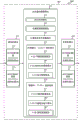
fig. 5 illustrates an exemplary set of downlink component carriers and uplink component carriers in accordance with various aspects of the present disclosure;
fig. 6 illustrates a block diagram of an apparatus for use in wireless communications, in accordance with various aspects of the disclosure;
fig. 7 illustrates a block diagram of an apparatus for use in wireless communications, in accordance with various aspects of the disclosure;
fig. 8 illustrates a block diagram of an apparatus for use in wireless communications, in accordance with various aspects of the disclosure;
fig. 9 illustrates a block diagram of a UE for use in wireless communications, in accordance with various aspects of the present disclosure;
fig. 10 illustrates a flow diagram of an example of a method for wireless communication, in accordance with various aspects of the disclosure;
fig. 11 illustrates a flow diagram of an example of a method for wireless communication, in accordance with various aspects of the disclosure;
fig. 12 illustrates a flow diagram of an example of a method for wireless communication, in accordance with various aspects of the disclosure;
fig. 13 illustrates a flow diagram of an example of a method for wireless communication, in accordance with various aspects of the disclosure;
fig. 14 illustrates a flow diagram of an example of a method for wireless communication, in accordance with various aspects of the disclosure;
fig. 15 illustrates a flow diagram of an example of a method for wireless communication, in accordance with various aspects of the disclosure;
fig. 16 illustrates a flow diagram of an example of a method for wireless communication, in accordance with various aspects of the disclosure;
fig. 17 illustrates a flow diagram of an example of a method for wireless communication, in accordance with various aspects of the disclosure; and
fig. 18 illustrates a flow diagram of an example of a method for wireless communication, in accordance with various aspects of the disclosure.
Detailed Description
Techniques are described herein for reporting channel state information of an unlicensed radio frequency spectrum band (e.g., a radio frequency spectrum band for which devices need to contend for access, since the radio frequency spectrum band is available for unlicensed use, such as a Wi-Fi radio frequency spectrum band) to a base station in a less ambiguous or unambiguous manner.
In some examples, techniques for reducing or eliminating ambiguity in channel state information reporting may include: a service is received (e.g., from a base station) via a component carrier. The component carrier may be in an unlicensed radio frequency spectrum band. In some examples, the service (or one or more other services) may also be received via one or more additional component carriers in the unlicensed radio frequency spectrum band and/or one or more component carriers in the licensed radio frequency spectrum band. Measurements may be made of one or more signals transmitted on the component carrier to estimate channel state information for the component carrier in the unlicensed radio frequency spectrum band. The channel state information is then transmitted (e.g., to a base station) in a manner that enables the channel state information to be understood (e.g., ambiguities in the nature of the channel state information can be reduced or eliminated). For example, techniques for reducing or eliminating ambiguity in channel state information may include: transmitting the channel state information regardless of whether idle channel assessment for a contention access component carrier is successful or not at a gating interval (e.g., downlink frame); enabling the base station to configure one or more reporting options (e.g., whether the UE will send the channel state information regardless of whether a successful clear channel assessment is made for contention for access to the component carrier at the gating interval; when the channel state information will be reported; etc.); the channel state information is transmitted along with an indication identifying a component carrier associated with the channel state information. These and other techniques are described in more detail with reference to fig. 5-8 and 10-18.
The techniques described herein may be used for various wireless communication systems such as CDMA, TDMA, FDMA, OFDMA, SC-FDMA and other systems. The terms "system" and "network" are often used interchangeably. A CDMA system may implement a radio technology such as CDMA2000, Universal Terrestrial Radio Access (UTRA), and so on. CDMA2000 covers IS-2000, IS-95 and IS-856 standards. IS-2000 releases 0 and A are commonly referred to as CDMA 20001X, 1X, etc. IS-856(TIA-856) IS commonly referred to as CDMA 20001 xEV-DO, High Rate Packet Data (HRPD), and so on. UTRA includes wideband CDMA (wcdma) and other CDMA variations. TDMA systems may implement wireless technologies such as global system for mobile communications (GSM). OFDMA systems may implement methods such as Ultra Mobile Broadband (UMB), evolved UTRA (E-UTRA), IEEE 802.11(Wi-Fi), IEEE 802.16(WiMAX), IEEE 802.20, Flash-OFDMTMAnd so on. UTRA and E-UTRA are universal mobile telecommunications systems(UMTS). 3GPP Long Term Evolution (LTE) and LTE-advanced (LTE-A) are releases of UMTS that employ E-UTRA. UTRA, E-UTRA, UMTS, LTE-A, and GSM are described in documents from an organization named "third Generation partnership project" (3 GPP). CDMA2000 and UMB are described in documents from an organization named "third generation partnership project 2" (3GPP 2). The techniques described herein may be used for the systems and wireless techniques mentioned above, as well as other systems and wireless techniques. However, for purposes of illustration, the following describes an LTE system, and LTE terminology is employed in much of the description below, but these techniques are applicable in addition to LTE applications.
The following description provides examples, but does not limit the scope, applicability, or examples set forth in the claims. Changes may be made in the function and arrangement of the elements discussed without departing from the spirit and scope of the disclosure. Various examples may omit, substitute, or add various procedures or components as necessary. For example, the methods described may be performed in a different order than described, with various steps added, omitted, or combined. Furthermore, features described with respect to certain examples may be combined into other examples.
Fig. 1 illustrates a block diagram of an example of a wireless communication system 100 in accordance with various aspects of the disclosure. The wireless communication system 100 may include base stations (or cells) 105, UEs 115, and a core network 130. The base stations 105 may communicate with the UEs 115 under the control of a base station controller (not shown), which may be part of the core network 130 or the base stations 105 in various examples. The base stations 105 may communicate control information and/or user data with the core network 130 over backhaul links 132. Backhaul link 132 can be a wired backhaul link (e.g., copper, fiber, etc.) and/or a wireless backhaul link (e.g., microwave, etc.). In some examples, the base stations 105 can communicate with each other directly or indirectly over backhaul links 134, where the backhaul links 134 can be wired or wireless communication links. The wireless communication system 100 may support operation on multiple carriers (waveform signals of different frequencies). Multicarrier transmitters may transmit the modulated signals simultaneously on the multiple carriers. For example, each communication link 125 may be a multi-carrier signal modulated according to various radio technologies described above. Each modulated signal may be transmitted on a different carrier and may carry control information (e.g., reference signals, control channels, etc.), overhead information, data, and so on.
Each component carrier may be provided on a licensed radio frequency band or an unlicensed radio frequency band, and a set of component carriers used in a particular communication mode may be received entirely on the licensed radio frequency band (e.g., received at UE 115), entirely on the unlicensed radio frequency band (e.g., received at UE 115), or on a combination of the licensed and unlicensed radio frequency bands (e.g., received at UE 115).
The illustrated communication links 125 in the wireless communication system 100 may include: an uplink channel (which uses component carriers) for carrying Uplink (UL) communications (e.g., transmissions from the UE115 to the base station 105) and/or a downlink channel (which uses component carriers) for carrying Downlink (DL) communications (e.g., transmissions from the base station 105 to the UE 115). UL communications or transmissions may also be referred to as reverse link communications or transmissions, while DL communications or transmissions may also be referred to as forward link communications or transmissions. Downlink communications and/or uplink communications may be implemented using licensed radio frequency spectrum bands, unlicensed radio frequency spectrum bands, or both.
In some examples, the wireless communication system 100 may be or include an LTE/LTE-a network. In an LTE/LTE-a network, the term evolved node b (enb) may be used generally to describe one or a group of base stations 105. The wireless communication system 100 may be a heterogeneous LTE/LTE-a network in which different types of enbs provide coverage for various geographic areas. For example, each eNB may provide communication coverage for a macro cell, pico cell, femto cell, and/or other types of cells. In general, a macro cell may cover a relatively large geographic area (e.g., several kilometers in radius) that allows unrestricted access by UEs 115 with service subscriptions with the network provider. In general, a pico cell may cover a relatively small geographic area that allows unrestricted access by UEs 115 with service subscriptions with the network provider. Typically, a femto cell also covers a relatively small geographic area (e.g., a home), which may provide restricted access to UEs 115 having an association with the femto cell (e.g., UEs 115 in a Closed Subscriber Group (CSG), UEs 115 for users in the home, etc.) in addition to unrestricted access. The eNB for the macro cell may be referred to as a macro eNB. An eNB for a pico cell may be referred to as a pico eNB. Also, an eNB for a femto cell may be referred to as a femto eNB or a home eNB. An eNB may support one or more (e.g., two, three, four, etc.) cells.
The wireless communication system 100 according to the LTE/LTE-a network architecture may be referred to as an Evolved Packet System (EPS). The EPS may include one or more UEs 115, evolved UMTS terrestrial radio access network (E-UTRAN), Evolved Packet Core (EPC) (e.g., core network 130), Home Subscriber Server (HSS), and operator IP services. The EPS may use other radio access technologies to interconnect with other access networks. For example, an EPS may interconnect with a UTRAN-based network and/or a CDMA-based network via one or more Serving GRPS Support Nodes (SGSNs). To support mobility and/or load balancing of the UE115, the EPS may support handover of the UE115 between a source eNB (or base station 105) and a target eNB (or base station 105). The EPS may support intra-RAT handovers between enbs and/or base stations 105 of the same RAT (e.g., other E-UTRAN networks), as well as inter-RAT handovers between enbs and/or base stations 105 of different RATs (e.g., E-UTRAN to CDMA, etc.). The EPS may provide packet switched services, however, as will be readily appreciated by those of ordinary skill in the art, the various concepts presented throughout this disclosure may be extended to networks providing circuit switched services.
The E-UTRAN may include enbs, which may provide user plane and control plane protocol terminations towards the UE 115. The enbs and/or base stations 105 may be connected to other enbs and/or base stations 105 via backhaul links 134 (e.g., X2 interface, etc.). The eNB and/or base station 105 may provide an access point for the UE115 to the EPC (e.g., core network 130). The eNB and/or base station 105 may connect to the EPC through a backhaul link 132 (e.g., S1 interface, etc.). Logical nodes in the EPC may include one or more Mobility Management Entities (MMEs), one or more serving gateways, and one or more Packet Data Network (PDN) gateways (not shown). In general, the MME may provide bearer and connection management. All user IP packets may be transported through the serving gateway, which may itself be connected to the PDN gateway. The PDN gateway may provide UE IP address allocation as well as other functions. The PDN gateway may be connected to an IP network and/or an operator's IP services. These logical nodes may be implemented in separate physical nodes, or one or more logical nodes may be combined in a single physical node. IP services of an IP network/operator may include the internet, intranets, IP Multimedia Subsystem (IMS), and/or Packet Switched (PS) streaming service (PSs).
The UE115 and eNB or base station 105 may be configured to cooperatively communicate via, for example, Multiple Input Multiple Output (MIMO), coordinated multipoint (CoMP), or other schemes. MIMO technology uses multiple antennas at the base station 105 and/or multiple antennas at the UE115 to transmit multiple data streams in a multipath environment. CoMP involves techniques for dynamically coordinating the transmission and reception of multiple enbs and/or base stations 105 to improve overall transmission quality for the UE115 and to increase network and spectrum utilization. In general, CoMP techniques may enable communication between base stations 105 using backhaul links 132 and/or 134 to coordinate control plane and user plane communications for UEs 115.
A communication network that may accommodate some of the various disclosed techniques may be a packet-based network that operates according to a layered protocol stack. In the user plane, the bearer or communication of the Packet Data Convergence Protocol (PDCP) layer may be IP-based. The Radio Link Control (RLC) layer may perform packet segmentation and reassembly for communication over logical channels. A Medium Access Control (MAC) layer may perform priority processing, logical channels being multiplexed to transport channels. The MAC layer may also provide retransmission at the MAC layer using hybrid automatic repeat request (HARQ) techniques to ensure reliable data transmission. In the control plane, a Radio Resource Control (RRC) protocol layer may provide for establishing, configuring, and maintaining an RRC connection between the UE and the network for user plane data. At the physical layer, transport channels may be mapped to physical channels.
The downlink physical channel may include at least one of a Physical Downlink Control Channel (PDCCH), a Physical HARQ Indicator Channel (PHICH), and a Physical Downlink Shared Channel (PDSCH). The uplink physical channel may include at least one of a Physical Uplink Control Channel (PUCCH) and a Physical Uplink Shared Channel (PUSCH). The PDCCH may carry Downlink Control Information (DCI), which may indicate data transmission on the PDSCH for the UE and provide the UE with a UL resource grant for the PUSCH. The UE may send control information in the PUCCH on the allocated resource blocks in the control portion. The UE may transmit only data or both data and control information in the PUSCH on the allocated resource blocks in the data portion.
LTE/LTE-A uses Orthogonal Frequency Division Multiple Access (OFDMA) on the downlink and single carrier frequency division multiple access (SC-FDMA) on the uplink. The OFDMA and/or SC-FDMA carriers may be divided into multiple (K) orthogonal subcarriers, where the subcarriers are also commonly referred to as tones, bins, and so on. Each subcarrier may be modulated with data. The spacing between adjacent subcarriers may be fixed, with the total number (K) of subcarriers depending on the system bandwidth. For example, K may be equal to 72, 180, 300, 600, 900, or 1200, respectively, for a corresponding system bandwidth of 1.4, 3, 5, 10, 15, or 20 megahertz (MHz), which has a guard band. Further, the system bandwidth may be divided into subbands. For example, one sub-band may cover 1.08MHz, and there may be 1,2, 4, 8, or 16 sub-bands.
In some examples of the wireless communication system 100, LTE/LTE-a may be deployed in different scenarios using unlicensed radio frequency spectrum bands. These deployment scenarios may include: a supplemental downlink mode in which LTE/LTE-a downlink communications in a licensed radio frequency spectrum band may be offloaded to an unlicensed radio frequency spectrum band; a carrier aggregation mode in which LTE/LTE-a downlink and uplink communications may be offloaded from a licensed radio frequency spectrum band to an unlicensed radio frequency spectrum band; standalone mode, in which LTE/LTE-a downlink and uplink communications between the eNB and/or base station and the UE may occur in unlicensed radio frequency spectrum bands. The base stations 105 and UEs 115 may support one or more of these or similar modes of operation. In the communication link 125 for LTE/LTE-a downlink communications in the licensed radio frequency band and/or the unlicensed radio frequency band, OFDMA waveforms may be used, while in the communication link 125 for LTE/LTE-a uplink communications in the licensed radio frequency band and/or the unlicensed radio frequency band, OFDMA, SC-FDMA and/or resource block interleaved FDMA waveforms may be used.
Fig. 2 illustrates a wireless communication system 200 that deploys LTE/LTE-a in different scenarios using unlicensed radio frequency spectrum bands, in accordance with various aspects of the disclosure. In particular, fig. 2 shows examples of a supplemental downlink mode, a carrier aggregation mode, and an independent mode in which LTE/LTE-a is deployed using an unlicensed radio frequency spectrum band. The wireless communication system 200 may be an example of a portion of the wireless communication system 100 described with reference to fig. 1. Further, the first base station 205 and the second base station 205-a may be examples of aspects of one or more of the base stations 105 described with reference to FIG. 1, while the first UE 215, the second UE 215-a, the third UE 215-b, and the fourth UE 215-c may be examples of aspects of one or more of the UEs 115 described with reference to FIG. 1.
In the example of a supplemental downlink mode in the wireless communication system 200, the first base station 205 may transmit an OFDMA waveform to the first UE 215 using the downlink channel 220. The downlink channel 220 may be associated with a frequency F1 in the unlicensed radio frequency spectrum band. The first base station 205 may transmit OFDMA waveforms to the first UE 215 using the first bidirectional link 225 and receive SC-FDMA waveforms from the first UE 215 using the first bidirectional link 225. The first bidirectional link 225 may be associated with a frequency F4 in a licensed radio frequency spectrum band. The downlink channel 220 in the unlicensed radio frequency spectrum band and the first bidirectional link 225 in the licensed radio frequency spectrum band may operate simultaneously. The downlink channel 220 may provide downlink capacity offload for the first base station 205. In some examples, the downlink channel 220 may be used for unicast services (e.g., addressed to one UE) or for multicast services (e.g., addressed to several UEs). This scenario may occur for any service provider (e.g., MNO) that uses a licensed radio frequency spectrum band and wishes to alleviate some of the traffic and/or signaling congestion.
In one example of a carrier aggregation mode in the wireless communication system 200, the first base station 205 may transmit an OFDMA waveform to the second UE 215-a using the second bidirectional link 230 and receive the OFDMA waveform, SC-FDMA waveform, and/or resource block interleaved FDMA waveform from the second UE 215-a using the second bidirectional link 230. The second bidirectional link 230 may be associated with a frequency F1 in the unlicensed radio frequency spectrum band. The first base station 205 may also transmit OFDMA waveforms to the second UE 215-a using the third bidirectional link 235 and receive SC-FDMA waveforms from the second UE 215-a using the third bidirectional link 235. The third bidirectional link 235 may be associated with a frequency F2 in a licensed radio frequency spectrum band. The second bidirectional link 230 may provide downlink and uplink capacity offloading for the first base station 205. Similar to the supplemental downlink described above, this scenario may occur for any service provider (e.g., MNO) that uses licensed radio spectrum and wishes to alleviate some of the traffic and/or signaling congestion.
In another example of a carrier aggregation mode in the wireless communication system 200, the first base station 205 may transmit an OFDMA waveform to the third UE 215-b using the fourth bidirectional link 240 and receive an OFDMA waveform, an SC-FDMA waveform, and/or a resource block interleaved waveform from the third UE 215-b using the fourth bidirectional link 240. The fourth bidirectional link 240 may be associated with a frequency F3 in the unlicensed radio frequency spectrum band. The first base station 205 may also transmit an OFDMA waveform to the third UE 215-b using a fifth bidirectional link 245 and receive an SC-FDMA waveform from the third UE 215-b using the fifth bidirectional link 245. The fifth bidirectional link 245 may be associated with a frequency F2 in a licensed radio frequency spectrum band. The fourth bidirectional link 240 may provide downlink and uplink capacity offload for the first base station 205. This example, and those provided above, are shown for illustration purposes only, and other similar operating modes or deployment scenarios may exist that combine LTE/LTE-a in licensed and unlicensed radio frequency bands to achieve capacity offloading.
As described above, one type of service provider that can benefit from the capacity offload that can be provided by using LTE/LTE-a in licensed radio frequency bands is a legacy MNO with access rights for LTE/LTE-a licensed radio frequency bands. For these service providers, an example of operation may include: a bootstrapping mode (e.g., supplemental downlink, carrier aggregation) using an LTE/LTE-a Primary Component Carrier (PCC) on a licensed radio frequency band and at least one Secondary Component Carrier (SCC) on an unlicensed radio frequency band.
In the carrier aggregation mode, data and control may be transmitted in, for example, a licensed radio frequency spectrum band (e.g., via first bidirectional link 225, third bidirectional link 235, and fifth bidirectional link 245), while data may be transmitted in, for example, an unlicensed radio frequency spectrum band (e.g., via second bidirectional link 230 and fourth bidirectional link 240). The carrier aggregation mechanism supported when using the unlicensed radio frequency spectrum band may fall into hybrid frequency division duplex-time division duplex (FDD-TDD) carrier aggregation or TDD-FDD carrier aggregation with different symmetries among the component carriers.
In one example of a standalone mode in the wireless communication system 200, the second base station 205-a may transmit an OFDMA waveform to the fourth UE 215-c using the bidirectional link 250 and receive the OFDMA waveform, SC-FDMA waveform, and/or resource block interleaved FDMA waveform from the fourth UE 215-c using the bidirectional link 250. The bidirectional link 250 may be associated with a frequency F3 in an unlicensed radio frequency spectrum band. The standalone mode may be used in non-legacy wireless access scenarios such as intra-venue access (e.g., unicast, multicast). Examples of types of service providers for this mode of operation may be a stadium owner, a cable company, a cable host, a hotel, a business, or a large company that does not have access to licensed radio frequency bands.
In some examples, a transmitting device (e.g., one of base stations 105 and/or 205 described with reference to fig. 1 and/or 2, and/or one of UE115 and/or UE 215 described with reference to fig. 1 and/or 2) may use a gating interval to gain channel access to an unlicensed radio frequency spectrum band (e.g., a physical channel of the unlicensed radio frequency spectrum band). The gating interval may specify the application of a contention-based protocol, for example, an LBT protocol based on the LBT protocol specified in ETSI (EN 301893). When a gating interval is used that specifies the application of the LBT protocol, the gating interval may indicate when the transmitting apparatus needs to perform CCA. The result of the CCA may indicate to the transmitting apparatus whether a channel of the unlicensed radio frequency spectrum band is available or in use during the gating interval (which is also referred to as an LBT frame). When the CCA indicates that the channel is available (e.g., using "clear") during a corresponding LBT frame, the transmitting apparatus may reserve and/or use the channel of the unlicensed radio frequency spectrum band during a portion or all of the LBT frame. When the CCA indicates that the channel is unavailable (e.g., the channel is used or reserved by another apparatus), the transmitting apparatus is prevented from using the channel during the LBT frame.
In some cases, it is useful for the transmitting device to generate the gating interval on a periodic basis and synchronize at least one boundary of the gating interval with at least one boundary of the periodic frame structure. For example, it may be useful to generate a periodic gating interval for a cellular downlink in an unlicensed radio frequency spectrum band and synchronize at least one boundary of the periodic gating interval with at least one boundary of a periodic frame structure (e.g., a periodic LTE/LTE-a radio frame structure) associated with the cellular downlink. In fig. 3, an example of such synchronization is shown.
Fig. 3 illustrates an example 300 of a gating interval (or LBT frame) for a cellular downlink in an unlicensed radio frequency spectrum band, in accordance with various aspects of the present disclosure. An eNB supporting transmission on an unlicensed radio frequency spectrum band may use the first gating interval 305, the second gating interval 315, and/or the third gating interval 325 as periodic gating intervals. Examples of the eNB may include the base station 105 and/or 205 described with reference to fig. 1 and/or 2. The first gating interval 305, the second gating interval 315, and/or the third gating interval 325 may be used in conjunction with the wireless communication systems 100 and/or 200 described with reference to fig. 1 and/or 2.
By way of example, the duration of the first gating interval 305 is shown to be equal to (or approximately equal to) the duration of the LTE/LTE-a radio frame 310 of the periodic frame structure associated with the cellular downlink. In some examples, "approximately equal" means that the duration of the first gating interval 305 is within a Cyclic Prefix (CP) time of the duration of the periodic frame structure.
At least one boundary of the first gating interval 305 may be synchronized with at least one boundary of a periodic frame structure including LTE/LTE-a radio frames N-1 to N + 1. In some cases, the first gating interval 305 may have a boundary that is aligned with a frame boundary of the periodic frame structure. In other cases, the first gating interval 305 may have boundaries that are synchronized with, but offset from, the frame boundaries of the periodic frame structure. For example, the boundaries of the first gating interval 305 may be aligned with sub-frame boundaries of a periodic frame structure or with sub-frame midpoint boundaries of a periodic frame structure (e.g., a midpoint of a particular sub-frame).
In some cases, the periodic frame structure may include LTE/LTE-A radio frames N-1 to N + 1. Each LTE/LTE-a radio frame 310 may have a duration of, for example, ten milliseconds, and the first gating interval 305 may also have a duration of ten milliseconds. In these cases, the boundary of the first gating interval 305 may be synchronized with a boundary (e.g., a frame boundary, a subframe boundary, or a subframe midpoint boundary) of one of the LTE/LTE-a radio frames (e.g., LTE/LTE-a radio frame (N)).
For example, the duration of the second gating interval 315 and the third gating interval 325 are shown as being a sub-multiple (or an approximate sub-multiple thereof) of the duration of the periodic frame structure associated with the cellular downlink. In some examples, an "approximate sub-multiple" means that the duration of the second gating interval 315 and/or the third gating interval 325 is within a Cyclic Prefix (CP) time of a sub-multiple (e.g., half or one-tenth) of the duration of the periodic frame structure. For example, the second gating interval 315 may have a duration of five milliseconds and the third gating interval 325 may have a duration of two milliseconds. The second gating interval 315 and the third gating interval 325 are advantageous over the first gating interval 305 because their shorter duration helps to share the unlicensed radio frequency spectrum band more frequently.
Fig. 4A illustrates an example 400 of wireless communication 410 over an unlicensed radio frequency spectrum band, in accordance with various aspects of the present disclosure. TDD frame 415 (which may correspond to an LBT gating interval) may have a duration of 10 milliseconds and include multiple downlink subframes 420, multiple uplink subframes 425, and two types of special subframes (S subframes 430 and S' subframes 435). The S subframe 430 may provide a transition between the downlink subframe 420 and the uplink subframe 425, while the S' subframe 435 may provide a transition between the uplink subframe 425 and the downlink subframe 420. During the S' subframe 435, one or more base stations (e.g., one or more of the base stations 105 and/or 205 described with reference to fig. 1 and/or 2) may perform a Downlink Clear Channel Assessment (DCCA)440 to reserve a channel for which wireless communication 410 occurs for a period of time. After the base station has performed a successful DCCA 440, the base station may transmit a Channel Usage Beacon Signal (CUBS)445 to provide an indication to other base stations and/or devices that the base station has subscribed to the channel.
The S' subframe 435 may include 14 OFDM symbols, numbered 0 through 13 in fig. 4A. The base station may use the first portion of the S' subframe 435 (symbols 0 to 5 in this example) as a silent DL period, which needs to be compatible with the LTE/LTE-a communication standard. Thus, the base station does not transmit data during the silent DL period, but the UE may transmit a certain amount of uplink data during the silent DL period. The second part of the S' subframe 435 may be used for DCCA 440. In this example 400, the S' subframe 435 includes seven DCCA slots, which are included in symbols 6 through 12. The use of DCCA timeslots by different network operators may be coordinated to provide more efficient system operation. In some examples, to determine which of the seven possible DCCA slots to use to perform the DCCA procedure, the base station 105 may evaluate a mapping function of the form:
FD(GroupID,t)∈{1,2,3,4,5,6,7}
where GroupID is a "deployment group ID" assigned to the base station 105, and t is an LBT frame number corresponding to a gating interval or frame in which DCCA is performed.
Fig. 4B illustrates an example 450 of wireless communication 455 over an unlicensed radio frequency spectrum band, in accordance with various aspects of the present disclosure. TDD frame 415 (which may correspond to the LBT frame period of fig. 4A, which may correspond to the LBT fixed frame period) may include a plurality of downlink subframes 420, a plurality of uplink subframes 425, and two types of special subframes (S subframes 530 and S' subframes 435). As discussed above, the S subframe 430 may provide a transition between the downlink subframe 420 and the uplink subframe 425, while the S' subframe 435 may provide a transition between the uplink subframe 425 and the downlink subframe 420. During the S subframe 430, one or more UEs (e.g., one or more of the UEs 115 and/or 215 described above with reference to fig. 1 and/or 2) may perform an uplink cca (ucca)465 to reserve a channel for which wireless communication 455 occurs for a period of time. After the UE has made a successful UCCA465, the UE may transmit a Channel Usage Beacon Signal (CUBS)470 to provide an indication to other UEs and/or devices that the UE has subscribed to the channel.
The S subframe 430 may include 14 OFDM symbols, numbered 0 through 13 in fig. 4B. A first portion of the S subframe 430 (in this example, symbols 0 to 3) may be used as a downlink pilot time slot (DwPTS)475, and a second portion of the S subframe 430 may be used as a Guard Period (GP) 480. A third portion of S subframe 430 may be used for UCCA 465. In this example 450, S subframe 430 includes seven U-LBT slots that are included in symbols 6 through 12. The use of U-LBT slots by different UEs may be coordinated to provide more efficient system operation. In some examples, to determine which of the seven possible UCCA slots to use for UCCA, the UE may evaluate a mapping function of the form:
FU(GroupID,t)∈{1,2,3,4,5,6,7}
where GroupID is a "deployment group ID" assigned to the UE, and t is an LBT frame number corresponding to a frame in which UCCA is performed.
The mapping functions for DCCA and/or UCCA may be constructed based on different criteria depending on whether the mapping functions will have orthogonal or non-orthogonal properties. In the example with orthogonal LBT access, the mapping function may have orthogonal properties according to:
FD/U(x,t)≠FD/U(y,t)
GroupID x,y∈{1,2,3,4,5,6,7}
for all times t, as long as x ≠ y, different group IDs are represented. In this case, base stations and/or UEs having different group IDs may perform CCA during non-overlapping LBT time intervals. A base station or UE with a group ID mapped to an earlier LBT slot may secure the channel for a period of time without interference. According to various deployments, the mapping function is fair, mapping { F } between different time indices tD/U(x, t), t ═ 1,2,3, … } varies such that different group IDs have the same probability of mapping to earlier LBT slots over a suitably longer time interval (thus, securing the channel without other interference).
All base stations and UEs deployed by the same network operator/service provider may be assigned the same group ID so that they do not preempt each other in the contention process. This allows full frequency reuse between base stations and UEs of the same deployment, which may result in enhanced system throughput. Different deployed base stations and/or UEs may be assigned different group IDs such that access to the channel is mutually exclusive in the case of orthogonal CCA slot mapping.
In examples with non-orthogonal or overlapping CCA slot access, the mapping function may allow more than seven group IDs. For example, in some cases it is useful to support more than seven deployment group IDs, but in this case the orthogonal properties of the CCA slot mapping function cannot be maintained. In these cases, it is desirable to reduce the frequency of collisions between any two group IDs. In some examples, non-orthogonal CCA slot mapping sequences may also be used in order to provide fair channel access between deployments that do not have close coordination with respect to LBT opportunities. An example of a non-orthogonal CCA slot mapping sequence is given by:
FD/U(x,t)=R1,7(x,t)
GroupID x=∈{1,2,...216}
wherein R is1,7(x, t) is a pseudo-random number generator between 1 and 7 independently selected for GroupID x. In this case, there is a potential collision between base stations and/or UEs of different GroupID in the same LBT frame t.
Accordingly, LBT slots may be selected according to the stated mapping function and used for D-LBT 540 and/or U-LBT 565.
Some communication modes with a UE may require communication on multiple channels (i.e., component carriers), where each channel is established between the UE and one of multiple cells (e.g., serving cells, which may be different base stations in some cases) using different component carriers. In some examples, two or more cells may use different carrier frequencies or component carriers, as may be found in carrier aggregation and/or dual connectivity (e.g., multi-flow) communication modes. In other examples, two or more cells may have the same carrier frequency (e.g., component carrier), as may be found in a coordinated multipoint (CoMP) communication mode. In any event, each component carrier may be used on a licensed based radio frequency spectrum band and/or an unlicensed radio frequency spectrum band, and a group of component carriers involved in a particular communication mode may all be received on the licensed radio frequency spectrum band, all be received on the unlicensed radio frequency spectrum band, or be received on a combination of the licensed radio frequency spectrum band and the unlicensed radio frequency spectrum band. To establish communications using a component carrier on an unlicensed radio frequency spectrum band, a CCA may be performed to contend for access to the unlicensed radio frequency spectrum band. When the CCA is successful, the component carrier may be used for communication in an unlicensed radio frequency spectrum band. When the LBT procedure fails, the component carrier may not be used.
Fig. 5 illustrates an exemplary set 500 of downlink component carriers 505 and uplink component carriers 510 in accordance with various aspects of the disclosure. Specifically, by way of example, fig. 5 shows five Downlink (DL) Component Carriers (CCs) 505 and five Uplink (UL) CCs 510. The DL CC505 includes a DL primary component carrier (DL PCC)505-a, a first secondary component carrier (DL SCC)505-b, a second DL SCC 505-c, a third DL SCC 505-d, and a fourth DL SCC 505-e. Similarly, UL CC510 includes UL PCC510-a, first UL SCC 510-b, second UL SCC 510-c, third UL SCC 510-d, and fourth UL SCC 510-e. For networks such as LTE/LTE-a networks, UL PCC510-a may carry PUCCH; each of the UL PCC510-a, the first UL SCC 510-b, the second UL SCC 510-c, the third UL SCC 510-d, and the fourth UL SCC 510-e may carry a PUSCH. In some examples, uplink control information such as acknowledgement and negative acknowledgement (ACK/NAK), Channel State Information (CSI), and/or Scheduling Request (SR) control information may be transmitted on the PUCCH.
In some examples, each of the DL PCC505-a, the first DL SCC505-b, the second DL SCC 505-c, the third DL SCC 505-d, and the fourth DL SCC 505-e may be mapped to the UL PCC510-a to report uplink control information for a first cell corresponding to the DL PCC505-a, a second cell corresponding to the first DL SCC505-b, a third cell corresponding to the second DL SCC 505-c, a fourth cell corresponding to the third DL SCC 505-d, and a fifth cell corresponding to the fourth DL SCC 505-e. To reduce the overhead of the PUCCH carried on the UL PCC510-a, the PUCCH may be configured such that uplink control information for each of the first, second, third, fourth, and fifth cells is reported using resources (e.g., shared resources such as one or more OFDM symbols) in an uplink subframe of the UL PCC 510-a. Therefore, there may be a collision of resources in the uplink subframe. To resolve the conflict, reporting of uplink control information for each of the first, second, third, fourth, and fifth cells may be prioritized such that uplink control information for one of the first, second, third, fourth, and fifth cells is transmitted during a particular instance of the resource.
In systems where data and control information is transmitted from a plurality of cells to a UE (e.g., using different component carriers) over a set of DL CCs, such as DL CC505, and data and control information is transmitted from the UE to one or more of the base stations corresponding to the plurality of cells over a set of UL CCs, such as UL CC510, periodic uplink control information reporting and/or aperiodic uplink control information reporting may be supported. In an example of periodic uplink control information reporting in carrier aggregation mode, reporting of uplink control information may be prioritized based on a priority level of a reporting type of CSI.
In some examples, the priority levels for the reporting types of CSI may include: a highest priority level (e.g., a reporting type of 3, 5, 6, or 2 a) when a reporting type of CSI includes a Rank Indicator (RI), a Precoding Type Indicator (PTI), or a wideband Precoding Matrix Indicator (PMI); a medium priority level (e.g., a reporting type of 2, 2b, 2c, or 4) when the reporting type of the CSI includes at least one of a wideband Channel Quality Indicator (CQI) or a wideband CQI with PMI; and/or a low priority level (e.g., reporting type of 1, 1 a) when the reporting type of CSI includes subband CQI or subband CQI with PMI. When the priority levels of the reporting types of the CSI are the same for two or more cells, the priority for reporting the uplink control information may be determined based on a comparison of the serving cell indexes of the colliding cells. For example, cells with lower cell indices may be given higher priority than cells with higher cell indices. The serving cell indexes corresponding to a plurality of cells may be configured on a UE-by-UE basis. The same priority rule may be applied regardless of whether PUSCH is transmitted or not.
After prioritizing the reporting of uplink control information for the plurality of cells, the conflicting resources may be used for reporting for uplink control information for the cell associated with the highest priority, discarding uplink control information for the remaining cells.
In the example of aperiodic uplink control information reporting in carrier aggregation mode, reporting of uplink control information may be prioritized based on the state of a two-bit CSI request field, where a "00" state may indicate that CSI should not be reported; the "01" state may indicate uplink control information for the cell/DL CC505, which is system information block 2(SIB2) linked to the UL PCC 510-a; the "10" and "11" states may indicate that the priority of reporting of uplink control information for a plurality of cells is configured by Radio Resource Control (RRC). For a common search space, a "0" state may indicate that no CSI should be reported; the "1" state may indicate that the priority of reporting of uplink control information for a plurality of cells is configured by RRC. The RRC may prioritize reports for any combination of up to five component carriers.
In the example of aperiodic uplink control information reporting in CoMP mode, for the case where two or more CSI processes are specified (where each CSI process is associated with a particular transmission point involved in CoMP), reporting of uplink control information may be prioritized based on a two-bit CSI request field, where a "00" state may indicate that CSI should not be reported; the "01" state may indicate that the priority of reporting of uplink control information for a plurality of cells is configured by RRC, wherein RRC-configured CSI processing is restricted to a given cell; the "10" and "11" states may indicate that the priority of reporting of uplink control information for a plurality of cells is configured by RRC. For a common search space, a "0" state may indicate that no CSI should be reported; the "1" state may indicate that the priority of reporting of uplink control information for a plurality of cells is configured by RRC. The RRC may prioritize reports for any combination of up to five component carriers.
Now consider a set of DL CCs such as DL CC505 shown in fig. 5. In one example, a first DL CC (e.g., DL PCC 505-a) transmits over a licensed radio frequency spectrum band (e.g., a radio frequency spectrum band that devices do not contend for access because the spectrum band is licensed for a particular use by a particular user). A second DL CC (e.g., DL SCC 505-b) transmits over an unlicensed radio frequency spectrum band (e.g., a radio frequency spectrum band that devices need to contend for access because it is available for unlicensed use, such as a Wi-Fi radio frequency spectrum band). Since the DL PCC is assigned a serving cell index of "0" (i.e., the lowest serving cell index), in some examples, the cell associated with the DL PCC505-a will be given priority based on the priority level of the reporting type of CSI at any time when there is a conflict. The use in connection with an unlicensed radio frequency spectrum band depends on the fact that it is contended for access to the unlicensed radio frequency spectrum band via the LBT procedure (and thus is opportunistic), which means that reporting of uplink control information for the cell associated with the DL SCC505-b is infrequent or, in some cases, may be effectively blocked. However, due to the dynamic nature of competing for access to the unlicensed radio frequency spectrum band, uplink control information for cells using CCs on the unlicensed radio frequency spectrum band may be more valuable (especially when there is a longer period of continuous failed clear channel assessment). Thus, in some examples, it may be useful to prioritize reporting of uplink control information based at least in part on whether a cell uses an unlicensed radio frequency spectrum band for shared resources of an uplink subframe.
When the clear channel assessment performed by the base station does not win contention for access to the unlicensed radio frequency spectrum band, there may be no signal or signals transmitted to estimate channel state information for the component carrier in the unlicensed radio frequency spectrum band (e.g., there may be no valid measurement subframes). In the case of periodic CSI reporting, the UE may estimate and/or report channel state information based on measurements obtained in the last valid subframe (e.g., measurements of the last subframe for which idle channel assessment performed by the base station was successful). However, in the case of aperiodic CSI reporting, the event-driven nature of aperiodic CSI reporting requires buffering of measurements (or measurement subframes) to estimate channel state information. Since aperiodic CSI reporting is event-driven, measurements obtained for the last valid subframe need to be buffered for an indeterminate duration (e.g., until the base station wins contention for access to a component carrier of the unlicensed radio frequency spectrum band).
When the clear channel assessment performed by the base station is successful, but the UE incorrectly determines that it failed, the UE may assume that there are no one or more signals transmitted to estimate the channel state information for that component carrier in the unlicensed radio frequency spectrum band (e.g., there are no valid measurement subframes).
In one example, there may be ambiguity at the base station as to whether and/or when CSI is reported, as well as ambiguity as to the component carrier for which the CSI is reported (i.e., there is misalignment of the base station with respect to the UE's CSI report). This ambiguity may be due to a failure of the clear channel assessment performed by the base station. This ambiguity may also be due to the UE incorrectly determining that the clear channel assessment performed by the base station was successful or failed (in fact, the clear channel assessment was not successful or failed). Moreover, such ambiguity may also be the result of the UE reporting different types of CSI (or not reporting CSI) based on determining that the clear channel assessment performed by the base station was successful or failed. Various misalignment issues of the eNB with respect to aperiodic CSI reports of the UE and periodic CSI reports of the UE will be described below.
As a first example of a misalignment problem of a base station with respect to aperiodic channel state information reports, consider that for a downlink subframe, a UE incorrectly determines that a clear channel assessment failed for accessing a component carrier in an unlicensed radio frequency spectrum band. Since the UE determines that the clear channel assessment failed, the UE may omit reporting aperiodic channel state information associated with the component carrier in the unlicensed radio frequency spectrum band. However, since this clear channel assessment performed by the base station is successful, the base station may expect a report of aperiodic channel state information (assuming the base station dynamically requests a report of aperiodic channel state information). This represents a misalignment problem. As a second example of the misalignment problem, consider aperiodic channel state information reported on PUSCH along with an uplink shared channel (UL-SCH). Since this aperiodic channel state information can be multiplexed with the UL-SCH by partitioning the available PUSCH resources, the base station may not be able to discern which PUSCH resources are allocated to the aperiodic channel state information and which resources are allocated to the UL-SCH. This represents a misalignment problem. In some cases, the base station may attempt blind detection of resource allocations for aperiodic channel state information and UL-SCH. Such blind detection may or may not be successful. As a third example of the misalignment problem, consider that only aperiodic channel state information is transmitted in the presence of multiple component carriers (e.g., a primary component carrier and one or more secondary component carriers). The base station may not be able to determine the number or identity of component carriers to which the aperiodic channel state information applies. This represents a misalignment problem.
As a first example of the misalignment problem of the base station with respect to the aperiodic channel state information report, consider that the UE incorrectly determines that the clear channel assessment failed for a downlink subframe for a component carrier in the unlicensed radio frequency spectrum band. Since the UE determines that the clear channel assessment failed, the UE may omit reporting periodic channel state information or periodic channel state information for component carriers in the licensed radio frequency spectrum band. However, since this clear channel assessment performed by the base station is successful, the base station may desire periodic channel state information reports for component carriers in the unlicensed radio frequency spectrum band. While a base station receiving periodic channel state information from a UE may attempt blind detection to determine whether the periodic channel state information corresponds to a component carrier in an unlicensed radio frequency spectrum band or a component carrier in a licensed radio frequency spectrum band, such blind detection may not be successful (e.g., particularly when the bit width of the periodic channel state information for the unlicensed radio frequency spectrum band is the same as the bit width of the periodic channel state information for the licensed radio frequency spectrum band). This represents a misalignment problem.
Fig. 6 illustrates a block diagram 600 of an apparatus 605 for use in wireless communications, in accordance with various aspects of the disclosure. In some examples, the apparatus 605 may be an example of aspects of one or more of the UEs 115 and/or 215 described with reference to fig. 1 and/or 2. The apparatus 605 may also be a processor. The apparatus 605 may include a receiver module 610, a wireless communication management module 620, and/or a transmitter module 630. Each of these components may communicate with each other.
These components in the apparatus 605 may be implemented individually or collectively using one or more Application Specific Integrated Circuits (ASICs) adapted to perform some or all of the applicable functions in hardware. Alternatively, the functions may be performed by one or more other processing units (or cores), on one or more integrated circuits. In other examples, other types of integrated circuits may be used (e.g., structured/platform ASICs, Field Programmable Gate Arrays (FPGAs), and other semi-custom ICs), where these integrated circuits may be programmed in any manner known in the art. Further, the functions of each unit may also be implemented, in whole or in part, using instructions embodied in a memory, formatted to be executed by one or more general or special purpose processors.
In some examples, the receiver module 610 may include at least one Radio Frequency (RF) receiver, e.g., at least one RF receiver operable to receive a licensed radio frequency band (e.g., a radio frequency band to which a device is not licensed for a particular use due to the spectrum band being licensed for a particular user) and/or an unlicensed radio frequency band (e.g., a radio frequency band to which a device needs to contend for access due to the radio frequency band being available for transmission over unlicensed use (e.g., a Wi-Fi radio frequency band and/or another unlicensed radio frequency band)). In some examples, both the licensed radio frequency spectrum band and the unlicensed radio frequency spectrum band may be used for LTE/LTE-a communications, e.g., as described with reference to fig. 1 and/or 2. The receiver module 610 may be used to receive various types of data and/or control signals (i.e., transmissions) over one or more communication links of a wireless communication system, such as one or more communication links of the wireless communication systems 100 and/or 200 described with reference to fig. 1 and/or 2. These communication links may be established over a licensed radio frequency spectrum band and/or an unlicensed radio frequency spectrum band.
In some examples, the transmitter module 630 may include at least one RF transmitter, e.g., at least one RF transmitter operable to transmit signals on a licensed radio frequency band and/or an unlicensed radio frequency band. The transmitter module 630 may be used to transmit various types of data and/or control signals (i.e., transmissions) over one or more communication links of a wireless communication system, such as one or more communication links of the wireless communication systems 100 and/or 200 described with reference to fig. 1 and/or 2. These communication links may be established over a licensed radio frequency spectrum band and/or an unlicensed radio frequency spectrum band.
In some examples, the wireless communication management module 620 may be configured to receive service via one or more component carriers, wherein at least one of the component carriers is in an unlicensed radio frequency spectrum band. Further, the wireless communication management module 620 may be further configured to make measurements on one or more signals associated with at least one of the component carriers to estimate channel state information for at least one component carrier in the unlicensed radio frequency spectrum band. The channel state information may then be transmitted (e.g., to a base station) in a manner that enables the channel state information to be understood (e.g., in a manner that reduces or eliminates ambiguity in the nature of the channel state information). For example, techniques for reducing or removing ambiguity in channel state information may include: transmitting the channel state information even when it is determined that a clear channel assessment for a downlink subframe for one component carrier fails; enabling the base station to explicitly configure what channel state information is to be transmitted at that time; or transmitting the channel state information and an indication identifying a component carrier associated with the channel state information. These and other techniques are described in more detail with reference to fig. 7, 8, and 10-18.
Fig. 7 illustrates a block diagram 700 of an apparatus 705 for use in wireless communications, in accordance with various aspects of the disclosure. In some examples, the apparatus 705 may be an example of aspects of one or more of the UEs 115 and/or 215 described with reference to fig. 1 and/or 2, and/or an example of aspects of the apparatus 605 described with reference to fig. 6. The apparatus 705 may also be a processor. The apparatus 705 may include a receiver module 710, a wireless communication management module 720, and/or a transmitter module 730. Each of these components may communicate with each other.
These components in the apparatus 705 may be implemented individually or collectively using one or more ASICs adapted to perform some or all of these applicable functions in hardware. Alternatively, the functions may be performed by one or more other processing units (or cores), on one or more integrated circuits. In other examples, other types of integrated circuits (e.g., structured/platform ASICs, FPGAs, and other semi-custom ICs) may be used, wherein the integrated circuits may be programmed in any manner known in the art. Further, the functions of each unit may also be implemented, in whole or in part, using instructions embodied in a memory, formatted to be executed by one or more general or special purpose processors.
In some examples, receiver module 710 may include at least one RF receiver, e.g., at least one RF receiver operable to receive a licensed radio frequency spectrum band (e.g., a radio frequency spectrum band that a device is not licensed to a particular user for a particular use) and/or an unlicensed radio frequency spectrum band (e.g., a radio frequency spectrum band that a device needs for contention access because the radio frequency spectrum band is available for transmissions over unlicensed use (e.g., a Wi-Fi radio frequency spectrum band)). In some examples, both the licensed radio frequency spectrum band and the unlicensed radio frequency spectrum band may be used for LTE/LTE-a communications, e.g., as described with reference to fig. 1 and/or 2. In some cases, receiver module 710 may include separate receivers for licensed and unlicensed radio frequency bands. In some examples, these separate receivers may take the form of a licensed RF band LTE/LTE-a receiver module 712 for communicating over a licensed radio frequency band and an unlicensed RF band LTE/LTE-a receiver module 714 for communicating over an unlicensed radio frequency band. The receiver module 710 (which includes the licensed RF band LTE/LTE-a receiver module 712 and/or the unlicensed RF band LTE/LTE-a receiver module 714) may be used to receive various types of data and/or control signals (i.e., transmissions) over one or more communication links of a wireless communication system (e.g., one or more communication links of the wireless communication system 100 and/or 200 described with reference to fig. 1 and/or 2). These communication links may be established over a licensed radio frequency spectrum band and/or an unlicensed radio frequency spectrum band.
In some examples, transmitter module 730 may include at least one RF transmitter, e.g., at least one RF transmitter operable to transmit signals on a licensed radio frequency spectrum band and/or an unlicensed radio frequency spectrum band. In some cases, transmitter module 730 may include separate transmitters to correspond to the licensed radio frequency spectrum band and the unlicensed radio frequency spectrum band. In some examples, these separate transmitters may take the form of a licensed RF band LTE/LTE-a transmitter module 732 for communicating over a licensed radio frequency band and an unlicensed RF band LTE/LTE-a transmitter module 734 for communicating over an unlicensed radio frequency band. The transmitter module 730 (which includes the licensed RF band LTE/LTE-a transmitter module 732 and/or the unlicensed RF band LTE/LTE-a transmitter module 734) may be used to transmit various types of data and/or control signals (i.e., transmissions) over one or more communication links of a wireless communication system (e.g., one or more communication links of the wireless communication system 100 and/or 200 described with reference to fig. 1 and/or 2). These communication links may be established over a licensed radio frequency spectrum band and/or an unlicensed radio frequency spectrum band.
In some examples, the wireless communication management module 720 may be an example of one or more aspects of the wireless communication management module 620 described with reference to fig. 6. The wireless communication management module 720 may include a component carrier management module 735 and/or a component carrier signal measurement module 740. Each of these components may communicate with each other.
In some examples, component carrier management module 735 may be used to receive service via component carriers (e.g., from a base station). The component carrier may be in an unlicensed radio frequency spectrum band. In some examples, the service (or one or more other services) may be received via one or more additional component carriers in the unlicensed radio frequency spectrum band and/or one or more component carriers in the licensed radio frequency spectrum band.
In some examples, component carrier signal measurement module 740 may be configured to measure one or more signals transmitted on the component carrier to estimate channel state information for the component carrier in the unlicensed radio frequency spectrum band.
Fig. 8 illustrates a block diagram 800 of an apparatus 805 for use in wireless communications, in accordance with various aspects of the disclosure. In some examples, the apparatus 805 may be an example of aspects of one or more of the UEs 115 and/or 215 described with reference to fig. 1 and/or 2, and/or aspects of the apparatuses 605 and/or 705 described with reference to fig. 6 and/or 7. The apparatus 805 may also be a processor. The apparatus 805 may include a receiver module 810, a wireless communication management module 820, and/or a transmitter module 830. Each of these components may communicate with each other.
These components in the apparatus 805 may be implemented individually or collectively using one or more ASICs adapted to perform some or all of these applicable functions in hardware. Alternatively, the functions may be performed by one or more other processing units (or cores), on one or more integrated circuits. In other examples, other types of integrated circuits (e.g., structured/platform ASICs, FPGAs, and other semi-custom ICs) may be used, wherein the integrated circuits may be programmed in any manner known in the art. Further, the functions of each unit may also be implemented, in whole or in part, using instructions embodied in a memory, formatted to be executed by one or more general or special purpose processors.
In some examples, the receiver module 810 may include at least one RF receiver, e.g., at least one RF receiver operable to receive a licensed radio frequency spectrum band (e.g., a radio frequency spectrum band that a device is not licensed to a particular user for a particular use) and/or an unlicensed radio frequency spectrum band (e.g., a radio frequency spectrum band that a device needs for contention access because the radio frequency spectrum band is available for transmissions over unlicensed use (e.g., a Wi-Fi radio frequency spectrum band)). In some examples, both the licensed radio frequency spectrum band and the unlicensed radio frequency spectrum band may be used for LTE/LTE-a communications, e.g., as described with reference to fig. 1 and/or 2. In some cases, the receiver module 810 may include separate receivers to correspond to the licensed radio frequency spectrum band and the unlicensed radio frequency spectrum band. In some examples, these separate receivers may take the form of a licensed RF band LTE/LTE-a receiver module 812 for communicating over a licensed radio frequency band and an unlicensed RF band LTE/LTE-a receiver module 814 for communicating over an unlicensed radio frequency band. The receiver module 810 (which includes the licensed RF band LTE/LTE-a receiver module 812 and/or the unlicensed RF band LTE/LTE-a receiver module 814) may be used to receive various types of data and/or control signals (i.e., transmissions) over one or more communication links of a wireless communication system (e.g., one or more communication links of the wireless communication system 100 and/or 200 described with reference to fig. 1 and/or 2). These communication links may be established over a licensed radio frequency spectrum band and/or an unlicensed radio frequency spectrum band.
In some examples, transmitter module 830 may include at least one RF transmitter, e.g., at least one RF transmitter operable to transmit signals on a licensed radio frequency spectrum band and/or an unlicensed radio frequency spectrum band. In some cases, transmitter module 830 may include separate transmitters to correspond to the licensed radio frequency spectrum band and the unlicensed radio frequency spectrum band. In some examples, these separate transmitters may take the form of a licensed RF band LTE/LTE-a transmitter module 832 for communicating over a licensed radio frequency band and an unlicensed RF band LTE/LTE-a transmitter module 834 for communicating over an unlicensed radio frequency band. The transmitter module 830 (which includes the licensed RF band LTE/LTE-a transmitter module 832 and/or the unlicensed RF band LTE/LTE-a transmitter module 834) may be used to transmit various types of data and/or control signals (i.e., transmissions) over one or more communication links of a wireless communication system (e.g., one or more communication links of the wireless communication systems 100 and/or 200 described with reference to fig. 1 and/or 2). These communication links may be established over a licensed radio frequency spectrum band and/or an unlicensed radio frequency spectrum band.
In some examples, wireless communication management module 820 may be an example of one or more aspects of wireless communication management modules 620 and/or 720 described with reference to fig. 6 and/or 7. Wireless communication management module 820 may include a DCCA analysis module 835, a component carrier management module 840, a component carrier signal measurement module 845, an aperiodic CSI (a-CSI) reporting module 850, and/or a periodic CSI (P-CSI) module 870. Each of these components may communicate with each other.
In some examples, DCCA analysis module 835 may be used to determine whether a clear channel assessment for a downlink subframe corresponding to a component carrier in an unlicensed radio frequency spectrum band fails. In some examples, DCCA analysis module 835 may determine whether a clear channel assessment has failed based at least in part on the channel usage beacon signal, a reference signal for channel state information reporting, and/or other information received for downlink frames (some or all of which may be received from a base station over a component carrier in an unlicensed radio frequency spectrum band).
In some examples, component carrier management module 840 may be used to receive service via a component carrier (e.g., from a base station). The component carrier may be in an unlicensed radio frequency spectrum band. In some examples, the service (or one or more other services) may also be received via one or more additional component carriers in the unlicensed radio frequency spectrum band and/or one or more component carriers in the licensed radio frequency spectrum band.
In some examples, component carrier signal measurement module 845 may be configured to measure one or more signals transmitted on at least one component carrier to estimate channel state information for the component carrier in the unlicensed radio frequency spectrum band. Alternatively or additionally, the component carrier signal measurement module 845 may be used to measure one or more signals transmitted on at least one component carrier in the licensed radio frequency spectrum band.
In some examples, a-CSI reporting module 850 may be configured to transmit channel state information aperiodically (e.g., to a base station). For example, in a first mode of operation of apparatus 805, component carrier management module 840 may be configured to receive service via a component carrier (e.g., from a base station). The component carrier may be in an unlicensed radio frequency spectrum band. The DCCA analysis module 835 may be used to determine whether the clear channel assessment for the downlink frame of the component carrier failed. Upon determining that the clear channel assessment for the downlink frame corresponding to the component carrier is successful, the component carrier signal measurement module 845 may be configured to measure one or more signals transmitted on the component carrier to estimate channel state information of the component carrier in the unlicensed radio frequency spectrum band. The a-CSI reporting module 850 may then be configured to transmit or not transmit channel state information aperiodically according to a default reporting rule (e.g., as described with reference to fig. 5). Upon determining that the clear channel assessment failed for accessing a component carrier in the unlicensed radio frequency spectrum band for the downlink frame, component carrier signal measurement module 845 may be to: 1) obtaining measurements for one or more historical signals transmitted on the component carrier to estimate channel state information for the component carrier in the unlicensed radio frequency spectrum band (e.g., obtaining measurements based on measurements for one or more historical signals associated with the component carrier to estimate channel state information); or 2) making measurements of one or more current signals transmitted on the component carrier to estimate channel state information for the component carrier in the unlicensed radio frequency spectrum band. The one or more signals may be measured during a downlink frame of the component carrier. a-CSI reporting module 850 and/or a-CSI semi-static configuration module 855 may then be used to aperiodically transmit channel state information for the component carrier.
In an aspect, the first mode of operation of the apparatus 805 may be useful because the aperiodic transmission of channel state information does not depend on whether the UE correctly determines that the clear channel assessment failed. This may provide better alignment between a base station and a UE communicating over component carriers, but at the cost of higher overhead (especially when the serving cell or set of cells for a component carrier in the unlicensed radio frequency spectrum band has a higher probability of a failed clear channel assessment). In some examples, a base station that receives channel state information sent by the apparatus 805 may discard channel state information that is not useful (e.g., because it corresponds to an actual failed clear channel assessment).
In a second mode of operation of apparatus 805, component carrier management module 840 may be configured to receive service via a component carrier (e.g., from a base station). The component carrier may be in an unlicensed radio frequency spectrum band. The DCCA analysis module 835 may be used to determine whether the clear channel assessment of the downlink frame fails for the component carrier. Upon determining that the clear channel assessment for the downlink frame corresponding to the component carrier is successful, component carrier signal measurement module 845 can be configured to measure one or more signals associated with the component carrier in the unlicensed radio frequency spectrum band to estimate channel state information. Subsequently, a-CSI reporting module 850 and/or a-CSI semi-static configuration module 855 may be configured to transmit or not transmit channel state information aperiodically according to a default reporting rule (e.g., as described with reference to fig. 5). Upon determining that the clear channel assessment failed for accessing a component carrier in the unlicensed radio frequency spectrum band for the downlink frame, component carrier signal measurement module 845 may be to: 1) obtaining measurements for one or more historical signals transmitted on the component carrier to estimate channel state information for the component carrier in the unlicensed radio frequency spectrum band (e.g., obtaining measurements based on measurements for one or more historical signals associated with the component carrier to estimate channel state information); or 2) making measurements of one or more current signals transmitted on at least one component carrier to estimate channel state information for the component carrier in the unlicensed radio frequency spectrum band. The one or more signals may be measured during the downlink frame of the component carrier. Subsequently, a-CSI reporting module 850 may be configured to omit aperiodic transmission of channel state information in one or more subframes of the downlink frame corresponding to the component carrier.
In a third mode of operation of apparatus 805, component carrier management module 840 may be configured to receive service via a component carrier (e.g., from a base station). The component carrier may be in an unlicensed radio frequency spectrum band. The apparatus 805 may receive an instruction or indication from a base station to determine whether to report channel state information associated with the component carrier in the unlicensed radio frequency spectrum band. The instructions or indications may be provided, for example, via channel state information bits associated with the component carrier in the unlicensed radio frequency spectrum band. a-CSI report bit management block 860 may be configured to receive aperiodic channel state information bits associated with the component carrier in the unlicensed radio frequency spectrum band. The aperiodic channel state information bit may indicate whether the channel state information of the component carrier is aperiodically transmitted. The aperiodic channel state information can be provided, for example, in downlink and/or control transmissions by the eNB. In some examples, aperiodic channel state information bits may be provided for each of a plurality of component carriers in an unlicensed radio frequency spectrum band. The DCCA analysis module 835 may be used to determine whether the clear channel assessment of the downlink frame fails for the component carrier. Component carrier signal measurement module 845 can be configured to measure one or more signals transmitted on at least one component carrier to estimate channel state information for the component carrier in the unlicensed radio frequency spectrum band. The a-CSI reporting module 850 may then be configured to aperiodically transmit or not transmit channel state information based on the state of aperiodic channel state information bits associated with the component carriers in the unlicensed radio frequency spectrum band. For example, a-CSI reporting module 850 and/or a-CSI reporting bit management module 860 may be configured to transmit channel state information when the state of the aperiodic channel state information bit is logic high (e.g., binary "1"), and not transmit channel state information when the state of the aperiodic channel state information bit is logic low (e.g., binary "0").
In an aspect, the third mode of operation of the apparatus 805 may be useful because the aperiodic transmission of channel state information is not dependent on whether the UE correctly determines that the clear channel assessment failed, but is based on whether an explicit indication of the channel state information (e.g., from the base station) should be sent. This may provide better alignment between a base station and a UE communicating over component carriers.
In a fourth mode of operation of apparatus 805, component carrier management module 840 may be configured to receive service via a component carrier (e.g., from a base station). The component carrier may be in an unlicensed radio frequency spectrum band. a-CSI instruction management module 865 may be configured to receive instructions regarding what operating mode to use when reporting channel state information associated with component carriers. These instructions may be provided, for example, in downlink and/or control transmissions of the base station. In some examples, the instructions may indicate that the channel state information is to be transmitted (or when it is transmitted) regardless of whether a determination is made that an idle channel assessment for a downlink frame corresponding to the component carrier failed, or that aperiodic transmission of the channel state information is to be omitted (or when it is determined that an idle channel assessment for the component carrier failed), or that aperiodic transmission of the channel state information is to be made or not made based on instructions or indications (e.g., channel state information bits) provided by the base station. In some examples, the component carrier may be a first component carrier and a-CSI instructions management module 865 may be configured to receive the instructions over a second component carrier. The DCCA analysis module 835 may be used to determine whether the clear channel assessment of the downlink frame fails for the component carrier. Component carrier signal measurement module 845 can be configured to measure one or more signals transmitted over the component carrier to estimate channel state information in the unlicensed radio frequency spectrum band. a-CSI reporting module 850 may then be configured to transmit channel state information aperiodically or not according to the instructions received by a-CSI instruction management module 865.
In an aspect, the fourth mode of operation of the apparatus 805 may be useful because the aperiodic transmission of channel state information is configurable. For example, when the UE determines that clear channel assessment for a downlink frame fails for a component carrier in an unlicensed radio frequency spectrum band, a method for non-periodically transmitting channel state information or not transmitting channel state information may be determined by a base station that wants to receive or does not want to receive the channel state information.
In some examples, P-CSI reporting module 870 may be configured to periodically transmit channel state information (e.g., to a base station). For example, in a fifth mode of operation of the apparatus 805, the component carrier management module 840 may be configured to receive service via a component carrier (e.g., from a base station). The component carrier may be in an unlicensed radio frequency spectrum band. The DCCA analysis module 835 may be used to determine whether the clear channel assessment of the downlink frame fails for the component carrier. Component carrier signal measurement module 845 can be configured to measure one or more signals transmitted over the component carrier to estimate channel state information for the component carrier in the unlicensed radio frequency spectrum band. For example, when a clear channel assessment for a component carrier contending for access in an unlicensed radio frequency spectrum band fails for a downlink subframe, P-CSI reporting module 870 and/or P-CSI semi-static configuration module 875 may be used to periodically report outdated channel state information (e.g., channel state information associated with obtaining a previous successful clear channel assessment for the component carrier in the unlicensed radio frequency spectrum band). P-CSI reporting module 870 and/or P-CSI semi-static configuration module 875 may then be used to periodically send channel state information regardless of whether the clear channel assessment failed to access a component carrier in the unlicensed radio frequency spectrum band for the downlink frame.
In an aspect, the fifth mode of operation of the apparatus 805 may be useful because periodic transmission of channel state information does not depend on whether the UE correctly determines that the clear channel assessment failed. This may provide better alignment between a base station and a UE communicating over component carriers.
In a sixth mode of operation of apparatus 805, component carrier management module 840 may be configured to receive service via a component carrier (e.g., from a base station). The DCCA analysis module 835 may be used to determine whether the clear channel assessment of the downlink frame fails for the component carrier. Upon determining that the clear channel assessment for the downlink frame corresponding to the component carrier is successful, the component carrier signal measurement module 845 may measure one or more current signals transmitted over the component carrier to estimate channel state information of the component carrier in the unlicensed radio frequency spectrum band. Upon determining that the clear channel assessment for the downlink frame of the component carrier failed, the component carrier signal measurement module 845 can be configured to: 1) obtaining measurements for one or more historical signals transmitted on the component carrier to estimate channel state information for the component carrier in an unlicensed radio frequency spectrum band; or 2) making measurements of one or more current signals transmitted on at least one component carrier in the licensed radio frequency spectrum band to estimate channel state information. P-CSI reporting module 870 and/or P-CSI semi-static configuration module 875 may then be configured to periodically transmit channel state information or not transmit channel state information according to a default reporting rule (e.g., as described with reference to fig. 5).
In an aspect, the sixth mode of operation of the apparatus 805 may be useful because periodic transmission of channel state information does not depend on whether the UE correctly determines that the clear channel assessment failed. However, a base station that receives channel state information sent by P-CSI reporting module 870 and/or P-CSI semi-static configuration module 875 may need to blindly detect which type of channel state information it receives from a UE. If the base station cannot detect which type of channel state information it receives from the UE, the base station may have to discard the channel state information.
In a seventh mode of operation of apparatus 805, component carrier management module 840 may be configured to receive service via a component carrier (e.g., from a base station). The component carrier may be in an unlicensed radio frequency spectrum band. The DCCA analysis module 835 may be used to determine whether the clear channel assessment of the downlink frame fails for the component carrier. Component carrier signal measurement module 845 can be configured to measure one or more signals transmitted over the component carrier to estimate channel state information for the component carrier in the unlicensed radio frequency spectrum band. P-CSI reporting module 870 and/or P-CSI semi-static configuration module 875 may then be used to periodically transmit the channel state information. In some examples, the channel state information may include an indication identifying a component carrier associated with the channel state information regardless of whether a clear channel assessment for a downlink frame failed for the component carrier. In other examples, the channel state information may include an indication to identify a component carrier associated with the channel state information when it is determined that the clear channel assessment analyzed by the DCCA analysis module has failed.
In some examples, the indication identifying the component carrier associated with the channel state information may explicitly identify the component carrier associated with the channel state information.
In some examples, the indication identifying the component carrier associated with the channel state information may implicitly identify the component carrier associated with the channel state information. For example, the indication for identifying the component carrier associated with the channel state information may include: a scrambling pattern (e.g., scrambling code) associated with the component carrier associated with the channel state information. In one particular example, the scrambling pattern can include a first scrambling pattern when the channel state information is associated with the primary cell and a second scrambling pattern when the channel state information is associated with the secondary cell.
In another example, the indication identifying the component carrier associated with the channel state information may include a rate matching and/or PUCCH resource location for multiplexed PUCCH and PUSCH. For example, a first rate matching may be used when the channel state information is associated with the primary cell, and a second rate matching may be used when the channel state information is associated with the secondary cell.
In an aspect, the seventh mode of operation of the apparatus 805 may be useful because the channel state information is sent periodically with an indication to resolve ambiguities regarding the component carriers to which it relates.
In an eighth mode of operation of the apparatus 805, the component carrier management module 840 may be configured to receive service via a component carrier (e.g., from a base station). The component carrier may be in an unlicensed radio frequency spectrum band. The DCCA analysis module 835 may be used to determine whether the clear channel assessment of the downlink frame fails for the component carrier. Component carrier signal measurement module 845 can be configured to measure one or more signals transmitted over the component carrier to estimate channel state information for the component carrier in the unlicensed radio frequency spectrum band. The P-CSI condition monitoring module 885 may be configured to determine whether the condition is satisfied. As an example, the condition may include: at least two alternate channel state information transmissions have the same payload size. For example, the same load size may exist when the channel state information transmission for at least one other component carrier uses the same transmission mode and the same number of transmit and/or receive antennas as compared to the channel state information transmission for that component carrier. Upon determining that the condition is not satisfied, P-CSI reporting module 870 and/or P-CSI condition monitoring module 885 may periodically transmit channel state information according to a default reporting rule (e.g., as described with reference to fig. 5). Upon determining that the condition is satisfied, P-CSI reporting module 870 and/or P-CSI condition monitoring module 885 may be configured to periodically transmit channel state information and an indication identifying a component carrier associated with the channel state information. In this manner, ambiguity experienced by a base station receiving the channel state information transmitted by the apparatus 805 may be reduced or mitigated. In particular, when the channel state information for at least a first component carrier and the channel state information for at least a second component carrier have the same load size, the apparatus 805 may send the channel state information along with an indication to identify the component carrier associated with the channel state information.
In an aspect, the eighth mode of operation of the apparatus 805 may be useful because the channel state information may be sent periodically with an indication to resolve ambiguities regarding the component carriers to which it relates.
Fig. 9 illustrates a block diagram 900 of a UE915 for use in wireless communications, in accordance with various aspects of the disclosure. UE915 may have various configurations, which may be included in or part of the following components: personal computers (e.g., laptop computers, netbook computers, tablet computers, etc.), cellular telephones, PDAs, Digital Video Recorders (DVRs), internet appliances, game consoles, e-readers, and so forth. In some examples, UE915 may have an internal power source (not shown), such as a small battery, to facilitate mobile operations. In some examples, UE915 may be an example of an aspect of one or more of UEs 115 and/or 215 described with reference to fig. 1 and/or 2, and/or an example of an aspect of apparatus 605, 705, and/or 805 described with reference to fig. 6, 7, and/or 8. UE915 may be configured to implement at least some of the UE and/or apparatus features and functions described with reference to fig. 1,2,3, 4A, 4B, 5, 6, 7, and/or 8.
UE915 may include UE processor module 910, UE memory module 920, at least one UE transceiver module (represented by UE transceiver module 930), at least one UE antenna (represented by UE antenna 940), and/or UE wireless communication management module 960. Each of these components may communicate with each other, directly or indirectly, over one or more buses 935.
The UE memory module 920 may include Random Access Memory (RAM) and/or Read Only Memory (ROM). The UE memory module 920 may store computer-readable code, computer-executable code 925 comprising instructions configured to: when executed, cause the UE processor module 910 to perform various functions described herein relating to wireless communications and/or channel state information reporting. Alternatively, the code 925 may not be directly executable by the UE processor module 910, but be configured to cause the UE915 to perform various functions described herein (e.g., when compiled and executed).
The UE processor module 910 may include intelligent hardware devices (e.g., CPU, microcontroller, ASIC, etc.). UE processor module 910 may process information received by UE transceiver module 930 and/or process information to be transmitted to UE transceiver module 930 for transmission through UE antenna 940. The UE processor module 910, alone or in conjunction with the UE wireless communication management module 960, may handle various aspects of communicating over (or managing communications over) a first radio frequency band (e.g., a radio frequency band to which devices do not contend for access because the radio frequency band is licensed for a particular use by a particular user, such as a licensed radio frequency band that may be used for LTE/LTE-a communications) and/or a second radio frequency band (e.g., a radio frequency band to which devices need to contend for access because the radio frequency band may be used for unlicensed use, such as a Wi-Fi radio frequency band and/or another unlicensed radio frequency band that may be used for LTE/LTE-a communications).
The UE transceiver module 930 may include a modem configured to modulate packets, provide the modulated packets to the UE antenna 940 for transmission, and demodulate packets received from the UE antenna 940. In some examples, the UE transceiver module 930 may be implemented as one or more UE transmitter modules and one or more separate UE receiver modules. The UE transceiver module 930 may support communication in the first radio frequency band and/or the second radio frequency band. The UE transceiver module 930 may be configured to communicate bi-directionally with one or more of the base stations 105 and/or 205 described with reference to fig. 1 and/or 2 via the UE antenna 940. Although UE915 may include a single UE antenna, there may be instances where UE915 includes multiple UE antennas 940.
The UE wireless communication management module 960 may be configured to: perform and/or control some or all of the features and/or functions related to wireless communication and/or channel state information reporting on the first and/or second radio frequency bands described with reference to fig. 1,2,3, 4A, 4B, 5, 6, 7, and/or 8. For example, the UE wireless communication management module 960 may be configured to support a supplemental downlink mode, a carrier aggregation mode, and/or a standalone mode using the first radio frequency band and/or the second radio frequency band. In addition, the UE wireless communication management module 960 may also be configured to support reporting of aperiodic and/or periodic channel state information. The UE wireless communication management module 960 may include: a UE licensed LTE/LTE-A module 965 configured to handle LTE/LTE-A communications in the first radio frequency band; a UE LTE/LTE-a module for unlicensed spectrum 970 configured to handle LTE/LTE-a communications in the second radio frequency band. The UE wireless communication management module 960, or a portion thereof, may include a processor, and/or some or all of the functionality of the UE wireless communication management module 960 may be performed by the UE processor module 910, and/or in conjunction with the UE processor module 910. In some examples, the UE wireless communication management module 960 may be an example of the wireless communication management modules 620, 720, and/or 820 described with reference to fig. 6, 7, and/or 8.
Fig. 10 is a flow diagram illustrating an example of a method 1000 for wireless communication in accordance with various aspects of the disclosure. For clarity of illustration, the method 1000 is described below with reference to aspects of one or more of the UEs 115, 215, and/or 915 described by fig. 1,2, and/or 9, and/or aspects of one or more of the apparatuses 605, 705, and/or 805 described by fig. 6, 7, and/or 8. In some examples, a UE and/or an apparatus may execute one or more sets of codes to control the functional elements of the base station and/or apparatus to perform the functions described below.
At block 1005, the method 1000 may include: the service is received via a component carrier (e.g., from a base station). The component carrier may be in an unlicensed radio frequency spectrum band (e.g., a radio frequency spectrum band for which devices need to contend for access because the radio frequency spectrum band is available for unlicensed use, such as a Wi-Fi radio frequency spectrum band). In some examples, the service (or one or more other services) may be received via one or more additional component carriers in the unlicensed radio frequency spectrum band and/or one or more component carriers in a licensed radio frequency spectrum band (e.g., a radio frequency spectrum band to which devices do not contend for access because the radio frequency spectrum band is licensed for a particular use). The operations at block 1005 may be performed using the wireless communication management modules 620, 720, 820, and/or 960 described with reference to fig. 6, 7, 8, and/or 9, and/or the component carrier management modules 735 and/or 840 described with reference to fig. 7 and/or 8.
At block 1010, the method 1000 may include: one or more signals transmitted on the component carrier are measured to estimate channel state information for the component carrier in the unlicensed radio frequency spectrum band. The operations at block 1010 may be performed using the wireless communication management modules 620, 720, 820, and/or 960 described with reference to fig. 6, 7, 8, and/or 9, and/or the component carrier signal measurement modules 740 and/or 845 described with reference to fig. 7 and/or 8.
Thus, the method 1000 may provide wireless communication. It should be noted that method 1000 is merely one implementation and that the operations of method 1000 may be rearranged or modified such that other implementations are possible.
Fig. 11 is a flow diagram illustrating an example of a method 1100 for wireless communication in accordance with various aspects of the disclosure. For clarity of illustration, the method 1100 is described below with reference to aspects of one or more of the UEs 115, 215, and/or 915 described by fig. 1,2, and/or 9, and/or aspects of one or more of the apparatuses 605, 705, and/or 805 described by fig. 6, 7, and/or 8. In some examples, a UE and/or an apparatus may execute one or more sets of codes to control the functional elements of the base station and/or apparatus to perform the functions described below.
At block 1105, the method 1100 may include: the service is received via a component carrier (e.g., from a base station). The component carrier may be in an unlicensed radio frequency spectrum band (e.g., a radio frequency spectrum band for which devices need to contend for access, as the radio frequency spectrum band is available for unlicensed use, such as a Wi-Fi radio frequency spectrum band). In some examples, the service (or one or more other services) may also be received via one or more additional component carriers in the unlicensed radio frequency spectrum band and/or one or more component carriers in a licensed radio frequency spectrum band (e.g., a radio frequency spectrum band that devices are not contending for access because the radio frequency spectrum band is licensed for a particular use). The operations at block 1105 may be performed using the wireless communication management modules 620, 720, 820, and/or 960 described with reference to fig. 6, 7, 8, and/or 9, and/or the component carrier management modules 735 and/or 840 described with reference to fig. 7 and/or 8.
At block 1110, method 1100 may include: it is determined whether the clear channel assessment for the frame of the component carrier failed. The frame for the component carrier may be a downlink frame or an uplink frame. In some examples, determining whether clear channel assessment failed may be based at least in part on a channel usage beacon signal, a reference signal for channel state information reporting, and/or other information received corresponding to the frame (some or all of which may be received from the base station over a component carrier in an unlicensed radio frequency spectrum band). The operations at block 1110 may be performed using the wireless communication management modules 620, 720, 820, and/or 960 described with reference to fig. 6, 7, 8, and/or 9, and/or the DCCA analysis module 835 described with reference to fig. 8.
Upon determining that the clear channel assessment for the frame corresponding to the component carrier is successful, at block 1115, the method 1100 may include: one or more signals transmitted on the component carrier are measured to estimate channel state information for the component carrier in the unlicensed radio frequency spectrum band. In some examples, the operations at block 1115 may occur before the operations at block 1110. The operations at block 1115 may be performed using the wireless communication management modules 620, 720, 820, and/or 960 described with reference to fig. 6, 7, 8, and/or 9, and/or the component carrier signal measurement modules 740 and/or 845 described with reference to fig. 7 and/or 8.
At block 1120, the method 1100 may include: the channel state information is transmitted aperiodically or not transmitted according to a default reporting rule (e.g., as described with reference to fig. 5). The operations at block 1120 may be performed using the wireless communication management modules 620, 720, 820, and/or 960 described with reference to fig. 6, 7, 8, and/or 9, and/or the a-CSI reporting module 850 described with reference to fig. 8.
Upon determining that the clear channel assessment for the frame to which the at least one component carrier corresponds failed, at block 1125, the method 1100 may comprise: 1) obtaining measurements for one or more historical signals transmitted on the component carrier to estimate channel state information for the component carrier in the unlicensed radio frequency spectrum band (e.g., obtaining measurements based on measurements for one or more historical signals associated with the component carrier to estimate channel state information); or 2) making measurements of one or more current signals transmitted on the component carrier to estimate channel state information for the component carrier in the unlicensed radio frequency spectrum band. In some examples, the operation at block 1125 may occur before the operation at block 1110. Operations at block 1125 may be performed using the wireless communication management module 620, 720, 820, and/or 960 described with reference to fig. 6, 7, 8, and/or 9, and/or the component carrier signal measurement module 740 and/or 845 described with reference to fig. 7 and/or 8.
At block 1130, the method 1100 may include: the channel state information of the component carrier is transmitted non-periodically. The operations at block 1130 may be performed using the wireless communication management modules 620, 720, 820, and/or 960 described with reference to fig. 6, 7, 8, and/or 9, and/or the a-CSI reporting module 850 and/or the a-CSI semi-static configuration module 855 described with reference to fig. 8.
In an aspect, the method 1100 may be useful because the aperiodic transmission of channel state information does not depend on whether the UE correctly determines that the clear channel assessment failed. This may provide better alignment between a base station and a UE communicating over component carriers, but at the cost of higher overhead (especially when the serving cell or set of cells for a component carrier in the unlicensed radio frequency spectrum band has a higher probability of a failed clear channel assessment). In some examples, a base station receiving the channel state information sent at block 1130 may discard unused channel state information (e.g., because it corresponds to an actual failed clear channel assessment).
Thus, the method 1100 may provide wireless communication. It should be noted that the method 1100 is just one implementation and that the operations of the method 1100 may be rearranged or modified such that other implementations are possible.
Fig. 12 is a flow diagram illustrating an example of a method 1200 for wireless communication in accordance with various aspects of the disclosure. For clarity of illustration, the method 1200 is described below with reference to aspects of one or more of the UEs 115, 215, and/or 915 described by fig. 1,2, and/or 9, and/or aspects of one or more of the apparatuses 605, 705, and/or 805 described by fig. 6, 7, and/or 8. In some examples, a UE and/or an apparatus may execute one or more sets of codes to control the functional elements of the base station and/or apparatus to perform the functions described below.
At block 1205, the method 1200 may include: the service is received via a component carrier (e.g., from a base station). The component carrier may be in an unlicensed radio frequency spectrum band (e.g., a radio frequency spectrum band for which devices need to contend for access, as the radio frequency spectrum band is available for unlicensed use, such as a Wi-Fi radio frequency spectrum band). In some examples, the service (or one or more other services) may also be received via one or more additional component carriers in the unlicensed radio frequency spectrum band and/or one or more component carriers in a licensed radio frequency spectrum band (e.g., a radio frequency spectrum band that devices are not contending for access because the radio frequency spectrum band is licensed for a particular use). Operations at block 1205 may be performed using the wireless communication management modules 620, 720, 820, and/or 960 described with reference to fig. 6, 7, 8, and/or 9, and/or the component carrier management modules 735 and/or 840 described with reference to fig. 7 and/or 8.
At block 1210, the method 1200 may include: it is determined whether the clear channel assessment for the frame of the component carrier failed. The frame for the component carrier may be a downlink frame or an uplink frame. In some examples, determining whether clear channel assessment failed may be based at least in part on a channel usage beacon signal, a reference signal for channel state information reporting, and/or other information received corresponding to the frame (some or all of which may be received from the base station over a component carrier in an unlicensed radio frequency spectrum band). The operations at block 1210 may be performed using the wireless communication management module 620, 720, 820, and/or 960 described with reference to fig. 6, 7, 8, and/or 9, and/or the DCCA analysis module 835 described with reference to fig. 8.
Upon determining that the clear channel assessment for the frame corresponding to the component carrier is successful, at block 1215, the method 1200 may include: one or more signals transmitted on the component carrier are measured to estimate channel state information for the component carrier in the unlicensed radio frequency spectrum band. In some examples, the operation at block 1215 may occur before the operation at block 1210. The operations at block 1215 may be performed using the wireless communication management modules 620, 720, 820, and/or 960 described with reference to fig. 6, 7, 8, and/or 9, and/or the component carrier signal measurement modules 740 and/or 845 described with reference to fig. 7 and/or 8.
At block 1220, method 1200 may include: the channel state information is transmitted aperiodically or not transmitted according to a default reporting rule (e.g., as described with reference to fig. 5). Operations at block 1220 may be performed using the wireless communication management modules 620, 720, 820, and/or 960 described with reference to fig. 6, 7, 8, and/or 9, and/or the a-CSI reporting module 850 described with reference to fig. 8.
Upon determining that the clear channel assessment for the frame corresponding to the at least one component carrier failed, at block 1225, the method 1200 may include: 1) obtaining measurements for one or more historical signals transmitted on the component carrier to estimate channel state information for the component carrier in the unlicensed radio frequency spectrum band (e.g., obtaining measurements based on measurements for one or more historical signals associated with the component carrier to estimate channel state information); or 2) making measurements of one or more current signals transmitted on the component carrier to estimate channel state information for the component carrier in the unlicensed radio frequency spectrum band. In some examples, the operations at block 1225 may occur before the operations at block 1210. The operations at block 1225 may be performed using the wireless communication management modules 620, 720, 820, and/or 960 described with reference to fig. 6, 7, 8, and/or 9, and/or the component carrier signal measurement modules 740 and/or 845 described with reference to fig. 7 and/or 8.
At block 1230, the method 1200 may include: and omitting the non-periodic transmission of the channel state information for one or more subframes of the frame corresponding to the component carrier. The operations at block 1230 may be performed using the wireless communication management module 620, 720, 820, and/or 960 described with reference to fig. 6, 7, 8, and/or 9, and/or the a-CSI reporting module 850 and/or the a-CSI semi-static configuration module 855 described with reference to fig. 8.
Thus, the method 1200 may provide wireless communication. It should be noted that the method 1200 is merely one implementation and that the operations of the method 1200 may be rearranged or modified such that other implementations are possible.
Fig. 13 is a flow diagram illustrating an example of a method 1300 for wireless communication in accordance with various aspects of the disclosure. For clarity of illustration, the method 1300 is described below with reference to aspects of one or more of the UEs 115, 215, and/or 915 described by fig. 1,2, and/or 9, and/or aspects of one or more of the apparatuses 605, 705, and/or 805 described by fig. 6, 7, and/or 8. In some examples, a UE and/or an apparatus may execute one or more sets of codes to control the functional elements of the base station and/or apparatus to perform the functions described below.
At block 1305, method 1300 may include: the service is received via a component carrier (e.g., from a base station). The component carrier may be in an unlicensed radio frequency spectrum band (e.g., a radio frequency spectrum band for which devices need to contend for access, as the radio frequency spectrum band is available for unlicensed use, such as a Wi-Fi radio frequency spectrum band). In some examples, the service (or one or more other services) may also be received via one or more additional component carriers in the unlicensed radio frequency spectrum band and/or one or more component carriers in a licensed radio frequency spectrum band (e.g., a radio frequency spectrum band that devices are not contending for access because the radio frequency spectrum band is licensed for a particular use). The operations at block 1305 may be performed using the wireless communication management modules 620, 720, 820, and/or 960 described with reference to fig. 6, 7, 8, and/or 9, and/or the component carrier management modules 735 and/or 840 described with reference to fig. 7 and/or 8.
At block 1310, method 1300 may include: an aperiodic channel state information bit associated with the component carrier in the unlicensed radio frequency spectrum band is received. The aperiodic channel state information bit may indicate whether the channel state information of the component carrier is aperiodically transmitted. The aperiodic channel state information bit can be provided, for example, in a downlink and/or control transmission of the base station. In some examples, aperiodic channel state information bits may be provided for each of a plurality of component carriers in an unlicensed radio frequency spectrum band. The operations at block 1310 may be performed using the wireless communication management module 620, 720, 820, and/or 960 described with reference to fig. 6, 7, 8, and/or 9, and/or the a-CSI reporting module 850 and/or the a-CSI reporting bit management module 860 described with reference to fig. 8.
At block 1315, method 1300 may include: it is determined whether the clear channel assessment for the frame of the component carrier failed. In some examples, determining whether clear channel assessment failed may be based at least in part on a channel usage beacon signal, a reference signal for channel state information reporting, and/or other information received corresponding to the frame (some or all of which may be received from the base station over a component carrier in an unlicensed radio frequency spectrum band). In some examples, the frame for the component carrier may be a downlink frame. In some instances, the frame for the component carrier may be an uplink frame. The operations at block 1315 may be performed using the wireless communication management modules 620, 720, 820, and/or 960 described with reference to fig. 6, 7, 8, and/or 9, and/or the DCCA analysis module 835 described with reference to fig. 8.
At block 1320, the method 1300 may include: one or more signals transmitted on the component carrier are measured to estimate channel state information for the component carrier in the unlicensed radio frequency spectrum band. In some examples, the operations at block 1320 may occur before the operations at block 1315. Operations at block 1320 may be performed using the wireless communication management module 620, 720, 820, and/or 960 described with reference to fig. 6, 7, 8, and/or 9, and/or the component carrier signal measurement module 740 and/or 845 described with reference to fig. 7 and/or 8.
At block 1325, the method 1300 may include: the channel state information is transmitted aperiodically or not transmitted based on a state of an aperiodic channel state information bit associated with the component carrier in the unlicensed radio frequency spectrum band. For example, when the state of the aperiodic channel state information bit is logic "1", the channel state information may be transmitted, and when the state of the aperiodic channel state information bit is logic "0", the channel state information is not transmitted. The operations at block 1325 may be performed using the wireless communication management module 620, 720, 820, and/or 960 described with reference to fig. 6, 7, 8, and/or 9, and/or the a-CSI reporting module 850 and/or the a-CSI reporting bit management module 860 described with reference to fig. 8.
In an aspect, methodology 1300 can be useful because the aperiodic transmission of channel state information is not dependent on whether the UE correctly determines that the clear channel assessment failed, but is based on whether an explicit indication of the channel state information should be sent (e.g., from the base station). This may provide better alignment between a base station and a UE communicating over component carriers.
Thus, the method 1300 may provide wireless communication. It should be noted that method 1300 is merely one implementation and that the operations of method 1300 may be rearranged or modified such that other implementations are possible.
Fig. 14 is a flow diagram illustrating an example of a method 1400 for wireless communication in accordance with various aspects of the disclosure. For clarity of illustration, the method 1400 is described below with reference to aspects of one or more of the UEs 115, 215, and/or 915 described by fig. 1,2, and/or 9, and/or aspects of one or more of the apparatuses 605, 705, and/or 805 described by fig. 6, 7, and/or 8. In some examples, a UE and/or an apparatus may execute one or more sets of codes to control the functional elements of the base station and/or apparatus to perform the functions described below.
At block 1405, the method 1400 may include: the service is received via a component carrier (e.g., from a base station). The component carrier may be in an unlicensed radio frequency spectrum band (e.g., a radio frequency spectrum band for which devices need to contend for access, as the radio frequency spectrum band is available for unlicensed use, such as a Wi-Fi radio frequency spectrum band). In some examples, the service (or one or more other services) may also be received via one or more additional component carriers in the unlicensed radio frequency spectrum band and/or one or more component carriers in a licensed radio frequency spectrum band (e.g., a radio frequency spectrum band that devices are not contending for access because the radio frequency spectrum band is licensed for a particular use). The operations at block 1405 may be performed using the wireless communication management modules 620, 720, 820, and/or 960 described with reference to fig. 6, 7, 8, and/or 9, and/or the component carrier management modules 735 and/or 840 described with reference to fig. 7 and/or 8.
At block 1410, the method 1400 may include: an instruction is received as to whether to omit channel state information for one or more subframes of a frame (e.g., a downlink frame or an uplink frame) to which the component carrier corresponds from the aperiodic transmission of the channel state information. These instructions may be provided, for example, in downlink and/or control transmissions of the base station. In some examples, the instructions may indicate that the channel state information is to be transmitted (or when transmitted) regardless of whether it is determined that the clear channel assessment for the frame to which the component carrier corresponds failed, or that aperiodic transmission of the channel state information is to be omitted (or when omitted) when it is determined that the clear channel assessment for the component carrier failed. In some examples, the component carrier may be a first component carrier and the instructions may be received over a second component carrier. The first component carrier and the second component carrier may be associated with the same base station or different base stations. The operations at block 1410 may be performed using the wireless communication management modules 620, 720, 820, and/or 960 described with reference to fig. 6, 7, 8, and/or 9, and/or the a-CSI reporting module 850 and/or the a-CSI instructions management module 865 described with reference to fig. 8.
At block 1415, the method 1400 may include: it is determined whether the clear channel assessment for the frame of the component carrier failed. In some examples, determining whether clear channel assessment failed may be based at least in part on a channel usage beacon signal, a reference signal for channel state information reporting, and/or other information received corresponding to the frame (some or all of which may be received from the base station over a component carrier in an unlicensed radio frequency spectrum band). The operations at block 1315 may be performed using the wireless communication management modules 620, 720, 820, and/or 960 described with reference to fig. 6, 7, 8, and/or 9, and/or the DCCA analysis module 835 described with reference to fig. 8.
At block 1420, the method 1400 may include: one or more signals transmitted on the component carrier in the unlicensed radio frequency spectrum band are measured to estimate channel state information for the component carrier in the unlicensed radio frequency spectrum band. In some examples, the operation at block 1420 may occur before the operation at block 1415. The operations at block 1420 may be performed using the wireless communication management modules 620, 720, 820, and/or 960 described with reference to fig. 6, 7, 8, and/or 9, and/or the component carrier signal measurement modules 740 and/or 845 described with reference to fig. 7 and/or 8.
At block 1425, the method 1400 may include: the channel state information is transmitted aperiodically or not transmitted according to the instructions received at block 1410. The operations at block 1425 may be performed using the wireless communication management module 620, 720, 820, and/or 960 described with reference to fig. 6, 7, 8, and/or 9, and/or the a-CSI reporting module 850 and/or the a-CSI instructions management module 865 described with reference to fig. 8.
In one aspect, the method 1400 may be useful because the aperiodic transmission of channel state information is configurable. For example, when the UE determines that clear channel assessment for a frame fails for a component carrier in an unlicensed radio frequency spectrum band, a method for non-periodically transmitting channel state information or not transmitting channel state information may be determined by a base station that wants to receive or does not want to receive the channel state information.
Thus, the method 1400 may provide wireless communication. It should be noted that the method 1400 is just one implementation and that the operations of the method 1400 may be rearranged or modified such that other implementations are possible.
Fig. 15 is a flow diagram illustrating an example of a method 1500 for wireless communication in accordance with various aspects of the disclosure. For clarity of illustration, the method 1500 is described below with reference to aspects of one or more of the UEs 115, 215, and/or 915 described by fig. 1,2, and/or 9, and/or aspects of one or more of the apparatuses 605, 705, and/or 805 described by fig. 6, 7, and/or 8. In some examples, a UE and/or an apparatus may execute one or more sets of codes to control the functional elements of the base station and/or apparatus to perform the functions described below.
At block 1505, the method 1500 may include: the service is received via a component carrier (e.g., from a base station). The component carrier may be in an unlicensed radio frequency spectrum band (e.g., a radio frequency spectrum band for which devices need to contend for access, as the radio frequency spectrum band is available for unlicensed use, such as a Wi-Fi radio frequency spectrum band). In some examples, the service (or one or more other services) may also be received via one or more additional component carriers in the unlicensed radio frequency spectrum band and/or one or more component carriers in a licensed radio frequency spectrum band (e.g., a radio frequency spectrum band that devices are not contending for access because the radio frequency spectrum band is licensed for a particular use). The operations at block 1505 may be performed using the wireless communication management modules 620, 720, 820, and/or 960 described with reference to fig. 6, 7, 8, and/or 9, and/or the component carrier management modules 735 and/or 840 described with reference to fig. 7 and/or 8.
At block 1510, the method 1500 may include: it is determined whether a clear channel assessment for a frame (e.g., a downlink frame or an uplink frame) of the component carrier failed. In some examples, determining whether clear channel assessment failed may be based at least in part on a channel usage beacon signal, a reference signal for channel state information reporting, and/or other information received corresponding to the frame (some or all of which may be received from the base station over at least one component carrier in an unlicensed radio frequency spectrum band). The operations at block 1510 may be performed using the wireless communication management modules 620, 720, 820, and/or 960 described with reference to fig. 6, 7, 8, and/or 9, and/or the DCCA analysis module 835 described with reference to fig. 8.
At block 1515, the method 1500 may include: one or more signals transmitted on the component carrier are measured to estimate channel state information for the component carrier in the unlicensed radio frequency spectrum band. In some examples, the operations at block 1515 may occur before the operations at block 1510. The operations at block 1510 may be performed using the wireless communication management modules 620, 720, 820, and/or 960 described with reference to fig. 6, 7, 8, and/or 9, and/or the component carrier signal measurement modules 740 and/or 845 described with reference to fig. 7 and/or 8.
At block 1520, the method 1500 may include: the channel state information is periodically transmitted regardless of whether the clear channel assessment for the frame to which the component carrier corresponds failed. Operations at block 1520 may be performed using the wireless communication management modules 620, 720, 820, and/or 960 described with reference to fig. 6, 7, 8, and/or 9, and/or the P-CSI reporting module 870 and/or the P-CSI semi-static configuration module 875 described with reference to fig. 8.
In an aspect, the methodology 1500 can be useful because periodic transmission of channel state information does not depend on whether the UE correctly determines that the clear channel assessment failed. This may provide better alignment between a base station and a UE communicating over component carriers.
Thus, the method 1500 may provide wireless communication. It should be noted that the method 1500 is just one implementation and that the operations of the method 1500 may be rearranged or modified such that other implementations are possible.
Fig. 16 is a flow diagram illustrating an example of a method 1600 for wireless communication in accordance with various aspects of the disclosure. For clarity of illustration, the method 1600 is described below with reference to aspects of one or more of the UEs 115, 215, and/or 915 described by fig. 1,2, and/or 9, and/or aspects of one or more of the apparatuses 605, 705, and/or 805 described by fig. 6, 7, and/or 8. In some examples, a UE and/or an apparatus may execute one or more sets of codes to control the functional elements of the base station and/or apparatus to perform the functions described below.
At block 1605, method 1600 may include: the service is received via a component carrier (e.g., from a base station). The component carrier may be in an unlicensed radio frequency spectrum band (e.g., a radio frequency spectrum band for which devices need to contend for access, as the radio frequency spectrum band is available for unlicensed use, such as a Wi-Fi radio frequency spectrum band). In some examples, the service (or one or more other services) may also be received via one or more additional component carriers in the unlicensed radio frequency spectrum band and/or one or more component carriers in a licensed radio frequency spectrum band (e.g., a radio frequency spectrum band that devices are not contending for access because the radio frequency spectrum band is licensed for a particular use). The operations at block 1605 may be performed using the wireless communication management modules 620, 720, 820, and/or 960 described with reference to fig. 6, 7, 8, and/or 9, and/or the component carrier management modules 735 and/or 840 described with reference to fig. 7 and/or 8.
At block 1610, the method 1600 may include: it is determined whether the clear channel assessment for the frame of the component carrier failed. The frame may be an uplink frame or a downlink frame. In some examples, determining whether clear channel assessment failed may be based at least in part on a channel usage beacon signal, a reference signal for channel state information reporting, and/or other information received corresponding to the frame (some or all of which may be received from the base station over at least one component carrier in an unlicensed radio frequency spectrum band). The operations at block 1610 may be performed using the wireless communication management modules 620, 720, 820, and/or 960 described with reference to fig. 6, 7, 8, and/or 9, and/or the DCCA analysis module 835 described with reference to fig. 8.
Upon determining that the clear channel assessment for the frame corresponding to the component carrier is successful, at block 1615, method 1600 may include: one or more current signals transmitted on the component carrier are measured to estimate channel state information in the unlicensed radio frequency spectrum band (e.g., to measure one or more signals associated with the frame for which a determination is made at block 1610). The operations at block 1615 may be performed using the wireless communication management modules 620, 720, 820, and/or 960 described with reference to fig. 6, 7, 8, and/or 9, and/or the component carrier signal measurement modules 740 and/or 845 described with reference to fig. 7 and/or 8.
Upon determining that the clear channel assessment for the frame corresponding to the component carrier failed, at block 1620, method 1600 may comprise: 1) obtaining measurements for one or more historical signals transmitted on the component carrier to estimate channel state information for the component carrier in the unlicensed radio frequency spectrum band (e.g., obtaining measurements based on measurements for one or more historical signals associated with the component carrier to estimate channel state information); or 2) making measurements on one or more current signals associated with the component carrier to estimate channel state information for the component carrier in the unlicensed radio frequency spectrum band. In some examples, the operation at block 1125 may occur before the operation at block 1110. Operations at block 1125 may be performed using the wireless communication management module 620, 720, 820, and/or 960 described with reference to fig. 6, 7, 8, and/or 9, and/or the component carrier signal measurement module 740 and/or 845 described with reference to fig. 7 and/or 8.
At block 1625, method 1600 may include: the channel state information is transmitted periodically or not transmitted according to a default reporting rule (e.g., as described with reference to fig. 5). Operations at block 1625 may be performed using the wireless communication management modules 620, 720, 820, and/or 960 described with reference to fig. 6, 7, 8, and/or 9, and/or the P-CSI reporting module 870 described with reference to fig. 8.
In an aspect, method 1600 may be useful because periodic transmission of channel state information does not depend on whether the UE correctly determines that the idle channel assessment failed. However, the base station receiving the channel state information at block 1625 may need to blindly detect which type of channel state information it receives from the UE. If the base station cannot detect which type of channel state information it receives from the UE, the base station may have to discard the channel state information.
Thus, method 1600 may provide wireless communication. It should be noted that method 1600 is merely one implementation and that the operations of method 1600 may be rearranged or modified such that other implementations are possible.
Fig. 17 is a flow diagram illustrating an example of a method 1700 for wireless communication in accordance with various aspects of the disclosure. For clarity of illustration, the method 1700 is described below with reference to aspects of one or more of the UEs 115, 215, and/or 915 described by fig. 1,2, and/or 9, and/or aspects of one or more of the apparatuses 605, 705, and/or 805 described by fig. 6, 7, and/or 8. In some examples, a UE and/or an apparatus may execute one or more sets of codes to control the functional elements of the base station and/or apparatus to perform the functions described below.
At block 1705, the method 1700 may include: the service is received via a component carrier (e.g., from a base station). The component carrier may be in an unlicensed radio frequency spectrum band (e.g., a radio frequency spectrum band for which devices need to contend for access, as the radio frequency spectrum band is available for unlicensed use, such as a Wi-Fi radio frequency spectrum band). In some examples, the service (or one or more other services) may also be received via one or more additional component carriers in the unlicensed radio frequency spectrum band and/or one or more component carriers in a licensed radio frequency spectrum band (e.g., a radio frequency spectrum band that devices are not contending for access because the radio frequency spectrum band is licensed for a particular use). The operations at block 1705 may be performed using the wireless communication management modules 620, 720, 820, and/or 960 described with reference to fig. 6, 7, 8, and/or 9, and/or the component carrier management modules 735 and/or 840 described with reference to fig. 7 and/or 8.
At block 1710, the method 1700 may include: it is determined whether the clear channel assessment for the frame of the component carrier failed. In some examples, determining whether clear channel assessment failed may be based at least in part on a channel usage beacon signal, a reference signal for channel state information reporting, and/or other information received corresponding to the frame (some or all of which may be received from the base station over at least one component carrier in an unlicensed radio frequency spectrum band). In some examples, the frame for the component carrier may be a downlink frame or an uplink frame. The operations at block 1710 may be performed using the wireless communication management module 620, 720, 820, and/or 960 described with reference to fig. 6, 7, 8, and/or 9, and/or the DCCA analysis module 835 described with reference to fig. 8.
At block 1715, the method 1700 may include: one or more signals transmitted on the component carrier are measured to estimate channel state information for the component carrier in the unlicensed radio frequency spectrum band. In some examples, the operations at block 1715 may occur before the operations at block 1710. The operations at block 1710 may be performed using the wireless communication management modules 620, 720, 820, and/or 960 described with reference to fig. 6, 7, 8, and/or 9, and/or the component carrier signal measurement modules 740 and/or 845 described with reference to fig. 7 and/or 8.
At block 1720, method 1700 may include: the channel state information is periodically transmitted. In some examples, the channel state information may include an indication identifying a component carrier associated with the channel state information regardless of whether the clear channel assessment for the frame to which the component carrier corresponds failed. In other examples, the channel state information may include an indication to identify the component carrier associated with the channel state information when it is determined that the clear channel assessment performed at block 1710 has failed.
In some examples, the indication identifying the component carrier associated with the channel state information may explicitly identify the component carrier associated with the channel state information.
In some examples, the indication identifying the component carrier associated with the channel state information may implicitly identify the component carrier associated with the channel state information. For example, the indication for identifying the component carrier associated with the channel state information may include: a scrambling pattern (e.g., scrambling code) associated with the component carrier associated with the channel state information. In one particular example, the scrambling pattern can include a first scrambling pattern when the channel state information is associated with the primary cell and a second scrambling pattern when the channel state information is associated with the secondary cell.
In another example, the indication identifying the component carrier associated with the channel state information may include a rate matching and/or PUCCH resource location for multiplexed PUCCH and PUSCH. For example, a first rate matching may be used when the channel state information is associated with the primary cell, and a second rate matching may be used when the channel state information is associated with the secondary cell.
Operations at block 1720 may be performed using wireless communication management module 620, 720, 820, and/or 960 described with reference to fig. 6, 7, 8, and/or 9, and/or P-CSI reporting module 870 and/or P-CSI component carrier indication module 880 described with reference to fig. 8.
In one aspect, method 1700 may be useful because channel state information is sent periodically with an indication to resolve ambiguity regarding the component carriers to which it relates.
Thus, method 1700 may provide wireless communication. It should be noted that method 1700 is only one implementation and that the operations of method 1700 may be rearranged or modified such that other implementations are possible.
Fig. 18 is a flow diagram illustrating an example of a method 1800 for wireless communication, in accordance with various aspects of the disclosure. For clarity of illustration, the method 1800 is described below with reference to aspects of one or more of the UEs 115, 215, and/or 915 described by fig. 1,2, and/or 9, and/or aspects of one or more of the apparatuses 605, 705, and/or 805 described by fig. 6, 7, and/or 8. In some examples, a UE and/or an apparatus may execute one or more sets of codes to control the functional elements of the base station and/or apparatus to perform the functions described below.
At block 1805, the method 1800 may include: the service is received via a component carrier (e.g., from a base station). The component carrier may be in an unlicensed radio frequency spectrum band (e.g., a radio frequency spectrum band for which devices need to contend for access, as the radio frequency spectrum band is available for unlicensed use, such as a Wi-Fi radio frequency spectrum band). In some examples, the service (or one or more other services) may also be received via one or more additional component carriers in the unlicensed radio frequency spectrum band and/or one or more component carriers in a licensed radio frequency spectrum band (e.g., a radio frequency spectrum band that devices are not contending for access because the radio frequency spectrum band is licensed for a particular use). The operations at block 1805 may be performed using the wireless communication management modules 620, 720, 820, and/or 960 described with reference to fig. 6, 7, 8, and/or 9, and/or the component carrier management modules 735 and/or 840 described with reference to fig. 7 and/or 8.
At block 1810, method 1800 may include: it is determined whether the clear channel assessment for the frame of the component carrier failed. In some examples, determining whether clear channel assessment failed may be based at least in part on a channel usage beacon signal, a reference signal for channel state information reporting, and/or other information received corresponding to the frame (some or all of which may be received from the base station over at least one component carrier in an unlicensed radio frequency spectrum band). In some examples, the frame for the component carrier may be a downlink frame. In other examples, the frame for the component carrier may be an uplink frame. The operations at block 1810 may be performed using the wireless communication management modules 620, 720, 820, and/or 960 described with reference to fig. 6, 7, 8, and/or 9, and/or the DCCA analysis module 835 described with reference to fig. 8.
At block 1815, the method 1800 may include: one or more signals transmitted on the component carrier are measured to estimate channel state information for the component carrier in the unlicensed radio frequency spectrum band. In some examples, the operations at block 1815 may occur before the operations at block 1810. Operations at block 1810 may be performed using the wireless communication management modules 620, 720, 820, and/or 960 described with reference to fig. 6, 7, 8, and/or 9, and/or the component carrier signal measurement modules 740 and/or 845 described with reference to fig. 7 and/or 8.
At block 1820, the method 1800 may include: and judging whether the conditions are met. As an example, the condition may include: at least two alternate channel state information transmissions have the same payload size. For example, the same load size may exist when the channel state information transmission for at least one other component carrier uses the same transmission mode and the same number of transmit and/or receive antennas as compared to the channel state information transmission for that component carrier. The operations at block 1820 may be performed using the wireless communication management modules 620, 720, 820, and/or 960 described with reference to fig. 6, 7, 8, and/or 9, and/or the P-CSI condition monitoring module 885 described with reference to fig. 8.
Upon determining that the condition is not satisfied, at block 1825, the method 1800 may include: the channel state information is periodically transmitted according to a default reporting rule (e.g., as described with reference to fig. 5). The operations at block 1825 may be performed using the wireless communication management modules 620, 720, 820, and/or 960 described with reference to fig. 6, 7, 8, and/or 9, and/or the P-CSI reporting module 870 and/or the P-CSI condition monitoring module 885 described with reference to fig. 8.
Upon determining that the condition is satisfied, at block 1830, method 1800 may include: channel state information is periodically transmitted along with an indication identifying a component carrier associated with the channel state information. The operations at block 1825 may be performed using the wireless communication management modules 620, 720, 820, and/or 960 described with reference to fig. 6, 7, 8, and/or 9, and/or the P-CSI reporting module 870 and/or the P-CSI condition monitoring module 885 described with reference to fig. 8.
Operations at block 1820, block 1825, and/or block 1830 may be used to reduce or eliminate ambiguity for a base station receiving channel state information transmitted in accordance with the method 1800. In particular, when the channel state information for at least a first component carrier and the channel state information for at least a second component carrier have the same load size, the method 1800 may send the channel state information along with an indication identifying the component carrier with which the channel state information is associated.
In some examples, the indication identifying the component carrier associated with the channel state information may explicitly identify the component carrier associated with the channel state information.
In some examples, the indication identifying the component carrier associated with the channel state information may implicitly identify the component carrier associated with the channel state information. For example, the indication for identifying the component carrier associated with the channel state information may include: a scrambling pattern (e.g., scrambling code) associated with the component carrier associated with the channel state information. In one particular example, the scrambling pattern can include a first scrambling pattern when the channel state information is associated with the primary cell and a second scrambling pattern when the channel state information is associated with the secondary cell.
In another example, the indication identifying the component carrier associated with the channel state information may include a rate matching and/or PUCCH resource location for multiplexed PUCCH and PUSCH. For example, a first rate matching may be used when the channel state information is associated with the primary cell, and a second rate matching may be used when the channel state information is associated with the secondary cell.
In one aspect, method 1800 may be useful because channel state information may be sent periodically with an indication to resolve ambiguity regarding the component carriers to which it relates.
Thus, the method 1800 may provide for wireless communications. It should be noted that the method 1800 is merely one implementation and that the operations of the method 1800 may be rearranged or modified such that other implementations are possible.
In some examples, aspects of one or more of methods 1000, 1100, 1200, 1300, 1400, 1500, 1600, 1700, and/or 1800 may be combined.
The above description of specific embodiments with reference to the accompanying drawings is illustrative only and not intended to be limiting, since it is not intended that the examples be implemented or to suggest that only such examples fall within the scope of the claims. When the term "example" or "exemplary" is used in this specification, it means "serving as an example, instance, or illustration," and not "preferred" or "advantageous over other examples. The detailed description includes specific details for the purpose of providing a thorough understanding of the described technology. However, the techniques may be practiced without these specific details. In some instances, well-known structures and components are shown in block diagram form in order to avoid obscuring the concepts of the described examples.
Information and signals may be represented using any of a variety of different technologies and techniques. For example, data, instructions, commands, information, signals, bits, symbols, and chips that may be referenced throughout the above description may be represented by voltages, currents, electromagnetic waves, magnetic fields or particles, optical fields or particles, or any combination thereof.
General purpose processors, Digital Signal Processors (DSPs), ASICs, FPGAs, or other programmable logic devices, discrete gate or transistor logic devices, discrete hardware components, or any combinations thereof, for performing the functions described herein, may be used to implement or perform the various exemplary blocks and modules described in connection with the present disclosure. A general-purpose processor may be a microprocessor, but in the alternative, the processor may be any conventional processor, controller, microcontroller, or state machine. A processor may also be implemented as a combination of computing devices (e.g., a combination of a DSP and a microprocessor, a number of microprocessors, one or more microprocessors in conjunction with a DSP core, or any other such configuration).
The functions described herein may be implemented in hardware, software executed by a processor, firmware, or any combination thereof. When implemented in software executed by a processor, the functions may be stored on a computer-readable medium or transmitted as one or more instructions or code on a non-transitory computer-readable medium. Other examples and implementations are within the scope and spirit of the invention and the following claims. For example, due to the nature of software, the functions described above may be implemented using software executed by a processor, hardware, firmware, hardware wiring, or any combination thereof. Features used to implement a function may be physically distributed over several locations, including being distributed to implement a part of the function at different physical locations. Further, as used herein (which includes the claims), the use of "or" in a list item ending with "at least one of" indicates a separate list, e.g., list "A, B or at least one of C" means: a or B or C or AB or AC or BC or ABC (i.e., A and B and C).
Computer-readable media includes both computer storage media and communication media including any medium that facilitates transfer of a computer program from one place to another. A storage media may be any available media that can be accessed by a general purpose or special purpose computer. By way of example, and not limitation, computer-readable media can comprise RAM, ROM, EEPROM, CD-ROM or other optical disk storage, magnetic disk storage or other magnetic storage devices, or any other medium that can be used to carry or store desired program code means in the form of instructions or data structures and that can be accessed by a general-purpose or special-purpose computer, or a general-purpose or special-purpose processor. Further, any connection is properly termed a computer-readable medium. For example, if the software is transmitted from a website, server, or other remote source using a coaxial cable, fiber optic cable, twisted pair, Digital Subscriber Line (DSL), or wireless technologies such as infrared, radio, and microwave, then the coaxial cable, fiber optic cable, twisted pair, DSL, or wireless technologies such as infrared, radio, and microwave are included in the definition of medium. Disk and disc, as used herein, includes Compact Disc (CD), laser disc, optical disc, Digital Versatile Disc (DVD), floppy disk and blu-ray disc where disks usually reproduce data magnetically, while discs reproduce data optically with lasers. Combinations of the above should also be included within the scope of computer-readable media.
The previous description of the disclosure is provided to enable any person skilled in the art to make or use the disclosure. Various modifications to the disclosure will be readily apparent to those skilled in the art, and the generic principles defined herein may be applied to other variations without departing from the spirit or scope of the disclosure. The terms "example" or "exemplary" used throughout this disclosure indicate an example or instance, and are not intended to imply or require any more preference for the stated example. Thus, the disclosure is not intended to be limited to the examples and designs described herein but is to be accorded the widest scope consistent with the principles and novel features disclosed herein.
Claims (26)
1. A method of wireless communication at a User Equipment (UE), comprising:
receiving Downlink Control Information (DCI);
determining, based at least in part on the indication of the DCI and a value of first Channel State Information (CSI), that at least one condition associated with reporting the first CSI is satisfied, the at least one condition comprising: determining that the DCI includes the indication and that a value of the first CSI is equal to a value of a second CSI; and
selecting a CSI subframe associated with reporting the first CSI based at least in part on determining that the at least one condition is satisfied.
2. The method of claim 1, further comprising:
reporting the CSI to a base station based at least in part on the selection.
3. The method of claim 1, wherein the indication of the DCI is associated with at least one of transmitting the CSI according to a first mode or not transmitting the CSI according to the first mode, wherein the selecting is based at least in part on the indication.
4. The method of claim 3, wherein the indication comprises at least one trigger bit comprising at least one of a first bit associated with transmitting the CSI according to the first mode or a second bit associated with not transmitting the CSI according to the first mode.
5. The method of claim 4, wherein transmitting the CSI according to the first mode comprises transmitting the CSI aperiodically, and not transmitting the CSI according to the first mode comprises not transmitting the CSI aperiodically.
6. The method of claim 4, wherein the at least one trigger bit is different from a CSI trigger bit.
7. The method of claim 6, wherein the at least one trigger bit comprises at least a 0-value state or a 1-value state.
8. The method of claim 7, wherein the at least one trigger bit comprises the 1-value state for transmitting the CSI according to the first mode.
9. The method of claim 8, wherein the CSI subframe comprises a downlink subframe.
10. The method of claim 3, wherein the CSI subframe is associated with one of a DL subframe or a special subframe for not transmitting the CSI.
11. The method of claim 1, wherein the DCI is received from a base station configured to transmit in a carrier aggregation mode based at least in part on utilizing both a licensed radio frequency spectrum band and an unlicensed radio frequency spectrum band.
12. The method of claim 1, wherein the indication of the DCI is associated with a non-periodic CSI report and one of a 0-value state or a 1-value state.
13. The method of claim 1, wherein a value of the first CSI comprises a payload size, and wherein the indication of the DCI identifies a first component carrier associated with the first CSI.
14. An apparatus for wireless communication, comprising:
a processor;
a memory in electronic communication with the processor; and
instructions stored in the memory, the instructions being executable by the processor to:
receiving Downlink Control Information (DCI);
determining, based at least in part on the indication of the DCI and a value of first Channel State Information (CSI), that at least one condition associated with reporting the first CSI is satisfied, the at least one condition comprising: determining that the DCI includes the indication and that a value of the first CSI is equal to a value of a second CSI; and
selecting a CSI subframe associated with reporting the first CSI based at least in part on determining that the at least one condition is satisfied.
15. The apparatus of claim 14, wherein the instructions executable by the processor further comprise instructions executable by the processor to:
reporting the CSI to a base station based at least in part on the selection.
16. The apparatus of claim 14, wherein the indication of the DCI is associated with at least one of transmitting the CSI according to a first mode or not transmitting the CSI according to the first mode, wherein the selection is based at least in part on the indication.
17. The apparatus of claim 16, wherein the indication comprises at least one trigger bit comprising at least one of a first bit associated with transmitting the CSI according to the first mode or a second bit associated with not transmitting the CSI according to the first mode.
18. The apparatus of claim 17, wherein transmitting the CSI according to the first mode comprises transmitting the CSI aperiodically, and not transmitting the CSI according to the first mode comprises not transmitting the CSI aperiodically.
19. The apparatus of claim 17, wherein the at least one trigger bit is different from a CSI trigger bit.
20. The apparatus of claim 19, wherein the at least one trigger bit comprises at least a 0-value state or a 1-value state.
21. The apparatus of claim 20, wherein the at least one trigger bit comprises the 1-value state for transmitting the CSI according to the first mode.
22. The apparatus of claim 21, wherein the CSI subframe comprises a downlink subframe.
23. The apparatus of claim 17, wherein the CSI subframe is associated with one of a DL subframe or a special subframe for not transmitting the CSI.
24. The apparatus of claim 14, wherein the DCI is received from a base station configured to transmit in a carrier aggregation mode based at least in part on utilizing both a licensed radio frequency spectrum band and an unlicensed radio frequency spectrum band.
25. An apparatus for wireless communication, comprising:
means for receiving Downlink Control Information (DCI);
means for determining, based at least in part on the indication of the DCI and a value of first Channel State Information (CSI), that at least one condition associated with reporting the first CSI is satisfied, the at least one condition comprising: determining that the DCI includes the indication and that a value of the first CSI is equal to a value of a second CSI; and
means for selecting a CSI subframe associated with reporting the first CSI based at least in part on determining that the at least one condition is satisfied.
26. A non-transitory computer-readable medium storing computer-executable code for wireless communication, the code executable by a processor to:
receiving Downlink Control Information (DCI);
determining, based at least in part on the indication of the DCI and a value of first Channel State Information (CSI), that at least one condition associated with reporting the first CSI is satisfied, the at least one condition comprising: determining that the DCI includes the indication and that a value of the first CSI is equal to a value of a second CSI; and
selecting a CSI subframe associated with reporting the first CSI based at least in part on determining that the at least one condition is satisfied.
Applications Claiming Priority (5)
| Application Number | Priority Date | Filing Date | Title |
|---|---|---|---|
| US201461944788P | 2014-02-26 | 2014-02-26 | |
| US61/944,788 | 2014-02-26 | ||
| US14/567,573 US9867070B2 (en) | 2014-02-26 | 2014-12-11 | Techniques for reporting channel state information (CSI) for an unlicensed radio frequency spectrum band |
| US14/567,573 | 2014-12-11 | ||
| CN201580010256.3A CN106063179B (en) | 2014-02-26 | 2015-02-16 | For reporting the technology of the channel state information (CSI) of unlicensed radio frequency band |
Related Parent Applications (1)
| Application Number | Title | Priority Date | Filing Date |
|---|---|---|---|
| CN201580010256.3A Division CN106063179B (en) | 2014-02-26 | 2015-02-16 | For reporting the technology of the channel state information (CSI) of unlicensed radio frequency band |
Publications (2)
| Publication Number | Publication Date |
|---|---|
| CN110417529A CN110417529A (en) | 2019-11-05 |
| CN110417529B true CN110417529B (en) | 2021-12-28 |
Family
ID=53883579
Family Applications (2)
| Application Number | Title | Priority Date | Filing Date |
|---|---|---|---|
| CN201580010256.3A Active CN106063179B (en) | 2014-02-26 | 2015-02-16 | For reporting the technology of the channel state information (CSI) of unlicensed radio frequency band |
| CN201910699945.XA Active CN110417529B (en) | 2014-02-26 | 2015-02-16 | Method and apparatus for reporting Channel State Information (CSI) for unlicensed radio frequency spectrum bands |
Family Applications Before (1)
| Application Number | Title | Priority Date | Filing Date |
|---|---|---|---|
| CN201580010256.3A Active CN106063179B (en) | 2014-02-26 | 2015-02-16 | For reporting the technology of the channel state information (CSI) of unlicensed radio frequency band |
Country Status (13)
| Country | Link |
|---|---|
| US (3) | US9867070B2 (en) |
| EP (3) | EP3742652B1 (en) |
| JP (3) | JP6352438B2 (en) |
| KR (2) | KR101895814B1 (en) |
| CN (2) | CN106063179B (en) |
| DK (1) | DK3111581T3 (en) |
| ES (1) | ES2784326T3 (en) |
| HU (1) | HUE047802T2 (en) |
| MX (1) | MX355762B (en) |
| PL (1) | PL3111581T3 (en) |
| PT (1) | PT3111581T (en) |
| SI (1) | SI3111581T1 (en) |
| WO (1) | WO2015130504A1 (en) |
Families Citing this family (35)
| Publication number | Priority date | Publication date | Assignee | Title |
|---|---|---|---|---|
| US10085164B2 (en) * | 2011-04-28 | 2018-09-25 | Qualcomm Incorporated | System and method for managing invalid reference subframes for channel state information feedback |
| US9426663B2 (en) | 2013-06-26 | 2016-08-23 | Cable Television Laboratories, Inc. | Capacity sharing between wireless systems |
| US9867070B2 (en) | 2014-02-26 | 2018-01-09 | Qualcomm Incorporated | Techniques for reporting channel state information (CSI) for an unlicensed radio frequency spectrum band |
| SG11201607462YA (en) * | 2014-03-18 | 2016-10-28 | Sony Corp | Device |
| CN106464641B (en) * | 2014-06-12 | 2019-11-05 | Lg电子株式会社 | The method and apparatus of synchronous reference is configured in wireless communication system |
| WO2016018054A1 (en) * | 2014-07-28 | 2016-02-04 | 엘지전자 주식회사 | Method and apparatus for reporting channel state in wireless communication system |
| US10091769B2 (en) | 2014-07-29 | 2018-10-02 | Cable Television Laboratories, Inc. | LTE signaling in RF bands with competing communication systems |
| US10111148B2 (en) * | 2014-08-20 | 2018-10-23 | Nokia Technologies Oy | Apparatus and method for interworking optimization in connection with cellular handover |
| CN107113886B (en) * | 2014-11-07 | 2020-07-31 | 瑞典爱立信有限公司 | First radio node for performing L BT in a selected listen before talk (L BT) method and method therein |
| US10028279B2 (en) * | 2014-12-19 | 2018-07-17 | Futurewei Technologies, Inc. | Communications in a wireless network for carrier selection and switching |
| US10588039B2 (en) * | 2015-01-02 | 2020-03-10 | Lg Electronics Inc. | Method for reporting channel state in wireless communication system, and apparatus therefor |
| US10219256B2 (en) * | 2015-01-13 | 2019-02-26 | Qualcomm Incorporated | Control information feedback for eCC on PCell |
| JP6378446B2 (en) * | 2015-01-20 | 2018-08-22 | ソニー株式会社 | User equipment, cellular network node, and method for providing license-assisted access |
| US9775153B2 (en) * | 2015-01-28 | 2017-09-26 | Alcatel Lucent | Allocation of unlicensed frequency bands for a wireless hotspot |
| KR20180008462A (en) | 2015-05-14 | 2018-01-24 | 케이블텔레비젼래버러토리즈,인코포레이티드 | Request Hybrid Automatic Retransmission in Listen-by-Talk System |
| WO2017018762A1 (en) | 2015-07-24 | 2017-02-02 | 삼성전자 주식회사 | Method for transmitting control signal and channel in mobile communication system using unlicensed band |
| CN106411455A (en) * | 2015-07-30 | 2017-02-15 | 中兴通讯股份有限公司 | Channel state information measuring method and apparatus |
| CN106686726B (en) * | 2015-11-05 | 2021-10-01 | 索尼公司 | Wireless communication apparatus and wireless communication method |
| WO2017078775A1 (en) * | 2015-11-05 | 2017-05-11 | Intel IP Corporation | Listen before talk for discovery reference signal transmission in unlicensed spectrum |
| KR102548589B1 (en) | 2015-11-05 | 2023-06-29 | 베이징 시아오미 모바일 소프트웨어 컴퍼니 리미티드 | Signal transmission method, apparatus and system in unlicensed band |
| TWI578810B (en) | 2016-02-02 | 2017-04-11 | 財團法人資訊工業策進會 | Small cell, macro cell and transmission assist method for small cell |
| EP3435580A4 (en) * | 2016-03-25 | 2019-10-16 | Wilus Institute of Standards and Technology Inc. | Method for uplink channel access to unlicensed band in wireless communication system and apparatus for same |
| WO2018030804A1 (en) * | 2016-08-11 | 2018-02-15 | 엘지전자 주식회사 | Channel state reporting method in wireless communication system and device therefor |
| CN108616998B (en) * | 2016-12-09 | 2020-04-24 | 上海朗帛通信技术有限公司 | Method and equipment in UE and base station |
| US10448386B2 (en) * | 2017-01-06 | 2019-10-15 | Kt Corporation | Method and apparatus for controlling redundant data transmission |
| US20190059013A1 (en) * | 2017-08-21 | 2019-02-21 | Samsung Electronics Co., Ltd. | Method and apparatus for multiplexing higher-resolution channel state information (csi) |
| CN110034893A (en) * | 2018-01-12 | 2019-07-19 | 维沃移动通信有限公司 | A kind of UCI sending method and mobile terminal |
| EP3618557B1 (en) | 2018-05-08 | 2021-03-24 | Guangdong Oppo Mobile Telecommunications Corp., Ltd. | Wireless communication method, terminal device |
| WO2020034592A1 (en) * | 2019-01-25 | 2020-02-20 | Zte Corporation | Channel state estimating and reporting schemes in wireless communication |
| US10455488B1 (en) * | 2019-02-15 | 2019-10-22 | At&T Intellectual Property I, L.P. | Discontinuous access to unlicensed spectrum in a new radio environment |
| US11395282B2 (en) | 2019-02-15 | 2022-07-19 | Apple Inc. | Cellular burst detection in unlicensed spectrum |
| CN113678525A (en) * | 2019-04-04 | 2021-11-19 | 联想(北京)有限公司 | Determining channel statistics for clear channel assessment |
| CN111615146B (en) * | 2019-06-28 | 2023-01-10 | 维沃移动通信有限公司 | Processing method and device |
| US11956717B2 (en) * | 2020-01-16 | 2024-04-09 | Qualcomm Incorporated | Techniques for selecting an uplink control information reporting mode |
| CN113840291A (en) * | 2020-06-23 | 2021-12-24 | 中兴通讯股份有限公司 | Resource scheduling method, device, equipment, terminal equipment, base station and storage medium |
Citations (3)
| Publication number | Priority date | Publication date | Assignee | Title |
|---|---|---|---|---|
| CN102812658A (en) * | 2010-01-08 | 2012-12-05 | 交互数字专利控股公司 | Channel state information transmission for multiple carriers |
| CN103299695A (en) * | 2011-01-14 | 2013-09-11 | 富士通株式会社 | Method, base station and user equipment for transmitting channel state information |
| WO2013185835A1 (en) * | 2012-06-15 | 2013-12-19 | Nokia Siemens Networks Oy | Scanning secondary cells in cellular communication system |
Family Cites Families (24)
| Publication number | Priority date | Publication date | Assignee | Title |
|---|---|---|---|---|
| AU2004237488B2 (en) * | 2003-05-09 | 2008-12-11 | Koninklijke Philips Electronics N.V. | Measuring medium activity patterns in wireless networks and deriving information from the activity patterns |
| GB2409953B (en) * | 2004-07-09 | 2006-08-30 | Compxs Uk Ltd | Clear channel assessment |
| US8638684B2 (en) * | 2010-04-05 | 2014-01-28 | Qualcomm | Aperiodic channel state information request in wireless communication |
| WO2011125391A1 (en) * | 2010-04-05 | 2011-10-13 | シャープ株式会社 | Mobile communication system, base station device, mobile station device, and communication method |
| US9112692B2 (en) * | 2010-08-16 | 2015-08-18 | Qualcomm Incorporated | ACK/NACK transmission for multi-carrier operation |
| WO2012044088A2 (en) * | 2010-09-29 | 2012-04-05 | 엘지전자 주식회사 | Method and apparatus for efficient feedback in a wireless communication system that supports multiple antennas |
| KR20240037368A (en) * | 2010-12-06 | 2024-03-21 | 인터디지탈 패튼 홀딩스, 인크 | Method to enable wireless operation in license exempt spectrum |
| US9119101B2 (en) * | 2010-12-17 | 2015-08-25 | Samsung Electronics Co., Ltd. | Apparatus and method for periodic channel state reporting in a wireless network |
| EP2475127A1 (en) | 2011-01-10 | 2012-07-11 | Panasonic Corporation | Channel state information reporting for component carriers for which no channel state information was calculated |
| EP2673972A2 (en) * | 2011-02-07 | 2013-12-18 | Interdigital Patent Holdings, Inc. | Method and apparatus for operating supplementary cells in licensed exempt spectrum |
| WO2012106843A1 (en) * | 2011-02-11 | 2012-08-16 | Renesas Mobile Corporation | Signaling method to enable controlled tx deferring in mixed licensed and unlicensed spectrum carrier aggregation in future lte-a networks |
| US9485075B2 (en) * | 2011-04-29 | 2016-11-01 | Futurewei Technologies Inc. | Method and system for transmission and reception of signals and related method of signaling |
| WO2013006988A1 (en) * | 2011-07-14 | 2013-01-17 | Renesas Mobile Corporation | Methods and apparatuses for provision of a flexible time sharing scheme on an unlicensed band of a system |
| WO2013049136A1 (en) | 2011-09-26 | 2013-04-04 | Interdigital Patent Holdings, Inc. | Inter -band carrier aggregation |
| WO2013116662A1 (en) | 2012-02-03 | 2013-08-08 | Interdigital Patent Holdings, Inc. | Method and apparatus for coexistence among wireless transmit/receive units (wtrus) operating in the same spectrum |
| EP2658160B1 (en) * | 2012-04-27 | 2015-08-12 | Alcatel Lucent | Channel estimation for a secondary carrier in lte applying carrier aggregation |
| US20150163805A1 (en) * | 2012-05-07 | 2015-06-11 | Nokia Solutions And Networks Oy | Operations on shared bands |
| US9083479B2 (en) * | 2012-05-11 | 2015-07-14 | Intel Corporation | Signaling for downlink coordinated multipoint in a wireless communication system |
| CN103427938B (en) | 2012-05-18 | 2018-11-27 | 电信科学技术研究院 | Method, system and the equipment of configurating channel measurement and DL CSI feedback |
| KR101443650B1 (en) * | 2012-06-15 | 2014-09-23 | 엘지전자 주식회사 | Method and user equipment for transmitting channel state information, and method and base station for receiving channels state information |
| CN103580797B (en) * | 2012-08-03 | 2017-05-03 | 电信科学技术研究院 | Transmission method and device of uplink control information |
| US9544801B2 (en) * | 2012-08-03 | 2017-01-10 | Intel Corporation | Periodic channel state information reporting for coordinated multipoint (coMP) systems |
| EP3588834B1 (en) * | 2013-05-20 | 2021-06-09 | Guangdong Oppo Mobile Telecommunications Corp., Ltd. | Method and arrangement for csi measurement |
| US9867070B2 (en) | 2014-02-26 | 2018-01-09 | Qualcomm Incorporated | Techniques for reporting channel state information (CSI) for an unlicensed radio frequency spectrum band |
-
2014
- 2014-12-11 US US14/567,573 patent/US9867070B2/en active Active
-
2015
- 2015-02-16 PL PL15708384T patent/PL3111581T3/en unknown
- 2015-02-16 CN CN201580010256.3A patent/CN106063179B/en active Active
- 2015-02-16 KR KR1020167026407A patent/KR101895814B1/en active Application Filing
- 2015-02-16 SI SI201531146T patent/SI3111581T1/en unknown
- 2015-02-16 EP EP19213524.2A patent/EP3742652B1/en active Active
- 2015-02-16 JP JP2016553855A patent/JP6352438B2/en active Active
- 2015-02-16 MX MX2016010994A patent/MX355762B/en active IP Right Grant
- 2015-02-16 CN CN201910699945.XA patent/CN110417529B/en active Active
- 2015-02-16 DK DK15708384.1T patent/DK3111581T3/en active
- 2015-02-16 ES ES15708384T patent/ES2784326T3/en active Active
- 2015-02-16 HU HUE15708384A patent/HUE047802T2/en unknown
- 2015-02-16 EP EP23168500.9A patent/EP4221062A1/en active Pending
- 2015-02-16 KR KR1020187020338A patent/KR102189914B1/en active IP Right Grant
- 2015-02-16 WO PCT/US2015/016031 patent/WO2015130504A1/en active Application Filing
- 2015-02-16 PT PT157083841T patent/PT3111581T/en unknown
- 2015-02-16 EP EP15708384.1A patent/EP3111581B1/en active Active
-
2017
- 2017-12-06 US US15/833,415 patent/US10694406B2/en active Active
-
2018
- 2018-06-06 JP JP2018108463A patent/JP6914888B2/en active Active
-
2020
- 2020-05-11 US US16/872,186 patent/US11864009B2/en active Active
- 2020-07-31 JP JP2020130048A patent/JP7071449B2/en active Active
Patent Citations (3)
| Publication number | Priority date | Publication date | Assignee | Title |
|---|---|---|---|---|
| CN102812658A (en) * | 2010-01-08 | 2012-12-05 | 交互数字专利控股公司 | Channel state information transmission for multiple carriers |
| CN103299695A (en) * | 2011-01-14 | 2013-09-11 | 富士通株式会社 | Method, base station and user equipment for transmitting channel state information |
| WO2013185835A1 (en) * | 2012-06-15 | 2013-12-19 | Nokia Siemens Networks Oy | Scanning secondary cells in cellular communication system |
Also Published As
| Publication number | Publication date |
|---|---|
| KR20160126037A (en) | 2016-11-01 |
| US20180109968A1 (en) | 2018-04-19 |
| WO2015130504A1 (en) | 2015-09-03 |
| EP4221062A1 (en) | 2023-08-02 |
| JP2020191662A (en) | 2020-11-26 |
| EP3111581B1 (en) | 2020-01-08 |
| PL3111581T3 (en) | 2020-07-27 |
| EP3742652A1 (en) | 2020-11-25 |
| HUE047802T2 (en) | 2020-05-28 |
| US11864009B2 (en) | 2024-01-02 |
| MX355762B (en) | 2018-04-27 |
| CN110417529A (en) | 2019-11-05 |
| US20200404520A1 (en) | 2020-12-24 |
| JP2018174539A (en) | 2018-11-08 |
| CN106063179B (en) | 2019-07-30 |
| ES2784326T3 (en) | 2020-09-24 |
| JP7071449B2 (en) | 2022-05-19 |
| US10694406B2 (en) | 2020-06-23 |
| EP3111581A1 (en) | 2017-01-04 |
| JP6914888B2 (en) | 2021-08-04 |
| CN106063179A (en) | 2016-10-26 |
| US9867070B2 (en) | 2018-01-09 |
| EP3742652B1 (en) | 2023-06-28 |
| MX2016010994A (en) | 2016-11-29 |
| JP6352438B2 (en) | 2018-07-04 |
| KR101895814B1 (en) | 2018-09-07 |
| US20150245232A1 (en) | 2015-08-27 |
| KR102189914B1 (en) | 2020-12-11 |
| JP2017512419A (en) | 2017-05-18 |
| KR20180083968A (en) | 2018-07-23 |
| DK3111581T3 (en) | 2020-03-23 |
| PT3111581T (en) | 2020-04-17 |
| SI3111581T1 (en) | 2020-06-30 |
Similar Documents
| Publication | Publication Date | Title |
|---|---|---|
| US11864009B2 (en) | Techniques for reporting channel state information (CSI) for an unlicensed radio frequency spectrum band | |
| CN107113127B (en) | Method and apparatus for transmitting sounding reference signals over unlicensed radio frequency spectrum band | |
| US9491777B2 (en) | Techniques for prioritizing the reporting of uplink control information for cells utilizing contention based radio frequency spectrum | |
| US11197317B2 (en) | Techniques for determining a symbol period for a starting symbol of a transmission in a shared radio frequency spectrum | |
| US10980045B2 (en) | Techniques for managing power on an uplink component carrier transmitted over a shared radio frequency spectrum band | |
| US9860897B2 (en) | Techniques for transmitting uplink control information for a component carrier | |
| US10798685B2 (en) | Cyclic redundancy check for uplink control information on control and data channels | |
| US10075270B2 (en) | Techniques for cell-specific reference signal (CRS)-based signaling in a shared radio frequency spectrum band | |
| EP4315707A1 (en) | Managing potential collision between uplink transmission and synchronization signal block (ssb) |
Legal Events
| Date | Code | Title | Description |
|---|---|---|---|
| PB01 | Publication | ||
| PB01 | Publication | ||
| SE01 | Entry into force of request for substantive examination | ||
| SE01 | Entry into force of request for substantive examination | ||
| GR01 | Patent grant | ||
| GR01 | Patent grant |