Disclosure of Invention
The invention mainly aims to provide a four-way valve driving circuit and an air conditioner, aiming at simplifying the driving circuit of the four-way valve, improving the driving efficiency of the four-way valve, realizing the self-holding of the state of the four-way valve and being beneficial to energy conservation and emission reduction.
In order to achieve the above object, the present invention provides a four-way valve driving circuit, including:
the positive polarity power switch driving circuit works when receiving the first control signal and outputs a positive polarity switch driving signal;
the negative polarity power switch driving circuit works when receiving the second control signal and outputs a negative polarity switch driving signal;
the H-bridge switch circuit comprises a first bridge arm circuit and a second bridge arm circuit, wherein when the positive-polarity switch driving signal is received, an upper bridge arm switch of the first bridge arm circuit works, and when the positive-polarity switch driving signal is received, a lower bridge arm switch of the second bridge arm circuit is driven to be conducted, so that an accessed positive-polarity driving power supply is output to the direct-current four-way valve; and the number of the first and second groups,
and when the negative polarity switch driving signal is received, the upper bridge arm switch of the second bridge arm circuit works, and drives the lower bridge arm switch of the first bridge arm circuit to be conducted when the upper bridge arm switch of the second bridge arm circuit is conducted, so that the connected negative polarity driving power supply is output to the direct-current four-way valve.
Optionally, the positive polarity power switch driving circuit includes a first switching tube, a first resistor and a second resistor, a first end of the first resistor is a controlled end of the positive polarity power switch driving circuit, and a second end of the first resistor is interconnected with the controlled end of the first switching tube and a first end of the second resistor; the input end of the first switch tube and the second end of the second resistor are both grounded, and the output end of the first switch tube is the output end of the positive polarity power switch driving circuit.
Optionally, the positive polarity power switch driving circuit further includes a first pull-up resistor, a first end of the first pull-up resistor is connected to a first dc power supply, and a second end of the first pull-up resistor is connected to the controlled end of the first bridge arm circuit.
Optionally, the negative power switch driving circuit includes a second switching tube, a third resistor, and a fourth resistor, where a first end of the third resistor is a controlled end of the negative power switch driving circuit, and a second end of the third resistor is interconnected with the controlled end of the second switching tube and a first end of the fourth resistor; the input end of the second switch tube and the second end of the fourth resistor are both grounded, and the output end of the second switch tube is the output end of the negative polarity power switch driving circuit.
Optionally, the negative power switch driving circuit further includes a second pull-up resistor, a first end of the second pull-up resistor is connected to the first dc power supply, and a second end of the second pull-up resistor is connected to the controlled end of the upper arm switch of the second arm circuit.
Optionally, an upper bridge arm switch in the first bridge arm circuit includes a third switching tube, a fifth resistor and a sixth resistor, a first end of the fifth resistor is connected to the output end of the positive polarity power switch driving circuit, and a second end of the fifth resistor is interconnected with a controlled end of the third switching tube and a first end of the sixth resistor; the input end of the third switching tube is interconnected with the second end of the sixth resistor and the second direct-current power supply; and the output end of the third switching tube is connected with the direct-current four-way valve.
Optionally, a lower bridge arm switch in the first bridge arm circuit includes a fourth switch tube, a seventh resistor and an eighth resistor, a first end of the seventh resistor is connected to an output end of an upper bridge arm switch of the second bridge arm circuit, and a second end of the seventh resistor is interconnected with a controlled end of the fourth switch tube and a first end of the eighth resistor; the input end of the fourth switching tube is connected with the direct-current four-way valve; the output end of the fourth switching tube and the second end of the eighth resistor are grounded.
Optionally, an upper bridge arm switch in the second bridge arm circuit includes a fifth switching tube, a ninth resistor and a tenth resistor, a first end of the ninth resistor is connected to the output end of the positive polarity power switch driving circuit, and a second end of the ninth resistor is interconnected with the controlled end of the fifth switching tube and the first end of the tenth resistor; the input end of the fifth switching tube is interconnected with the second end of the tenth resistor and the second direct-current power supply; and the output end of the fifth switching tube is connected with the direct-current four-way valve.
Optionally, the lower bridge arm switch in the first bridge arm circuit includes a sixth switching tube, an eleventh resistor and a twelfth resistor, a first end of the eleventh resistor is connected to the output end of the upper bridge arm switch of the first bridge arm circuit, and a second end of the eleventh resistor is interconnected to the controlled end of the sixth switching tube and the first end of the twelfth resistor; the input end of the sixth switching tube is connected with the direct-current four-way valve; the output end of the sixth switching tube and the second end of the twelfth resistor are grounded.
The invention also provides an air conditioner which comprises the direct-current four-way valve and the four-way valve driving circuit, wherein two output ends of the four-way valve driving circuit are connected with two power ends of the direct-current four-way valve in a one-to-one correspondence manner.
The invention also provides a negative power switch driving circuit which works when receiving a second control signal and outputs a negative switch driving signal to control the upper bridge arm switch of the second bridge arm circuit in the H bridge switch circuit to work and drive the lower bridge arm switch of the first bridge arm circuit to be conducted when the upper bridge arm switch is conducted so as to output the accessed positive power to the DC four-way valve. According to the invention, a relay is not required to be arranged, and the H-bridge switch circuit, the positive polarity power switch driving circuit and the negative polarity power switch driving circuit output positive polarity switch driving signals or negative polarity switch driving signals, so that when the upper bridge arm switch of the corresponding first bridge arm circuit or second bridge arm circuit in the H-bridge switch circuit is driven to be conducted, the upper bridge arm switch controls the conduction of the lower bridge arm switch on the diagonal angle with the upper bridge arm switch, thereby realizing that the four bridge arm switches can be controlled to work by outputting two driving signals, and further solving the problem of direct connection of the upper pipe and the lower pipe of the same bridge arm switch. In addition, the circuit structure of the four-way valve driving circuit can be simplified, the design requirements on devices can be reduced, and the circuit of the electric control board of the electrical equipment can be simplified, so that the size of the electric control board is reduced, and the installation convenience of the electric control board in the electrical equipment is improved. The invention improves the driving efficiency of the four-way valve, can realize the self-holding of the state of the four-way valve and is beneficial to energy conservation and emission reduction.
Detailed Description
The technical solutions in the embodiments of the present invention will be clearly and completely described below with reference to the drawings in the embodiments of the present invention, and it is obvious that the described embodiments are only a part of the embodiments of the present invention, and not all of the embodiments. All other embodiments, which can be derived by a person skilled in the art from the embodiments given herein without making any creative effort, shall fall within the protection scope of the present invention.
The invention provides a four-way valve driving circuit.
In an air conditioner, a four-way valve is generally provided to switch between a cooling mode, a dehumidifying mode, and a heating mode. Specifically, when the unit operates in a refrigeration and dehumidification mode, a coil of the four-way valve is controlled to be powered off, and a valve core of the four-way valve is pulled to one end of the four-way valve for refrigeration and dehumidification by the aid of elastic force of a spring in the four-way valve; when the unit operates in a heating mode, the coil of the four-way valve is electrified, and the magnetic force of the coil overcomes the internal spring force of the four-way valve and then wicks the four-way valve to one heating end. The positions of the two ends of the valve core of the four-way valve are different, so that the refrigerant flow path of the system is controlled to be changed for refrigerating or heating. Of course, in some air conditioners, the four-way valve coil can be controlled to be powered on during refrigeration and dehumidification, and the four-way valve coil is controlled to be powered off during heating, and the principle is similar to that of the prior air conditioner. Therefore, in the heating or refrigerating process, the working state of the four-way valve is changed by controlling the on/off of the four-way valve, and the switching of the refrigerating/heating modes is realized.
The driving mode of the four-way valve ensures that the four-way valve coil is always in a power-on working state in one mode in the heating or refrigerating process, and the control process is not energy-saving, so that an H-bridge circuit is designed to control the direction of a power supply electrode of the four-way valve coil to control the position of the four-way valve core according to the characteristic that the valve core of the four-way valve is provided with two working positions, namely a left end and a right end, and the valve core is switched to the left end (or the right end) when the first end A of the power supply electrode of the four-way valve coil is positive and the second end B is negative; when the second end B of the power supply electrode of the four-way valve coil is positive and the first end A is negative, the valve core is switched to the right end (or the left end), and when the valve core of the four-way valve is positioned at the left end or the right end of the valve body, the valve core of the four-way valve can be kept unchanged at the current position after the power supply is cut off. According to the arrangement, after the air conditioner is started, the air conditioner enters a refrigeration, dehumidification or heating mode, or the refrigeration, dehumidification and heating modes are switched, the direction of the current of the direct current driving power supply flowing through the four-way valve is controlled by controlling the conduction of different bridge arm switches of the H-bridge circuit, so that the four-way valve is opened to the corresponding refrigeration, dehumidification or heating mode, then the bridge arm switches of the H-bridge circuit can be turned off, the direct current driving power supply provided for the four-way valve is turned off, the self-holding of the state of the four-way valve is realized, and the purpose of saving energy is achieved. At present, most of the drives for the direct current four-way valve are driven by an H bridge drive circuit or a relay, four switching tubes, four paths of control signals and more control signals in the H bridge circuit are complex in logic, or one path of drive is adopted to simultaneously control one bridge arm (comprising an upper tube and a lower tube) of the H bridge, however, the drive mode easily causes the phenomenon of direct connection of the upper tube and the lower tube, the circuit is easy to overflow, and the device is easy to damage, and in any time (no matter whether the circuit is in a working state or not) of the circuit, one switching tube of the upper tube and the lower tube of the same bridge arm is always in an on state, and the accidental situations such as device damage and the like easily occur, or a special drive chip is adopted to realize the dead time of the on-off of the upper tube or the lower tube, the cost of the drive chip is high, and the circuit design of a control board is easy to cause to be complex, and the drive circuits of some four-way valves also adopt relays, The driving circuit composed of the switch tubes is realized, however, the cost of the relay is high, high voltage can be generated at the moment of switching off, and the switch tubes with high withstand voltage need to be selected to prevent the circuit from being damaged.
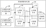
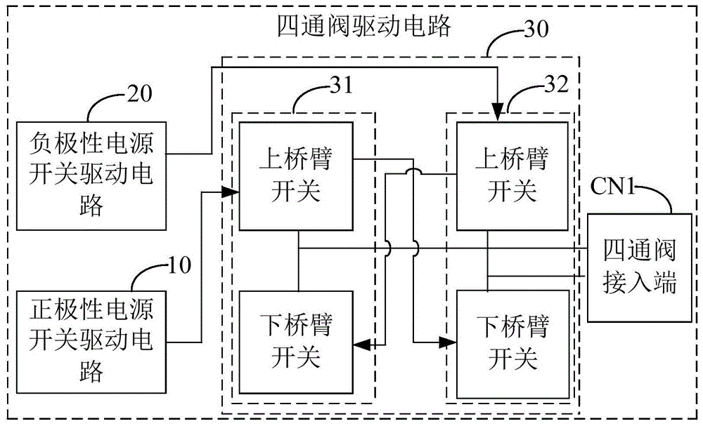
In order to solve the above problem, a novel four-way valve driving circuit is proposed, and referring to fig. 1, in an embodiment of the present invention, the four-way valve driving circuit includes:
a positive polarity power switch drive circuit 10 that operates upon receiving the first control signal M1 and outputs a positive polarity switch drive signal;
a negative polarity power switch drive circuit 20 that operates upon receiving the second control signal M2 and outputs a negative polarity switch drive signal;
the H-bridge switch circuit 30 comprises a first bridge arm circuit 31 and a second bridge arm circuit 32, when receiving the positive polarity switch driving signal, an upper bridge arm switch of the first bridge arm circuit 31 works, and when being conducted, a lower bridge arm switch of the second bridge arm circuit 32 is driven to be conducted, so that the connected positive polarity power supply is output to the direct current four-way valve; and the number of the first and second groups,
when receiving the negative polarity switch driving signal, the upper arm switch of the second arm circuit 32 operates, and when being turned on, the lower arm switch of the first arm circuit 31 is driven to be turned on, so that the accessed negative polarity power supply is output to the direct current four-way valve.
In this embodiment, the four-way valve driving circuit may further include a four-way valve input CN1, the four-way valve input CN1 is equivalent to a power supply electrode input of a four-way valve coil, and is configured to be input to the dc four-way valve, and when a current of the driving power source flows out from one of two terminals of the four-way valve input CN1 to the dc four-way valve, the current flows in from the dc four-way valve from the other terminal. Specifically, two ends of four-way valve inlet CN1 are connected to two ends of the dc four-way valve coil. The common end of the upper arm switch and the lower arm switch in the first arm circuit 31 is connected with one end of a four-way valve access end CN1, and the common end of the upper arm switch and the lower arm switch in the second arm circuit 32 is the other end of the first arm circuit 31 connected with the four-way valve access end CN 1. The upper arm switch of the first arm circuit 31 and the upper arm switch of the second arm circuit 32 are connected to the driving power supply, and the lower arm switch of the first arm circuit 31 and the lower arm switch of the second arm circuit 32 are grounded to the driving power supply, that is, the first arm circuit 31 and the second arm circuit 32 connect the driving power supply and the ground through the four-way valve access end CN1 by the four-way valve coil, so that the accessed driving power supply is output to the four-way valve through the four-way valve access end CN1, and the four-way valve is driven to operate.
In some embodiments, the four-way valve driving circuit is disposed on an electric control board of an outdoor unit of an air conditioner, and the electric control board is further provided with a main control chip for controlling operation of a compressor, a fan, and other devices in the outdoor unit of the air conditioner. Specifically, the main control chip may be a high-level pulse control signal and a low-level pulse control signal, and when receiving the high-level pulse control signal (the first control signal M1), the positive polarity power switch driving circuit 10 outputs a positive polarity switch driving signal; upon receiving the pulse control signal (first control signal M1) at the low level, the positive polarity power switch drive circuit 10 does not operate, that is, does not output the positive polarity switch drive signal. The negative polarity power switch driving circuit 20 outputs a negative polarity switch driving signal when receiving the pulse control signal of high level (the second control signal M2); when receiving the pulse control signal (the second control signal M2) at the low level, the negative polarity switch driving signal is not activated, that is, is not outputted.
It should be noted that, the four-way valve coil includes a first end and a second end, and the positive polarity driving power of the four-way valve means: the current of the drive power supply flows in from the first end a of the four-way valve coil, flows through the four-way valve coil, and then flows out from the second end B of the four-way valve coil. The negative polarity driving power supply of the four-way valve refers to: the current of the drive power supply flows in from the second end B of the four-way valve coil, flows through the four-way valve coil, and then flows out from the first end a of the four-way valve coil.
When the H-bridge switch circuit 30 receives a positive polarity switch driving signal (at this time, the negative polarity power switch driving circuit 20 does not work), the upper bridge arm switch of the first bridge arm circuit 31 is turned on, and drives the lower bridge arm switch of the second bridge arm circuit 32 to be turned on after being turned on, at this time, the upper bridge arm switch of the first bridge arm circuit 31 will be connected with a driving power supply and flow into the first end a of the four-way valve coil through the common end of the first bridge arm circuit 31, and the second end B of the four-way valve coil is grounded through the lower bridge arm switch of the second bridge arm circuit 32, so that the connected positive polarity driving power supply is output to the dc four-way valve. When the H-bridge switch circuit 30 receives a negative polarity switch driving signal (at this time, the positive polarity power switch driving circuit 10 does not work), the upper bridge arm switch of the second bridge arm circuit 32 is turned on, and drives the lower bridge arm switch of the second bridge arm circuit to be turned on after being turned on, at this time, the upper bridge arm switch of the second bridge arm circuit 32 will be connected with a driving power supply and flow into the second end B of the four-way valve coil through the common end of the first bridge arm circuit 31, and the first end a of the four-way valve coil is grounded through the lower bridge arm switch of the first bridge arm circuit 31, so that the connected negative polarity driving power supply is output to the direct current four-way valve. In this embodiment, the positive polarity power switch driving circuit 10 controls the on/off of the upper arm switch of the first arm circuit 31, and then the on/off of the upper arm switch of the first arm circuit 31 controls the on/off of the lower arm switch of the diagonal second arm circuit 32. In this embodiment, the upper arm switch of the second arm circuit 32 is controlled to be turned on/off by the negative polarity power switch driving circuit 20, and the lower arm switch of the second arm circuit 32 at the opposite angle is controlled to be turned on/off by the on/off of the upper arm switch of the second arm circuit 32. By means of the arrangement, when the upper bridge arm switch of the corresponding first bridge arm circuit 31 or second bridge arm circuit 32 is driven to be conducted, the upper bridge arm switch controls the conduction of the lower bridge arm switch on the diagonal direction of the upper bridge arm switch through outputting any one of the positive polarity switch driving signal or the negative polarity switch driving signal, and therefore the four bridge arm switches can be controlled to work through outputting two driving signals.
According to the characteristic that a left end and a right end of a valve core of the four-way valve are arranged, the position of the valve core of the four-way valve is controlled by controlling the direction of a coil of the four-way valve, which is connected with a power electrode, of the four-way valve, when a first end A of the coil of the four-way valve, which is connected with the power electrode, is positive (current of a direct current driving power source flows into the coil from the end), and a second end B of the coil of the four-way valve, which is connected with the power electrode, is negative, the valve core is switched to the left end (or the right end), when the second end B of the coil of the four-way valve, which is connected with the power electrode, is positive (current of the direct current driving power source flows into the coil from the end), and when the first end A is negative, the valve core of the four-way valve is switched to the right end (or the left end), and when the valve core of the four-way valve is positioned at the left end or the right end of a valve body, the valve core of the four-way valve can be kept unchanged at the current position after the power source is switched off. According to the arrangement, the air conditioner enters a refrigeration, dehumidification or heating mode after being started, or the refrigeration, dehumidification mode and the heating mode are switched mutually, the conduction of the lower bridge arm switch on the diagonal line is controlled by controlling the conduction of the upper bridge arm switch of the first bridge arm circuit 31 and the upper bridge arm switch of the second bridge arm circuit 32 in the H-bridge circuit to form the direction of the current of the direct current driving power supply for driving the four-way valve to work to flow through the four-way valve, so that the four-way valve is opened to the corresponding refrigeration, dehumidification or heating mode, then all the bridge arm switches in the H-bridge circuit can be turned off to turn off the direct current driving power supply for the four-way valve, the self-holding of the state of the four-way valve is realized, and the energy-saving purpose is achieved.
The invention is provided with a positive polarity power switch driving circuit 10, works when receiving a first control signal M1, and outputs a positive polarity switch driving signal to control the work of an upper bridge arm switch of a first bridge arm circuit 31 in an H bridge switch circuit 30, and drives a lower bridge arm switch of a second bridge arm circuit 32 to be conducted when the upper bridge arm switch is conducted to output the accessed positive polarity power to a direct current four-way valve, and is also provided with a negative polarity power switch driving circuit 20, works when receiving a second control signal M2, and outputs a negative polarity switch driving signal to control the work of the upper bridge arm switch of the second bridge arm circuit 32 in the H bridge switch circuit 30, and drives the lower bridge arm switch of the first bridge arm circuit 31 to be conducted when the upper bridge arm switch is conducted to output the accessed negative polarity power to the direct current four-way valve. According to the invention, no relay is needed to be arranged, and the H-bridge switch circuit 30, the positive polarity power switch driving circuit 10 and the negative polarity power switch driving circuit 20 output positive polarity switch driving signals or negative polarity switch driving signals, so that when the upper bridge arm switch of the corresponding first bridge arm circuit 31 or second bridge arm circuit 32 in the H-bridge switch circuit 30 is driven to be conducted, the upper bridge arm switch controls the conduction of the lower bridge arm switch on the diagonal angle with the upper bridge arm switch, thereby realizing that the four bridge arm switches can be controlled to work by outputting two driving signals, and further solving the problem that the upper pipe and the lower pipe of the same bridge arm switch are directly connected. In addition, the circuit structure of the four-way valve driving circuit can be simplified, the design requirements on devices can be reduced, and the circuit of the electric control board of the electrical equipment can be simplified, so that the size of the electric control board is reduced, and the installation convenience of the electric control board in the electrical equipment is improved. The invention improves the driving efficiency of the four-way valve, can realize the self-holding of the state of the four-way valve and is beneficial to energy conservation and emission reduction.
It can be understood that the four-way valve driving circuit of the invention has simple circuit structure and easy realization, and can be widely applied to the driving of electrical elements which need to output driving circuits with positive and negative polarities, namely the four-way valve driving circuit of the invention comprises but is not limited to the driving of the four-way valve.
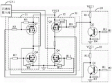
Referring to fig. 1 and 2, in an embodiment, the positive polarity power switch driving circuit 10 includes a first switch Q1, a first resistor R1 and a second resistor R2, a first end of the first resistor R1 is a controlled end of the positive polarity power switch driving circuit 10, and a second end of the first resistor R1 is interconnected with the controlled end of the first switch Q1 and a first end of the second resistor R2; the input end of the first switch Q1 and the second end of the second resistor R2 are both grounded, and the output end of the first switch Q1 is the output end of the positive polarity power switch driving circuit 10.
In this embodiment, the first switch Q1 may be implemented by a transistor, an IGBT, a MOS transistor, or the like, and in this embodiment, the first switch Q1 may be implemented by an NPN transistor, where the NPN transistor is turned on when receiving the first control signal M1 at a high level to output the first switch driving signal to the first switch circuit, and turned off when receiving the first control signal M1 at a low level to stop outputting the first switch driving signal to the first switch circuit. The first resistor R1 and the second resistor R2 form a voltage dividing circuit, and are used for dividing the voltage of the first control signal M1 and outputting the divided voltage to the NPN transistor.
Referring to fig. 1 and 2, in an embodiment, the positive polarity power switch driving circuit 10 further includes a first pull-up resistor R13, a first end of the first pull-up resistor R13 is connected to a first dc power source, and a second end of the first pull-up resistor R13 is connected to the controlled end of the first bridge arm circuit 31.
In this embodiment, it can be understood that the upper arm switch of the first arm circuit 31 is a switching tube, for example, a P-MOS tube, which is turned on at a low level, so that when the positive polarity power switch driving circuit 10 does not operate, that is, when the positive polarity driving signal is not output, the controlled end of the upper arm switch is kept at a high potential voltage by the first pull-up resistor R13, which is different from the high potential voltage, so that the response speed of the upper arm switch to the positive polarity driving signal can be increased, and meanwhile, when the positive polarity power switch driving circuit 10 does not output the positive polarity driving signal, an interference signal on a loop can be prevented from triggering the upper arm switch to be turned on erroneously. Of course, in other embodiments, the upper arm switch of the first arm circuit 31 is a switching tube that can also be turned on at a high level, and at this time, the first pull-up resistor R13 is replaced by a pull-down resistor accordingly.
Referring to fig. 1 and 2, in an embodiment, the negative power switch driving circuit 20 includes a second switch transistor Q2, a third resistor R3, and a fourth resistor R4, a first end of the third resistor R3 is a controlled end of the negative power switch driving circuit 20, and a second end of the third resistor R3 is interconnected with a controlled end of the second switch transistor Q2 and a first end of the fourth resistor R4; the input end of the second switch tube Q2 and the second end of the fourth resistor R4 are both grounded, and the output end of the second switch tube Q2 is the output end of the negative polarity power switch driving circuit 20.
In this embodiment, the second switch Q2 may be implemented by a transistor, an IGBT, a MOS transistor, or the like, and in this embodiment, the first switch Q1 may be implemented by an NPN transistor, where the NPN transistor is turned on when receiving the second control signal M2 at a high level to output the second switch driving signal to the second switch circuit, and turned off when receiving the first control signal M1 at a low level to stop outputting the second switch driving signal to the second switch circuit. The third resistor R3 and the fourth resistor R4 form a voltage dividing circuit, and are used for dividing the voltage of the second control signal M2 and outputting the divided voltage to the NPN transistor.
Referring to fig. 1 and 2, in an embodiment, the negative power switch driving circuit 20 further includes a second pull-up resistor R14, a first end of the second pull-up resistor R14 is connected to the first dc power source, and a second end of the second pull-up resistor R14 is connected to the controlled end of the upper arm switch of the second arm circuit 32.
In this embodiment, it can be understood that the upper arm switch of the second arm circuit 32 is a switching tube, for example, a P-MOS tube, which is turned on at a low level, so that when the positive polarity power switch driving circuit 10 does not operate, that is, when the positive polarity driving signal is not output, the controlled end of the upper arm switch is kept at a high potential voltage by the second pull-up resistor R14, which is different from the high potential voltage, so that the response speed of the upper arm switch to the positive polarity driving signal can be increased, and meanwhile, when the positive polarity power switch driving circuit 10 does not output the positive polarity driving signal, an interference signal on a loop can be prevented from triggering the upper arm switch to be turned on erroneously. Of course, in other embodiments, the upper arm switch of the second arm circuit 32 is a switching tube that can also be turned on at a high level, and at this time, the second pull-up resistor R14 is replaced by a pull-down resistor correspondingly.
Referring to fig. 1 and 2, in an embodiment, the upper leg switch in the first leg circuit 31 includes a third switching tube Q3, a fifth resistor R5 and a sixth resistor R6, a first end of the sixth resistor R6 is connected to the output end of the positive polarity power switch driving circuit 10, and a second end of the sixth resistor R6 is interconnected with a controlled end of the third switching tube Q3 and a first end of the sixth resistor R6; an input end of the third switching tube Q3 is interconnected with a second end of the sixth resistor R6 and a second direct current power supply; and the output end of the third switching tube Q3 is connected with a direct-current four-way valve.
In this embodiment, the third switching tube Q3 may be implemented by a power tube such as an MOS tube or an IGBT, and in this embodiment, the third switching tube Q3 may be implemented by a P-MOS tube, where the P-MOS tube is turned off when receiving a high-level positive polarity switch driving signal and turned on when receiving a low-level positive polarity switch driving signal, so as to provide a driving power supply for the four-way valve, and when turned on, drive the lower arm switch of the second arm circuit 32 to be turned on. The sixth resistor R6 is a current limiting resistor to prevent the MOS transistor from being damaged by an excessive current output to the gate of the MOS transistor, and the sixth resistor R6 is a bias resistor to provide a bias voltage for the MOS transistor.
Referring to fig. 1 and 2, in an embodiment, the lower leg switch in the first leg circuit 31 includes a fourth switch tube Q4, a seventh resistor R7 and an eighth resistor R8, a first end of the seventh resistor R7 is connected to an output end of the upper leg switch of the second leg circuit 32, and a second end of the seventh resistor R7 is interconnected to a controlled end of the fourth switch tube Q4 and a first end of the eighth resistor R8; the input end of the fourth switching tube Q4 is connected with a direct-current four-way valve; the output end of the fourth switching tube Q4 and the second end of the eighth resistor R8 are grounded.
In this embodiment, the fourth switching tube Q4 may be implemented by using a power tube such as an MOS tube or an IGBT, and in this embodiment, the fourth switching tube Q4 may be an N-MOS tube, and is turned on when the upper arm switch of the second upper arm circuit is turned on and outputs a high-level driving signal based on control of the upper arm switch of the second upper arm circuit, so as to provide a ground terminal for the four-way valve, and at this time, the fourth switching tube Q4 forms a current loop with the upper arm switch of the second upper arm circuit and the four-way valve to drive the four-way valve to operate. Fourth switching tube Q4 is kept in the off state when the upper arm switch of the second upper arm circuit is off, so that it can be prevented from being vertically connected to the upper arm switch in first arm circuit 31.
Referring to fig. 1 and 2, in an embodiment, the upper leg switch in the second leg circuit 32 includes a fifth switch transistor Q5, a ninth resistor R9 and a tenth resistor R10, a first end of the ninth resistor R9 is connected to the output end of the positive polarity power switch driving circuit 10, and a second end of the ninth resistor R9 is interconnected to the controlled end of the fifth switch transistor Q5 and a first end of the tenth resistor R10; an input terminal of the fifth switching tube Q5 is interconnected with the second terminal of the tenth resistor R10 and a second dc power supply; and the output end of the fifth switching tube Q5 is connected with a direct-current four-way valve.
In this embodiment, the fifth switching tube Q5 may be implemented by a power tube such as an MOS tube or an IGBT, and in this embodiment, the fifth switching tube Q5 may be a P-MOS tube, and the P-MOS tube is turned off when receiving a high-level positive polarity switch driving signal and turned on when receiving a low-level positive polarity switch driving signal, so as to provide a driving power supply for the four-way valve, and when turned on, drive the lower arm switch of the first arm circuit 31 to be turned on. The ninth resistor R9 is a current limiting resistor to prevent the MOS transistor from being damaged by an excessive current output to the gate of the MOS transistor, and the tenth resistor R10 is a bias resistor to provide a bias voltage for the MOS transistor.
Referring to fig. 1 and 2, in an embodiment, the lower leg switch in the first leg circuit 31 includes a sixth switch tube Q6, an eleventh resistor R11 and a twelfth resistor R12, a first end of the eleventh resistor R11 is connected to the output end of the upper leg switch of the first leg circuit 31, and a second end of the eleventh resistor R11 is interconnected to the controlled end of the sixth switch tube Q6 and a first end of the twelfth resistor R12; the input end of the sixth switching tube Q6 is connected with a direct-current four-way valve; an output terminal of the sixth switching tube Q6 and a second terminal of the twelfth resistor R12 are grounded.
In this embodiment, the sixth switching tube Q6 may be implemented by a power tube such as an MOS tube or an IGBT, and in this embodiment, the sixth switching tube Q6 may be an N-MOS tube, and is turned on when the upper arm switch of the first upper arm circuit is turned on and outputs a high-level driving signal based on control of the upper arm switch of the first upper arm circuit, so as to provide a ground terminal for the four-way valve, and at this time, the sixth switching tube Q6 forms a current loop with the upper arm switch of the first upper arm circuit and the four-way valve, so as to drive the four-way valve to operate.
Referring to fig. 1 and 2, in an embodiment, the four-way valve electric control board further includes a second absorption circuit 50, and the second absorption circuit 60 is connected in parallel to two ends of the ac four-way valve input CN 1.
In this embodiment, the second absorption circuit 50 includes a resistor and a capacitor, the resistor and the capacitor form a resistance-capacitance absorption circuit, and the second absorption circuit 50 is connected to two ends of the coil of the ac four-way valve through two ends of the ac four-way valve connection terminal CN1, and is configured to absorb and consume a self-induced electromotive force generated by an inductive load such as the ac four-way valve when the circuit is disconnected, so as to prevent insulation breakdown of the load due to an overvoltage.
The invention relates to an air conditioner, which comprises a four-way valve and a four-way valve driving circuit, wherein the output end of the four-way valve driving circuit is connected with the power end of the four-way valve; the four-way valve is a direct-current four-way valve. The detailed structure of the four-way valve driving circuit can refer to the above embodiments, and is not described herein; it can be understood that, because the four-way valve driving circuit is used in the air conditioner of the present invention, the embodiment of the air conditioner of the present invention includes all technical solutions of all embodiments of the four-way valve driving circuit, and the achieved technical effects are also completely the same, and are not described herein again.
The above description is only an alternative embodiment of the present invention, and not intended to limit the scope of the present invention, and all modifications and equivalents of the present invention, which are made by the contents of the present specification and the accompanying drawings, or directly/indirectly applied to other related technical fields, are included in the scope of the present invention.