CN110402376B - Torque sensor - Google Patents
Torque sensor Download PDFInfo
- Publication number
- CN110402376B CN110402376B CN201880017928.7A CN201880017928A CN110402376B CN 110402376 B CN110402376 B CN 110402376B CN 201880017928 A CN201880017928 A CN 201880017928A CN 110402376 B CN110402376 B CN 110402376B
- Authority
- CN
- China
- Prior art keywords
- yokes
- magnetic
- shaft
- torque sensor
- yoke
- Prior art date
- Legal status (The legal status is an assumption and is not a legal conclusion. Google has not performed a legal analysis and makes no representation as to the accuracy of the status listed.)
- Active
Links
Images


Classifications
-
- G—PHYSICS
- G01—MEASURING; TESTING
- G01L—MEASURING FORCE, STRESS, TORQUE, WORK, MECHANICAL POWER, MECHANICAL EFFICIENCY, OR FLUID PRESSURE
- G01L3/00—Measuring torque, work, mechanical power, or mechanical efficiency, in general
- G01L3/02—Rotary-transmission dynamometers
- G01L3/04—Rotary-transmission dynamometers wherein the torque-transmitting element comprises a torsionally-flexible shaft
- G01L3/10—Rotary-transmission dynamometers wherein the torque-transmitting element comprises a torsionally-flexible shaft involving electric or magnetic means for indicating
- G01L3/101—Rotary-transmission dynamometers wherein the torque-transmitting element comprises a torsionally-flexible shaft involving electric or magnetic means for indicating involving magnetic or electromagnetic means
- G01L3/104—Rotary-transmission dynamometers wherein the torque-transmitting element comprises a torsionally-flexible shaft involving electric or magnetic means for indicating involving magnetic or electromagnetic means involving permanent magnets
-
- G—PHYSICS
- G01—MEASURING; TESTING
- G01L—MEASURING FORCE, STRESS, TORQUE, WORK, MECHANICAL POWER, MECHANICAL EFFICIENCY, OR FLUID PRESSURE
- G01L3/00—Measuring torque, work, mechanical power, or mechanical efficiency, in general
- G01L3/02—Rotary-transmission dynamometers
- G01L3/04—Rotary-transmission dynamometers wherein the torque-transmitting element comprises a torsionally-flexible shaft
- G01L3/10—Rotary-transmission dynamometers wherein the torque-transmitting element comprises a torsionally-flexible shaft involving electric or magnetic means for indicating
-
- G—PHYSICS
- G01—MEASURING; TESTING
- G01L—MEASURING FORCE, STRESS, TORQUE, WORK, MECHANICAL POWER, MECHANICAL EFFICIENCY, OR FLUID PRESSURE
- G01L5/00—Apparatus for, or methods of, measuring force, work, mechanical power, or torque, specially adapted for specific purposes
- G01L5/22—Apparatus for, or methods of, measuring force, work, mechanical power, or torque, specially adapted for specific purposes for measuring the force applied to control members, e.g. control members of vehicles, triggers
- G01L5/221—Apparatus for, or methods of, measuring force, work, mechanical power, or torque, specially adapted for specific purposes for measuring the force applied to control members, e.g. control members of vehicles, triggers to steering wheels, e.g. for power assisted steering
Abstract
The torque sensor includes: a torsion bar (13) that converts a torque applied between the first shaft (11) and the second shaft (12) into a torsional displacement; a multipolar magnet (20) fixed to one end side of the first shaft or the torsion bar and magnetized with N poles and S poles alternately in the circumferential direction; a plurality of first yokes (21) arranged in the circumferential direction in the radial outer direction of the multipole magnet; a plurality of second yokes (22) which are arranged in the circumferential direction in the radial outer direction of the multipole magnet so as to be sandwiched between the two first yokes; and a magnetism collecting part (25, 35, 40, 45, 50, 55, 60, 65, 70, 75) which has a first body part (261, 361, 411, 461, 511, 561, 611, 711, 761) positioned on a first axial side of the plurality of first yokes in the axial direction and a second body part (271, 721, 771) positioned on a second axial side of the plurality of second yokes in the axial direction and forms a magnetic path in a magnetic field generated by the multipole magnet together with the plurality of first yokes and the plurality of second yokes.
Description
Cross reference to related applications
The present application is based on japanese patent application No. 2017-069923, filed on 31/3/2017, the contents of which are incorporated herein by reference.
Technical Field
The present disclosure relates to a torque sensor.
Background
Conventionally, there has been known a torque sensor including a yoke forming a magnetic path in accordance with a positional relationship with a multipolar magnet provided on a rotating shaft, a magnetic flux collecting portion provided radially outward of the yoke and inducing a magnetic flux, and a magnetic sensor provided in the magnetic flux collecting portion and capable of detecting a magnetic flux density of the magnetic path. In the torque sensor, a shaft torque acting on the rotating shaft is calculated based on a change in magnetic flux density of the magnetic circuit. For example, patent document 1 describes a torque sensor including: a yoke having a plurality of claws located over the entire circumference of the multipole magnet in the radial outward direction and an annular ring-shaped portion connecting the plurality of claws to each other in the radial outward direction; an annular magnetic collecting portion provided so as to surround the yoke in a radial outer direction of the yoke; and a magnetic sensor.
Documents of the prior art
Patent document
Patent document 1: japanese patent No. 3874642 specification
Disclosure of Invention
The torque sensor preferably has a constant detection sensitivity for the torque acting on the rotating shaft. When a part of the magnetic circuit is formed at a position away from the rotation center of the rotating shaft, it is necessary to suppress a change in detection sensitivity caused by a change in position within a predetermined range.
In the torque sensor described in patent document 1, when the relative position of the yoke and the magnetism collecting portion in the axial direction and the radial direction changes, the magnetism collecting portion faces the entire circumference of the yoke, thereby suppressing a change in detection sensitivity. Specifically, the multipolar magnet, the yoke, and the magnetism collecting unit are configured such that the facing areas are kept constant with respect to changes in the relative positions of the multipolar magnet, the yoke, and the magnetism collecting unit in the axial direction. Further, the multipolar magnet, the yoke, and the magnetism collecting portion are changed in position relative to the multipolar magnet, the yoke, and the magnetism collecting portion in the radial direction, and the change in detection sensitivity is suppressed by keeping the total gap of the magnetic circuit constant.
In addition, the torque sensor needs to suppress the influence of leakage magnetic flux from the magnetic circuit within a predetermined range. The leakage flux refers to a noise component in the magnetic flux from the magnet surface that is detected by the magnetic sensor regardless of the twist of the rotation shaft.
In the torque sensor described in patent document 1, the annular ring portion is provided in the yoke, so that the distance from the surface of the multipole magnet to the magnetic sensor is kept constant or longer, thereby suppressing the influence of the leakage magnetic flux.
As described above, in the torque sensor described in patent document 1, in order to suppress the change in detection sensitivity caused by the position change within a predetermined range and suppress the influence of the leakage magnetic flux from the magnetic circuit within a predetermined range, it is necessary to provide the magnetic flux collecting portion facing the entire circumference of the yoke and to provide the yoke with an annular portion. That is, in order to ensure the robustness of the detection sensitivity, the number of raw materials required for forming the magnetic flux collecting portion and the yoke increases, and the manufacturing cost increases.
In the torque sensor described in patent document 1, the yoke and the magnetism collecting portion are both formed in an annular shape. Therefore, for example, when the yoke and the magnetic collecting portion are formed by punching a plate material, the plate material is punched out in an annular shape, so that the amount of excess material increases, and the yield decreases.
An object of the present disclosure is to provide a torque sensor capable of reducing raw materials required for manufacturing and improving yield while ensuring robustness of detection sensitivity against position change.
The torque sensor of the present disclosure includes a torsion bar, a multi-pole magnet, a first yoke, a second yoke, a magnetism collecting unit, and a magnetic sensor.
The torsion bar coaxially connects the first shaft and the second shaft, and converts a torque applied between the first shaft and the second shaft into a torsional displacement.
The multi-pole magnet is fixed to one end side of the first shaft or the torsion bar, and has N poles and S poles alternately magnetized in the circumferential direction.
The plurality of first yokes are fixed to the second shaft or the other end side of the torsion bar, and are arranged at equal intervals in the circumferential direction in the radial outer direction of the multipole magnet.
The plurality of second yokes are fixed to the second shaft or the other end side of the torsion bar together with the plurality of first yokes. The plurality of second yokes are arranged at equal intervals in the circumferential direction so as to be sandwiched between two of the plurality of first yokes in the radial direction of the multi-pole magnet.
The magnetic collecting portion has a first body portion located on a first axial side of the plurality of first yokes in the axial direction and a second body portion located on a second axial side of the plurality of second yokes in the axial direction. The magnetic collecting portion forms a magnetic path in a magnetic field generated by the multi-pole magnet together with the plurality of first yokes and the plurality of second yokes.
The magnetic sensor is provided radially outward of the first and second main bodies and is capable of detecting a magnetic flux density generated in the magnetic circuit.
In the torque sensor of the present disclosure, the magnetism collecting portion is located on the first shaft side of the first yoke and the second shaft side of the second yoke in the axial direction. Thus, when the first shaft and the second shaft are displaced in the radial direction, the facing area of the magnetic flux collecting portion with respect to the first yoke and the second yoke does not change. When the first shaft and the second shaft are displaced in the axial direction, the total amount of gaps between the first yoke and the second yoke and the magnetic collecting portion, that is, the total gap in the magnetic path does not change. Therefore, it is possible to suppress a change in the detection sensitivity of the magnetic sensor when the position in the radial direction or the axial direction changes. That is, robustness of detection sensitivity against a change in position of a member forming the magnetic circuit can be ensured.
In the torque sensor of the present disclosure, the first yoke and the second yoke are provided in plural numbers in the radial direction outside the multipole magnet. Thus, in the torque sensor of the present disclosure, compared to a case where an annular member provided so as to surround the entire circumference of the multipole magnet in the radial outer direction is formed as a yoke, raw materials required for forming the yoke can be reduced.
In addition, for example, when an annular member is punched out of a plate material, the central portion of the annular member is not required, and therefore, a relatively large surplus material is obtained. However, in the torque sensor of the present disclosure, since the plurality of first yokes and the plurality of second yokes can be separately formed, the amount of excess material can be reduced.
In this way, the torque sensor of the present disclosure can reduce raw materials required for manufacturing and improve yield while ensuring robustness of detection sensitivity.
Drawings
The above and other objects, features and advantages of the present disclosure will become more apparent from the following detailed description with reference to the accompanying drawings. The attached drawings are as follows:
fig. 1 is an exploded perspective view of a torque sensor according to a first embodiment.
Fig. 2 is a schematic configuration diagram of an electric power steering apparatus to which a torque sensor according to the first embodiment is applied.
Fig. 3 is a schematic diagram of the torque sensor of the first embodiment.
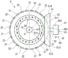
Fig. 4 is a sectional view taken along line IV-IV of fig. 3.
Fig. 5 is a schematic diagram illustrating the area of the plate material required for forming the yoke and the magnetic collecting portion of the torque sensor according to the first embodiment.
Fig. 6 is a characteristic diagram illustrating the effect of the torque sensor according to the first embodiment.
Fig. 7 is a schematic diagram of a torque sensor of the second embodiment.
Fig. 8 is a schematic diagram of a torque sensor of the third embodiment.
Fig. 9 is a schematic diagram of a torque sensor of the fourth embodiment.
Fig. 10 is a schematic diagram of a torque sensor of the fifth embodiment.
Fig. 11 is a schematic diagram of a torque sensor of the sixth embodiment.
Fig. 12 is a schematic diagram of a torque sensor of the seventh embodiment.
Fig. 13 is a schematic diagram of a torque sensor of the eighth embodiment.
Fig. 14 is a schematic diagram of a torque sensor of the ninth embodiment.
Fig. 15 is a sectional view taken along line XV-XV of fig. 14.
Fig. 16 is a schematic diagram of a magnetism collecting unit provided in the torque sensor according to the tenth embodiment.
Fig. 17 is a partial sectional view of a torque sensor of the tenth embodiment.
Fig. 18 is a schematic diagram illustrating a shape of a yoke provided in the torque sensor according to the other embodiment.
Detailed Description
Hereinafter, embodiments of the torque sensor according to the present disclosure will be described with reference to the drawings. In the embodiments, substantially the same components are denoted by the same reference numerals, and description thereof is omitted.
(first embodiment)
As shown in fig. 2, the torque sensor 1 according to the first embodiment is applied to, for example, an Electric power steering (Electric power steering) device for assisting a steering operation of a vehicle. Fig. 2 shows an overall configuration of a steering system including an electric power steering apparatus 90.
The torque sensor 1 is provided on a steering shaft 94 connected to a steering wheel 93. A pinion 96 is provided at the front end of the steering shaft 94. The pinion 96 meshes with the rack shaft 97. A pair of wheels 98 are rotatably coupled to both ends of the rack shaft 97 via Tie rods (Tie rod) or the like. The rotational motion of the steering shaft 94 is converted into linear motion of the rack shaft 97 by the pinion 96, and a pair of wheels 98 are steered.
The torque sensor 1 is provided between an input shaft 11 as a "first shaft" and an output shaft 12 as a "second shaft" that constitute the steering shaft 94. The torque sensor 1 detects a steering torque applied to the steering shaft 94 and outputs the steering torque to the ECU 91. The ECU 91 controls the output of the motor 92 based on the detected steering torque. The steering assist torque generated by the motor 92 is reduced in speed via a reduction gear 95, and is transmitted to the steering shaft 94.
Next, the structure of the torque sensor 1 will be described with reference to fig. 1, 3, and 4.
As shown in fig. 1, the torque sensor 1 includes a torsion bar 13, a multi-pole magnet 20, a plurality of first yokes 21, a plurality of second yokes 22, a set of magnetic collectors 25, and two magnetic sensors 31 and 32.
The torsion bar 13 is a rod-shaped elastic member and is provided between the input shaft 11 and the output shaft 12. One end side of the torsion bar 13 is fixed to the input shaft 11 by a fixing pin 14. The other end side of the torsion bar 13 is fixed to the output shaft 12 by a fixing pin 15. Thereby, the torsion bar 13 connects the input shaft 11 and the output shaft 12 to the rotation shaft O. The torsion bar 13 converts the steering torque applied to the steering shaft 94 into a torsional displacement.
The multipolar magnet 20 is a cylindrical member and is fixed to the input shaft 11. The multipolar magnet 20 has N poles and S poles alternately arranged in the circumferential direction to generate magnetic flux in the radial direction. In the first embodiment, the number of N poles and S poles of the multipole magnet 20 is 12 pairs, that is, 24 poles in total.
The first yoke 21 is a substantially trapezoidal plate material made of a soft magnetic material. The plurality of first yokes 21 are provided at equal intervals over the entire circumference of the multipole magnet 20 in the radial direction outside the end portion of the multipole magnet 20 on the input shaft 11 side. The first yoke 21 is positioned on the output shaft 12 side at a narrow width portion in the circumferential direction of the multi-pole magnet 20. In the first embodiment, 12 first yokes 21 are provided. The first yoke 21 forms a magnetic path in the magnetic field formed by the multi-pole magnet 20.
The second yoke 22 is a substantially trapezoidal plate material made of a soft magnetic material. The plurality of second yokes 22 are provided at equal intervals over the entire circumference of the multipole magnet 20 in the radially outer direction of the end portion of the multipole magnet 20 on the output shaft 12 side. The second yoke 22 is positioned on the input shaft 11 side at a narrow width portion in the circumferential direction of the multi-pole magnet 20. In the first embodiment, 12 second yokes 22 are provided. The second yoke 22 forms a magnetic circuit in the magnetic field formed by the multi-pole magnet 20.
The first yoke 21 and the second yoke 22 are alternately arranged in the circumferential direction. That is, the first yoke 21 or the second yoke 22 is sandwiched by the two second yokes 22 or the two first yokes 21, respectively. At this time, as shown in fig. 3, the first yoke 21 and the second yoke 22 face each other with an air gap therebetween in a direction along the rotation axis O (hereinafter, referred to as "rotation axis direction"). In the first embodiment, the first yoke 21 and the second yoke 22 are integrally formed by resin, not shown, and fixed to the output shaft 12.
The set of magnetism collecting portions 25 has a first magnetism collecting member 26 and a second magnetism collecting member 27 each formed of a soft magnetic material. The magnetic collecting portions 25 are arranged to face each other in a rotation axis direction which is a vertical direction in fig. 1.
The first magnetic flux collecting member 26 includes a first body portion 261, a first connecting portion 262, and a first supporting portion 263.
The first body 261 is positioned on the input shaft 11 side of the plurality of first yokes 21 in the rotation axis direction. The first body portion 261 is formed in a partial annular shape having a cross-sectional shape perpendicular to the rotation axis of the torsion bar 13 with a center angle α 1 of 180 degrees as shown in fig. 4. As shown in fig. 4, the first body 261 is formed to have a radial width larger than the radial widths of the first and second yokes 21 and 22. The first body portion 261 forms a magnetic circuit together with the first yoke 21.
The first connecting portion 262 is provided on the end surface of the first body portion 261 on the first yoke 21 side as shown in fig. 3. The first connecting portion 262 is formed to extend from the first body portion 261 in the radial direction of the multipole magnet 20. The first connecting portion 262 separates the first support portion 263 from the multipole magnet 20, thereby reducing the influence of leakage flux from the multipole magnet 20 at the first support portion 263 and inducing the magnetic flux of the first body 261 to the first support portion 263.
The first support portion 263 is provided at an end portion of the first coupling portion 262 opposite to the side connected to the first body portion 261. The first support portion 263 is formed in a flat plate shape provided substantially perpendicularly to the rotation axis O, and supports the magnetic sensors 31 and 32.
The second magnetism collecting member 27 includes a second body 271, a second coupling portion 272, and a second support portion 273.
The second body 271 is located on the output shaft 12 side of the plurality of second yokes 22 in the rotation axis direction. The cross-sectional shape of the second body 271 perpendicular to the rotation axis of the torsion bar 13 is formed in a partial annular shape having a center angle of 180 degrees, similarly to the first body 261. The second body 271 is formed to have a radial width larger than radial widths of the first and second yokes 21 and 22. The second body portion 271 forms a magnetic circuit together with the second yoke 22.
As shown in fig. 3, the second coupling portion 272 is provided on the end surface of the second body 271 on the second yoke 22 side. The second connecting portion 272 is formed to extend from the second body portion 271 in the radial direction of the multipole magnet 20. Second coupling portion 272 separates second support portion 273 from multipole magnet 20, thereby reducing the influence of leakage magnetic flux from multipole magnet 20 at second support portion 273 and inducing magnetic flux of second body 271 toward second support portion 273.
The second support portion 273 is provided at the end of the second connection portion 272 opposite to the side connected to the second body portion 271. The second support portion 273 is formed in a flat plate shape provided substantially perpendicular to the rotation axis O and supports the magnetic sensors 31 and 32.
The magnetic sensors 31 and 32 are provided between the first support portion 263 and the second support portion 273. In the magnetic sensors 31 and 32, magnetic flux passes between the first support portion 263 and the second support portion 273 in the magnetic path formed by the first yoke 21, the magnetism collecting portion 25, and the second yoke 22. The magnetic sensors 31 and 32 detect the magnetic flux density between the first support portion 263 and the second support portion 273 as the intensity of the magnetic field, and output a signal corresponding to the detected intensity of the magnetic field as an output signal. The output signal is output to the outside via the harnesses 33, 34.
Next, the operation of the torque sensor 1 will be explained.
In the neutral state in which no steering torque is applied between the input shaft 11 and the output shaft 12 and no torsional displacement occurs in the torsion bar 13, as shown in fig. 3 and 4, the boundary between the N pole and the S pole of the multi-pole magnet 20 coincides with the center of the first yoke 21 or the second yoke 22. In the neutral state, since the same number of lines of magnetic force are drawn in and out from the N-pole and S-pole of the multi-pole magnet 20 in each of the first yoke 21 and the second yoke 22, the magnetic flux does not leak into the gap between the first yoke 21 and the second yoke 22, and the magnetic flux density detected by the magnetic sensors 31 and 32 is zero.
When a steering torque is applied between the input shaft 11 and the output shaft 12 and a torsional displacement occurs in the torsion bar 13, the relative positions of the multi-pole magnet 20 fixed to the input shaft 11 and the first and second yokes 21 and 22 fixed to the output shaft 12 change in the circumferential direction.
For example, when the first yoke 21 faces the N pole and the second yoke 22 faces the S pole, magnetic lines of force having the S pole and magnetic lines of force having the N pole increase in the first yoke 21 and the second yoke 22, respectively. Thus, the magnetic flux density passing through the magnetic sensors 31 and 32 is substantially proportional to the amount of torsion displacement of the torsion bar 13, and the polarity changes according to the torsion direction of the torsion bar 13. The magnetic sensors 31 and 32 detect the magnetic flux density, i.e., the intensity of the magnetic field, passing through the magnetic sensors 31 and 32 between the first support portion 263 and the second support portion 273. The torque sensor 1 outputs a voltage corresponding to the strength of the detected magnetic field as an output signal, and detects a steering torque between the input shaft 11 and the output shaft 12.
In the torque sensor 1 according to the first embodiment, the first body 261 of the first magnetism collecting member 26 is provided on the input shaft 11 side of the plurality of first yokes 21 in the rotation axis direction, and the second body 271 of the second magnetism collecting member 27 is provided on the output shaft 12 side of the plurality of second yokes 22 in the rotation axis direction. Accordingly, when the input shaft 11 and the output shaft 12 are offset in the radial direction, the facing areas of the magnetic flux collecting portions 25 with respect to the first yoke 21 and the second yoke 22 do not change. When the input shaft 11 and the output shaft 12 are displaced in the axial direction, the total amount of gaps between the first yoke 21 and the second yoke 22 and the magnetic flux collecting portion 25, that is, the total gap in the magnetic circuit does not change. Therefore, the torque sensor 1 can suppress a change in the detection sensitivity of the magnetic sensors 31 and 32 due to a change in the radial and axial positions. This ensures robustness against a change in the position of the member forming the magnetic circuit.
In the torque sensor 1, a plurality of first yokes 21 and second yokes 22 are provided radially outward of the multipole magnet 20. Thus, in the torque sensor 1, compared to a case where an annular member provided so as to surround the entire circumference of the multipole magnet 20 in the radial direction is molded into a yoke, the raw material required for molding the yoke can be reduced. Further, in the case of punching out an annular member from a plate material, a central portion of the annular member is not necessary, and therefore a relatively large surplus material is obtained, but in the torque sensor 1, since the plurality of first yokes 21 and the plurality of second yokes 22 can be formed separately, the surplus material can be reduced.
Fig. 5 is a schematic diagram showing a comparison of the areas of the workpiece members occupied when the yoke and the magnetic collecting portion of the torque sensor are formed.
Fig. 5 shows positions on the plate-like member 100 when the plate-like member 100 as the workpiece is punched and formed with the 8 first yokes 21, the 8 second yokes 22, the first magnetic flux collecting members 26, and the second magnetic flux collecting members 27 of the torque sensor 1.
Fig. 5 shows, as a comparative example, the area of the plate-like member 100 which is occupied by the yokes 81 and 82 and the magnetic flux collectors 83 and 84 of the torque sensor provided with the annular yokes 81 and 82 and the annular magnetic flux collectors 83 and 84 having 8 claws. In fig. 5, in order to avoid complication of the drawing, the number of yokes of the torque sensor 1 and the number of claws of the torque sensor of the comparative example are 16, respectively.
In the torque sensor of the comparative example, when the yokes 81 and 82 are formed, the plate-like member 100 needs to be punched out in a circular shape in accordance with the size of the yokes 81 and 82 as shown in the two-dot chain line S0, and therefore the area of the plate-like member 100 is relatively large. That is, a relatively large amount of raw material is required for manufacturing the yokes 81 and 82. In addition, the central portions of the yokes 81 and 82 are not used as the yokes 81 and 82, and thus become surplus materials. Therefore, in the torque sensor of the comparative example, a large amount of excess material is generated, and thus the yield is low.
On the other hand, in the torque sensor 1, 8 first yokes 21 and 8 second yokes 22 each having a substantially trapezoidal shape are punched out and formed from the plate-like member 100. At this time, as shown in the two-dot chain line S1 in fig. 5, the punch position can be approached. Thus, as shown in fig. 5, even when the first and second magnetism collecting members 26, 27 are formed in the shape of an arc, the area S1 of the plate-like member 100 required for molding the first yoke 21, the second yoke 22, the first magnetism collecting member 26, and the second magnetism collecting member 27 is smaller than the area S0 of the plate-like member 100 required for molding the yokes 81, 82 and the magnetism collecting portions 83, 84 of the torque sensor of the comparative example.
In this way, the first embodiment can reduce the raw materials required for manufacturing the magnetic path member while ensuring the robustness of the detection sensitivity, and improve the yield.
The one-set flux collecting portion 25 has a first body portion 261 and a second body portion 271 formed in an arc shape having a center angle of 180 degrees. Here, the relationship between the magnitude of the central angle of the magnetism collecting portion and the detection sensitivity of the magnetic sensor will be described with reference to fig. 6.
Fig. 6 shows a change in the detection sensitivity of the magnetic sensor with respect to the magnitude of the central angle of the magnetism collecting portion.
In fig. 6, the first horizontal axis represents the size of the central angle of the magnetism collecting portion. The magnitude of the central angle of the magnetism collecting portion is represented by the central angle {2 × (180- θ) }. Here, the angle θ is an angle at which the main body 251 is not formed when the main body 251 is divided by a center line L25 passing through a point C1 on the rotation axis O and the center of the coupling portion 252, as shown in the schematic view of the magnetic flux collecting portion 25 shown in fig. 6. That is, in the characteristic diagram of fig. 6, when (180- θ) indicated by the second horizontal axis is 180, the magnetic concentrating portion is formed in an annular shape because the central angle of the magnetic concentrating portion is 360 degrees. When (180- θ) indicated by the second horizontal axis is 90, the central angle of the magnetic collecting portion is 180 degrees, and therefore the magnetic collecting portion is formed in a semicircular partial annular shape.
In fig. 6, the vertical axis represents the relative values of the detection sensitivities of the magnetic sensors at respective central angles when the detection sensitivity of the magnetic sensor provided in the annular magnetism collecting unit having a central angle of 360 degrees, that is, 1 is set.
As shown in fig. 6, it is understood that the detection sensitivity of the magnetic sensor is hardly lowered when the central angle of the magnetism collecting portion is 360 degrees to 180 degrees. From this, it is understood that the main body portion at a relatively distant position from the coupling portion hardly contributes to the induction of the magnetic flux to the magnetic sensor.
In the first embodiment, the first body portion 261 and the second body portion 271 of the magnetism collecting portion 25 are formed such that the center angle is 180 degrees at which the detection sensitivity of the magnetic sensor is hardly lowered. This makes it possible to reduce the number of members to be processed required for forming the magnetic flux collecting unit 25, as compared with an annular magnetic flux collecting unit having a central angle of 360 degrees, while maintaining the detection sensitivity of the magnetic sensors 31 and 32. Thus, the yield can be further improved.
In the torque sensor 1, the first and second body portions 261 and 271 are formed so that the radial widths are larger than the radial widths of the first and second yokes 21 and 22 so that the first and second body portions 261 and 271 face the first and second yokes 21 and 22 in the axial direction even if the first and second body portions 261 and 271 are offset in the radial direction. Accordingly, even if the first and second body portions 261 and 271 and the first and second yokes 21 and 22 are displaced in the radial direction, the facing areas do not change, and thus, a change in the detection sensitivity of the magnetic sensors 31 and 32 can be suppressed.
(second embodiment)
A torque sensor according to a second embodiment will be described with reference to fig. 7. In the second embodiment, the shape of the body portion is different from that of the first embodiment.
The torque sensor 2 of the second embodiment includes a torsion bar 13, a multi-pole magnet 20, a plurality of first yokes 21, a plurality of second yokes 22, a set of magnetic collectors 35, and two magnetic sensors 31 and 32.
The set of magnetism collecting portions 35 has a first magnetism collecting member 36 and a second magnetism collecting member, not shown, each formed of a soft magnetic material. The first magnetic collecting member 36 and the second magnetic collecting member of the set of magnetic collecting portions 35 are disposed opposite to each other in the rotation axis direction.
Fig. 7 is a schematic view of the multi-pole magnet 20, the first yoke 21, and the first magnetic collecting member 36 when viewed in the rotation axis direction. The first magnetic flux collecting member 36 includes a first body 361, a first connecting portion 262, and a first supporting portion 263. Here, although the configuration of the first magnetic collecting member 36 is described, the second magnetic collecting member included in the set of magnetic collecting portions 35 has the same shape.
The first body 361 is positioned on the input shaft 11 side of the plurality of first yokes 21 in the rotation axis direction. The first body 361 has a partial annular shape with a central angle α 2 smaller than 180 degrees in a cross-sectional shape perpendicular to the rotation axis O as shown in fig. 7. The first body portion 361 forms a magnetic path together with the first yoke 21.
The first connecting portion 262 is provided on the end surface of the first body 361 on the first yoke 21 side, and is formed to extend from the first body 361 in the radial direction of the multipole magnet 20.
In the torque sensor 2 according to the second embodiment, the main body portion of the set of magnetism collecting portions 35 is formed in a partial annular shape having a central angle smaller than 180 degrees. Thus, the second embodiment achieves the same effects as the first embodiment.
The size of the magnetism collecting portion 35 is smaller than that of the magnetism collecting portion 25 of the first embodiment. This can further reduce the raw material required for manufacturing the plurality of first yokes 21, the plurality of second yokes 22, and the set of magnetism collecting portions 35, and can further improve the yield.
(third embodiment)
A torque sensor according to a third embodiment will be described with reference to fig. 8. In the third embodiment, the shape of the body portion is different from that of the first embodiment.
The torque sensor 3 of the third embodiment includes a torsion bar 13, a multi-pole magnet 20, a plurality of first yokes 21, a plurality of second yokes 22, a set of magnetic collectors 40, and two magnetic sensors 31 and 32.
The set of magnetism collecting portions 40 has a first magnetism collecting member 41 and a second magnetism collecting member, not shown, both formed of a soft magnetic material. The first magnetic collecting member 41 and the second magnetic collecting member of the set of magnetic collecting portions 40 are disposed opposite to each other in the rotation axis direction.
Fig. 8 is a schematic view of the multi-pole magnet 20, the first yoke 21, and the first magnetic flux collecting member 41 when viewed in the rotation axis direction. The first magnetic flux collecting member 41 includes a first body 411, a first connecting portion 262, and a first supporting portion 263. Here, although the configuration of the first magnetic collecting member 41 is described, the second magnetic collecting member included in the set of magnetic collecting portions 40 has the same shape.
The first body 411 is located on the input shaft 11 side of the first yokes 21 in the rotation axis direction. The cross-sectional shape of the first body 411 perpendicular to the rotation axis O is a rectangular shape in which the side of the first body 411 opposite to the side where the first connecting portion 262 is provided is cut out along the outer shape of the outer side of the multipole magnet 20 in the radial direction. The cut-away portion 412 is formed so that the central angle α 3 is 180 degrees. The first body portion 411 forms a magnetic circuit together with the first yoke 21.
The first connecting portion 262 is provided on the end surface of the first body 411 on the first yoke 21 side, and is formed to extend from the first body 411 in the radial outward direction of the multipole magnet 20.
In the torque sensor 3 according to the third embodiment, the sectional shape of the body portion of the set of magnetism collecting portions 40 perpendicular to the rotation axis O is formed in a rectangular shape in which the side of the body portion opposite to the side where the coupling portions are provided is cut out along the outer shape of the outer side in the radial direction of the multipole magnet 20. Thus, the third embodiment provides the same effects as the first embodiment.
(fourth embodiment)
A torque sensor according to a fourth embodiment will be described with reference to fig. 9. In the fourth embodiment, the shape of the body portion is different from that of the first embodiment.
The torque sensor 4 of the fourth embodiment includes a torsion bar 13, a multi-pole magnet 20, a plurality of first yokes 21, a plurality of second yokes 22, a set of magnetic collectors 45, and two magnetic sensors 31 and 32.
The set of magnetism collecting portions 45 has first magnetism collecting members 46 each formed of a soft magnetic material and second magnetism collecting members not shown. The first magnetic collecting member 46 and the second magnetic collecting member of the set of magnetic collecting portions 45 are disposed opposite to each other in the rotation axis direction.
Fig. 9 is a schematic view of the multi-pole magnet 20, the first yoke 21, and the first magnetic flux collecting member 46 when viewed in the rotation axis direction. The first magnetic flux collecting member 46 has a first main body 461, a first connecting portion 262, and a first supporting portion 263. Here, although the configuration of the first magnetic collecting member 46 is described, the second magnetic collecting member included in the set of magnetic collecting portions 45 has the same shape.
The first body 461 is positioned on the input shaft 11 side of the first yokes 21 in the rotation axis direction. The cross-sectional shape of the first body portion 461 perpendicular to the rotation axis O is a shape in which the side of the first body portion 461 opposite to the side where the first connecting portion 262 is provided is cut out along the outer shape of the outer side of the multipole magnet 20 in the radial direction. The cut-away portion 462 is formed with a central angle α 4 of less than 180 degrees. The first body portion 461 forms a magnetic path together with the first yoke 21.
The first connecting portion 262 is provided on the end surface of the first body 461 on the first yoke 21 side, and is formed to extend from the first body 461 in the radial outward direction of the multipole magnet 20.
In the torque sensor 4 according to the fourth embodiment, the sectional shape of the body portion of the set of magnetic collecting portions 45 perpendicular to the rotation axis O is formed in a shape in which the side of the first body portion 461 opposite to the side where the first connecting portion 262 is provided is cut out along the outer shape of the outer side in the radial direction of the multipole magnet 20. Thus, the fourth embodiment provides the same effects as the first embodiment.
The size of the magnetism collecting portion 45 is smaller than the size of the magnetism collecting portion 40 of the third embodiment. This can further reduce the raw materials required for manufacturing the plurality of first yokes 21, the plurality of second yokes 22, and the set of magnetic flux collecting portions 45, and can further improve the yield as compared with the third embodiment.
(fifth embodiment)
A torque sensor according to a fifth embodiment will be described with reference to fig. 10. In the fifth embodiment, the shape of the body is different from that of the first embodiment.
The torque sensor 5 of the fifth embodiment includes a torsion bar 13, a multi-pole magnet 20, a plurality of first yokes 21, a plurality of second yokes 22, a set of magnetism collecting portions 50, and two magnetic sensors 31 and 32.
The set of magnetism collecting portions 50 has a first magnetism collecting member 51 and a second magnetism collecting member, not shown, both formed of a soft magnetic material. The first magnetic collecting member 51 and the second magnetic collecting member of the set of magnetic collecting portions 50 are disposed opposite to each other in the rotation axis direction.
Fig. 10 is a schematic view of the multi-pole magnet 20, the first yoke 21, and the first magnetism collecting member 51 when viewed in the rotation axis direction. The first magnetic flux collecting member 51 includes a first body 511, a first connecting portion 262, and a first supporting portion 263. Here, although the configuration of the first magnetic collecting member 51 is described, the second magnetic collecting member included in the set of magnetic collecting portions 50 has the same shape.
The first body portion 511 is positioned on the input shaft 11 side of the plurality of first yokes 21 in the rotation axis direction. The first body portion 511 has a trapezoidal cross-sectional shape perpendicular to the rotation axis O. Specifically, the planar side surface 512 of the first trunk portion 511 in the radial inner direction of the multipolar magnet 20 is substantially parallel to the planar side surface 513 of the multipolar magnet 20 in the radial outer direction. In the cross-sectional shape perpendicular to the rotation axis O, the length of the side surface 512 is shorter than that of the side surface 513. At this time, a central angle α 5 formed by two side surfaces 514, 515 connecting the side surface 512 and the side surface 513 and a point on the rotation axis O is smaller than 180 degrees. The first body portion 511 forms a magnetic path together with the first yoke 21.
The first connecting portion 262 is provided on the side surface 513 of the first barrel 511, and is formed to extend from the first barrel 511 in the radial direction of the multipole magnet 20.
In the torque sensor 5 according to the fifth embodiment, the main body portion of the set of magnetic collecting portions 50 has a trapezoidal cross-sectional shape perpendicular to the rotation axis O. Thus, the fifth embodiment provides the same effects as the first embodiment.
The magnetic flux collecting unit 50 is formed of a linear portion including the main body. Accordingly, as compared with the case where the curved portion is included, the raw material required for manufacturing the plurality of first yokes 21, the plurality of second yokes 22, and the set of magnetic flux collecting portions 50 can be further reduced, and the yield can be further improved.
(sixth embodiment)
A torque sensor according to a sixth embodiment will be described with reference to fig. 11. In the sixth embodiment, the shape of the body portion is different from that of the first embodiment.
The torque sensor 6 according to the sixth embodiment includes a torsion bar 13, a multi-pole magnet 20, a plurality of first yokes 21, a plurality of second yokes 22, a set of magnetism collecting portions 55, and two magnetic sensors 31 and 32.
The set of magnetism collecting portions 55 has first magnetism collecting members 56 each formed of a soft magnetic material, and second magnetism collecting members, not shown. The first magnetic collecting member 56 and the second magnetic collecting member of the set of magnetic collecting portions 55 are provided opposite to each other in the rotation axis direction.
Fig. 11 is a schematic view of the multi-pole magnet 20, the first yoke 21, and the first magnetic flux collecting member 56 when viewed in the rotation axis direction. The first magnetic flux collecting member 56 includes a first body portion 561 and a first support portion 563. Here, although the configuration of the first magnetic collecting member 56 is described, the second magnetic collecting member included in the set of magnetic collecting portions 55 has the same shape.
The first body 561 is positioned on the input shaft 11 side of the first yokes 21 in the rotation axis direction. The cross-sectional shape of the first body portion 561 perpendicular to the rotation axis O is a substantially triangular shape in which the side of the first body portion 561 opposite to the side where the first support portion 563 is provided is cut away along the outer shape of the outer side of the multipole magnet 20 in the radial direction. The cut-away portion 562 is formed with a center angle α 6 of 180 degrees. The first body portion 561 forms a magnetic path together with the first yoke 21.
The first support portion 563 is provided at an end portion of the first body portion 561 on the opposite side to the multipole magnet 20. The first support portion 563 is formed in a flat plate shape provided substantially perpendicular to the rotation axis O, and supports the magnetic sensors 31 and 32.
In the torque sensor 6 according to the sixth embodiment, the sectional shape of the body portion of the set of magnetism collecting portions 55 perpendicular to the rotation axis O is formed in a triangular shape in which the side of the body portion opposite to the side where the coupling portions are provided is cut out along the outer shape of the outer side in the radial direction of the multipole magnet 20. Thus, the sixth embodiment provides the same effects as the first embodiment.
(seventh embodiment)
A torque sensor according to a seventh embodiment will be described with reference to fig. 12. In the seventh embodiment, the shape of the body portion is different from that of the first embodiment.
The torque sensor 7 of the seventh embodiment includes a torsion bar 13, a multi-pole magnet 20, a plurality of first yokes 21, a plurality of second yokes 22, a set of magnetic collectors 60, and two magnetic sensors 31 and 32.
The set of magnetism collecting portions 60 has first magnetism collecting members 61 each formed of a soft magnetic material and second magnetism collecting members not shown. The first magnetic collecting member 61 and the second magnetic collecting member of the set of magnetic collecting portions 60 are disposed opposite to each other in the rotation axis direction.
Fig. 12 is a schematic view of the multi-pole magnet 20, the first yoke 21, and the first magnetic collecting member 61 when viewed in the rotation axis direction. The first magnetic flux collecting member 61 includes a first body portion 611, a first connecting portion 262, and a first supporting portion 263. Here, although the configuration of the first magnetic collecting member 61 is described, the second magnetic collecting member included in the set of magnetic collecting portions 60 has the same shape.
The first body portion 611 is located on the input shaft 11 side of the plurality of first yokes 21 in the rotation axis direction. The cross-sectional shape of the first body portion 611 perpendicular to the rotation axis O is substantially a pentagonal shape in which the side of the first body portion 611 opposite to the side where the first connecting portion 262 is provided is cut away along the outer shape of the radially outer side of the multipole magnet 20. The cut-away portion 612 is formed with a central angle α 7 of less than 180 degrees. The first body portion 611 forms a magnetic circuit together with the first yoke 21.
The first connecting portion 262 is provided on the end surface of the first body portion 611 on the first yoke 21 side, and is formed to extend from the first body portion 611 in the radial outward direction of the multi-pole magnet 20.
In the torque sensor 7 according to the seventh embodiment, the sectional shape of the main body portion of the set of magnetic collecting portions 60 perpendicular to the rotation axis O is formed into a substantially pentagonal shape in which the side of the main body portion opposite to the side where the support portion is provided is cut out along the outer shape of the outer side of the multipole magnet 20 in the radial direction. Thus, the seventh embodiment achieves the same effects as the first embodiment.
The size of the magnetism collecting portion 60 is smaller than that of the magnetism collecting portion 55 according to the sixth embodiment. This can further reduce the raw materials required for manufacturing the plurality of first yokes 21, the plurality of second yokes 22, and the set of magnetic flux collecting portions 60, and can further improve the yield as compared with the sixth embodiment.
(eighth embodiment)
A torque sensor according to an eighth embodiment will be described with reference to fig. 13. In the eighth embodiment, the shapes of the coupling portion and the support portion are different from those of the first embodiment.
The torque sensor 8 according to the eighth embodiment includes a torsion bar 13, a multi-pole magnet 20, a plurality of first yokes 21, a plurality of second yokes 22, a set of magnetic collectors 65, and two magnetic sensors 31 and 32.
The set of magnetism collecting portions 65 has a first magnetism collecting member 66 and a second magnetism collecting member 67, both of which are formed of a soft magnetic material. As shown in fig. 13, the first magnetic collecting member 66 and the second magnetic collecting member 67 are disposed opposite to each other in the rotation axis direction.
The first magnetic collecting member 66 has a first body portion 261, a first coupling portion 662, and a first support portion 663.
The first coupling portion 662 is provided on an end surface of the first body portion 261 on the first yoke 21 side. The first connecting portion 662 is formed to extend from the first body portion 261 in the radial direction of the multipole magnet 20. The first coupling portion 662 induces magnetic flux of the first body portion 261 to the first support portion 663.
The first support portion 663 is provided at an end portion of the first coupling portion 662 on the side opposite to the side coupled to the first body portion 261. The first support portion 663 is formed in a flat plate shape provided substantially parallel to the rotation axis O, and supports the magnetic sensors 31 and 32.
The second magnetic flux collecting member 67 includes a second body 271, a second coupling 672, and a second support 673.
The second coupling portion 672 is provided on the end surface of the second body 271 on the second yoke 22 side. The second connecting portion 672 is formed to extend from the second body 271 in the radial direction of the multipole magnet 20. The second connecting portion 672 has a length in the radial outer direction of the multipole magnet 20 longer than the length of the first connecting portion 662. The second coupling portion 672 induces the magnetic flux of the second body 271 to the second support portion 673.
The second support portion 673 is provided at an end portion of the second coupling portion 672 on the opposite side to the side connected to the second body 271. The second support portion 673 is formed in a flat plate shape provided substantially parallel to the rotation axis O, and supports the magnetic sensors 31 and 32.
In the torque sensor 8 according to the eighth embodiment, the magnetic sensors 31 and 32 are supported by the first support portion 663 and the second support portion 673 formed in a flat plate shape provided substantially parallel to the rotation axis O, and the magnetic induction surfaces of the magnetic sensors 31 and 32 through which magnetic flux passes are arranged so as to face the radial direction of the multi-pole magnet 20. This can relatively reduce the extent to which the magnetic sensors 31 and 32 protrude in the radial direction. Thus, the eighth embodiment achieves the effects as those of the first embodiment, and reduces the volume of the torque sensor 8.
In the torque sensor 8, a first support portion 663 is provided between the magnetic induction surfaces of the magnetic sensors 31 and 32 and the multipolar magnet 20. This blocks the leakage flux of the multipole magnet 20 by the first support portion 663, and thus a decrease in detection sensitivity due to the leakage flux of the multipole magnet 20 can be suppressed.
(ninth embodiment)
A torque sensor according to a ninth embodiment will be described with reference to fig. 14 and 15. In the ninth embodiment, the shape of the magnetism collecting member is different from that of the first embodiment.
The torque sensor 9 of the ninth embodiment includes a torsion bar 13, a multi-pole magnet 20, a plurality of first yokes 21, a plurality of second yokes 22, a set of magnetism collecting portions 70, and two magnetic sensors 31 and 32.
The set of magnetism collecting portions 70 has a first magnetism collecting member 71 and a second magnetism collecting member 72 each formed of a soft magnetic material. As shown in fig. 15, the first magnetic collecting member 71 and the second magnetic collecting member 72 are provided to face each other in the rotation axis direction.
The first magnetic flux collecting member 71 includes a first main body 711, a first connecting portion 712, and a first supporting portion 263.
As shown in fig. 15, the first body 711 is located between the plurality of first yokes 21 and the multi-pole magnet 20, on the input shaft 11 side of the plurality of first yokes 21 in the rotation axis direction, and radially outward of the plurality of first yokes 21 when viewed from the multi-pole magnet 20. That is, the first body 711 is formed to surround the end of the first yoke 21 on the input shaft 11 side. The first body 711 has a partial annular shape with a central angle α 9 smaller than 180 degrees in a cross-sectional shape perpendicular to the rotation axis O as shown in fig. 14. The first body portion 261 forms a magnetic circuit together with the first yoke 21.
The first connecting portion 712 is provided at an end portion of the first body 711 located radially outward of the first yoke 21 when viewed from the multi-pole magnet 20. The first connecting portion 712 is formed to extend from the first trunk portion 711 in the radial direction outside the multipole magnet 20. The first connecting portion 712 induces magnetic flux of the first body portion 711 to the first supporting portion 263.
The first support portion 263 is provided at an end portion of the first coupling portion 712 on the side opposite to the side coupled to the first body portion 711.
The second magnetism collecting member 72 includes a second body 721, a second coupling portion 722, and a second support portion 273.
As shown in fig. 15, the second body portion 721 is located between the plurality of second yokes 22 and the multi-pole magnet 20, on the output shaft 12 side of the plurality of second yokes 22 in the rotation axis direction, and radially outward of the plurality of second yokes 22 when viewed from the multi-pole magnet 20. That is, the second body portion 721 is formed so as to surround the end portion of the second yoke 22 on the output shaft 12 side. The second body portion 721 has a sectional shape perpendicular to the rotation axis O, and is formed in a partial annular shape of less than 180 degrees, like the first body portion 261. The second body portion 721 forms a magnetic circuit together with the second yoke 22.
The second connection portion 722 is provided at an end portion of the second body portion 721 located radially outward of the second yoke 22 as viewed from the multi-pole magnet 20. The second connection portion 722 is formed to extend from the second body portion 721 in the radial direction of the multipole magnet 20. The second connection portion 722 induces a magnetic flux of the second body portion 721 toward the second support portion 273.
The second support portion 273 is provided at an end of the second connection portion 722 opposite to the side connected to the second body portion 721.
In the torque sensor 9 of the ninth embodiment, the main body portions of the set of magnetism collecting portions 70 are positioned not only in the axial direction of the first yoke or the second yoke but also between the yoke and the multi-pole magnet 20 and in the radial direction of the yoke when viewed from the multi-pole magnet 20. This makes it possible to increase the magnetic flux density induced to the support portion because the area of the body portion facing the yoke is relatively large. Therefore, the ninth embodiment can achieve the effects similar to those of the first embodiment, and can improve the detection sensitivity of the magnetic sensors 31 and 32.
Further, since the detection sensitivity of the magnetic sensors 31 and 32 can be improved, the body of the magnetism collecting unit 70 can be shortened in the circumferential direction of the multipole magnet 20 while suppressing a decrease in the detection sensitivity. This can further reduce the raw material required for molding the set of magnetism collecting parts 70.
(tenth embodiment)
A torque sensor according to a tenth embodiment will be described with reference to fig. 16 and 17. In the tenth embodiment, the shape of the magnetic collecting member is different from that of the ninth embodiment.
The torque sensor 10 of the tenth embodiment includes a torsion bar 13, a multi-pole magnet 20, a plurality of first yokes 21, a plurality of second yokes 22, a set of magnetic collectors 75, and two magnetic sensors 31 and 32.
The set of magnetism collecting portions 75 has a first magnetism collecting member 76 and a second magnetism collecting member 77 each formed of a soft magnetic material. As shown in fig. 17, the first magnetic flux collecting member 76 and the second magnetic flux collecting member 77 are provided to face each other in the rotation axis direction.
The first magnetic collecting member 76 includes a first main body portion 761, a first connecting portion 712, and a first supporting portion 263.
The first body portion 761 is located between the plurality of first yokes 21 and the multi-pole magnet 20, on the input shaft 11 side of the plurality of first yokes 21 in the rotation axis direction, and radially outward of the plurality of first yokes 21 when viewed from the multi-pole magnet 20. The first body portion 761 is formed in a partial annular shape having a center angle α 10 of 180 degrees in a cross-sectional shape perpendicular to the rotation axis O as shown in fig. 16. The first body portion 761 forms a magnetic circuit together with the first yoke 21.
The first connecting portion 712 is provided on the opposite side of the first body portion 761 from the multi-pole magnet 20. The first connecting portion 712 is formed to extend from the first body portion 761 in the radial direction of the multipole magnet 20.
The first body portion 761 has an annular portion 762 serving as a "base portion" connected to the first connecting portion 712, and a plurality of bent portions 763. When the first body portion 761 is punched out from the plate-like member by a punch or the like, as shown in fig. 16, a semicircular partial ring shape having a radial length longer than that of the ring portion 762 is formed.
The annular portion 762 is located on the input shaft 11 side of the plurality of first yokes 21 in the rotation axis direction.
The plurality of bent portions 763 are provided radially inward of the annular portion 762. The bent portion 763 is a portion obtained by cutting an annular portion provided on the radially inner side of the annular portion 762 into a plurality of pieces in the radial direction of the annular portion 762. When the first magnetic flux collecting member 76 is provided on the input shaft 11 side of the first yoke 21, the bent portion 763 is bent alternately at the connection line L76 with the annular portion 762. As shown in fig. 17, the bent portions 763 that are bent alternately are alternately located between the plurality of first yokes 21 and the multi-pole magnet 20 or radially outward of the plurality of first yokes 21 when viewed from the multi-pole magnet 20.
The second magnetic flux collecting member 77 includes a second body 771, a second coupling portion 722, and a second support portion 273.
The second body 771 is located between the plurality of second yokes 22 and the multi-pole magnet 20, on the output shaft 12 side of the plurality of second yokes 22 in the rotation axis direction, and radially outward of the plurality of second yokes 22 when viewed from the multi-pole magnet 20. The second body 771 has a sectional shape perpendicular to the rotation axis O and is formed in a partial annular shape having a central angle of 180 degrees, similarly to the first body 761. The second body 771 forms a magnetic path together with the second yoke 22.
The second connection portion 722 is provided on the opposite side of the second body 771 from the multi-pole magnet 20. The second connection portion 722 is formed to extend from the second body 771 in the radial direction of the multipole magnet 20.
The second body 771 includes an annular portion 772 as a "base" connected to the second connection portion 722 and a plurality of bent portions 773. When the second body 771 is punched out of the plate-like member by a punch or the like, the second body 771 is formed into a partial annular shape having a radial length longer than that of the annular portion 772, similarly to the first body 761.
The circular ring portion 772 is located on the output shaft 12 side of the plurality of second yokes 22 in the rotation axis direction.
The plurality of bent portions 773 are formed by cutting a plurality of annular portions provided radially inward of the annular portion 772 in the radial direction of the annular portion 772. When the second magnetic flux collecting member 77 is provided on the output shaft 12 side of the second yoke 22, the bent portions 773 are alternately bent at the connecting positions with the annular portions 772. As shown in fig. 17, the bent portions 773 that are bent alternately are alternately positioned between the plurality of second yokes 22 and the multi-pole magnet 20 or radially outward of the plurality of second yokes 22 when viewed from the multi-pole magnet 20.
In the torque sensor 10 according to the tenth embodiment, the main body portion of the set of magnetism collecting portions 75 is shaped like a flat plate having an annular portion connected to the connecting portion and a plurality of bent portions when punched out from a plate-like member by a punch or the like. This makes it possible to relatively increase the facing area of the body portion with respect to the yoke by a relatively easy molding method. Therefore, the tenth embodiment achieves the effects of the ninth embodiment, and can reduce the manufacturing cost of the torque sensor 10.
(other embodiments)
In the above-described embodiment, the main body portion of the magnetic flux collecting portion is formed in a shape having a central angle of 180 degrees or less. However, the shape of the body portion is not limited thereto. Or may be formed in a ring shape having a center angle of 360 degrees. The shape of the body portion is not limited to a partial annular shape, a substantially rectangular shape, a substantially triangular shape, or a trapezoidal shape.
In the eighth embodiment, the magnetic induction surface of the magnetic sensor is arranged to face the radial direction of the multipole magnet. However, the orientation of the magnetic induction surface is not limited thereto. Or may be in a different direction from the axis of rotation.
In the ninth and tenth embodiments, the body portion of the magnetic flux collecting member is located between the yoke and the multi-pole magnet, on the side of the yoke in the rotation axis direction, and radially outward of the yoke when viewed from the multi-pole magnet. However, the position of the main body of the magnetism collecting member is not limited thereto. The magnetic flux path may be formed between the yoke and the multi-pole magnet and on the side of the yoke in the rotation axis direction, or may be formed radially outward of the yoke when viewed from the multi-pole magnet and on the side of the yoke in the rotation axis direction.
In the above-described embodiment, the first yoke and the second yoke are plate materials having a substantially trapezoidal shape. However, the shapes of the first yoke and the second yoke are not limited to this. The shape may be rectangular, triangular, or a curved shape.
The first yoke is provided radially outward of the end portion of the multipole magnet on the input shaft side, and the second yoke is provided radially outward of the end portion of the multipole magnet on the output shaft side. However, the positions where the first and second yokes are provided are not limited to these. A magnetic path may be formed between the first yoke and the first magnetic collecting member, and a magnetic path may be formed between the second yoke and the second magnetic collecting member.
In the above-described embodiment, the plurality of first yokes and the plurality of second yokes are formed by punching out the plate-like members individually. However, the method of forming the plurality of first yokes and the plurality of second yokes is not limited thereto. For example, as shown in fig. 18, a member coupled by a coupling portion 211 that couples a plurality of first yokes 21 and has a relatively narrow width may be punched out of a flat plate-like member. The same applies to the connection portion 221 that connects the plurality of second yokes 22 and has a relatively narrow width. This allows the plurality of yokes to be easily handled.
The method of forming the plurality of first yokes and the plurality of second yokes is not limited to the method of punching out the flat plate-like member. For example, a plurality of substantially trapezoidal flat plates having a relatively small thickness may be formed by cutting a bar having a substantially trapezoidal cross section.
The present disclosure is not limited to the above embodiment, and can be implemented in various ways within a scope not departing from the gist of the disclosure.
The disclosure has been described in accordance with the embodiments. However, the present disclosure is not limited to the embodiment and the structure. The present disclosure also includes various modifications and equivalent arrangements. In addition, various combinations and modes, and further, other combinations and modes including only one element, more than one element, or less than one element among them also fall within the scope and spirit of the present disclosure.
Claims (8)
1. A torque sensor is characterized by comprising:
a torsion bar (13) that coaxially connects a first shaft (11) and a second shaft (12) and converts a torque applied between the first shaft and the second shaft into a torsional displacement;
a multipolar magnet (20) fixed to one end side of the first shaft or the torsion bar, and having N poles and S poles alternately magnetized in a circumferential direction;
a plurality of first yokes (21) fixed to the second shaft or the other end side of the torsion bar and arranged at equal intervals in the circumferential direction in the radial outer direction of the multipole magnet;
a plurality of second yokes (22) fixed to the second shaft or the other end side of the torsion bar together with the plurality of first yokes, and arranged at equal intervals in the circumferential direction so as to be sandwiched between two of the plurality of first yokes in the radial direction of the multipole magnet;
a magnetic collecting part (25, 35, 40, 45, 50, 55, 60, 65, 70, 75) having a first body part (261, 361, 411, 461, 511, 561, 611, 711, 761) located on the first axial side of the plurality of first yokes in the axial direction and a second body part (271, 721, 771) located on the second axial side of the plurality of second yokes in the axial direction, and the plurality of first yokes and the plurality of second yokes together forming a magnetic path in a magnetic field generated by the multipole magnet; and
magnetic sensors (31, 32) provided on the radially outer sides of the first and second main bodies and capable of detecting the magnetic flux density generated in the magnetic path,
the first and second body portions are formed to have a radial width larger than radial widths of the plurality of first yokes and the plurality of second yokes.
2. The torque sensor according to claim 1,
at least one of the first body and the second body has a partial annular shape in a cross-sectional shape perpendicular to the rotation axes of the first shaft and the second shaft.
3. The torque sensor according to claim 1,
a cross-sectional shape of at least one of the first body portion and the second body portion, which is perpendicular to the rotation axes of the first shaft and the second shaft, is a rectangular shape in which a portion is cut out along an outer shape of the multipole magnet on a radial outer side.
4. The torque sensor according to claim 1,
a cross-sectional shape of at least one of the first body and the second body, which is perpendicular to the rotation axes of the first shaft and the second shaft, is a triangular shape in which a portion of an outer shape of the multipole magnet on the outer side in the radial direction is cut off.
5. The torque sensor according to any one of claims 2 to 4,
at least one of the first body and the second body has a center angle of less than 180 degrees with respect to a point on the rotation axis of the first shaft and the second shaft.
6. The torque sensor according to any one of claims 1 to 4,
the magnetic collecting part has a first support part (663) which is arranged on the radial outer side of the first main body part and supports the magnetic sensor, and a second support part (673) which is arranged on the radial outer side of the second main body part and supports the magnetic sensor in the radial outer direction of the first support part,
the magnetic sensor is provided between the first support portion and the second support portion, and is formed such that a magnetic induction surface through which magnetic flux of the magnetic circuit passes is directed in a radial direction of the multipole magnet.
7. The torque sensor according to any one of claims 1 to 4,
the magnetic circuit further comprises a connecting part (211, 221) for connecting at least one of the plurality of first yokes and the plurality of second yokes.
8. The torque sensor according to claim 1,
at least one of the first body and the second body includes: a base (762, 772) positioned at the first axial side of the plurality of first yokes in the axial direction or at the second axial side of the plurality of second yokes in the axial direction; and a bent portion (763, 773) formed in the base portion and provided so as to be capable of being bent with respect to the base portion.
Applications Claiming Priority (3)
| Application Number | Priority Date | Filing Date | Title |
|---|---|---|---|
| JP2017-069923 | 2017-03-31 | ||
| JP2017069923A JP6687560B2 (en) | 2017-03-31 | 2017-03-31 | Torque sensor |
| PCT/JP2018/010167 WO2018180533A1 (en) | 2017-03-31 | 2018-03-15 | Torque sensor |
Publications (2)
| Publication Number | Publication Date |
|---|---|
| CN110402376A CN110402376A (en) | 2019-11-01 |
| CN110402376B true CN110402376B (en) | 2021-02-23 |
Family
ID=63675917
Family Applications (1)
| Application Number | Title | Priority Date | Filing Date |
|---|---|---|---|
| CN201880017928.7A Active CN110402376B (en) | 2017-03-31 | 2018-03-15 | Torque sensor |
Country Status (4)
| Country | Link |
|---|---|
| US (1) | US11092502B2 (en) |
| JP (1) | JP6687560B2 (en) |
| CN (1) | CN110402376B (en) |
| WO (1) | WO2018180533A1 (en) |
Families Citing this family (2)
| Publication number | Priority date | Publication date | Assignee | Title |
|---|---|---|---|---|
| WO2021107124A1 (en) * | 2019-11-29 | 2021-06-03 | 株式会社デンソー | Yoke member for torque detection device, torque detection device, and steering device |
| EP3875933A1 (en) * | 2020-03-06 | 2021-09-08 | Bourns, Inc. | Torque sensor unit and torque and angle sensor comprising the same |
Citations (14)
| Publication number | Priority date | Publication date | Assignee | Title |
|---|---|---|---|---|
| JPH01127927A (en) * | 1987-11-12 | 1989-05-19 | Toshiba Corp | Torque detector |
| US6810336B2 (en) * | 2002-06-20 | 2004-10-26 | Denso Corporation | Torque sensor having a magnet and a magnetic sensor |
| CN101002078A (en) * | 2004-07-09 | 2007-07-18 | 移动磁体技术公司 | Position sensor which is intended, in particular, for measuring steering column torsion |
| JP2008076149A (en) * | 2006-09-20 | 2008-04-03 | Nsk Ltd | Torsional torque measuring apparatus |
| WO2008105541A1 (en) * | 2007-03-01 | 2008-09-04 | Nsk Ltd. | Torque sensor, electric power steering device, method of producing claw pole, and method of producing torque sensor |
| CN101943619A (en) * | 2009-07-03 | 2011-01-12 | 萱场工业株式会社 | Torque sensor |
| CN102401710A (en) * | 2010-09-13 | 2012-04-04 | 株式会社捷太格特 | Torque and index detection apparatus |
| CN103162886A (en) * | 2011-12-16 | 2013-06-19 | 株式会社电装 | Torque sensor apparatus |
| CN103471498A (en) * | 2013-09-27 | 2013-12-25 | 太仓康茂电子有限公司 | Torque sensor |
| CN103822740A (en) * | 2012-11-15 | 2014-05-28 | 株式会社电装 | Torque sensor |
| CN104169700A (en) * | 2011-12-26 | 2014-11-26 | 株式会社捷太格特 | Yoke unit, yoke unit manufacturing method, torque detection device, and electric power steering device |
| CN105651435A (en) * | 2014-11-27 | 2016-06-08 | 株式会社电装 | Magnetic detection device and torque sensor including the same |
| JP2016161344A (en) * | 2015-02-27 | 2016-09-05 | 株式会社ジェイテクト | Torque detection device |
| CN105987779A (en) * | 2015-03-19 | 2016-10-05 | 本田技研工业株式会社 | Magnetostrictive torque sensor and electric power steering apparatus |
Family Cites Families (11)
| Publication number | Priority date | Publication date | Assignee | Title |
|---|---|---|---|---|
| JP3874642B2 (en) | 2001-05-18 | 2007-01-31 | 株式会社デンソー | Torque sensor and electric power steering apparatus provided with the torque sensor |
| US6644134B2 (en) * | 2002-02-21 | 2003-11-11 | Visteon Global Technologies, Inc. | Flux brush torque sensor |
| DE10316124A1 (en) * | 2003-04-04 | 2004-10-28 | Valeo Schalter Und Sensoren Gmbh | Device for determining a torque exerted on a shaft |
| JP2007187481A (en) * | 2006-01-11 | 2007-07-26 | Jtekt Corp | Torque detector |
| DE102007057050A1 (en) * | 2007-01-29 | 2008-07-31 | Continental Teves Ag & Co. Ohg | Sensor arrangement i.e. torque sensor, for use in steering system of motor vehicle, has additional stator with two stator elements and arranged on shaft section, where stator is directly or indirectly assigned to magnetic encoder |
| KR101633127B1 (en) | 2010-03-30 | 2016-06-24 | 엘지이노텍 주식회사 | Apparatus for detecting torque |
| DE102012104076A1 (en) * | 2011-05-13 | 2012-11-15 | Denso Corp. | torque sensor |
| JP2012237728A (en) * | 2011-05-13 | 2012-12-06 | Denso Corp | Torque sensor |
| JP2013195108A (en) * | 2012-03-16 | 2013-09-30 | Alps Electric Co Ltd | Angle detector,torque detector using angle detector |
| JP5675700B2 (en) * | 2012-05-25 | 2015-02-25 | 株式会社日本自動車部品総合研究所 | Torque sensor |
| JP6007828B2 (en) | 2013-02-27 | 2016-10-12 | 三菱化学株式会社 | Method for producing (meth) acrylic acids |
-
2017
- 2017-03-31 JP JP2017069923A patent/JP6687560B2/en active Active
-
2018
- 2018-03-15 WO PCT/JP2018/010167 patent/WO2018180533A1/en active Application Filing
- 2018-03-15 CN CN201880017928.7A patent/CN110402376B/en active Active
-
2019
- 2019-06-04 US US16/430,479 patent/US11092502B2/en active Active
Patent Citations (14)
| Publication number | Priority date | Publication date | Assignee | Title |
|---|---|---|---|---|
| JPH01127927A (en) * | 1987-11-12 | 1989-05-19 | Toshiba Corp | Torque detector |
| US6810336B2 (en) * | 2002-06-20 | 2004-10-26 | Denso Corporation | Torque sensor having a magnet and a magnetic sensor |
| CN101002078A (en) * | 2004-07-09 | 2007-07-18 | 移动磁体技术公司 | Position sensor which is intended, in particular, for measuring steering column torsion |
| JP2008076149A (en) * | 2006-09-20 | 2008-04-03 | Nsk Ltd | Torsional torque measuring apparatus |
| WO2008105541A1 (en) * | 2007-03-01 | 2008-09-04 | Nsk Ltd. | Torque sensor, electric power steering device, method of producing claw pole, and method of producing torque sensor |
| CN101943619A (en) * | 2009-07-03 | 2011-01-12 | 萱场工业株式会社 | Torque sensor |
| CN102401710A (en) * | 2010-09-13 | 2012-04-04 | 株式会社捷太格特 | Torque and index detection apparatus |
| CN103162886A (en) * | 2011-12-16 | 2013-06-19 | 株式会社电装 | Torque sensor apparatus |
| CN104169700A (en) * | 2011-12-26 | 2014-11-26 | 株式会社捷太格特 | Yoke unit, yoke unit manufacturing method, torque detection device, and electric power steering device |
| CN103822740A (en) * | 2012-11-15 | 2014-05-28 | 株式会社电装 | Torque sensor |
| CN103471498A (en) * | 2013-09-27 | 2013-12-25 | 太仓康茂电子有限公司 | Torque sensor |
| CN105651435A (en) * | 2014-11-27 | 2016-06-08 | 株式会社电装 | Magnetic detection device and torque sensor including the same |
| JP2016161344A (en) * | 2015-02-27 | 2016-09-05 | 株式会社ジェイテクト | Torque detection device |
| CN105987779A (en) * | 2015-03-19 | 2016-10-05 | 本田技研工业株式会社 | Magnetostrictive torque sensor and electric power steering apparatus |
Also Published As
| Publication number | Publication date |
|---|---|
| JP2018173294A (en) | 2018-11-08 |
| WO2018180533A1 (en) | 2018-10-04 |
| US20190285490A1 (en) | 2019-09-19 |
| CN110402376A (en) | 2019-11-01 |
| JP6687560B2 (en) | 2020-04-22 |
| US11092502B2 (en) | 2021-08-17 |
Similar Documents
| Publication | Publication Date | Title |
|---|---|---|
| JP6311926B2 (en) | Torque sensor and electric power steering device | |
| US9121784B2 (en) | Torque detector and electric power steering system including the torque detector | |
| US8800388B2 (en) | Torque sensor apparatus | |
| US20120285266A1 (en) | Torque sensor | |
| JP6670230B2 (en) | Torque detector | |
| JP2004125627A (en) | Torque sensor | |
| EP2868551B1 (en) | On-vehicle detector | |
| CN110402376B (en) | Torque sensor | |
| WO2018024126A1 (en) | Contactless torque sensor | |
| US10132702B2 (en) | Torque detecting device | |
| CN108627292B (en) | Torque sensor | |
| JP2006064577A (en) | Torque detection apparatus | |
| US11099087B2 (en) | Torque detecting device | |
| JP6691071B2 (en) | Torque sensor | |
| JP2011209143A (en) | Torque sensor | |
| JP2011089890A (en) | Torque detector | |
| JP2019120671A (en) | Torque sensor | |
| JP2009020064A (en) | Torque sensor and electric power steering device | |
| JP2009128181A (en) | Torque detector, electric power steering device, and method of producing claw pole | |
| JP2009092463A (en) | Torque detection apparatus, its manufacturing method, and electric power steering system | |
| JP2016090492A (en) | Torque detection device | |
| JP2006052969A (en) | Torque sensor of steering device | |
| JP5814443B2 (en) | Torque sensor | |
| JP2021012165A (en) | Sensor | |
| JP2016095281A (en) | Detection device for vehicle |
Legal Events
| Date | Code | Title | Description |
|---|---|---|---|
| PB01 | Publication | ||
| PB01 | Publication | ||
| SE01 | Entry into force of request for substantive examination | ||
| SE01 | Entry into force of request for substantive examination | ||
| GR01 | Patent grant | ||
| GR01 | Patent grant |