CN110392995B - Method and apparatus for transmitting and receiving radio signal in wireless communication system - Google Patents
Method and apparatus for transmitting and receiving radio signal in wireless communication system Download PDFInfo
- Publication number
- CN110392995B CN110392995B CN201880016978.3A CN201880016978A CN110392995B CN 110392995 B CN110392995 B CN 110392995B CN 201880016978 A CN201880016978 A CN 201880016978A CN 110392995 B CN110392995 B CN 110392995B
- Authority
- CN
- China
- Prior art keywords
- cbg
- cbgs
- harq
- reception
- cbs
- Prior art date
- Legal status (The legal status is an assumption and is not a legal conclusion. Google has not performed a legal analysis and makes no representation as to the accuracy of the status listed.)
- Active
Links
Images


Classifications
-
- H—ELECTRICITY
- H04—ELECTRIC COMMUNICATION TECHNIQUE
- H04L—TRANSMISSION OF DIGITAL INFORMATION, e.g. TELEGRAPHIC COMMUNICATION
- H04L1/00—Arrangements for detecting or preventing errors in the information received
- H04L1/12—Arrangements for detecting or preventing errors in the information received by using return channel
- H04L1/16—Arrangements for detecting or preventing errors in the information received by using return channel in which the return channel carries supervisory signals, e.g. repetition request signals
- H04L1/18—Automatic repetition systems, e.g. Van Duuren systems
- H04L1/1829—Arrangements specially adapted for the receiver end
- H04L1/1861—Physical mapping arrangements
-
- H—ELECTRICITY
- H04—ELECTRIC COMMUNICATION TECHNIQUE
- H04L—TRANSMISSION OF DIGITAL INFORMATION, e.g. TELEGRAPHIC COMMUNICATION
- H04L5/00—Arrangements affording multiple use of the transmission path
- H04L5/003—Arrangements for allocating sub-channels of the transmission path
- H04L5/0053—Allocation of signaling, i.e. of overhead other than pilot signals
- H04L5/0055—Physical resource allocation for ACK/NACK
-
- H—ELECTRICITY
- H04—ELECTRIC COMMUNICATION TECHNIQUE
- H04L—TRANSMISSION OF DIGITAL INFORMATION, e.g. TELEGRAPHIC COMMUNICATION
- H04L1/00—Arrangements for detecting or preventing errors in the information received
- H04L1/12—Arrangements for detecting or preventing errors in the information received by using return channel
- H04L1/16—Arrangements for detecting or preventing errors in the information received by using return channel in which the return channel carries supervisory signals, e.g. repetition request signals
- H04L1/18—Automatic repetition systems, e.g. Van Duuren systems
-
- H—ELECTRICITY
- H04—ELECTRIC COMMUNICATION TECHNIQUE
- H04L—TRANSMISSION OF DIGITAL INFORMATION, e.g. TELEGRAPHIC COMMUNICATION
- H04L1/00—Arrangements for detecting or preventing errors in the information received
- H04L1/004—Arrangements for detecting or preventing errors in the information received by using forward error control
- H04L1/0056—Systems characterized by the type of code used
- H04L1/0061—Error detection codes
-
- H—ELECTRICITY
- H04—ELECTRIC COMMUNICATION TECHNIQUE
- H04L—TRANSMISSION OF DIGITAL INFORMATION, e.g. TELEGRAPHIC COMMUNICATION
- H04L1/00—Arrangements for detecting or preventing errors in the information received
- H04L1/12—Arrangements for detecting or preventing errors in the information received by using return channel
- H04L1/16—Arrangements for detecting or preventing errors in the information received by using return channel in which the return channel carries supervisory signals, e.g. repetition request signals
- H04L1/1607—Details of the supervisory signal
- H04L1/1614—Details of the supervisory signal using bitmaps
-
- H—ELECTRICITY
- H04—ELECTRIC COMMUNICATION TECHNIQUE
- H04L—TRANSMISSION OF DIGITAL INFORMATION, e.g. TELEGRAPHIC COMMUNICATION
- H04L1/00—Arrangements for detecting or preventing errors in the information received
- H04L1/12—Arrangements for detecting or preventing errors in the information received by using return channel
- H04L1/16—Arrangements for detecting or preventing errors in the information received by using return channel in which the return channel carries supervisory signals, e.g. repetition request signals
- H04L1/18—Automatic repetition systems, e.g. Van Duuren systems
- H04L1/1812—Hybrid protocols; Hybrid automatic repeat request [HARQ]
- H04L1/1819—Hybrid protocols; Hybrid automatic repeat request [HARQ] with retransmission of additional or different redundancy
-
- H—ELECTRICITY
- H04—ELECTRIC COMMUNICATION TECHNIQUE
- H04L—TRANSMISSION OF DIGITAL INFORMATION, e.g. TELEGRAPHIC COMMUNICATION
- H04L1/00—Arrangements for detecting or preventing errors in the information received
- H04L1/12—Arrangements for detecting or preventing errors in the information received by using return channel
- H04L1/16—Arrangements for detecting or preventing errors in the information received by using return channel in which the return channel carries supervisory signals, e.g. repetition request signals
- H04L1/18—Automatic repetition systems, e.g. Van Duuren systems
- H04L1/1829—Arrangements specially adapted for the receiver end
- H04L1/1854—Scheduling and prioritising arrangements
-
- H—ELECTRICITY
- H04—ELECTRIC COMMUNICATION TECHNIQUE
- H04L—TRANSMISSION OF DIGITAL INFORMATION, e.g. TELEGRAPHIC COMMUNICATION
- H04L1/00—Arrangements for detecting or preventing errors in the information received
- H04L1/12—Arrangements for detecting or preventing errors in the information received by using return channel
- H04L1/16—Arrangements for detecting or preventing errors in the information received by using return channel in which the return channel carries supervisory signals, e.g. repetition request signals
- H04L1/18—Automatic repetition systems, e.g. Van Duuren systems
- H04L1/1829—Arrangements specially adapted for the receiver end
- H04L1/1858—Transmission or retransmission of more than one copy of acknowledgement message
-
- H—ELECTRICITY
- H04—ELECTRIC COMMUNICATION TECHNIQUE
- H04L—TRANSMISSION OF DIGITAL INFORMATION, e.g. TELEGRAPHIC COMMUNICATION
- H04L1/00—Arrangements for detecting or preventing errors in the information received
- H04L1/12—Arrangements for detecting or preventing errors in the information received by using return channel
- H04L1/16—Arrangements for detecting or preventing errors in the information received by using return channel in which the return channel carries supervisory signals, e.g. repetition request signals
- H04L1/18—Automatic repetition systems, e.g. Van Duuren systems
- H04L1/1829—Arrangements specially adapted for the receiver end
- H04L1/1864—ARQ related signaling
-
- H—ELECTRICITY
- H04—ELECTRIC COMMUNICATION TECHNIQUE
- H04L—TRANSMISSION OF DIGITAL INFORMATION, e.g. TELEGRAPHIC COMMUNICATION
- H04L1/00—Arrangements for detecting or preventing errors in the information received
- H04L1/12—Arrangements for detecting or preventing errors in the information received by using return channel
- H04L1/16—Arrangements for detecting or preventing errors in the information received by using return channel in which the return channel carries supervisory signals, e.g. repetition request signals
- H04L1/18—Automatic repetition systems, e.g. Van Duuren systems
- H04L1/1867—Arrangements specially adapted for the transmitter end
- H04L1/189—Transmission or retransmission of more than one copy of a message
-
- H—ELECTRICITY
- H04—ELECTRIC COMMUNICATION TECHNIQUE
- H04L—TRANSMISSION OF DIGITAL INFORMATION, e.g. TELEGRAPHIC COMMUNICATION
- H04L1/00—Arrangements for detecting or preventing errors in the information received
- H04L1/12—Arrangements for detecting or preventing errors in the information received by using return channel
- H04L1/16—Arrangements for detecting or preventing errors in the information received by using return channel in which the return channel carries supervisory signals, e.g. repetition request signals
- H04L1/18—Automatic repetition systems, e.g. Van Duuren systems
- H04L1/1867—Arrangements specially adapted for the transmitter end
- H04L1/1896—ARQ related signaling
-
- H—ELECTRICITY
- H04—ELECTRIC COMMUNICATION TECHNIQUE
- H04L—TRANSMISSION OF DIGITAL INFORMATION, e.g. TELEGRAPHIC COMMUNICATION
- H04L5/00—Arrangements affording multiple use of the transmission path
-
- H—ELECTRICITY
- H04—ELECTRIC COMMUNICATION TECHNIQUE
- H04L—TRANSMISSION OF DIGITAL INFORMATION, e.g. TELEGRAPHIC COMMUNICATION
- H04L5/00—Arrangements affording multiple use of the transmission path
- H04L5/0001—Arrangements for dividing the transmission path
- H04L5/0003—Two-dimensional division
- H04L5/0005—Time-frequency
- H04L5/0007—Time-frequency the frequencies being orthogonal, e.g. OFDM(A), DMT
- H04L5/001—Time-frequency the frequencies being orthogonal, e.g. OFDM(A), DMT the frequencies being arranged in component carriers
-
- H—ELECTRICITY
- H04—ELECTRIC COMMUNICATION TECHNIQUE
- H04W—WIRELESS COMMUNICATION NETWORKS
- H04W28/00—Network traffic management; Network resource management
- H04W28/02—Traffic management, e.g. flow control or congestion control
- H04W28/10—Flow control between communication endpoints
-
- H—ELECTRICITY
- H04—ELECTRIC COMMUNICATION TECHNIQUE
- H04W—WIRELESS COMMUNICATION NETWORKS
- H04W28/00—Network traffic management; Network resource management
- H04W28/16—Central resource management; Negotiation of resources or communication parameters, e.g. negotiating bandwidth or QoS [Quality of Service]
- H04W28/18—Negotiating wireless communication parameters
- H04W28/22—Negotiating communication rate
-
- H—ELECTRICITY
- H04—ELECTRIC COMMUNICATION TECHNIQUE
- H04W—WIRELESS COMMUNICATION NETWORKS
- H04W72/00—Local resource management
- H04W72/20—Control channels or signalling for resource management
- H04W72/23—Control channels or signalling for resource management in the downlink direction of a wireless link, i.e. towards a terminal
-
- H—ELECTRICITY
- H04—ELECTRIC COMMUNICATION TECHNIQUE
- H04W—WIRELESS COMMUNICATION NETWORKS
- H04W76/00—Connection management
- H04W76/20—Manipulation of established connections
- H04W76/27—Transitions between radio resource control [RRC] states
Abstract
The present invention relates to a wireless communication system, and more particularly, to a method comprising: performing decoding on the CBG of the configuration TB; receiving the TB again after the decoding; and transmitting a plurality of HARQ-ACK bits to re-receive the TB, each HARQ-ACK bit indicating a HARQ-ACK response for each CBG of the TB, among the plurality of HARQ-ACK bits, a HARQ-ACK bit of a first CBG successfully decoded before re-receiving the TB is mapped as ACK regardless of whether the first CBG is received when the TB is re-received.
Description
Technical Field
The present invention relates to a wireless communication system, and more particularly, to a method and apparatus for transmitting/receiving a wireless signal. The wireless communication system includes a Carrier Aggregation (CA) based wireless communication system.
Background
Wireless communication systems have been widely used to provide various communication services such as voice or data services. In general, a wireless communication system is a multiple access system capable of communicating with a plurality of users by sharing available system resources (bandwidth, transmission power, etc.). Examples of various multiple-access systems are Code Division Multiple Access (CDMA) systems, Frequency Division Multiple Access (FDMA) systems, Time Division Multiple Access (TDMA) systems, Orthogonal Frequency Division Multiple Access (OFDMA) systems, single carrier frequency division multiple access (SC-FDMA) systems, and the like.
Disclosure of Invention
Technical problem
An object of the present invention is to provide a method of efficiently performing a radio signal transceiving process and an apparatus therefor.
It is to be understood that the technical objects to be achieved by the present invention are not limited to the above technical objects, and other technical objects not mentioned herein will be apparent to those of ordinary skill in the art to which the present invention pertains from the following description.
Technical scheme
In one aspect of the present invention, there is provided a method of transmitting control information by a user equipment in a wireless communication system, comprising: receiving information on the number M of code block groups defined for one transport block from a base station through an upper layer signal; receiving a first transport block including a plurality of code blocks from a base station through a physical layer channel; and transmitting a hybrid ARQ acknowledgement (HARQ-ACK) payload including HARQ-ACK information for the first transport block to the base station, wherein a code block based Cyclic Redundancy Check (CRC) is attached to each code block, wherein a transport block based CRC is attached to the first transport block, and wherein the HARQ-ACK payload includes a plurality of HARQ-ACK bits corresponding to the M code block groups of the first transport block.
In another aspect of the present invention, there is provided a user equipment for use in a wireless communication system, including a Radio Frequency (RF) module and a processor configured to receive information on the number M of code block groups defined for one transport block from a base station through an upper layer signal, receive a first transport block including a plurality of code blocks from the base station through a physical layer channel, and transmit a hybrid ARQ acknowledgement (HARQ-ACK) payload including HARQ-ACK information on the first transport block to the base station, wherein a code block-based Cyclic Redundancy Check (CRC) is attached to each code block, wherein the transport block-based CRC is attached to the first transport block, and wherein the HARQ-ACK payload includes a plurality of HARQ-ACK bits corresponding to the M code block groups of the first transport block.
Preferably, the upper layer signal may include a Radio Resource Control (RRC) signal, and the physical layer channel may include a Physical Downlink Shared Channel (PDSCH).
Preferably, the size of the HARQ-ACK payload may be maintained to be the same based on M during the HARQ process for the first transport block.
Preferably, in case that the first transmission block is configured by a plurality of code block groups, some of the plurality of code block groups may include ceiling (K/M) code blocks, the remaining ones of the plurality of code block groups include flooding (K/M) code blocks, and wherein ceiling is an increasing function, flooding is a decreasing function, and K indicates the number of code blocks in the first transmission block.
Preferably, in case of configuring the code block group for the first transport block, each HARQ-ACK bit in the HARQ-ACK payload may indicate each HARQ-ACK information generated in the code block group unit for the first transport block.
Preferably, the plurality of HARQ-ACK bits for the first transport block in the HARQ-ACK payload may have the same value without configuring the code block group for the first transport block, and each HARQ-ACK bit for the first transport block may indicate HARQ-ACK information generated in the transport block group unit for the first transport block.
Preferably, in case all the transport block based CRC check results for the first transport block are "successful" but the transport block based CRC check result is "failed", all the plurality of HARQ-ACK bits for the first transport block in the HARQ-ACK payload may indicate a Negative Acknowledgement (NACK).
In another aspect of the present invention, there is provided a method of receiving control information by a base station in a wireless communication system, the method including: transmitting information on the number M of code block groups defined for one transport block to a user equipment through an upper layer signal; transmitting a first transport block including a plurality of code blocks to a user equipment through a physical layer channel; and receiving a hybrid ARQ acknowledgement (HARQ-ACK) payload including HARQ-ACK information for the first transport block from the user equipment, wherein a code block based Cyclic Redundancy Check (CRC) is attached to each code block, wherein the transport block based CRC is attached to the first transport block, and wherein the HARQ-ACK payload includes a plurality of HARQ-ACK bits with the M code block groups of the first transport block.
In another aspect of the present invention, provided herein is a base station for use in a wireless communication system, the base station including a Radio Frequency (RF) module and a processor configured to transmit information on the number M of code block groups defined for one transport block to a user equipment through an upper layer signal; transmitting a first transport block including a plurality of code blocks to a user equipment through a physical layer channel, and receiving a hybrid ARQ acknowledgement (HARQ-ACK) payload including HARQ-ACK information with respect to the first transport block from the user equipment, wherein a code block-based Cyclic Redundancy Check (CRC) is attached to each code block, wherein the transport block-based CRC is attached to the first transport block, and wherein the HARQ-ACK payload includes a plurality of HARQ-ACK bits corresponding to M code block groups of the first transport block.
Advantageous effects
According to the present invention, a radio signal can be efficiently transmitted and received in a wireless communication system.
It will be appreciated by those skilled in the art that the effects that can be achieved by the present invention are not limited to those that have been specifically described above, and other advantages of the present invention will be more clearly understood from the following detailed description taken in conjunction with the accompanying drawings.
Drawings
The accompanying drawings, which are included to provide a further understanding of the invention as a part of the detailed description, illustrate embodiments of the invention and together with the description serve to explain the technical principles of the invention.
Fig. 1 is a conceptual diagram illustrating physical channels used in a 3GPP LTE (-a) system serving as an exemplary wireless communication system and a general method of transmitting a signal using the physical channels.
Fig. 2 is a diagram illustrating the structure of a radio frame.
Fig. 3 exemplarily shows a resource grid of a downlink slot.
Fig. 4 illustrates a downlink subframe structure.
Figure 5 exemplarily shows EPDCCH (enhanced physical downlink control channel).
Fig. 6 exemplarily shows a structure of an Uplink (UL) subframe for LTE/LTE-a.
Fig. 7 exemplarily shows SC-FDMA (single carrier frequency division multiple access) and OFDMA (orthogonal frequency division multiple access).
Fig. 8 exemplarily shows an UL HARQ (uplink hybrid automatic repeat request) operation.
Fig. 9 exemplarily shows a Transport Block (TB) processing procedure.
Fig. 10 and 11 exemplarily show a random access procedure.
Fig. 12 exemplarily shows a Carrier Aggregation (CA) communication system.
Fig. 13 exemplarily shows when cross-carrier scheduling.
Fig. 14 exemplarily shows analog beamforming.
Fig. 15 exemplarily shows a structure of a self-contained subframe.
Fig. 16 and 17 exemplarily show signal transmission according to the present invention.
Fig. 18 exemplarily shows a Base Station (BS) and a User Equipment (UE) applicable to an embodiment of the present invention.
Detailed Description
The following embodiments of the present invention can be applied to various radio access technologies, for example, CDMA, FDMA, TDMA, OFDMA, SC-FDMA, etc. CDMA can be implemented through wireless communication technologies such as Universal Terrestrial Radio Access (UTRA) or CDMA 2000. The TDMA can be implemented by a wireless communication technology such as global system for mobile communications (GSM)/General Packet Radio Service (GPRS)/enhanced data rates for GSM evolution (EDGE). OFDMA can be implemented by wireless communication technologies such as IEEE 802.11(Wi-Fi), IEEE 802.16(WiMAX), IEEE 802.20, E-UTRA (evolved UTRA), and the like. UTRA is part of the Universal Mobile Telecommunications System (UMTS). Third generation partnership project (3GPP) Long Term Evolution (LTE) is part of evolved UMTS (E-UMTS) using E-UTRA. LTE-advanced (LTE-a) is an evolved version of 3GPP LTE. Although the following embodiments of the present invention will hereinafter describe technical features of the present invention based on a 3GPP LTE/LTE-a system, it should be noted that the following embodiments will be disclosed for illustrative purposes only and the scope and spirit of the present invention are not limited thereto.
In a wireless communication system, a UE (user equipment) receives information from a BS (base station) through a Downlink (DL), and the UE transmits information to the BS through an Uplink (UL). Information transceived between the BS and the UE includes data and various control information, and there are various physical channels according to the type/use of information transceived by them.
Fig. 1 illustrates a physical channel used in a 3GPP LTE (-a) system and a general signal transmission method using the physical channel.
When the power is turned on in the power-off state or when the UE initially enters a cell, the UE performs an initial cell search work of synchronizing with the BS or the like in step S101. To this end, the UE synchronizes with the BS by receiving a primary synchronization channel (P-SCH) and a secondary synchronization channel (S-SCH) from the BS and acquires information such as a cell Identifier (ID). The UE may then receive a Physical Broadcast Channel (PBCH) from the BS to obtain the intra-cell broadcast information. Meanwhile, the UE may confirm a downlink channel state by receiving a downlink reference signal (DL RS) during initial cell search.
The UE that completes the initial cell search may acquire more specific system information by receiving a Physical Downlink Control Channel (PDCCH) and a Physical Downlink Shared Channel (PDSCH) based on information of the PDCCH in step S102.
Thereafter, the UE may perform a random access procedure such as steps S103 to S106 to access the BS. For this, the UE may transmit a preamble through a Physical Random Access Channel (PRACH) (S103), and receive a response message to the preamble through the PDCCH and the PDSCH corresponding to the PDCCH (S104). In case of contention-based random access, the UE may perform a contention resolution procedure, such as further PRACH transmission (S105) and reception of a PDCCH and a PDSCH corresponding to the PDCCH (S106).
After the foregoing procedure, the UE may receive the PDCCH/PDSCH (S107) and transmit a Physical Uplink Shared Channel (PUSCH)/Physical Uplink Control Channel (PUCCH) (S108) as a general downlink/uplink signal transmission procedure. Here, control information transmitted from the UE to the BS is collectively referred to as Uplink Control Information (UCI). The UCI may include a hybrid automatic repeat request (HARQ) Acknowledgement (ACK)/negative-ACK (HARQ-ACK/NACK) signal, a Scheduling Request (SR), Channel State Information (CSI), and the like. The CSI includes a Channel Quality Indicator (CQI), a Precoding Matrix Indicator (PMI), a Rank Indicator (RI), and the like. Although UCI is generally transmitted through PUCCH, it may be transmitted through PUSCH when it is necessary to simultaneously transmit control information and traffic data. In addition, UCI may be aperiodically transmitted through a PUSCH according to a request/indication of a network.
Fig. 2 illustrates a radio frame structure. Uplink/downlink data packet transmission is performed in units of subframes, which are defined as time intervals including a plurality of symbols. The 3GPP LTE supports a type 1 radio frame structure applicable to FDD (frequency division duplex) and a type 2 radio frame structure applicable to TDD (time division duplex).
Fig. 2(a) illustrates a type 1 radio frame structure. The downlink subframe includes 10 subframes, each of which includes two slots in a time domain. A time for transmitting one subframe is defined as a Transmission Time Interval (TTI). For example, one subframe has a length of 1ms, and one slot has a length of 0.5 ms. One slot includes a plurality of OFDM symbols in a time domain and includes a plurality of Resource Blocks (RBs) in a frequency domain. Since the downlink uses OFDM in 3GPP LTE, an OFDM symbol represents one symbol period. The OFDM symbol may be referred to as an SC-FDMA symbol or a symbol period. An RB as a resource allocation unit may include a plurality of consecutive subcarriers in one slot.
The number of OFDM symbols included in a slot may vary according to a Cyclic Prefix (CP) configuration. The CP includes an extended CP and a normal CP. For example, when the OFDM symbol is configured with the normal CP, the number of OFDM symbols included in one slot may be 7. When the OFDM symbol is configured with the extended CP, the length of one OFDM symbol increases, and thus the number of OFDM symbols included in one slot is smaller than in the case of the normal CP. For example, in case of the extended CP, the number of OFDM symbols included in one slot may be 6. When the channel state is unstable, such as in the case of a UE moving at a high speed, the extended CP can be used to reduce inter-symbol interference.
When a normal CP is used, a subframe includes 14 OFDM symbols because a slot includes 7 OFDM symbols. At most the first three OFDM symbols in each subframe can be allocated to the PDCCH and the remaining OFDM symbols can be allocated to the PDSCH.
Fig. 2(b) illustrates a type 2 radio frame structure. The type 2 radio frame includes 2 field frames. Each field includes 4(5) general subframes and 1(0) special subframes. According to the UL-DL configuration, a general subframe is used for uplink or downlink. The subframe includes 2 slots.
Table 1 shows a subframe structure in a radio frame according to the UL-DL configuration.
[ Table 1]

In table 1, D denotes a downlink subframe, U denotes an uplink subframe and S denotes a special subframe. The special subframe includes DwPTS (downlink pilot time slot), GP (guard period), and UpPTS (uplink pilot time slot). The DwPTS is used for initial cell search, synchronization, or channel estimation in the UE. The UpPTS is used for channel estimation in the BS and UL transmission synchronization of the UE. The GP cancels interference between UL and DL caused in the UL due to multipath delay of DL signals.
The radio frame structure is only exemplary, and the number of subframes, the number of slots, and the number of symbols in a radio frame can vary.
Fig. 3 illustrates a resource grid for a downlink slot.
Referring to fig. 3, a downlink slot includes a plurality of OFDM symbols in a time domain. An example is that one downlink slot may include 7 OFDM symbols and one Resource Block (RB) may include 12 subcarriers in the frequency domain. However, the present invention is not limited thereto. Each element on the resource grid is referred to as a Resource Element (RE). One RB includes 12 × 7 REs. Number N of RBs included in a downlink slot DL Depending on the downlink transmission bandwidth. The structure of the uplink slot may be the same as that of the downlink slot.
Fig. 4 illustrates a downlink subframe structure.
Referring to fig. 4, a maximum of three (four) OFDM symbols located in the front of the first slot within a subframe correspond to a control region to which a control channel is allocated. The remaining OFDM symbols correspond to a data region to which a Physical Downlink Shared Channel (PDSCH) is allocated, and a basic resource unit of the data region is an RB. Examples of the downlink control channel used in LTE include a Physical Control Format Indicator Channel (PCFICH), a Physical Downlink Control Channel (PDCCH), a physical hybrid ARQ indicator channel (PHICH), and the like. The PCFICH is transmitted at the first OFDM symbol of the subframe and carries information about the number of OFDM symbols used for control channel transmission within the subframe. The PHICH is a response to uplink transmission and carries HARQ Acknowledgement (ACK)/Negative Acknowledgement (NACK) signals. Control information transmitted through the PDCCH is referred to as Downlink Control Information (DCI). The DCI includes uplink or downlink scheduling information or an uplink transmission power control command for an arbitrary UE group.
Control information transmitted through the PDCCH is referred to as DCI. Formats 0, 3A, 4 for uplink and formats 1, 1A, 1B, 1C, 1D, 2A, 2B, 2C, and 2C, etc. for downlink are defined as DCI formats. The type of information field, the number of information fields, and the number of bits of each information field vary according to the DIC format. For example, the DCI format selectively includes information such as a frequency hopping flag, RB allocation, MCS (modulation coding scheme), RV (redundancy version), NDI (new data indicator), TPC (transmit power control), HARQ process number, PMI (precoding matrix indicator) acknowledgement, etc., according to its use. Therefore, the size of the control information integrated into the DCI format varies according to the DCI format. On the other hand, an arbitrary DCI format can be used to transmit two or more types of control information. For example, DIC format 0/1a is used to carry either DCI format 0 or DCI format 1, which are distinguished from each other by a flag field.
The PDCCH may carry a transport format and resource allocation of a downlink shared channel (DL-SCH), resource allocation information of an uplink shared channel (UL-SCH), paging information on a Paging Channel (PCH), system information on the DL-SCH, resource allocation information of an upper layer control message such as a random access response transmitted on the PDSCH, a transmission power control command on an individual UE within an arbitrary UE group, activation information of voice over IP (VoIP), and the like. Multiple PDCCHs may be transmitted within the control region. The UE can monitor multiple PDCCHs. The PDCCH is transmitted on an aggregation of one or several consecutive Control Channel Elements (CCEs). The CCE is a logical allocation unit used for the PDCCH provided to a certain coding rate based on the state of the radio channel. CCEs correspond to multiple Resource Element Groups (REGs). The format of the PDCCH and the number of bits of the available PDCCH are determined by a correlation between the number of CCEs and a coding rate provided by the CCEs. The BS determines a PDCCH format according to DCI to be transmitted to the UE, and attaches a Cyclic Redundancy Check (CRC) to the control information. The CRC is masked with a unique identifier (referred to as a Radio Network Temporary Identifier (RNTI)) according to the owner or usage of the PDCCH. If the PDCCH is used for a specific UE, a unique identifier of the UE, e.g., cell-RNTI (C-RNTI), may be masked to the CRC. Alternatively, if PDCCH is used for a paging message, a paging indicator identifier (e.g., paging-RNTI (P-RNTI)) may be masked to CRC. If the PDCCH is used for system information, more specifically, a System Information Block (SIB) described below, a system information identifier (e.g., system information RNTI (SI-RNTI)) may be masked to the CRC. To indicate a random access response, which is a response to the transmission of the random access preamble of the UE, a random access-RNTI (RA-RNTI) may be masked to the CRC.
The PDCCH carries a message called DCI, which includes resource assignment information and other control information used for one UE or a UE group. In general, a plurality of PDCCHs can be transmitted in one subframe. Each PDCCH is transmitted using one or more CCEs, each CCE corresponding to a set of 9 4 REs. The 4 REs are called REGs. 4 QPSK symbols are mapped to one REG. REs allocated to the reference signal are not included in REGs, and thus the total number of REGs in a given OFDM symbol varies according to the presence or absence of a cell-specific reference signal. The REG concept (i.e., mapping in groups, each group including 4 REs) is also used for other downlink control channels (PCFICH and PHICH). That is, the REG is used as a basic resource unit of the control region. 4 PDCCH formats are supported as shown in table 2.
[ Table 2]

CCEs are consecutively numbered and used. To simplify the decoding process, a PDCCH having a format including n CCEs may be initiated only on CCEs having the same number as a multiple of n. The number of CCEs used to transmit a specific PDCCH is determined by the BS according to a channel state. For example, in case of a UE (e.g., adjacent to a BS) for a downlink channel with a good PDCCH, one CCE may be sufficient. However, in the case of a UE with a poor channel (e.g., located near the cell edge), eight CCEs may be needed to obtain sufficient robustness. In addition, the power level of the PDCCH may be adjusted according to the channel state.
A solution to introduce LTE is to define, for each UE, CCE locations in a restricted set where PDCCHs can be located. The CCE locations in the restricted set where the UE may find its own PDCCH may be referred to as a Search Space (SS). In LTE, an SS has a size that depends on the PDCCH format. Further, a UE-specific search space (USS) and a Common Search Space (CSS) are separately defined. The USS is set individually for each UE, and the range of CCS is signaled to all UEs. For a given UE, the USS and CSS may overlap. In case of having a considerably small SS, when partial CCE locations are allocated in a search space for a specific UE, there are no remaining CCEs, and thus, the BS may not find CCE resources for transmitting PDCCHs to all available UEs within a given subframe. To minimize the likelihood of this blocking continuing to the next subframe, a UE-specific hopping sequence is applied to the start point of the USS.
Table 3 shows the sizes of CSS and USS.
[ Table 3]

In order to control the computational load of blind decoding based on the number of blind decoding processes to a suitable level, the UE is not required to search for all defined DCI formats simultaneously. Normally, the UE always searches for formats 0 and 1A in the USS. Formats 0 and 1A have the same size and are distinguished from each other by a flag in the message. Further, the UE may need to receive an additional format (e.g., format 1, 1B, or 2 according to the PDSCH transmission mode set by the BS). The UE searches for formats 1A and 1C in the CSS. Further, the UE may be set to search format 3 or 3A. Formats 3 and 3A have the same size as formats 0 and 1A, and can be distinguished because the CRC is scrambled with different (common) identifiers from each other, rather than with a UE-specific identifier. Information contents of a PDSCH transmission scheme and DCI format according to a Transmission Mode (TM) are listed below.
Transmission Mode (TM)
Transmission mode 1: transmission from a single base station antenna port
Transmission mode 2: transmit diversity
Transmission mode 3: open loop spatial multiplexing
Transmission mode 4: closed loop spatial multiplexing
Transmission mode 5: multi-user MIMO (multiple input multiple output)
Transmission mode 6: closed-loop rank 1 precoding
Transmission mode 7: single antenna port (port 5) transmission
Transmission mode 8: dual layer transmission (ports 7 and 8) or single antenna port (port 7 or 8) transmission
Transmission mode 9: transmission of up to 8 layers (ports 7 to 14) or single antenna port (port 7 or 8)
DCI format
Format 0: resource grant for PUSCH transmission (uplink)
Format 1: resource assignment for single codeword PDSCH transmission ( transmission modes 1,2 and 7)
Format 1A: compact signaling for resource assignment for single codeword PDSCH (all modes)
Format 1B: compact resource assignment for PDSCH (mode 6) for rank 1 closed-loop precoding
Format 1C: very compact resource assignment for PDSCH (e.g., paging/broadcast system information)
Format 1D: compact resource assignment for PDSCH (mode 5) using multi-user MIMO
Format 2: resource assignment for PDSCH (mode 4) for closed-loop MIMO operation
Format 2A: resource assignment for PDSCH (mode 3) for open loop MIMO operation
Figure 5 illustrates EPDCCH. EPDCCH is an additionally introduced channel in LTE-a.
Referring to fig. 5, a PDCCH according to the legacy LTE (for convenience, a legacy PDCCH or an L-PDCCH) may be allocated to a control region of a subframe (see fig. 4). In the drawing, the L-PDCCH region means a region to which the L-PDCCH can be allocated. Meanwhile, the PDCCH may be further allocated to a data region (e.g., a resource region for the PDSCH). The PDCCH allocated to the data region is referred to as an E-PDCCH. As shown, control channel resources may be further acquired through the E-PDCCH to mitigate scheduling restrictions due to limited control channel resources of the L-PDCCH region. Similar to the L-PDCCH, the E-PDCCH carries DCI. For example, the E-PDCCH may carry downlink scheduling information and uplink scheduling information. For example, the UE may receive the EPDCCH and receive data/control information via a PDSCH corresponding to the E-PDCCH. In addition, the UE may receive the E-PDCCH and transmit data/control information via a PUSCH corresponding to the E-PDCCH. The E-PDCCH/PDSCH may be allocated starting from the first OFDM symbol of the subframe according to the cell type. In this specification, PDCCH includes both L-PDCCH and EPDCCH unless otherwise specified.
Fig. 6 illustrates an uplink subframe structure used in LTE (-a).
Referring to fig. 6, a subframe 500 includes two 0.5ms slots 501. When a normal CP length is used, each slot includes 7 symbols 502, one symbol corresponding to one SC-FDMA symbol. Resource block 503 is a resource allocation unit corresponding to 12 subcarriers in the frequency domain and one slot in the time domain. The uplink subframe structure of LTE (-a) is divided into a data region 504 and a control region 505. The data region refers to a communication resource used for transmitting data such as audio, packets, and the like to the UE, and includes a PUSCH (physical uplink shared channel). The control region means a communication resource for transmitting an UL control signal (e.g., DL channel quality report from each UE, received ACK/NACK of DL signal, UL scheduling request, etc.), and includes a PUCCH (physical uplink control channel). A Sounding Reference Signal (SRS) is transmitted through an SC-FDMA symbol located at the last position on the time axis in a single subframe. The SRSs of several UEs transmitted by the last SC-FDMA of the same subframe can be ordered according to frequency position/sequence. The SRS, which is used to transmit the UL channel status to the BS, may be periodically transmitted according to a subframe period/offset configured by an upper layer (e.g., RRC layer) or aperiodically transmitted in response to a request of the BS.
Fig. 7 illustrates an SC-FDMA scheme and an OFDMA scheme. The 3GPP system employs OFDMA in the downlink and SC-FDMA in the uplink.
Referring to fig. 7, both a UE for transmitting an uplink signal and a BS for transmitting a downlink signal include a serial-to-parallel converter 401, a subcarrier mapper 403, an M-point IDFT module 404, and a Cyclic Prefix (CP) adding module 406. The UE for transmitting a signal according to SC-FDMA further includes an N-point DFT module 402. The N-point DFT module 402 makes the transmission signal have a single-carrier characteristic by canceling out a partial IDFT processing influence of the M-point IDFT module 404.
Hereinafter, HARQ (hybrid automatic repeat request) is described. In a wireless communication system, when there are a plurality of UEs having data to be transmitted in UL/DL, a BS selects a UE to which data is to be transmitted in every TTI (transmission time interval) (e.g., subframe). In a multi-carrier system or a system operating similarly thereto, a BS selects UEs to transmit data in UL/DL and also selects a frequency band for data transmission by the respective UEs.
The following is described with reference to UL. First, the UE transmits a reference (or pilot) signal in the UL, and the BS obtains a channel state of the UE by using the reference signal transmitted by the UE, thereby selecting the UE that transmits data in the UL on each unit frequency band in each TTI. The BS notifies the UE of such a result. That is, the BS transmits an UL assignment message indicating that it transmits data using a specific frequency band to the UE UL-scheduled to a specific TTI. The UL assignment message may be referred to as a UL grant. The UE transmits data in the UL according to the UL assignment message. The UL assignment message may include a UE ID (UE identification), RB allocation information, MCS (modulation and coding scheme), RV (redundancy version), New Data Indicator (NDI), and the like.
In case of synchronous HARQ, a retransmission time (e.g., after 4 subframes from the time of receiving NACK) (synchronous HARQ) is systematically agreed. Accordingly, the UL grant message transmitted by the BS to the UE may be transmitted only at the initial transmission, and retransmission thereafter is performed through an ACK/NACK signal (e.g., PHICH signal). In case of asynchronous HARQ, the BS should transmit a retransmission request message to the UE because retransmission times are not mutually agreed. Also, in case of non-adaptive HARQ, the frequency resource or MCS used for retransmission is the same as the previously transmitted frequency resource or MCS. In case of adaptive HARQ, the frequency resources or MCS used for retransmission may be different from the frequency resources or MCS used for previous transmission. For example, in the case of asynchronous adaptive HARQ, since a frequency resource or MCS for retransmission varies every transmission time, the retransmission request message may contain a UE ID, RB allocation information, HARQ process ID/number, RV, NDI information, and the like.
Fig. 8 exemplarily illustrates a UL HARQ operation in an LTE/LTE-a system. In the LTE/LTE-a system, UL HARQ uses synchronous non-adaptive HARQ. In case of using 8-channel HARQ, the HARQ process number is given to 0 ~ 7. A single HARQ process operates in every TTI (e.g., subframe). Referring to fig. 8, the BS 110 transmits an UL grant to the UE 120 through the PDCCH S600. After 4 subframes (e.g., subframe 4) from the time of receiving the UL grant (e.g., subframe 0), the UE 120 transmits UL data to the BS 110 using the RBs and MCS specified by the UL grant S602. The BS 110 decodes UL data received from the UE 120 and then generates ACK/NACK. If the UL data cannot be decoded, the BS 110 transmits a NACK to the UE 120S 604. The UE 120 retransmits the UL data after 4 subframes from the time of receiving the NACK S606. The same HARQ processor is responsible for initial transmission and retransmission of UL data (e.g., HARQ process 4). The ACK/NACK information may be transmitted through PHICH.
Meanwhile, the DL HARQ scheme in the LTE/LTE-a system uses asynchronous adaptive HARQ. Specifically, the base station 110 transmits a DL grant to the UE 120 through the PDCCH. The UE 120 receives DL data from the BS 110 using the RB and MCS specified by the DL grant at the time of receiving the DL grant (e.g., subframe 0). The UE 120 decodes the DL data and then generates ACK/NACK. If the DL data cannot be decoded, the UE 120 transmits a NACK to the BS 110 after 4 subframes (e.g., subframe 4) from the time of receiving the DL data. Thereafter, the BS 110 transmits a DL grant indicating retransmission of DL data to the UE 120 through the PDCCH at a desired time (e.g., subframe X). The UE 120 receives DL data again from the BS 110 using the RB and MCS specified by the DL grant at the time of receiving the DL grant (e.g., subframe X).
There are multiple parallel HARQ processes for DL/UL transmission in the BS/UE. The multiple parallel HARQ processes enable DL/UL transmission to be continuously performed while waiting for HARQ feedback for reception success or reception failure of previous DL/UL transmission. Each HARQ process is associated with a HARQ buffer of a MAC (medium access control) layer. Each HARQ process manages state variables related to a transmission count of MAC PDUs (physical data blocks) in the buffer, HARQ feedback for the MAC PDUs in the buffer, a current redundancy version, and the like.
The HARQ process is responsible for reliable transmission of data, e.g., Transport Blocks (TBs). When performing channel coding, a transport block can be divided into at least one Code Block (CB) by considering the size of a channel encoder. After channel coding, at least one or more code blocks are concatenated to configure a Codeword (CW) corresponding to a transport block.
Fig. 9 exemplarily shows a Transport Block (TB) processing procedure. The procedure of fig. 9 may be applied to data of DL-SCH, PCH and MCH (multicast channel) transport channels. UL TBs (or data of UL transport channels) can also be processed similarly.
Referring to fig. 9, a transmitter adds a CRC (e.g., 24 bits) for error checking (TB CRC) to a TB. Thereafter, the transmitter can segment (TB + CRC) into a plurality of code blocks by considering the size of the channel encoder. The maximum size of a code block in LTE/LTE-a is 6144 bits. Therefore, if the TB size is equal to or less than 6144 bits, no code block is configured. If the TB size is larger than 6144 bits, the TB is segmented in 6144 bits to configure a plurality of code blocks. A CRC (e.g., 24 bits) (CB CRC) is attached to each code block separately for error checking. The individual code blocks are channel coded and rate matched and then concatenated into one to configure a codeword. In LTE/LTE-a, data scheduling and corresponding HRAQ procedures are performed in TB units, and CB CRC is used to determine early termination of TB decoding.
The HARQ process is associated with a soft buffer for transport blocks and a soft buffer for code blocks on the PHY (physical) layer. Generating a length (K) having a length for an r-th code block at a transmitting end as follows w =3K Π ) The circular buffer of (2).
[ equation 1]


N IR The bit indicates the soft buffer size for the transport block, and N cb A soft buffer size for the r-th code block is indicated. N is a radical of cb See below, where C indicates the number of code blocks.
[ formula 2]

-N cb =K w Case of UL-SCH and MCH transport channels
N IR Is expressed as follows.
[ formula 3]

Here, N soft Indicating the total number of soft channel bits according to the UE capability.
If N is present soft 35982720, then K C =5,
Otherwise, if N soft 3654144 and the UE is able to support a maximum of 2 spatial layers of the DL cell, then K C =2
Otherwise K C =1
And (6) ending.
K if the UE is configured to receive PDSCH transmissions based on transmission mode 3,4, 8 or 9 MIMO Is 2, otherwise, K MIMO Is 1.
M DL_HARQ Is the maximum number of DL HARQ processes.
M limit Is 8.
In FDD and TDD, a UE is configured to have two or more serving cells. For each serving cell, for at least K MIMO ·min(M DL_HARQ ,M limit ) A transport block, and if decoding of a code block of the transport block fails, the UE stores at least a code block corresponding to the transport block The range of received soft channel bits. n is SB Given by the following equation.
[ formula 4]

w k 、C、N cb 、K MIMO And M limit The same as those defined above.
M DL_HARQ Is the maximum number of DL HARQ processes.

N′ soft Is the total number of soft channel bits according to the UE capability.
When k is determined, the UE preferentially stores soft channel bits corresponding to low k values. w is a k Corresponding to the received soft channel bits. Range of A subset not included in the received soft channel bits may be included.
Scheduling for UL transmission in LTE is enabled only when the UL transmission timing of the user equipment is synchronized. The random access procedure is used for various purposes. For example, the random access procedure is performed in case of initial network access, handover, data generation, etc. In addition, the user equipment can acquire UL synchronization through a random access procedure. Once UL synchronization is obtained, the base station can allocate resources for UL transmission to the corresponding user equipment. The random access procedure may be classified into a contention-based procedure and a non-contention-based procedure.
Fig. 10 is a diagram for one example of a contention-based random access procedure.
Referring to fig. 10, a user equipment receives information on random access from a base station through system information. Thereafter, if random access is required, the user equipment transmits a random access preamble (or message 1) to the base station (S710). Once the base station receives the random access preamble from the user equipment, the base station transmits a random access response message (or message 2) to the user equipment (S720). Specifically, DL scheduling information on a random access response message can be transmitted on an L1/L2 control channel (PDCCH) by CRC masking with an RA-RNTI (random access-RNTI). After receiving the DL scheduling signal masked by the RA-RNTI, the user equipment receives a random access response message from the PDSCH and is then able to decode the received random access response message. Subsequently, the user equipment confirms in the received random access response message whether or not there is random access response information indicated to itself. Whether the random access response information indicated to itself exists can be confirmed by confirming whether there is a RAID (random access preamble ID) for the preamble that the user equipment has transmitted. The random access response information may include a Timing Advance (TA) indicating timing offset information for synchronization, radio resource allocation information used in UL, a temporary identifier (e.g., T-RNTI) for a User Equipment (UE) identity, and the like. Upon receiving the random access response information, the user equipment transmits an UL message (or message 3) on an UL SCH (uplink shared channel) according to radio resource allocation information included in the received random access response information (S730). Upon receiving the UL message from the user equipment in step S730, the base station transmits a contention resolution message (or message 4) to the user equipment (S740).
Fig. 11 is a diagram of one example of a non-contention based random access procedure. The non-contention based random access procedure may be used in a handover procedure or exist in case of a request by a command given by the base station. The basic procedure is the same as the contention-based random access procedure.
Referring to fig. 11, the user equipment receives assignment of a random access preamble (i.e., dedicated random access preamble) only for itself from the base station (S810). The dedicated random access preamble indication information (e.g., preamble index) may be included in a handover command message or may be received through the PDCCH. The user equipment transmits a dedicated random access preamble to the base station (S820). Thereafter, the user equipment receives a random access response from the base station (S830), and ends the random access procedure.
To initiate a non-contention based random access procedure with a PDCCH order, DCI format 1A is used. Also, DCI format 1A may also be used for compact scheduling of one PDSCH codeword. The following information is transmitted using DCI format 1A.
-flag to distinguish DCI format 0 or DCI format 1A: 1 bit. A flag value of "0" indicates DCI format 0, and a flag value of "1" indicates DCI format 1A.
In case that all fields remaining after scrambling the CRC of DCI format 1A with C-RNTI are set as follows, then DCI format 1A may be used for a random access procedure according to a PDCCH order.
-centralized/distributed VRB (virtual resource block) assignment flag: 1 bit. This flag is set to 0.
-resource block assignment information: a bit. Each bit is set to 1.
-a preamble index: 6 bits
-PRACH mask index: 4 bits
All remaining bits for compact scheduling of PDSCH in DCI format 1A are set to 0.
Fig. 12 illustrates a Carrier Aggregation (CA) communication system.
Referring to fig. 12, a plurality of UL/DL Component Carriers (CCs) can be aggregated to support a wider UL/DL bandwidth. CCs may be adjacent or non-adjacent in the frequency domain. The bandwidth of the CC can be independently determined. It is also possible to implement asymmetric CA in which the number of UL CCs is different from the number of DL CCs. On the other hand, it may be set to transmit/receive control information only through a specific CC. The particular CC may be referred to as a primary CC and the other CCs may be referred to as secondary CCs. For example, when cross-carrier scheduling (or cross-CC scheduling) is applied, a PDCCH for downlink allocation can be transmitted on DL CC # 0 and a PDSCH corresponding thereto can be transmitted on DL CC # 2. The term "component carrier" may be replaced by other equivalent terms (e.g., "carrier," "cell," etc.).
For cross-CC scheduling, a Carrier Indicator Field (CIF) is used. The presence or absence of CIF in PDCCH can be determined semi-statically and UE-specifically (or UE group-specifically) by higher layer signaling (e.g., RRC signaling). Basic matters of PDCCH transmission are summarized as follows.
■ CIF disable: the PDCCH on the DL CC is used to allocate PDSCH resources on the same DL CC or PUSCH resources on a single linked UL CC.
CIF-free
■ CIF Enabled: the PDCCH on the DL CC can be used to allocate PDSCH or PUSCH resources on one DL/UL CC among a plurality of aggregated DL/UL CCs using CIF.
LTE DCI format extended to have CIF
CIF corresponds to a fixed x-bit field (e.g., x ═ 3) (when CIF is set)
CIF position is fixed, regardless of DCI format size (when CIF is set)
When CIF exists, the BS may allocate to monitor DL CC (set) to reduce BD complexity of the UE. For PDSCH/PUSCH scheduling, the UE may detect/decode PDCCH only on the corresponding DL CC. Also, the BS may transmit the PDCCH only by monitoring DL CCs (set). The monitoring DL CC set may be set UE-specifically, UE group-specifically, or cell-specifically.
Fig. 13 illustrates scheduling when multiple carriers are aggregated. Assume that 3 DL CCs are aggregated. It is assumed that DL CC a is set as PDCCH CC. DL CC a, DL CC B, and DL CC C can be referred to as serving CCs, serving carriers, serving cells, and the like. With CIF disabled, each DL CC can only transmit PDCCH that schedules its own PDSCH without CIF according to LTE PDCCH rules (non-cross-CC scheduling). Conversely, when CIF is enabled according to UE-specific (or UE group-specific or cell-specific) higher layer signaling, a specific CC (e.g., DL CC a) can transmit not only a PDCCH that schedules a PDSCH corresponding to the DL CC a using CIF, but also a PDCCH that can schedule a PDSCH of other CCs (cross-CC scheduling). On the other hand, DL CC B and DL CC C do not transmit PDCCH.
Meanwhile, since millimeter waves (mmW) have a signal of a short wavelength, a plurality of antennas can be mounted in the same area. For example, since the wavelength in the 30GHz band is 1cm, a total of 100 antenna elements can be mounted in a two-dimensional array with a spacing of 0.5 λ (wavelength) on a 5 × 5cm panel. Therefore, in mmW systems, multiple antenna elements are used, aiming to increase coverage or increase throughput by improving Beamforming (BF) gain.
In this regard, if a TXRU (transceiver unit) is provided for each antenna element to achieve transmission power and phase adjustment of each antenna element, independent beamforming can be performed for each frequency resource. However, installing TXRUs at each of the 100 antenna elements may reduce efficiency in terms of price. Therefore, a method of mapping a plurality of antenna elements to a single TXRU and adjusting a beam direction with an analog phase shifter is considered. Since such an analog beamforming scheme can form only a single beam direction over the entire frequency band, it is disadvantageous that a frequency selective beam cannot be provided. A hybrid BF in intermediate form between digital BF and analog BF can be considered, having B TXRUs less than Q antenna elements. In this case, although there is a difference depending on the connection scheme between the B TXRU and the Q antenna elements, the number of directions of beams that can be simultaneously transmitted is limited to be equal to or less than B.
Fig. 14 exemplarily shows analog beamforming. Referring to fig. 14, a transmitter can transmit a signal [ transmit (Tx) beamforming ] by changing the direction of a beam according to time, and a receiver can also receive a signal [ receive (Rx) beamforming ] by changing the direction of a beam according to time. In the predetermined time interval, (i) the Tx beam and the Rx beam simultaneously change the beam direction according to time, (ii) the direction of the Rx beam is changed according to time while the Tx beam is fixed, or (iii) the direction of the Tx beam is changed according to time while the Rx beam is fixed.
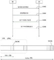
Meanwhile, in the next generation RAT (radio access technology), a self-contained subframe is considered to minimize a data transmission delay. Fig. 15 exemplarily shows a structure of a self-contained subframe. In fig. 15, a shaded area indicates a DL control area, and a black portion indicates a UL control area. The no-mark region may be used for DL or UL data transmission. Since DL transmission and UL transmission are sequentially performed in a single subframe, it is possible to transmit DL data and receive UL ACK/NACK in a subframe. Since the time taken for data retransmission is reduced in the case where a data transmission error occurs, the delivery delay of the final data can be minimized.
As an example of configurable/settable self-contained subframe types, at least the following 4 seed frame types can be considered. The intervals are listed in chronological order.
DL control interval + DL data interval + GP (guard period) + UL control interval
-DL control interval + DL data interval
-DL control interval + GP + UL data interval + UL control interval
-DL control interval + GP + UL data interval
In the DL control interval, PDFICH, PHICH, and PDCCH can be transmitted, and in the DL data interval, PDSCH can be transmitted. In the UL control interval, PUCCH can be transmitted, and in the UL data interval, PUSCH can be transmitted. The GP provides a time interval during which the BS and the UE switch from Tx mode to Rx mode or from Rx mode to Tx mode. Some OFDM symbols at the time of switching from DL to UL in the subframe may be set to GP.
Examples
In case of the existing LTE system, if the size of DL data (i.e., TBS) becomes equal to or greater than a predetermined level, a bitstream to be transmitted through the PDSCH (i.e., TB) is segmented into a plurality of CBs, and channel coding and CRC are applied CB by CB [ see fig. 9 ]. If the UE fails to receive (i.e., decode) any one of the CBs included in the single TB, the UE reports HARQ-ACK feedback corresponding to the TB to the BS as NACK. By doing so, the BS retransmits all CBs corresponding to the TB. That is, the HARQ operation for DL data in the existing LTE/LTE-a is performed based on scheduling/transmission in TB units from the BS and HARQ-ACK feedback configuration in TB units from the UE corresponding thereto.
Meanwhile, a next generation RAT (hereinafter, referred to as a new RAT) system can basically have a wider system (carrier) BW (bandwidth) than LTE, so that it is highly likely that a TBS (or a maximum TBS) becomes larger than LTE. Therefore, the number of CBs configuring a single TB may become larger than that in LTE. Therefore, if HARQ-ACK feedback in TB units is performed in the new RAT system as in the existing system, retransmission scheduling in TB units is accompanied even in the case where a decoding error (i.e., NACK) is generated for only a few CBs, and thus, resource use efficiency may be reduced. Also, in the new RAT system, by allocating some (symbols) of resources for transmitting delay-insensitive data type 1 (e.g., enhanced mobile broadband (eMBB)) having a large time interval (TTI), delay-sensitive data type 2 (e.g., ultra-reliable low-latency communication (URLLC)) having a small TTI can be transmitted in a manner of puncturing data type 1. By including such an operation, a decoding error (i.e., NACK) concentrated on a specific portion in a plurality of CBs configuring a single TB may occur for data type 1 due to the influence of an interference signal having a time selective characteristic.
In view of the properties of the new RAT system, the present invention proposes a method of performing (retransmission) scheduling in CB or CBG (CB group) units and configuring/transmitting HARQ-ACK feedback in CB/CBG units. In detail, the present invention proposes a method of configuring a CBG, a method of configuring HARQ-ACK (hereinafter, referred to as a/N) feedback, a method of operating a reception soft buffer of a UE, a method of handling a specific mismatch situation, and the like.
For clarity, the methods presented herein are grouped into various embodiments for ease of illustration, which can be used in combination.
First, abbreviations/terms used in the present invention are described as follows.
-TBS: TB size. Total number of bits of configuration TB
-CB: code block
-CB size: total number of bits configuring a CB
-CBG: and (5) code block groups. All CBs (configuring a single TB) may be configured as a single CBG, or some of the CBs may be configured as a single CBG, or each CB may be configured as a single CBG.
-A/N: a HARQ-ACK response. That is, this may mean ACK, NACK, or DTX. DTX indicates the case of missing PDCCH. In the case of ACK, the a/N bit may be set to 1, and in the case of NACK, the a/N bit may be set to 0. This may be used equivalently to HARQ-ACK or ACK/NACK.
-CBG based a/N: the CRC is not attached to the CBG, so the A/N for the CBG can be generated based on the error check results of the CBs in the CBG. For example, if all CBs in a CBG are successfully detected, the UE sets an a/N response (or a/N bit) to the CBG to ACK, AND if any one CB in the CBG is not successfully detected, the UE may set an a/N response (or a/N bit) to the CBG to NACK [ logical AND ]. The A/N payload of the CBG of the TB includes a plurality of A/N (response) bits, and each A/N (response) bit corresponds to the CBG of the TB by 1: 1.
-CBG based retransmission: in response to the CBG-based a/N, TB retransmission can be performed in units of CBGs. For example, in case of retransmitting a TB to a UE, the BS can perform retransmission only for a CBG receiving NACK from the UE. In doing so, in case that the retransmission of the TB corresponds to the same HARQ process as the previous transmission of the TB, the CB in the CBG remains the same as in case of the initial transmission of the TB.
-CBG size: number of CBGs configured
-CBG index: an index for identifying the CBG. Depending on the context, a CBG index may be equivalently used as a CBG with a corresponding index.
-symbol: this may mean OFDMA symbols or SC-FDMA symbols unless distinguished separately.
Floor (X): a decreasing function. This means the largest integer equal to or smaller than X.
-ceiling (x): a raising function. This means the smallest integer equal to or greater than X.
-mod (a, B): this means the remainder of dividing a by B.
(X) method of configuring CB
1) Method X-1: given the number of bits "Cn" configuring a single CB, Cm CBs are configured based on the number of bits "Cn".
The number of bits Cn configuring a single CB may be predefined as a single same value regardless of the TBS, or a different value per TBS (e.g., a value proportional to the TBS), or may be indicated to the UE through semi-static signaling (e.g., RRC signaling) or dynamic signaling (e.g., DCI). Therefore, when the total number of bits configuring the TB is Ck, CBs can be configured, the number of which is Cm floor (Ck/Cn) or Cm ceiling (Ck/Cn). In the former case, only one CB may be configured with (Cn + mod (Ck, Cn)) bits, and each of the remaining (Cm-1) CBs may be configured with Cn bits. In the latter case, only one CB may be configured with mod (Ck, Cn) bits, and each of the remaining (Cm-1) CBs may be configured with Cn bits. In the former case, Cn may mean the minimum number of bits configuring one CB, and in the latter case, Cn may mean the maximum number of bits configuring one CB.
As another method, a method of uniformly allocating the number of bits per CB to all CBs can be applied. Taking the foregoing case as an example, in the case where Cm ═ floor (Ck/Cn) CBs are configured, mod (Ck, Cn) CBs may be configured with (Cn +1) bits, and the remaining CBs may be configured with Cn bits. Also, in the case of configuring Cm ═ ceiling (Ck/Cn) CBs, (Cn-mod (Ck, Cn)) CBs may be configured with (Cn-1) bits, and the remaining CBs can be configured with Cn bits. In the former case, Cn may mean the minimum number of bits configuring one CB, and in the latter case, Cn may mean the maximum number of bits configuring one CB.
Meanwhile, if the above method is applied, at least one specific CB (hereinafter, referred to as a small CB) among the total number Cm of CBs may be configured with a small number of bits less than the remaining other CBs (hereinafter, referred to as regular CBs). Therefore, a scheme of grouping Cm CBs having unequal sizes into M CBGs may be required. Specifically, there may be a case where the total number of CBs "Cm" becomes a multiple of the CBG number "M" and a case where the total number of CBs "Cm" does not become a multiple of the CBG number "M". The following CB grouping scheme can be considered for each case. Hereinafter, the CBG size may mean the number of CBs per CBG. Meanwhile, if Cm is not a multiple of M, the size of each CBG may be different, and the size difference between CBGs may be limited to a maximum of 1 CB.
Cm is a multiple of M (all CBGs are equal in size)
-option 1-1: small CBs are configured to be maximally distributed to all CBGs
-options 1-2: small CBs are configured to maximally belong to a minority of partial CBGs
Case where Cm is not a multiple of M (the size of each CBG may be different)
-option 2-1: small CBs are configured to belong to as large CBGs as possible
-option 2-2: small CBs are configured to belong to as small a CBG as possible
-option 2-3: applying option 1-1 or option 1-2
For example, in a case where Cm is 7 and CB indices 1/2/3/4/5/6/7 are respectively configured with 5/5/5/5/5/5/2 bits, a CBG configuration where M is 3 can be considered. Here, if option 2-1 is applied, the CB indexes 1,2,3,4, and 5,6,7 can be configured as the CBG index 1/2/3, respectively. If option 2-2 is applied, the CB indices 1,2,3,4, 5, and 6,7 can be configured as CBG indices 1/2/3, respectively. As another example, in a case where Cm is 7 and CB indices 1/2/3/4/5/6/7 are respectively configured with 5/5/5/5/4/4/4 bits, a CBG configuration where M is 3 can be considered. Here, if option 2-1 is applied, the CB indexes 1,2,3,4, and 5,6,7 can be configured as the CBG index 1/2/3, respectively. If option 2-2 is applied, the CB indices 1,2,3,4, 5, and 6,7 can be configured as CBG indices 1/2/3, respectively. On the other hand, if option 1-1 is applied, the CB indices 1,2,5, 3,6, and 4,7 can be configured as CBG indices 1/2/3, respectively, and if option 1-2 is applied, the CB indices 1,2,3,4, and 5,6,7 can be configured as CBG indices 1/2/3, respectively.
Additionally, by configuring CBGs corresponding to portions where decoding reliability is as low as possible to include CBs as small as possible, the size of CBGs having a high retransmission probability can be reduced as much as possible. For example, a case where decoding reliability may be low may include a case where a CB size of a radio signal is relatively small, a case where a radio signal is far from a DMRS on a time axis, a case where a radio signal is far from CSI feedback timing, or a case where a radio signal is mapped to an (OFDMA/SC-FDMA) symbol adjacent to an SRS (or PUCCH, PRACH). For this, the CBG can be configured as follows.
a) The regular CB is configured in units of X bits from the low CB index, and then the small CB is configured in units of Y bits from the specific CB index (Y < X).
b) The regular CBs are configured by bundling in units of M CBs starting from a low CBG index (sequentially starting from CBs of the low CB index), and then the small CBs are configured by bundling in units of K CBs starting from a specific CBG index (K < M). Here, as set forth in the foregoing description, the size difference between CBGs may be limited to a maximum of 1 CB (e.g., M ═ K + 1). According to a) and b), the CBG of higher index may have a relatively smaller CBG size than the CBG of lower index, and may include more small CBs even if the CBG size is the same.
c) Signals are mapped in a frequency-first (or time-first) scheme sequentially starting from CBGs of low CBG index. Here, the CBG of lower index may be mapped to a resource of relatively higher decoding reliability than the CBG of higher index.
Meanwhile, in the case of "Cn > Ck", all bits of the TB are configured as a single CB, and one CB including Ck bits can be configured.
2) Method X-2: given the total number of CBs, "Cm," each CB is configured in Cn bits based on this Cm.
The total number of CBs "Cm" may be predefined as the same single value regardless of the TBS, or a different value per TBS (e.g., a value proportional to the TBS), or may be indicated to the UE through semi-static signaling (e.g., RRC signaling) or dynamic signaling (e.g., DCI). For example, if the total number of bits configuring the TB is Ck, each CB can be configured in units of Cn ═ floor (Ck/Cm) bits or Cn ═ ceiling (Ck/Cm) bits. In the former case, only one CB can be configured with (Cn + mod (Ck, Cn)) bits, while each of the remaining (Cm-1) CBs can be configured with Cn bits. In the latter case, only one CB can be configured with mod (Ck, Cn) bits, while each of the remaining (Cm-1) CBs can be configured with Cn bits. In the former case, Cn may mean the minimum number of bits configuring one CB, and in the latter case, Cn may mean the maximum number of bits configuring one CB.
As another method, a scheme of uniformly allocating the number of bits per CB to all CBs can be applied. Taking the foregoing case as an example, if CBs are configured in units of Cn ═ floor (Ck/Cm) bits, mod (Ck, Cm) CBs are configured with (Cn +1) (or ceiling (Ck/Cm)) bits, and the remaining (Cm — mod (Ck, Cm)) CBs can be configured with Cn bits. If the CBs are configured in units of Cn ═ ceiling (Ck/Cm) bits, (Cm-mod (Ck, Cm)) CBs are configured with (Cn-1) (or floor (Ck/Cm)) bits, and the remaining mod (Ck, Cm) CBs can be configured with Cn bits. In the former case, Cn may mean the minimum number of bits configuring one CB, and in the latter case, Cn may mean the maximum number of bits configuring one CB.
3) Method X-3: given the minimum number of bits "Tm" to configure a CB, the CB is configured based on the Tm.
Each CB configuring one TB may be set to be configured with at least Tm bits. For example, if TBS is assumed to be Ck, then the maximum Cm value "Cm.max" satisfying the relationship "Ck/Cm ≧ Tm" is calculated, and the operation of segmenting the corresponding TB into Cm.max CBs can be considered.
4) Method X-4: if the number of CBs is equal to or greater than a certain level, CB unit scheduling and grouping among the CBs are performed.
Only when the total number of CBs "K" configuring one TB is equal to or greater than Ts, the CB unit or CBG unit (retransmission) scheduling can be set/defined to be applied to the corresponding TB. Also, if the total number of CBs "K" is equal to or greater than Tg, a plurality of CBs can be set/defined as a group to configure one CBG (e.g., Ts < Tg). Here, the number of bits Cn configuring one CB may be predefined or given through specific signaling (e.g., RRC signaling, DCI).
(A) Method for configuring CBG
1) Method A-1: given the number of CBs "N" configuring a single CBG, M CBGs are configured based on the number of CBs "N".
The CB number "N" configuring a single CBG may be predefined as a single same value regardless of TBS, or a different value per TBS (e.g., a value proportional to TBS), or may be indicated to the UE through semi-static signaling (e.g., RRC signaling) or dynamic signaling (e.g., DCI). For example, when the total number of CBs configuring the TB is K, M-floor (K/N) or M-ceiling (K/N) CBGs can be configured. In the former case, only one CBG may be configured with (N + mod (K, N)) CBs, and each of the remaining (M-1) CBGs may be configured with N CBs. In the latter case, only one CBG may be configured with mod (K, N) CBs, and each of the remaining (M-1) CBGs may be configured with N CBs. In the former case, N may mean a minimum CB number configuring one CBG, and in the latter case, N may mean a maximum CB number configuring one CBG. Meanwhile, the UE can configure and transmit a/N bits per CBG.
As another method, a method of uniformly distributing the number of CBs per CBG to all CBGs can be applied. Taking the foregoing case as an example, in the case of configuring M ═ floor (K/N) CBGs, mod (K, N) CBGs may be configured with (N +1) CBs, and the remaining CBGs may be configured with N CBs. Also, in case of configuring M ═ ceiling (K/N) CBGs, (N-mod (K, N)) CBGs may be configured with (N-1) CBs, and the remaining CBGs may be configured with N CBs. In the former case, N may mean a minimum CB number configuring one CBG, and in the latter case, N may mean a maximum CB number configuring one CBG.
Meanwhile, if N > K, all CBs configuring the TB belong to a single CBG, and one CBG including K CBs can be configured.
2) Method A-2: given the total number of CBGs, "M", each CBG is configured in units of N CBs based on M.
The total number of CBGs "M" may be predefined as the same single value regardless of the TBS, or a different value per TBS (e.g., a value proportional to the TBS), or may be indicated to the UE through semi-static signaling (e.g., RRC signaling) or dynamic signaling (e.g., DCI). The UE is able to identify/configure CBGs from CBs of the TB based on the total number of CBGs "M". For example, if the total number of CBs configuring the TB is K, each CBG can be configured in units of N floor (K/M) or N ceiling (K/M) CBs. In the former case, only one CBG may be configured with (N + mod (K, N)) CBs, and each of the remaining (M-1) CBGs may be configured with N CBs. In the latter case, only one CBG may be configured with mod (K, N) CBs, and the remaining (M-1) CBGs may be configured with N CBs, respectively. In the former case, N may mean a minimum CB number configuring one CBG, and in the latter case, N may mean a maximum CB number configuring one CBG. Meanwhile, the UE can configure and transmit a/N bits per CBG. For example, the UE can configure M a/N bits for the TB, and each of these a/N bits may indicate an a/N result of the corresponding CBG.
As another method, a scheme of uniformly distributing the number of CBs per CBG to all CBGs can be applied. Taking the foregoing case as an example, in the case of CBG configuration in units of N ═ floor (K/M) CBs, mod (K, M) CBGs are configured with (N +1) (or ceiling (K/M)) CBs, and the remaining (M-mod (K, M)) CBGs can be configured with N (or floor (K/M)) CBs. Further, in the case of CBG configuration in units of N-ceiling (K/M) CBs, (M-mod (K, M)) CBGs may be configured with (N-1) (or floor (K/M)) CBs, and the remaining mod (K, M) CBGs may be configured with N (or ceiling (K/M)) CBs. In the former case, N may mean a minimum CB number configuring one CBG, and in the latter case, N may mean a maximum CB number configuring one CBG.
Meanwhile, if M > K, each CB becomes one CBG, and a total number of K CBGs can be configured. In this case, scheme 1) can be considered: in a state where all a/N feedback is configured with M bits, (M-K) bits not corresponding to an actual CBG are treated as NACK or DTX, or scheme 2): the a/N feedback itself is configured with only K bits corresponding to the actual CBG.
Fig. 16 shows a signal transmission process according to the present invention.
Referring to fig. 16, the UE can receive information on the number M of code block groups per transport block from the BS through upper layer signaling (e.g., RRC signaling) [ S1602 ]. Thereafter, the UE can receive an initial data transmission from the BS (through the PDSCH) [ S1604 ]. Here, the data includes a transport block including a plurality of code blocks, and the plurality of code blocks can be grouped into one or more code block groups. Here, some of the code block groups may include ceiling (K/M) code blocks, and the remaining code block groups may include flooding (K/M) code blocks. K indicates the number of code blocks in the data. Thereafter, the UE can feed back CBG-based a/N information on data to the BS S1606, and the BS can perform data retransmission based on the code block group S1608. The a/N information can be transmitted through PUCCH or PUSCH. Here, the a/N information includes a plurality of a/N bits of data, and each a/N bit can indicate each a/N response of the data generated in units of code block groups. The payload size of the a/N information can be kept the same based on M regardless of the number of code block groups of the configuration data.
3) Method A-3: CBG configuration based on tree structure (or nested structure) for CBG number "M" and CBG size "N
CBGs can be configured with a tree structure for a total number of CBGs "M" (e.g., M1, M2..) and a CBG size "N" (e.g., N1, N2.). In this case, a plurality of mutually different CBG configurations based on a plurality of mutually different (M, N) combinations can be set for one TB (size). Consider the CBG configuration in the case of (M1, N1) and (M2, N2) for different (M, N) combinations from each other, if M1<M2, then can be set to N1>N2. Also, one CBG in the case of (M1, N1) can be configured to include at least one CBG in the case of (M2, N2). In contrast, one CBG in the case of (M2, N2) can be configured to belong only to a specific CBG in the case of (M1, N1). Also, M2 may be set to a multiple of M1, or/and N1 may be set to a multiple of N2. M may be set to 2 m (m ═ 0, 1.). Meanwhile, one (or more) of an index regarding M, N or an (M, N) combination or an available CBG index referring to all (M, N) combinations can be indicated to the UE through semi-static signaling (e.g., RRC) or dynamic signaling (e.g., DCI). The UE can configure and transmit a/N bits per CBG configured to correspond to the corresponding index. M and N may be predefined as the same single value regardless of TBS, or as different values per TBS (e.g., values proportional to TBS).
For example, assuming that the total number of CBs configuring the TB is K ═ 16 and each CB is indexed to K ═ 0,1.. 15, a scheme of setting the number of CBGs to M ═ 1,2,4,8,16} and setting each corresponding CBG size to N ═ K/M ═ {16,8,4,2,1} can be considered [ nested CBG example 1 ].
a) If (M, N) ═ 1,16, only 1 CBG is configured, and the corresponding CBG includes all 16 CBs.
b) If (M, N) ═ 2,8, 2 CBGs are configured, and each CBG includes 8 CBs different from each other. In this case, one CBG includes 2 CBGs in the case of (M, N) ═ 4, 4.
c) If (M, N) ═ 4,4 CBGs are configured, and each CBG includes 4 CBs different from each other. In this case, one CBG includes 2 CBGs in the case of (M, N) ═ 8, 2.
d) If (M, N) ═ 8,2, 8 CBGs are configured, and each CBG includes 2 CBs different from each other.
e) If (M, N) ═ 16,1, 16 CBGs are configured, and each CBG includes only 1 CB different from each other.
As in the above example, in a state where a plurality of (M, N) combinations different from each other and the number/size of CBGs according thereto are pre-configured/specified, one (or more) of an index of a specific M, a specific N, or a (M, N) combination or an available CBG index with reference to all (M, N) combinations can be indicated to the UE. In the above example, corresponding to the case where M, N or (M, N) combinations that are available are set to 5 in total, and CBG indexes (corresponding to the sum of the available M values {1,2,4,8,16 }) that are available for all (M, N) combinations are set to 31 in total. The UE can perform decoding and corresponding a/N feedback configuration/transmission in a state assuming CBG configuration corresponding to M index and/or N index for scheduled DL data (e.g., TB or CBG).
By generalizing the present method, for CBS configurations in the case of (M1, N1) and (M2, N2) corresponding to different (M, N) combinations from each other, it is possible to set a plurality of CBG configurations for one TB (size) only under the condition that N1 ≧ N2 is set if M1< M2. For example, assuming that the total number of CBs configuring the TB is K ═ 6, in a state where each CB is indexed with K ═ 0,1.. 5, a scheme of setting the number of CBGs to M ═ 1,2,3,6} and setting the CBG size corresponding to each CBG number to N ═ K/M ═ 6,3,2,1} can be considered [ nested CBG example 2 ].
a) If (M, N) ═ 1,6, only 1 CBG is configured, and the corresponding CBG includes all 6 CBs.
b) If (M, N) ═ 2,3, 2 CBGs are configured, and each CGB includes 3 CBs different from each other. For example, the CB index sets 0,1,2 and 3,4,5 configure 1 CGB, respectively.
c) If (M, N) ═ 3,2, 3 CBGs are configured, and each CGB includes 2 CBs different from each other. For example, the CB index sets 0,1,2,3, and 4,5 configure 1 CBG, respectively.
d) If (M, N) ═ 6,1, 6 CBGs are configured, and each CBG includes only 1 CB different from each other.
As another example, assuming that the total number of CBs configuring the TB is K ═ 9, in a state where each CB is indexed with K ═ 0,1.. 8, a scheme of setting the CBG number to M ═ 1,2,3,6} and setting the CBG size corresponding to each CBG number to N ═ 9, (5 or 4),3, (2 or 1) } [ nested CBG example 3] can be considered.
a) If (M, N) ═ 1,16, only 1 CBG is configured, and the corresponding CBG includes all 9 CBs.
b) If (M, N) ═ 2,5, or 4, a total of 2 CBGs are configured, one CBG including 5 CBs, and the other CBG including 4 CBs. For example, the CB index sets 0,1,2,3,4 and 5,6,7,8 configure one CBG, respectively.
c) If (M, N) ═ 3,3 CBGs are configured, and each CBG includes 3 CBs different from each other. For example, the CB index sets 0,1,2,3,4, 5 and 6,7,8 configure a CBG, respectively.
d) If (M, N) ═ 6,2, or 1, a total of 6 CBGs are configured. Each of 3 CBGs among the 6 CBGs includes 2 CBs, and each of the other 3 CBGs includes 1 CB. For example, the CB index sets 0,1,2,3,4, 5,6,7, and 8 configure one CGB, respectively.
In the case of nested CBG example 2/example 3, a total of 12 (1 +2+3+6) CBGs configured can be indexed (based on 4 different (M, N) combinations). Based on this, the BS indicates the CBG of the retransmission scheduling (through DCI), and/or the UE can configure and transmit a/N feedback of the indicated CBG.
Meanwhile, by considering DCI overhead for scheduling target CBG indication and/or UCI overhead for corresponding a/N feedback configuration, the total number of CBG indexes L configured in a nested form may be set equally per TBS, or the L value per TBS may be set such that bit overhead for CBG indication is equal per TBS (e.g., such that the value of ceiling (log2(L)) is equal).
4) Method A-4: the CBs belonging to a specific number of symbol sets (and a specific number of RB sets) are configured as one CBG
In a state in which a time interval (and/or a frequency interval) for transmitting a TB is partitioned into a plurality of symbol sets (hereinafter, referred to as Symbol Groups (SGs)) (and/or a plurality of RB sets (hereinafter, referred to as RB groups (RBGs)), CBs transmitted through each SG (and/or each RBG) may be configured as one CBG.
Also, for the number of symbols configuring one SG or the total number of SGs configured within the TB transmission time interval (and/or the number of RBs configuring one RBG or the total number of RBGs configured within the TB transmission frequency interval), the scheme of configuring CBGs to have a tree structure as in method a-3 is also possible. On the basis of the nested CBG example 1/2/3, assuming that the total number of symbols (or the number of RBs) configuring the TB is K16, 6 or 9, for example, each symbol (or RB) can be indexed by K0 ~ 15, K0 ~ 5 or K0 ~ 8. In this state, a plurality of SGs (or RBGs) having a nested structural relationship with each other can be configured in a form similar to the nested CBG example 1/2/3. Also, the size/number of SG (and/or RBG) may be predefined to the same single value regardless of TBS, or predefined to a different value per TB (e.g., a value proportional to TBS).
Meanwhile, if one CB is mapped/transmitted across multiple SGs (and/or RBGs), the corresponding CB may be defined as: option 1) is included in the CBG corresponding to the SG with the lowest or highest symbol index (and/or the RBG with the lowest or highest RB index); or option 2) is included in the CBG corresponding to the SG (and/or RBG) including the most coded bits of the corresponding CB.
As another method, in terms of CBG configuration/indication for (retransmission) scheduling in the BS, if one CB is mapped/transmitted across a plurality of SGs (and/or RBGs), the corresponding CB can be set to be included in all of the plurality of CBGs corresponding to the corresponding plurality of SGs (or RGB). On the other hand, in terms of a/N feedback configuration per CBG in the UE, the UE is operable to configure and transmit a/N bits per CBG in a state in which a corresponding CB is included only in a CBG corresponding to a specific one of a corresponding plurality of SGs (or RBGs). In this case, the UE (in case of a/N feedback configuration) can select a specific one of CBGs including a corresponding CB as follows.
1) When the decoding result of the corresponding CB is NACK (in terms of scheduling, among all of the plurality of CBGs including the corresponding CB), if there is a CBG of a CB including NACK even though the corresponding CB is excluded, one of such CBGs is selected (applied based on option 1/2). If no such CBG exists, one of all of the plurality of CBGs (including the corresponding CB in terms of scheduling) can be selected (applied based on option 1/2).
2) When the decoding result of the corresponding CB is ACK, it is also possible to select one of all the plurality of CBGs (including the corresponding CB in terms of scheduling) (applied based on the option 1/2).
Meanwhile, if a plurality of CBGs including the same one CB are simultaneously scheduled, the corresponding CB can operate to be transmitted only once. For example, the respective CBs may be sent in a manner that is included in only a particular one of the respective plurality of CBGs (based on the option 1/2 application).
By generalizing the above-described scheme, the proposed scheme can be applied to a case where one CB is set to be commonly included in a plurality of CBGs in terms of CBG configuration/indication for BS scheduling, and operates such that the corresponding CB can be included in only a specific one of the plurality of CBGs in terms of UE CBG-by-CBG configuration a/N feedback. For example, when the total number of K CBs is configured as M CBGs, all CBGs can be set to equally include N (═ ceiling (K/M)) CBs, which counts as the number of CBs per CBG. In this case, some CBGs among the M CBGs may be set to include a common specific CB. For example, two random CBGs in a CBG set that are less in number than M may include one CB in common, and the number of CBs included in the two random CBGs may be in total (M-mod (K, M)).
As another scheme, in order to prevent one CB from being mapped/transmitted across a plurality of SGs (and/or RBGs) or in order to make the number of data bits belonging to each CBG match each other as equally as possible, the following method can be considered. Assuming that the scheduled TBS is a bits, and assuming that the SG or RBG (generically CBG) number allocated to the corresponding TBS is M, each CBG can be first allocated (a/M), ceiling (a/M) or floor (a/M) data bits. Next, in a state where the number of data bits allocated per CBG is replaced with the number of bits Ck corresponding to the TBS in method X-1/2/3, a plurality of CBs belonging to each CBG can be configured by applying method X-1/2/3. Meanwhile, the coded bits for a single CBG may be mapped/transmitted only on a single SG or RBG.
Meanwhile, a scheme of changing the number of symbols configuring one SG according to the number of symbols allocated to data transmission and/or the number of RBs (or TBS) allocated to data transmission is also possible. For example, the number of symbols per SG (in order to make the number of CBGs the same as possible) can be configured to increase as the number of symbols allocated to data transmission increases. Also, the number of symbols per SG (in order to make CBG size the same as much as possible) can be configured to decrease as the number of RBs (or TBS) allocated for data transmission increases. Similarly, a scheme of changing the number of RBs configuring one RBG according to the number of RBs allocated for data transmission and/or the number of symbols (or TBS) allocated for data transmission is also possible. For example, the number of RBs per RBG (in order to make the number of CBGs the same as possible) can be configured to increase as the number of RBs allocated for data transmission increases. Also, the number of RBs per RBG (in order to make CBG size the same as much as possible) can be configured to decrease as the number of RBs (or TBS) allocated for data transmission increases.
5) Method A-5: the total number of CBGs "M" and the CBG size "N" are configured TBS by TBS "
The (M, N) combination for CBG configuration can be set (differently) at each TBS. Based on the maximum value m.max among the M values set per TBS, the number of DCI bits indicated by CBG for performing data scheduling and/or UCI payload size for the corresponding a/N feedback configuration can be determined. For example, the CBG indication information and/or the a/N payload size can be set to m.max, ceiling (m.max/K) or ceiling (log) 2 (m.max)) bits. Here, K may be a positive integer, for example, K ═ 2.
As an additional method, first, if a set of (M, N) combinations applied per TBS is named a TBS-CBG table, a scheme of indicating one of a plurality of TBS-CBG tables to a UE through semi-static signaling (e.g., RRC signaling) or dynamic signaling (e.g., DCI) in a state where the plurality of TBS-CBG tables are predefined/preset can be considered. In this case, the (M, N) combination corresponding to the same TBS may be differently configured between a plurality of TBS-CBG tables. Accordingly, the UE determines an (M, N) combination corresponding to the TBS indicated by the DL/UL scheduling DCI by referring to the indicated TBS-CBG table, and is then operable to perform DL/UL data transmission/reception and a/N feedback transmission based on the determined (M, N) combination.
As another method, in a state where the total TBS set is divided into a plurality of TBS ranges, a CBG configuration method different per TBS range can be applied. For example, for TBS range 1, the CBG number "M" can be configured identically by method a-2 or per TBS, as opposed to being configured differently by method a-1 or per TBS (or, the CBS size "N" being configured equally), for TBS range 2. In this case, TBS range 2 can be configured with a larger TBS than the TBS belonging to TBS range 1, considering DCI overhead and/or UCI payload. As yet another approach, the same CBG configuration (e.g., CBG number/size) is applied to each TBS range, but the CBG number/size, etc., is configured differently between TBS ranges. For example, the CBG number "M" is configured identically by method a-2 or per TBS for each of TBS ranges 1 and 2, but different values of M can be set between TBS range 1 and TBS range 2. In this case, M of TBS range 2 may be set to a value greater than M of TBS range 1. As another example, the CBG size "N" is identically configured by method a-1 or per TBS for each of TBS ranges 1 and 2, but different values of N can be set between TBS range 1 and TBS range 2. In this case, N of TBS range 2 may be set to a value greater than N of TBS range 1.
6) Method A-6: applying interleaving between CBs belonging to the same CBG before mapping of data to resources
By taking into account the effect of interference with a specific (time-selective) pattern (e.g. URLLC puncturing operation), inter-CB interleaving can be applied between multiple CBs (coded bits) belonging to the same CBG before the mapping of data to resources (e.g. REs). For example, for a plurality of CBs (coded bits) belonging to one CBG, 1) inter-CB interleaving is additionally applied in a state where intra-CB interleaving is first applied within each CB, or 2) (if a CBG-based HARQ operation is set), only inter-CB interleaving can be applied in a state where intra-CB interleaving is omitted. Here, the mapping of data to resources includes RE mapping based on a frequency-first manner.
In all the previously proposed methods, M, N and K may be respectively set/indicated to the same value for TBSs different from each other, or respectively set/indicated to different values for TBSs different from each other, or respectively set/indicated to the same value for part (e.g., N) and respectively set/indicated to different values for the remaining parts (e.g., M and K) according to TBS. Further, when considering a scheme of performing one DL data scheduling/transmission across a plurality of slots, in the method proposed in the foregoing, one Symbol Group (SG) can be configured/set on a slot basis (in this case, a symbol index is applied by being substituted for a slot index).
(B) HARQ-ACK feedback method
1) Method B-1: configuring/transmitting a (minimum) range including all NACKs on CBG index as feedback
In a state where a CBS configuration scheme (e.g., CBG number/size) is given, considering a decoding error (i.e., NACK) across consecutive CBG indexes due to time-selective interference, the UE can: 1) feeding back a CBG index corresponding to the first NACK (on the CBG index) and a CBG index corresponding to the last NACK to the BS, or 2) feeding back a CBG index corresponding to the first NACK and a distance between the first NACK and the last NACK. Here, by using an RIV (resource indication value) indication scheme applied to UL resource allocation type 0 or a combination index scheme applied to UL resource allocation type 1, 1) and 2) can be signaled. In this case, the CBG configuration scheme may include method A-1/2/3/4.
As an additional method, the UE directly selects one of a plurality of CBG configuration schemes (e.g., CBG number/size), based on the selected CBG configuration, 1) the UE determines a (minimum) CBG range including NACK and then feeds back the corresponding NACK CBG range to the BS together with the selected CBG configuration information, or 2) the UE configures individual a/N bits per CBG and then feeds back the configured a/N bits (together with the selected CBG configuration information) to the BS
And (5) the BS. In this case, the CBG configuration scheme may also include method A-1/2/3/4.
Additionally, the above method may also be applied to CBG scheduling from the BS. Specifically, 1) the first CBG index and the last CBG index to be transmitted (or retransmitted), or 2) the first CBS index and the total number of CBGs "L" to be transmitted (or retransmitted) can be indicated by the DL data scheduling DCI. In this case, the UE can operate (receive) in a state in which it is assumed/recognized that 1) a CBG set corresponding to some index between indexes including the first CBG index and the last CBG index, or 2) a CBG set corresponding to the following consecutive L indexes including the first CBG index is scheduled.
2) Method B-2: feeding back a (minimum-sized) CBG comprising all NACKs in a tree-structured CBG configuration
In a state where a plurality of CBG configurations (e.g., (M, N) combinations) are given based on the tree structure as in method a-3, the UE can operate in a manner of selecting a specific CBG configuration and determining a CBG index including all NACKs based on the selected CBG configuration, and then feeding back the NACK CBG index together with the selected CBG configuration information to the BS. Here, preferably, the NACK CBG is selected as one CBG having the smallest size while including all NACKs. That is, the UE can operate in such a manner: selecting a specific CBG configuration enabling a single CBG of a minimum size to include all NACKs from among a plurality of CBG configurations having a tree structure, determining a CBG index including all NACKs based on the selected CBG configuration, and feeding back the determined CBG index (together with the selected CBG configuration information) to the BS.
Similarly, given a plurality of CBG configurations (based on different SG (/ RBG) sizes/numbers from each other) with an SG-based (and/or RBG-based) tree structure as in method a-4, the UE may operate in such a way: the method includes selecting one CBG configuration based on a specific SG (/ RBG), determining a CBG index including all NACKs based on the selected CBG configuration, and feeding back the NACK CBG index to the BS together with selected CBG configuration (or corresponding SB (/ RBG) configuration) information.
Additionally, the above method may be applied to CBG scheduling from the BS. Specifically, in a state in which a plurality of CBG configurations having a tree structure (e.g., M and/or N (combination) or SG (/ RBG) size/number) as in method a-3 or method a-4 are given, one CBG index based on one specific CBG configuration can be indicated by DL data scheduling DCI. In this case, the UE can operate (receive) in a state of assuming/recognizing that the CBG set belonging to the corresponding CBG index is scheduled through the corresponding DCI.
3) Method B-3: keeping CBG configuration and corresponding A/N configuration the same during one HARQ process
In order to prevent unnecessary RLC level DL data retransmission due to a/N error of a specific CBG, CBG configuration (used for retransmission (CBG) scheduling (indication) in the BS) and a/N feedback configuration corresponding to the corresponding CBG configuration can remain the same when one HARQ process is performed (i.e., until the end of the process). In particular, the CBG configuration and corresponding a/N feedback configuration initially applied/indicated to DL data scheduling/transmission with a particular HARQ process ID can operate to be kept the same until the respective HARQ process ends (e.g., until the decoding of all CBs for the TBs configuring the DL data is successful, or before a new DL data scheduling (NDI handover) with the same HARQ process ID starts). Here, the initial application/indicated CBG and a/N configuration information may be indicated to the UE through semi-static signaling (e.g., RRC signaling) or dynamic signaling (e.g., DCI, (initial) DL data scheduling DCI). If the initial applied/indicated CBG and a/N configuration information is indicated through semi-static signaling (e.g., RRC signaling), the CBG and a/N configuration information is semi-statically fixed and can remain the same throughout all HARQ processes until there is new RRC signaling.
Meanwhile, the UE may configure and feed back a/N bits per CBG, and operate to feed back NACK for the corresponding CBG until each CBG is successfully decoded (regardless of whether there is scheduling of the corresponding CBG). Further, the UE may operate to feed back an ACK for a corresponding CBG from a time when decoding is successful (regardless of whether there is scheduling of the corresponding CBG, and until the corresponding HARQ process is terminated).
Fig. 17 illustrates a signal transmission process of the present invention. Fig. 17 assumes a case where the number of CBGs per TB is set to 3 and TBs are transmitted (retransmitted) for the same HARQ process (i.e., operation before the HARQ process corresponding to the TB is assumed to be terminated).
Referring to fig. 17, the UE can receive CBG # 0 and CBG # 2 of a TB (e.g., HARQ process # a) from the BS S1702. Here, the TB of step S1702 may be an initial transmission or retransmission corresponding to HARQ process # a. Also, assume that CBG # 1 has never been successfully decoded before. In this case, according to the decoding result, the UE transmits a/N information corresponding to 3 CBGs to the BS [ S1704], sets a/N information regarding CBG # 1 as NACK, and sets a/N information regarding CBGs # 0 and CBGs # 2 as ACK or NACK according to the result of decoding. Thereafter, the BS retransmits the TBs (e.g., HARQ process # a) in CBG units, and the UE can receive CBG # 1 and CBG # 2 for the corresponding TBs S1706. In this case, the UE transmits a/N information corresponding to 3 CBGs to the BS [ S1708], but sets a/N information on CBG # 0 as ACK due to previous successful decoding of CBG # 0, and sets a/N information on CBG # 1 and CBG # 2 as ACK or NACK according to the decoding result.
4) Method B-4: setting corresponding A/N transmission time delay differently according to the number of scheduled CBGs
The corresponding a/N transmission time delay (i.e., the time interval between DL data reception and the corresponding a/N feedback transmission) can be set differently according to the number of CBs or CBGs simultaneously scheduled for the same TB (size). Specifically, the smaller the number of scheduled CBs or CBGs, the corresponding a/N delay may be set to be small. For example, the corresponding a/N delay in case of scheduling partial CBs or CBGs may be set smaller than in case of scheduling all TBs, i.e. all CBs. Also, the corresponding a/N delay with a smaller number of CBGs scheduled may be set smaller, assuming the same CBG size. Also, in case the number of scheduled CBGs is the same, the corresponding a/N delay in case of configuring a smaller CBG size may be set to be smaller.
5) Method B-5: setting CBG configuration (CBG number/size) differently between DL data scheduling and A/N feedback
CBG configurations (e.g., CBG number/size) applied to DL data scheduling/transmission and CBG configurations applied to a/N feedback corresponding to respective DL data reception can be differently set. Here, the CBG configuration may be indicated by the DL data scheduling DCI. Specifically, the (M, N) combination for DL data scheduling and the (M, N) combination for a/N feedback configuration may be set to different values, respectively. For example, a combination of (M1, N1) and a combination of (M2, N2) may be set for DL data scheduling and a/N feedback, respectively. Therefore, in the case of comparing case 1 set to M1> M2 (and N1< N2) with case 2 set to M1< M2 (and N1> N2), the number of bits of DCI increases but the number of bits of retransmission DL data resources and a/N feedback may decrease in case 1. In case 2, the number of bits of DCI decreases but the number of bits of retransmission DL data resources and a/N feedback may increase.
6) Method B-6: setting A/N transmission time delay differently from CBG to CBG for a plurality of scheduled CBGs
The a/N transmission time delay for each CBG can be set to be different (i.e., TDM-transmitting the a/N of each CBG) for a plurality of CBGs scheduled simultaneously. Specifically, the a/N delay corresponding to the CBG transmitted through a lower symbol (or slot) index may be set to be smaller. Thus, the a/N corresponding to the CBG transmitted through the lower symbol (or slot) index can be fed back through the relatively faster symbol (or slot) timing.
7) Method B-7: A/N feedback configuration corresponding to transmission (retransmission) scheduling for TB units (configured with M CBGs)
The a/N feedback can be performed by indicating to the UE which one of the a/N bit configuration by TB unit or the a/N bit configuration by CBG unit through semi-static signaling (e.g., RRC signaling) or dynamic signaling (e.g., (initial) DL data scheduling DCI). In case of a/N bit configuration of CBG unit, a/N payload size (and PUCCH format for corresponding a/N transmission) can be set through semi-static signaling (e.g., RRC signaling). In this case, the total number of CBGs for the configuration TB can be determined according to a given (fixed) a/N payload size (e.g., M bits). For example, the number of CBGs can be determined as M equal to the number of A/N bits. Therefore, the number of CBGs configuring the TBs may be identically set even for TBSs different from each other, and the number of CBGs configuring one CBG can be differently set according to the TBs (e.g., set to a value proportional to the TBs). Meanwhile, if the total number of CBs configuring the TB is equal to or smaller than a given a/N payload size, the entire a/N feedback can be configured in a manner of allocating a/N bits per CB without grouping the CBs. On the other hand, if the total number of CBs "N" is less than a given a/N payload size "M" (bits), a/N bits are allocated CB-by-CB, and 1) the remaining (M-N) bits allocated to a/N without CB-by-CB are processed as NACKs, or 2) the a/N payload size itself can be changed to N (bits) equal to the total number of CBs.
Meanwhile, for each TBS, the CB number configuring the TB and the CBs configuration based on the CB number (e.g., the total number of CBGs "M" configuring the TB, the number of CBGs "N" configuring a single CBG) can be determined according to a predetermined rule. Also, based on the number of CBGs set for the TB, the a/N payload size and the corresponding PUCCH format can be set. For example, the PUCCH format and the candidate PUCCH resource set for CBG unit a/N transmission can be independently (differently) set for each TBS (the total number of CBGs "M" according to the TBS). Also, the M value and/or the corresponding PUCCH format can be indicated to the UE through semi-static signaling (e.g., RRC signaling) or dynamic signaling (e.g., (DL data scheduling) DCI). For example, in a state where a plurality of (M value, PUCCH format (and candidate PUCCH resource set)) combinations are specified in advance, a specific combination can be indicated by DCI, or the M value and PUCCH format can be independently indicated by RRC and/or DCI, respectively. Meanwhile, if an M value is indicated, a PUCCH format (and a candidate PUCCH resource set) previously assigned to the corresponding M value can be automatically determined. Alternatively, if the PUCCH format is indicated, the M value previously assigned to the corresponding PUCCH format can be automatically determined.
As another approach, the N value and/or the corresponding PUCCH format can be indicated to the UE through semi-static signaling (e.g., RRC signaling) or dynamic signaling (e.g., (DL data scheduling) DCI). For example, in a state where a plurality of N values and a plurality of (M, PUCCH format (and candidate PUCCH resource set)) combinations according to the N values are specified in advance, a specific combination can be indicated by DCI, or the N value and PUCCH format can be independently indicated by RRC signaling and/or DCI, respectively. Meanwhile, if an N value is indicated, a PUCCH format (and a candidate PUCCH resource set) previously assigned to an M value according to the N value can be automatically determined. Alternatively, if the PUCCH format is indicated, the total number of CBGs and the number of CBs per CBG can be automatically determined with reference to an a/N payload size (e.g., M bits) according to the PUCCH format.
8) Method B-8: A/N feedback configuration corresponding to sending (retransmitting) some CBGs (among M CBGs configuring a TB)
In the case of transmission (retransmission) scheduling of L or less CBGs among the total M CBGs configuring the TB (where L < M), the following method can be considered.
Option 1) can apply the same a/N payload size (e.g., M bits) as in the case of a/N feedback corresponding to TB unit transmission (retransmission) (as in method B-7). Thus, in practice, the a/N is mapped to only L bits (corresponding to the CBG for retransmission scheduling), and the remaining (M-L) bits (corresponding to the non-scheduled CBG) are mapped to ACK or NACK according to the corresponding CBG decoding success/failure (as in method B-3) or treated as NACK. Option 2) a/N payload size (and PUCCH format) different from (e.g., smaller than) the case of a/N feedback corresponding to TB unit transmission (retransmission) can be applied. In case of option 2, the a/N payload size (and PUCCH format) can be changed according to the scheduled CBG number "L". For example, the a/N payload may be configured with only L bits.
Here, L may be semi-fixed to a single value through semi-static signaling (e.g., RRC signaling) or dynamically changed through dynamic signaling (e.g., DL data scheduling DCI). In the former case, the CBG indication signaling can be configured as a scheduling DCI by CBG unit so that CBG scheduling can be up to a maximum of L CBGs out of a total of M CBGs. Also, additionally, among the total M CBGs configuring the TB, retransmission scheduling (from the BS) can be performed only for L (L < M) or less CBGs. In this case, if the scheduling target CBG number exceeds L, the BS/UE can perform scheduling (DCI transmission)/a/N feedback in TB units.
Meanwhile, option 1 and option 2 are basically applicable assuming that the CBG configuration initially applied/indicated to TB scheduling/transmission (e.g., the total number of CBGs "M" configuring the TB, the number of CBGs "N" configuring a single CBG) remains uniform during the HARQ process.
Additionally, in case of option 1, the a/N payload size is set with reference to TB unit transmission (retransmission) (e.g., M bits), but in order to configure a/N feedback only for actually scheduled CBGs, CBs belonging to all scheduled L CBGs (each of which is configured with N CBs) are reconfigured to M CBGs (each of which is configured with less than N CBs). Referring to this, it is possible to configure the entire a/N feedback allocated according to the a/N bits of the CBG unit. In this case, the BS can also perform retransmission scheduling by assuming that M CBGs corresponding to a/N feedback correspond to the entire CBG set. Meanwhile, in the case where a UE corresponding to a DL data receiving end or an a/N transmitting end is accompanied by a CB reassembly process, if a NACK-to-ACK error occurs, a mismatch (or performance degradation due to the mismatch) between the UE configured for CBG and a BS may be caused. In view of this problem, the full a/N feedback (payload) can be configured by including an indicator (e.g., 1 bit) for additionally indicating NACK feedback of (presence or absence of) TB units or use of retransmission requests of (presence or absence of) all TBs in addition to the M a/N information per CBG. Based on this, if a CBS configuration mismatch occurs, the UE can map/transmit a corresponding indicator to a state corresponding to "TB unit NACK" or "TB retransmission request". Upon receiving the indicator, the BS can perform TB scheduling again based on the initial CBG configuration before the reassembly.
Meanwhile, in case of CBG retransmission scheduling DCI corresponding to a/N feedback in option 2, the corresponding signaling can be configured by the following form: 1) a retransmitted CBG indication referring to a total number of CBGs "M", irrespective of a change in a/N payload size; or 2) a CBG indication form in a state where a CBG set (equal to or less than M) fed back as NACK by the UE is assumed to be a full CBG configuration.
Also, additionally, it is possible to indicate to the UE through semi-static signaling (e.g., RRC signaling) or dynamic signaling (e.g., (DL data scheduling) DCI): whether the always same (fixed) a/N payload size (and PUCCH format) is applied as option 1 for CBG (retransmission) scheduling regardless of the number of CBGs scheduled, or the a/N payload size (and PUCCH format) that varies (dynamically) according to the number of CBGs scheduled is applied as option 2.
9) Method B-9: A/N feedback of CBG units only when some (of M CBGs configuring TB) are NACK
The a/N feedback of the CBG unit can be configured/transmitted (e.g., individual a/N bits are allocated per CBG) only when the number of CBGs corresponding to NACK among the total M CBGs configuring the TB is equal to or less than L (L < M). Meanwhile, if the number of CBGs for NACK exceeds L, a/N feedback of TB unit can be configured/transmitted. In this case, since a/N feedback of CBG units is configured only for NACKs equal to or less than L, retransmission CBG (index) indication of DCI scheduled by CBG units (retransmission) can configure corresponding signaling by the following form: 1) a form of indication for L or fewer CBGs among the total M CBGs; or 2) a CBG indication form in a state where a CBG set (equal to or less than L) fed back as NACK by the UE is assumed to be a full CBG configuration. For example, when i ═ {1.. L }, all sets of i CBGs out of the total M CBGs are indexed for all values of i, and the UE can feed back one of the respective indices to the BS so as to indicate the CBG set corresponding to NACK.
10) Method B-10: CBG retransmission scheduling and A/N feedback limiting the maximum CBG number to the form of M
In terms of BS scheduling, the BS is operable to configure all CBG configurations with Mr CBGs (Mr ≦ M) and to indicate to the UE to retransmit L CBGs among the Mr CBGs (L ≦ Mr). Here, Mr (and L) may vary at every (retransmission) scheduling instant, as opposed to M having a fixed value during at least one TB transmission or one HARQ process.
In this case, the UE can operate as follows in terms of a/N feedback.
Option 1) the a/N feedback can be configured based on the maximum CBS number "M", if possible. For example, the full a/N payload size is configured with M bits, and (M-L) bits corresponding to CBGs that cannot be actually scheduled may be treated as NACK or DTX.
Option 2) a/N feedback can be configured based on the total number of CBGs "Mr" at the scheduling timing. For example, the full a/N payload size is configured with Mr bits, and (Mr-L) bits corresponding to CBGs that cannot be actually scheduled may be treated as NACK or DTX.
Option 3) a/N feedback can be configured based on the scheduled number of CBGs "L". For example, by configuring the entire a/N payload size with L bits, the a/N bits can be mapped/transmitted per scheduled CBG.
With option 2/3, the a/N payload size can vary depending on the Mr or L value, so that the PUCCH format (and the set of candidate PUCCH resources) for a/N feedback transmission can be altered.
Also, in this case, all Mr CBG configurations in the BS for retransmission scheduling may be configured for configuring all CB sets of the TBs (i.e., all CB sets equal to all TBs) or limited to a specific part of all CBs (i.e., all CBG sets correspond to a part of the TBs). In the former case, the Mr value for a particular scheduling timing of one TB transmission or one HARQ process may be restricted to be always less than or equal to the Mr value of the previous scheduling timing. In the latter case, the specific part of CB may mean: 1) a CB set belonging to L CBGs scheduled with a previous scheduling timing; or 2) a CB set belonging to a CBG fed back as NACK from the UE among the L scheduled CBGs.
11) Method B-11: handling of (subsequent) CBGs that are re-scheduled prior to A/N feedback transmission
Such a situation may occur: CBG retransmissions for a particular TB (hereinafter referred to as subsequent CBGs) are scheduled at some time before a/N feedback (hereinafter referred to as a first a/N) corresponding to the same TB reception is transmitted. In this case, a situation may occur in which: as the decoding end time of the subsequent CBG becomes too late, an operation of transmitting a/N feedback reflecting the reception combination of the subsequent CBG through the first a/N timing may not be performed. Here, the reception combination may mean an operation of: the received signal stored in the buffer is cleared (i.e., refreshed) and then the subsequent CBG is stored. In this case, the UE may: 1) transmitting A/N feedback according to a decoding result of the original TB only at a first A/N time, and performing reception combining on a subsequent CBG (A/N feedback for a subsequent time); or 2) sending an A/N feedback according to a decoding result reflecting a reception combination of a subsequent CBG at a certain time later than the first A/N time by a certain delay. In case 2), the a/N transmission at the first a/N time may be dropped, or only the a/N of the original TB may be transmitted.
Meanwhile, in the UL data scheduling case, it is also possible to schedule (subsequent) CBG retransmission for a specific (or initial) TB at a certain time before the same TB is transmitted in a similar manner as described above. Here, the original TB transmission timing (hereinafter referred to as TX timing 1) and the subsequent CBG transmission timing (hereinafter referred to as TX timing 2) are different from each other, and the TX timing 2 may be indicated as a timing after the TX timing 1. In this case, the UE can transmit only signals remaining after excluding CBGs corresponding to subsequent CBGs from the scheduled original TB signal (e.g., puncturing REs/RBs/symbols mapping the corresponding CBGs) through TX timing 1, and can also completely transmit the retransmission-scheduled subsequent CBGs through TX timing 2.
Also in case of cross-slot scheduling for DL data, (subsequent) CBG retransmissions for a specific (or initial) TB may also be scheduled sometime before the same TB reception in a similar way as described above. Here, the original TB reception time (hereinafter referred to as TX timing 1) and the subsequent CBG reception time (hereinafter referred to as TX timing 2) are different from each other, and TX timing 2 may be indicated as a time after TX timing 1. In this case, the UE can receive only signals (e.g., RE/RB/symbol of the punctured mapped CBG) remaining after excluding the CBG corresponding to the subsequent CBG from the scheduled original TB signal through TX timing 1, and can also completely receive the retransmission-scheduled subsequent CBG through TX timing 2.
(C) Soft buffer operation method
1) Method C-1: determining a minimum buffer size per CB with reference to a sum of numbers of CBs belonging to CBGs corresponding to NACKs
A scheme of a buffer size Bc obtained by dividing a (minimum) buffer size Bt per TB assigned to one HARQ process or one TB by a sum Cn of numbers of CBs belonging to CBGs fed back as NACK (to the BS) by the UE can be considered as a minimum buffer size per CB in terms of UE reception (e.g., Bc ═ Bt/Cn). Specifically, it can be considered to replace C with Cn in the following formula 4. Here, for example, the minimum buffer size per CB may mean the minimum (soft channel) number of bits that the UE should save to the buffer per CB for TB transmission.
[ formula 5]

In this case, there is an advantage in that the minimum buffer size per CB can be increased (for example, because C > Cn) compared to the existing scheme of a/N feedback based on TB units. Also, Cn applied to one HARQ process or one TB transmission can be determined by: 1) only the initial a/N feedback configured by CBG units (CBG with NACK therein) is referred to (i.e., the same Cn is applied until HARQ process termination); or 2) reference to the a/N feedback (CBG of NACK, among others) for each of the a/N transmission time instants (i.e., Cn is determined from the NACK CBG for each scheduling/feedback time instant).
Meanwhile, a scheme can be considered in which Cn of method C-2, i.e., the sum of the numbers of CBs belonging to CBGs whose feedback is NACK or which require retransmission (or fail to receive ACK feedback) in terms of the BS, is applied to equation 5.
2) Method C-2: (Limited/circular buffer) Rate matching operation in BS for retransmission of CBG signals
When (limited/cyclic buffer) rate matching is performed with reference to all CBGs that are fed back (from the UE) as NACKs or need retransmission on the BS side, a mismatch between NACK CBGs on the BS side and NACK CBGs fed back by the UE may be generated due to a/N errors. To eliminate such mismatch, the following operation can be considered.
1) The BS may operate to perform retransmission scheduling (i.e., an operation of not allowing retransmission scheduling for only some NACK CBGs) in common/simultaneously for all CBGs fed back (from the UE) as NACKs (or failing to receive ACK feedback) all the time (the UE operates under a state of assuming/recognizing this), or
2) (although the BS allows an operation of performing retransmission scheduling on some of all NACK CBGs), an operation of indicating to the UE through DL data scheduling DCI that all CBG information (e.g., NACK CBG number/index) that is NACK-fed back or needs retransmission (or that fails to receive ACK feedback) on the BS side is fed back to the UE can be considered.
In this case, the minimum buffer size per CB (for example, Bc ═ Bt/Cn) as the BS transmission side can be determined by dividing the (minimum) buffer size per TB assigned to one HARQ process or one TB by the buffer size Bc belonging to the sum Cn of the CBGs fed back as NACK on the BS side or the numbers of CBs requiring retransmission (or failing to receive ACK feedback). In particular, it can be considered to replace C by Cn in the following formula 2.
[ formula 6]

In this case, compared to the existing scheme in which only TB-unit retransmission is applied, (e.g., because C > Cn) has an advantage of being able to increase the minimum buffer size per CB. Cn applied to one TB transmission can be determined by: 1) determined with reference to the CBG unit retransmission timing that is initially performed (i.e., the same Cn is applied until the HARQ process is terminated); or 2) at each CBG unit retransmission time (i.e., Cn is determined with reference to each time according to the number of CBSs for which the feedback is NACK or needs to be retransmitted (or for which ACK feedback is not received).
Meanwhile, with the data scheduling DCI, if indication information on CBS index transmitted (retransmitted) and buffer refresh indication information per CBG are signaled, signaling of buffer refresh indication information may not be required for CBS index without transmission (retransmission) indication. Here, the buffer flush information may include indication information indicating whether to flush the corresponding buffer by flushing or to combine the received CBG signal with a previously saved CBG signal without flushing the buffer before saving the received CBG signal to the buffer. If the indication is to flush the buffer by flushing the CBG index for which no indication is sent (retransmitted) (or vice versa, the indication is combined without flushing the buffer), the UE can operate in a state in which the corresponding CBG index is asserted/assumed to receive ACK feedback or CBG for which retransmission is not required at the BS side. Conversely, if the indications are combined without flushing the buffer (or vice versa, by flushing the buffer), the UE may not perform any operation on the corresponding CBG index (the receive (Rx) buffer corresponding thereto).
3) Method C-3: applying power offset to A/N feedback PUCCH transmissions according to scheduling of CBG units
The power offset added/applied to the PUCCH transmission carrying a/N feedback configured by the CBG unit can be determined to be a value proportional to the value of option 1/2/3/4/5/6/7. Thus, as the number of CBGs rises in option 1/2/3/4/5/6/7, the corresponding power offset can be added/applied at a greater value.
Option 1) (without distinguishing A/N) total number of CBGs assigned with A/N bits or subject to A/N feedback
Option 2) number of CBGs scheduled from BS
Option 3) number of NACK CBGs (at BS) indicated from BS in method C-2
Option 4) number of NACK CBGs at UE
Option 5) consider the a/N feedback configuration as method B-3, the sum of the number of CBGs for option 2 and the number of CBGs fed back as ACKs although not scheduled
Option 6) sum of CBG number of option 3 and CBG number fed back as ACK although not scheduled
Option 7) the number of remaining CBGs except for the CBG which has been added/applied to the power offset transmitted through the a/N PUCCH by a specific timing as ACK feedback of a certain timing before the specific timing
(D) Mismatch processing method
1) Method D-1: mismatch between A/N information per CBG fed back by UE and CBG scheduled for retransmission from BS
A mismatch between the a/N information per CBG fed back by the UE and the CBG index corresponding thereto that is retransmitted from the BS may occur (due to an a/N error). For example, some CBGs fed back as NACKs by the UE may not be included in CBG indexes scheduled from the BS or/and CBGs already fed back as ACKs may be included therein. In this case, the UE may be configured to perform the following operations.
Option 1) mapping the combined decoded A/N results for CBGs with a previous feedback of NACK among the scheduled CBGs, or
Option 2) to map ACK again (in a state of omitting combining/decoding) for CBG previously fed back as ACK among scheduled CBGs [ see method B-3], or
Option 3) map NACK for all CBGs, or
Option 4) performs NACK feedback for TB units or retransmission request for the entire TB, or option 5) discards the corresponding CBG scheduling DCI.
Meanwhile, if all CBGs previously fed back as NACKs are included in the scheduled CBGs, one of option 1 and option 2 is applied. Otherwise, one of options 3 through 5 may also be applied.
2) Method D-2: mismatch between CRC applied to entire TB and CRC applied in CB and/or CBG units
Among the CRC applied to the entire TB, the CRC applied in CB units, and the CRC applied in CBG units, the Rx CRC check result (e.g., pass/fail) at the UE may be different. Here, if the CRC check result is "pass", it means that the corresponding data block is successfully/correctly detected. If the CRC check result is "fail," it means that the corresponding data block is not successfully/correctly detected.
For example, CRC check results in CB and/or CBG units may all be "pass" (i.e., CB CRC based CRC check pass), but in contrast, the CRC check result for the entire TB may be "fail" (i.e., TB CRC based CRC check fail). In contrast, at least one of the CRC check results in CB and/or CBG units fails (i.e., CB CRC based CRC check fails), but in contrast, the CRC check result for the entire TB may pass (i.e., TB CRC based CRC check passes). In this case, the UE can apply one of option 3 to option 5 of the method D-1. Options 3 to 5 of method D-1 are listed below.
Option 3) maps NACKs for all CBGs.
Option 4) performs NACK feedback in TB units or retransmission request of the entire TB.
Option 5) the corresponding CBG scheduling DCI can be discarded.
As another example, CRC check results in CB units belonging to a particular CBG all pass, but in contrast, CRC check results for the entire corresponding CBG may fail. In contrast, although at least one CRC check result in CB units belonging to a specific CBG fails, the CRC check result of the entire corresponding CBG may pass. In this case, the UE may transmit feedback by mapping the corresponding CBG to NACK, or apply one of option 3 to option 5 of method D-1.
(E) CBG scheduling DCI configuration
1) Method E-1: RV configuration and setting in scheduling (DCI) of CBG units
Regarding the RV field in the (retransmission) scheduling DCI of the CBG unit, 1) only one RV field of the same size as the RV field of the scheduling DCI of the TB unit is configured and the indicated RV value is uniformly applied to the entire CBG of the scheduling (here, the number of branches of the RV value can be configured to be equal to the case of the scheduling in the TB unit), or 2) a separate RV field is configured per CBG but can be configured to have a size smaller than the size of the RV field of the scheduling DCI in the TB unit (however, the number of branches of the RV value can be configured to be smaller than the case of the scheduling in the TB unit).
2) Method E-2: performing retransmission scheduling on some CBGs (of M CBGs configuring a TB)
It is operable to implement retransmission scheduling only for at most L CBGs out of the total M CBGs configuring the TB (L < M). Here, a single value of L can be indicated to the UE through semi-static signaling (e.g., RRC signaling). Therefore, a maximum of L CBGs out of the total of M CBGs can be indicated by the CBG-unit scheduling DCI from the BS, and the scheduling DCI in TB units (or a flag indicating transmission (retransmission) scheduling in TB units in the DCI) can be applied to CBG retransmission scheduling of more than L CBGs. In detail, when i ═ 1.. L }, one such scheme can be considered: the index selects all combinations of i CBGs from the total of M CBGs, and indicates a CBG set/combination corresponding to one of the respective indices to the UE through a CBG retransmission scheduling DCI.
3) Method E-3: using NDI field in scheduling (DCI) of CBG unit
The NDI field can be interpreted differently depending on whether it is a transmission (retransmission) for the entire TB or a retransmission for some CBGs (among all CBGs configuring the TB). For example, once all CBGs configuring a TB are transmitted by the DCI indication, a combination in which the NDI bit is toggled is identified as a schedule for new data transmission. Thus, the case where some of all CBGs are transmitted is indicated by DCI may be considered retransmission (rather than new data), and the NDI field can be used for another specific purpose. As another example, an indicator indicating whether to transmit the entire TB or some CBGs can be directly signaled through DCI. In this case, once transmission of the entire TB is indicated, a combination in which the NDI bit is toggled can be recognized as a schedule for new data transmission. Thus, the latter case (i.e., some indication of CBG transmission) can be considered retransmission and the NDI field can be used for another specific purpose. Meanwhile, if the NDI field is used for another specific purpose, the NDI field can indicate: 1) whether to save the received CBG signal to the Rx buffer corresponding to the corresponding CBG index by combining it with the previously saved signal, or to save the received CBG signal again by flushing the buffer only by refreshing the previously saved signal (i.e., CBG buffer refresh indicator, CBGFI), or 2) the transmitted (retransmitted) CBG (index) (i.e., CBG transmission indicator, CBGTI).
4) Method E-4: use of buffer refresh indicator field in scheduling (DCI) of CBG unit
The buffer flush indicator field can be interpreted differently in case of data retransmission (NDI-toggling not done) or in case of new data transmission (NDI-toggling done). For example, in the case of data retransmission, the original use of a buffer flush indicator may be used to indicate whether the buffer is not flushed by flushing the buffer before the received CBG signals (CBG by CBG) are saved to the buffer or combining the received CBG signals. Meanwhile, in the case of new data transmission, since the buffer refresh operation before the acceptance signal storage is basically assumed as a precondition, the buffer refresh indicator can be used for another specific purpose. In the case where the buffer refresh indicator field is used for another specific purpose, the buffer refresh indicator field may include bits indicating TBS and/or MCS information of the scheduled data. In contrast, the TBS/MCS field includes TBS/MCS information in DCI for scheduling new data transmission, but in contrast, bits configuring a buffer refresh indicator may be included in DCI for scheduling data retransmission.
5) Method E-5: using CBGTI (and CBGFI) fields in scheduling (DCI) of CBG units
Based on the value indicated by the CBGTI field in the DCI (or a combination of this value and another value indicated by the CBGFI field), a buffer flush can be indicated for a particular CBG (set). First, each bit configuring the CBGTI field can be used to individually indicate whether there is transmission (retransmission) of each CBG index. For example, a bit "1" indicates transmission (retransmission) of a CBG (corresponding to the corresponding bit), and a bit "0" indicates non-transmission (retransmission) of the corresponding CBG. In addition, the CBGFI field/bit may be used to indicate whether or not to buffer flush the CBG that is instructed to transmit (retransmit) through the CBGTI field. For example, a bit "1" may indicate that a buffer is flushed (for CBGs that are instructed to be sent (retransmitted)), and a bit "0" may indicate that the corresponding buffer is not flushed.
First, in a state where only the CBGTI field in DCI is configured/set (without separate CBGFI field configuration) [ hereinafter referred to as CBG mode 1], all bits configuring the corresponding CBGTI field (no NDI switching is made) can be indicated as "0". In this case, it is prescribed/acknowledged (by the UE) that a buffer refresh operation is indicated for all CBGs while transmission (retransmission) is indicated for all CBGs configuring a given TB. Thus, the UE is operable to save the newly received CBG signal to the buffer after refreshing the signal previously saved to the buffer. Meanwhile, in CBG mode 1, all bits configuring the CBGTI field (in a state where NDI is not toggled) can be indicated as "1". In this case, in a state where the buffer refresh operation is not instructed, it is prescribed/acknowledged (by the UE) that transmission (retransmission) of all CBGs for configuring a given TB is instructed.
Second, in a state where both the CBGTI field and the CBGFI field are configured/set in DCI [ hereinafter, referred to as CBG mode 2], all bits configuring the CBGTI field (NDI switching is not performed) can be indicated as "0". In this case, what is specified/acknowledged (by the UE) is that the transmission (retransmission) of all CBGs for a given TB configured is indicated. In this state, additionally, if the CBGFI bit is indicated as "0", it can be specified/asserted (by the UE) that a buffer refresh operation is indicated for certain CBGs (hereinafter CBG subgroup 1) [ case 1 ]. If the CBGFI bit is indicated to be "1," then it can be specified/asserted that a buffer refresh operation is indicated for certain other CBGs (hereinafter CBG subgroup 2) [ case 2 ]. CBGs belonging to CBG subgroup 1 and CBG subgroup 2 can be configured completely exclusive of each other or partially identical to each other (while the union of the corresponding CBGs is the entire CBG set). Meanwhile, in CBG mode 2, if all bits configuring the CBGTI field are indicated as "1" and the CBGFI bit is indicated as "1" (or "0") (in a state where NDI is not toggled), it is prescribed/asserted (by the UE) that a buffer flush operation is indicated for all CBGs while transmission (retransmission) of all CBGs configuring a given TB is indicated.
Meanwhile, in consideration of early termination of a TB decoding operation in the UE, 1) decoding is sequentially performed on a pair of CBs by pair in a CBG-by-CBG alternating manner for a plurality of CBGs (e.g., decoding is performed in an order of CB1 in CBG-1 ═ CB1 in CBG-2.. CB1 in CBG-M ═ CB2 in CBG-1.. or 2) decoding is sequentially performed per CBG (index) by CBG unit (e.g., decoding is performed in an order of CB in CBG-1 ═ CB in CBG-2.. or). If a NACK CBG is generated, a NACK can be fed back (by skipping the decoding operation) for all CBGs (indexes) after that.
Meanwhile, for DL/UL data transmitted based on the SPS scheme, retransmission scheduling in CBG units and CGB-by-CGB a/N feedback configuration operations may not be applied/configured. Therefore, retransmission scheduling in CBG units and CBG-by-CBG a/N feedback configuration operation can be applied/configured only for DL/UL data transmission based on general scheduling rather than SPS scheme. Further, for SPS-based DL/UL data transmission, scheduling in TB units and a/N feedback per TB (i.e., TB level) (e.g., configuring/transmitting 1 bit a/N for one TB) operation can be applied/configured. Also, for the DL/UL data scheduled by the UE (group) CSS-based DCI (or a specific DCI format, e.g., TM common DCI format similar to the DCI format 0/1a in LTE (e.g., commonly set/used for different TMs)) transmission (and/or Msg3 scheduled from RAR accompanying the random access procedure and Msg4 transmitted for contention resolution purposes), the CBG-by-CBG retransmission scheduling and CBG-by-CBG a/N feedback configuration operations may not be applied/configured. Accordingly, retransmission scheduling in CBG units and CBG-by-CBG a/N feedback configuration operation can be applied/configured only for DL/UL data transmission scheduled by DCI (or TM-specific DCI format set/used only for a specific TM) transmission not based on CSS but based on USS. On the other hand, for DL/UL data (and/or Msg3/4) transmission that is scheduled by CSS-based DCI (or TM common DCI format) transmission, scheduling in TB units and a/N feedback operation per TB (TB level) (i.e., configuring a/N feedback of TB level) may be applied/configurable.
Meanwhile, in case of configuring retransmission scheduling in units of CBGs and CBG-by-CBG a/N feedback configuration operation, if a TB level a/N feedback is configured according to the above-described reason (or other reasons, such as UE bundling CBG-by-CBG a/N in order to reduce a/N payload, or indication of a/N bundling operation by BS), the a/N scheme can be changed according to whether a/N for only a single TB is transmitted without multiplexing or a plurality of a/N for a plurality of TBs [ case 1] is transmitted with multiplexing. For example, in case 1, after configuring 1-bit a/N payload, AN can be transmitted by using PUCCH format/resource supporting small payload (e.g., maximum 2 bits). On the other hand, in case 2, if the number of CBGs per TB is set to N, option 1) a/N for the TB is identically and repeatedly mapped to N bits, or option 2) a/N for the TB can be mapped to 1 bit corresponding to a specific (e.g., lowest) CBG index. Meanwhile, in case of configuring retransmission scheduling in CBG units and CBG-by-CBG a/N feedback configuration operation, option 1) and option 2) may be applied regardless of case 2.
In case 2, by configuring a multi-bit a/N payload including N bits of a/N corresponding to a corresponding TB, the UE can transmit a/N using a PUCCH format/resource supporting a large payload (e.g., 3 or more bits). The multi-bit a/N payload may include a/N information corresponding to a plurality of TBs. For example, the multi-bit a/N payload may include a plurality of N-bit a/ns corresponding to the plurality of TBs.
Meanwhile, considering the case where the intentional URLLC puncturing operation as described above is applied in a co-channel inter-cell environment, it may be preferable to minimize the interference effect caused by a URLLC signal transmitted in a specific cell on a DMRS signal used for DL/UL data reception in another cell. For this, an operation of delivering/exchanging symbol position information for DMRS transmission in each cell and/or symbol position information for URLLC (puncturing) transmission in each cell between cells can be considered.
The method proposed by the present invention may not be limited to DL data scheduling and transmission scenarios, but may also be applied identically/similarly to UL data scheduling and transmission scenarios (e.g., CB/CBG configuration according to TB, UL data transmission timing setting, CBG scheduling DCI configuration, etc.). In contrast, in the method proposed by the present invention, DL data (scheduling DCI) can be replaced with UL data (scheduling DCI).
Fig. 18 illustrates a BS and a UE applicable to the present invention.
Referring to fig. 18, the wireless communication system includes a BS 110 and a UE 120. When the wireless communication system includes a relay, the BS or the UE can be replaced by the relay.
The foregoing embodiments are achieved by combinations of structural elements and features of the present invention in a predetermined manner. Each structural element or feature may be considered optional unless otherwise noted. Each structural element or feature may be practiced without being combined with other structural elements or features. Further, the embodiments of the present invention may be configured by combining some structural elements and/or features. The order of operations described in the embodiments of the present invention may be changed. Some structural elements or features of one embodiment may be included in another embodiment and may be replaced with corresponding structural elements or features of another embodiment. Also, it is apparent that claims having no explicit citation relation among specific claims may be combined to constitute the embodiment or add new claims through amendment after the application is filed.
The embodiments of the present invention have been described based on data transmission and reception between a BS (or eNB) and a UE. Such a transmission and reception relationship may also be identically/similarly extended to transmission and reception of signals between the UE and the relay or the BS and the relay. The specific operations that have been described as being performed by the BS may be performed by an upper node of the BS as appropriate. In other words, it is apparent that various operations performed for communication with a UE in a network including a BS and a plurality of network nodes may be performed by the BS or network nodes other than the BS. The BS may be replaced by terms such as fixed station, node B, e node b (enb), access point, and the like. Also, the term UE may be replaced with terms such as UE (ms), Mobile Subscriber Station (MSS), and the like.
Embodiments according to the present invention may be implemented by various means, such as hardware, firmware, software, or a combination thereof. If the embodiments according to the present invention are implemented by hardware, the embodiments of the present invention may be implemented by one or more Application Specific Integrated Circuits (ASICs), Digital Signal Processors (DSPs), Digital Signal Processing Devices (DSPDs), Programmable Logic Devices (PLDs), Field Programmable Gate Arrays (FPGAs), processors, controllers, micro-controllers, microprocessors, and the like.
If the embodiment according to the present invention is implemented by firmware or software, the embodiment of the present invention may be implemented by a module, a procedure, or a function which performs the functions or operations as described above. The software codes may be stored in memory units and then driven by processors. The storage unit may be provided inside or outside the processor to transmit and receive data to and from the processor via various well-known devices.
It will be apparent to those skilled in the art that the present invention may be embodied in other specific forms without departing from the spirit or essential characteristics thereof. The present embodiments are, therefore, to be considered in all respects as illustrative and not restrictive. The scope of the invention should be determined by reasonable interpretation of the appended claims and all changes which come within the equivalent scope of the invention are intended to be embraced therein.
INDUSTRIAL APPLICABILITY
The present invention is applicable to a UE, a BS, or other devices of a wireless mobile communication system.
Claims (16)
1. A method of transmitting hybrid ARQ HARQ information based on a code block group CBG by a communication device in a wireless communication system, the method comprising:
performing a first reception of a transport block, TB; and
transmitting a first HARQ response for each of a plurality of CBGs of the TB in response to the first reception of the TB,
performing a second reception of at least one of the plurality of CBGs retransmitted to the TB of a communication device in response to the first HARQ response; and
transmitting a second HARQ response for each of the plurality of CBGs of the TB in response to the second receiving,
wherein the second HARQ response includes HARQ information bits for a first CBG successfully decoded in the first reception of the TB and the HARQ information bits for the first CBG are generated as an acknowledgement ACK regardless of a detection of the first CBG in the second reception.
2. The method of claim 1, wherein the first CBG comprises a CBG that was not received at the second reception.
3. The method of claim 1, wherein the first and second light sources are selected from the group consisting of,
wherein the plurality of CBGs of the TB includes a second CBG that was not received at the second reception and was not successfully decoded in the first reception of the TB, and an
Wherein the second HARQ response includes HARQ information bits for the second CBG and the HARQ information bits for the second CBG are mapped to a negative acknowledgement, NACK.
4. The method of claim 1, wherein each CBG comprises one or more code block CBs, a respective CB-based cyclic redundancy check, CRC, is appended to each CB, and a TB-based CRC is appended to the TB.
5. The method of claim 1, wherein the CBGs for a total of M configured TBs are received through radio resource control, RRC, signaling and the number of HARQ responses is M.
6. The method of claim 1, wherein the second reception and the first reception of the TB share a same HARQ process.
7. The method of claim 1, wherein the wireless communication system comprises a third generation partnership project, 3GPP, based wireless communication system.
8. The method of claim 1, wherein a Negative Acknowledgement (NACK) is transmitted for each of the plurality of CBGs of the TB if all of the plurality of CBGs that configure the TB successfully pass a Cyclic Redundancy Check (CRC), but if a CRC check of the TB is unsuccessful.
9. A communication apparatus for transmitting hybrid ARQ HARQ information based on a code block group, CBG, in a wireless communication system, the communication apparatus comprising:
a Radio Frequency (RF) module; and
a processor, wherein the processor is configured to:
performing a first reception of a transport block TB, an
Transmitting a first HARQ response for each of a plurality of CBGs of the TB in response to the first reception of the TB,
performing a second reception of at least one of the plurality of CBGs retransmitted to the TB of a communication device in response to the first HARQ response; and
transmitting a second HARQ response for each of the plurality of CBGs of the TB in response to the second receiving,
wherein the second HARQ response includes HARQ information bits for a first CBG successfully decoded in the first reception of the TB and the HARQ information bits for the first CBG are generated as an acknowledgement ACK regardless of a detection of the first CBG in the second reception.
10. The communications apparatus of claim 9, wherein the first CBG comprises a CBG that was not received at the second reception.
11. The communication device as set forth in claim 9,
wherein the plurality of CBGs of the TB includes a second CBG that was not received at the second reception and was not successfully decoded in the first reception of the TB, and an
Wherein the second HARQ response includes HARQ information bits for the second CBG and the HARQ information bits for the second CBG are mapped to a negative acknowledgement, NACK.
12. The communication apparatus of claim 9, wherein each CBG comprises one or more code block CBs, a respective CB-based cyclic redundancy check, CRC, is appended to each CB, and a TB-based CRC is appended to the TB.
13. The communications apparatus of claim 9, wherein a total of M CBGs of the configured TBs are received via radio resource control, RRC, signaling and a number of HARQ responses is M.
14. The communications apparatus of claim 9, wherein the second reception and the first reception of the TB share a same HARQ process.
15. The communications apparatus of claim 9, wherein the wireless communication system comprises a third generation partnership project, 3GPP, based wireless communication system.
16. The communications apparatus of claim 9, wherein a Negative Acknowledgement (NACK) is transmitted for each of the plurality of CBGs of the TB if all of the plurality of CBGs that configure the TB successfully pass a Cyclic Redundancy Check (CRC), but if a CRC check of the TB is unsuccessful.
Priority Applications (4)
| Application Number | Priority Date | Filing Date | Title |
|---|---|---|---|
| CN202110510129.7A CN113411892B (en) | 2017-03-08 | 2018-03-08 | Method and apparatus for transmitting and receiving radio signal in wireless communication system |
| CN202210851485.XA CN115361100A (en) | 2017-03-08 | 2018-03-08 | Method and apparatus for transmitting and receiving radio signal in wireless communication system |
| CN202210857257.3A CN115361102A (en) | 2017-03-08 | 2018-03-08 | Method and apparatus for transmitting and receiving radio signal in wireless communication system |
| CN202210851661.XA CN115361101A (en) | 2017-03-08 | 2018-03-08 | Method and apparatus for transmitting and receiving radio signal in wireless communication system |
Applications Claiming Priority (13)
| Application Number | Priority Date | Filing Date | Title |
|---|---|---|---|
| US201762468380P | 2017-03-08 | 2017-03-08 | |
| US62/468,380 | 2017-03-08 | ||
| US201762469546P | 2017-03-10 | 2017-03-10 | |
| US62/469,546 | 2017-03-10 | ||
| US201762475860P | 2017-03-23 | 2017-03-23 | |
| US62/475,860 | 2017-03-23 | ||
| US201762501048P | 2017-05-03 | 2017-05-03 | |
| US62/501,048 | 2017-05-03 | ||
| US201762520562P | 2017-06-16 | 2017-06-16 | |
| US62/520,562 | 2017-06-16 | ||
| US201762566339P | 2017-09-30 | 2017-09-30 | |
| US62/566,339 | 2017-09-30 | ||
| PCT/KR2018/002743 WO2018164495A1 (en) | 2017-03-08 | 2018-03-08 | Method and apparatus for transmitting and receiving wireless signal in wireless communication system |
Related Child Applications (4)
| Application Number | Title | Priority Date | Filing Date |
|---|---|---|---|
| CN202110510129.7A Division CN113411892B (en) | 2017-03-08 | 2018-03-08 | Method and apparatus for transmitting and receiving radio signal in wireless communication system |
| CN202210857257.3A Division CN115361102A (en) | 2017-03-08 | 2018-03-08 | Method and apparatus for transmitting and receiving radio signal in wireless communication system |
| CN202210851485.XA Division CN115361100A (en) | 2017-03-08 | 2018-03-08 | Method and apparatus for transmitting and receiving radio signal in wireless communication system |
| CN202210851661.XA Division CN115361101A (en) | 2017-03-08 | 2018-03-08 | Method and apparatus for transmitting and receiving radio signal in wireless communication system |
Publications (2)
| Publication Number | Publication Date |
|---|---|
| CN110392995A CN110392995A (en) | 2019-10-29 |
| CN110392995B true CN110392995B (en) | 2022-08-12 |
Family
ID=63718416
Family Applications (5)
| Application Number | Title | Priority Date | Filing Date |
|---|---|---|---|
| CN202210851485.XA Pending CN115361100A (en) | 2017-03-08 | 2018-03-08 | Method and apparatus for transmitting and receiving radio signal in wireless communication system |
| CN202110510129.7A Active CN113411892B (en) | 2017-03-08 | 2018-03-08 | Method and apparatus for transmitting and receiving radio signal in wireless communication system |
| CN202210857257.3A Pending CN115361102A (en) | 2017-03-08 | 2018-03-08 | Method and apparatus for transmitting and receiving radio signal in wireless communication system |
| CN202210851661.XA Pending CN115361101A (en) | 2017-03-08 | 2018-03-08 | Method and apparatus for transmitting and receiving radio signal in wireless communication system |
| CN201880016978.3A Active CN110392995B (en) | 2017-03-08 | 2018-03-08 | Method and apparatus for transmitting and receiving radio signal in wireless communication system |
Family Applications Before (4)
| Application Number | Title | Priority Date | Filing Date |
|---|---|---|---|
| CN202210851485.XA Pending CN115361100A (en) | 2017-03-08 | 2018-03-08 | Method and apparatus for transmitting and receiving radio signal in wireless communication system |
| CN202110510129.7A Active CN113411892B (en) | 2017-03-08 | 2018-03-08 | Method and apparatus for transmitting and receiving radio signal in wireless communication system |
| CN202210857257.3A Pending CN115361102A (en) | 2017-03-08 | 2018-03-08 | Method and apparatus for transmitting and receiving radio signal in wireless communication system |
| CN202210851661.XA Pending CN115361101A (en) | 2017-03-08 | 2018-03-08 | Method and apparatus for transmitting and receiving radio signal in wireless communication system |
Country Status (14)
| Country | Link |
|---|---|
| US (10) | US11012221B2 (en) |
| EP (4) | EP4102752A1 (en) |
| JP (3) | JP6833971B2 (en) |
| KR (7) | KR101943327B1 (en) |
| CN (5) | CN115361100A (en) |
| BR (1) | BR112019000645B1 (en) |
| CA (2) | CA3146623A1 (en) |
| CL (1) | CL2019002425A1 (en) |
| ES (2) | ES2892448T3 (en) |
| MX (2) | MX2019000572A (en) |
| PH (1) | PH12019501897A1 (en) |
| RU (1) | RU2735328C1 (en) |
| SG (2) | SG11201900089XA (en) |
| TW (3) | TWI691221B (en) |
Families Citing this family (51)
| Publication number | Priority date | Publication date | Assignee | Title |
|---|---|---|---|---|
| US10574404B2 (en) * | 2016-04-22 | 2020-02-25 | Lg Electronics Inc. | Method for transmitting or receiving a HARQ-ACK signal in wireless communication system, and device therefor |
| KR20180013171A (en) * | 2016-07-28 | 2018-02-07 | 삼성전자주식회사 | Method and apparatus for managing hybrid automatic repeat request process in mobile communication system |
| US11012221B2 (en) | 2017-03-08 | 2021-05-18 | Lg Electronics Inc. | Method and apparatus for transmitting and receiving radio signals in a wireless communication system |
| US10771196B2 (en) * | 2017-03-20 | 2020-09-08 | Qualcomm Incorporated | Techniques for signaling compressed HARQ or retransmission information between a base station and a user equipment |
| JP6928091B2 (en) * | 2017-03-23 | 2021-09-01 | エルジー エレクトロニクス インコーポレイティド | A method of transmitting confirmation response information of a terminal in a wireless communication system and a device that supports it. |
| CN108631950B (en) * | 2017-03-23 | 2023-11-07 | 华为技术有限公司 | Method and device for sending feedback information |
| US20180287752A1 (en) * | 2017-03-29 | 2018-10-04 | Kt Corporation | Method and apparatus for configuring transport block to transmit data |
| WO2018185896A1 (en) * | 2017-04-05 | 2018-10-11 | 株式会社Nttドコモ | User terminal and wireless communication method |
| CN108696943B (en) * | 2017-04-12 | 2022-11-08 | 株式会社Kt | Method for transmitting and receiving data channel for new radio and apparatus using the same |
| WO2018201352A1 (en) * | 2017-05-03 | 2018-11-08 | Oppo广东移动通信有限公司 | Data re-transmission control method and related product |
| CN114826490A (en) * | 2017-05-05 | 2022-07-29 | 北京三星通信技术研究有限公司 | Scheduling method, HARQ-ACK feedback method and corresponding equipment |
| CN108809531B (en) | 2017-05-05 | 2020-10-27 | 电信科学技术研究院 | Data transmission method, terminal and base station |
| CN110582967B (en) * | 2017-05-05 | 2022-05-13 | 摩托罗拉移动有限责任公司 | Scheduling transmission of data |
| CN108809530A (en) * | 2017-05-05 | 2018-11-13 | 电信科学技术研究院 | A kind of transmission method, terminal device and base station |
| CN108988984B (en) * | 2017-05-31 | 2021-07-09 | 株式会社Kt | Method for retransmitting transport blocks for new radio and apparatus using the same |
| JP2019004246A (en) * | 2017-06-13 | 2019-01-10 | シャープ株式会社 | Terminal device, base station device, and communication method |
| CN109150380B (en) * | 2017-06-16 | 2020-12-08 | 华为技术有限公司 | Data transmission method, network equipment and terminal equipment |
| JP2019004362A (en) * | 2017-06-16 | 2019-01-10 | シャープ株式会社 | Terminal device, base station device, and communication method |
| CN107359970A (en) * | 2017-06-16 | 2017-11-17 | 宇龙计算机通信科技(深圳)有限公司 | Hybrid automatic repeat-request feedback method and relevant apparatus |
| WO2019006578A1 (en) * | 2017-07-03 | 2019-01-10 | 南通朗恒通信技术有限公司 | Method and device for use in user equipment and base station of multi-antenna communications |
| CN109391406A (en) * | 2017-08-10 | 2019-02-26 | 株式会社Ntt都科摩 | Data transmission method for uplink, confirmation signal sending method, user equipment and base station |
| US11166293B2 (en) * | 2017-08-11 | 2021-11-02 | Qualcomm Incorporated | CBG indication with multi-TTI grant |
| US11601223B2 (en) * | 2017-08-18 | 2023-03-07 | Qualcomm Incorporated | Systems and methods for HARQ transmission and retransmission using multiple code words |
| US11336395B2 (en) * | 2017-08-18 | 2022-05-17 | Panasonic Intellectual Property Corporation Of America | Terminal and communication method |
| US10644842B2 (en) * | 2017-09-06 | 2020-05-05 | Qualcomm Incorporated | Multiplexing code block group level and transport block level transmission and new data indications |
| US10673566B2 (en) * | 2017-09-07 | 2020-06-02 | Sharp Kabushiki Kaisha | Determining DCI format |
| WO2019063534A1 (en) * | 2017-09-28 | 2019-04-04 | Fraunhofer-Gesellschaft zur Förderung der angewandten Forschung e.V. | Transmission of data by multiple users over shared resources |
| US10805916B2 (en) * | 2017-11-15 | 2020-10-13 | Sharp Laboratories Of America, Inc. | Procedure, user equipment and base station for code block group based hybrid automatic repeat request process |
| US11240849B2 (en) * | 2017-11-24 | 2022-02-01 | Sony Group Corporation | Early data transmission in a random access procedure |
| KR20190060605A (en) * | 2017-11-24 | 2019-06-03 | 삼성전자주식회사 | Method and apparatus for data mapping in wireless communication system |
| US11258532B2 (en) * | 2018-01-11 | 2022-02-22 | Kt Corporation | Method and apparatus for data modulation and coding for new radio |
| WO2019140635A1 (en) * | 2018-01-19 | 2019-07-25 | Lenovo (Beijing) Limited | Uplink control information retransmission |
| CN110351774B (en) * | 2018-04-04 | 2022-07-15 | 中兴通讯股份有限公司 | Communication method, communication device, terminal, base station, and storage medium |
| WO2020019118A1 (en) * | 2018-07-23 | 2020-01-30 | Lenovo (Beijing) Limited | Cbg-based retransmission |
| US11483095B2 (en) | 2018-10-02 | 2022-10-25 | Qualcomm Incorporated | Time varying code block group granularity for hybrid automatic receipt request processes in new radio-unlicensed operations |
| EP3861654A4 (en) * | 2018-10-03 | 2022-07-06 | Telefonaktiebolaget Lm Ericsson (Publ) | Remote interference mitigation for physical uplink shared channel (pusch) |
| US11212829B2 (en) * | 2018-10-05 | 2021-12-28 | Qualcomm Incorporated | Uplink processing techniques for reduced uplink timelines in wireless communications |
| WO2020084524A1 (en) * | 2018-10-23 | 2020-04-30 | Telefonaktiebolaget Lm Ericsson (Publ) | In band signaling of control information and corresponding payload in a physical channel |
| US11259334B2 (en) * | 2019-01-30 | 2022-02-22 | Qualcomm Incorporated | Code-block-based communication for random access channel |
| US11570646B2 (en) * | 2019-02-12 | 2023-01-31 | Qualcomm Incorporated | Reduced monitoring state |
| US11239959B2 (en) * | 2019-03-19 | 2022-02-01 | Qualcomm Incorporated | Methods and apparatus for code block level feedback |
| US11336401B2 (en) | 2019-03-21 | 2022-05-17 | Electronics And Telecommunications Research Institute | Method of retransmission for downlink transmission in wireless communication system and apparatus for the same |
| US11317413B2 (en) * | 2019-06-11 | 2022-04-26 | Qualcomm Incorporated | Data packet grouping for traffic awareness in new radio |
| US11336399B2 (en) * | 2019-09-09 | 2022-05-17 | Qualcomm Incorporated | Code block reordering for retransmissions |
| CN115694731B (en) * | 2019-11-08 | 2023-11-10 | 中兴通讯股份有限公司 | Control information indication method, communication node and computer readable storage medium |
| WO2021196247A1 (en) * | 2020-04-04 | 2021-10-07 | Qualcomm Incorporated | Methods and apparatus for dci transmission over pdsch |
| CN112804706B (en) * | 2020-12-31 | 2022-07-26 | 联想未来通信科技(重庆)有限公司 | Communication link detection method and device |
| KR102595899B1 (en) * | 2021-05-11 | 2023-10-30 | 엘지전자 주식회사 | Method and device for transmitting and receiving HARQ-ACK information in a wireless communication system |
| US20220399959A1 (en) * | 2021-06-15 | 2022-12-15 | Qualcomm Incorporated | Transport block grouping for higher bands |
| CN114071572B (en) * | 2021-11-02 | 2023-06-30 | 中国联合网络通信集团有限公司 | Code block segmentation method, device and computer readable storage medium |
| US20230134718A1 (en) * | 2021-11-02 | 2023-05-04 | Qualcomm Incorporated | Dynamic code block group (cbg) enabling and signaling of maximal number of cbgs |
Citations (8)
| Publication number | Priority date | Publication date | Assignee | Title |
|---|---|---|---|---|
| CN101615986A (en) * | 2008-06-27 | 2009-12-30 | 华为技术有限公司 | A kind of data transmission method, device and communication system |
| CN101667900A (en) * | 2008-09-02 | 2010-03-10 | 中兴通讯股份有限公司 | Method for feeding back HARQ |
| CN102318254A (en) * | 2009-04-10 | 2012-01-11 | 上海贝尔股份有限公司 | Method for requesting retransmission, method for retransmission and devices thereof |
| CN105024781A (en) * | 2014-04-30 | 2015-11-04 | 中兴通讯股份有限公司 | Feedback information processing method, apparatus and system |
| CN105515719A (en) * | 2014-09-24 | 2016-04-20 | 中兴通讯股份有限公司 | Data transmission method and device |
| CN105515733A (en) * | 2014-09-24 | 2016-04-20 | 中兴通讯股份有限公司 | Feedback method and device |
| CN105530071A (en) * | 2014-09-29 | 2016-04-27 | 普天信息技术有限公司 | Uplink signal coding method based on code block segmentation and terminal |
| CN106411480A (en) * | 2010-11-22 | 2017-02-15 | Lg电子株式会社 | Method and apparatus for transmitting ack/nack for downlink transmission in wireless communication system |
Family Cites Families (81)
| Publication number | Priority date | Publication date | Assignee | Title |
|---|---|---|---|---|
| US8315210B2 (en) * | 2002-08-13 | 2012-11-20 | Koninklijke Philips Electronics N.V. | ARQ system with status and packet acknowledgement |
| WO2005027456A1 (en) | 2003-09-18 | 2005-03-24 | Nomura Research Institute Co., Ltd. | Communication system, communication device, and data retransmission control method |
| US7584397B2 (en) | 2004-06-10 | 2009-09-01 | Interdigital Technology Corporation | Method and apparatus for dynamically adjusting data transmission parameters and controlling H-ARQ processes |
| CN100586052C (en) * | 2005-12-17 | 2010-01-27 | 华为技术有限公司 | Method and system for transmitting data |
| US8379738B2 (en) * | 2007-03-16 | 2013-02-19 | Samsung Electronics Co., Ltd. | Methods and apparatus to improve performance and enable fast decoding of transmissions with multiple code blocks |
| US7885176B2 (en) | 2007-06-01 | 2011-02-08 | Samsung Electronics Co., Ltd. | Methods and apparatus for mapping modulation symbols to resources in OFDM systems |
| EP2166689A4 (en) | 2007-07-04 | 2013-11-20 | Nec Corp | Multicarrier mobile communication system |
| US8555148B2 (en) | 2007-09-18 | 2013-10-08 | Samsung Electronics Co., Ltd. | Methods and apparatus to generate multiple CRCs |
| KR101412174B1 (en) | 2007-10-17 | 2014-06-26 | 삼성전자주식회사 | Method and apparatus for decoding in portable communication system |
| US20090313516A1 (en) * | 2008-06-16 | 2009-12-17 | Interdigital Patent Holdings, Inc. | Enhanced hybrid automatic repeat request for long term evolution |
| KR101421253B1 (en) | 2008-07-04 | 2014-07-18 | 삼성전자주식회사 | Apparatus and method for supporting synchronous hybrid automatic repeat request in a broadband wireless communication system |
| JP2010147755A (en) * | 2008-12-18 | 2010-07-01 | Sharp Corp | Transmitter, receiver and communication system |
| JP5212539B2 (en) * | 2009-03-25 | 2013-06-19 | 富士通株式会社 | Radio communication system, mobile station apparatus, base station apparatus, and radio communication method in radio communication system |
| CN102308010B (en) * | 2009-03-26 | 2014-04-09 | 本田技研工业株式会社 | Automatic heat treatment method for metal ring |
| US8942166B2 (en) * | 2010-02-12 | 2015-01-27 | Google Technology Holdings LLC | Method for providing a contention based uplink channel |
| EP2537386B1 (en) * | 2010-02-15 | 2019-09-18 | Telefonaktiebolaget LM Ericsson (publ) | Contention based access optimization |
| JP5714693B2 (en) | 2010-03-22 | 2015-05-07 | サムスン エレクトロニクス カンパニー リミテッド | Multiplexing control and data information from user equipment on physical data channel |
| CN102404072B (en) | 2010-09-08 | 2013-03-20 | 华为技术有限公司 | Method for sending information bits, device thereof and system thereof |
| KR20120030839A (en) * | 2010-09-20 | 2012-03-29 | 주식회사 팬택 | Method of transmitting and receiving ack/nack signal and apparatus thereof |
| CN107835069B (en) | 2010-11-03 | 2021-06-18 | 三星电子株式会社 | Method for encoding acknowledgement information bits by user equipment and user equipment |
| WO2013002577A2 (en) | 2011-06-28 | 2013-01-03 | 엘지전자 주식회사 | Method and apparatus for transmitting/receiving uplink signal, and method and apparatus for transmitting/receiving downlink signal |
| CN104137460B (en) * | 2012-02-09 | 2017-12-19 | Lg电子株式会社 | Method and its device for receiving and transmitting signal |
| CN109921885B (en) | 2012-04-20 | 2021-11-26 | 北京三星通信技术研究有限公司 | Method for allocating HARQ-ACK channel resources supporting transmission diversity and channel selection |
| US10098095B2 (en) | 2012-05-25 | 2018-10-09 | Qualcomm Incorporated | Feedback to enhance rate prediction with bursty interference |
| US20150172007A1 (en) * | 2012-07-31 | 2015-06-18 | Nec Corporation | Wireless communication apparatus and harq response transmission and reception methods |
| ES2657554T3 (en) | 2012-10-16 | 2018-03-05 | Huawei Technologies Co., Ltd. | Transmission method, device, UE user equipment and HARQ-ACK base station |
| CN104301077B (en) * | 2013-07-16 | 2017-07-28 | 普天信息技术研究院有限公司 | It is a kind of to mix the method retransmitted |
| JP6296645B2 (en) | 2014-01-10 | 2018-03-20 | 日本放送協会 | COMMUNICATION SYSTEM, RECEPTION DEVICE, TRANSMISSION DEVICE, RECEPTION METHOD, TRANSMISSION METHOD, AND PROGRAM |
| US10834599B2 (en) | 2014-07-03 | 2020-11-10 | Lg Electronics Inc. | Method of transmitting and receiving signal through unlicensed bandwidth in wireless communication system, and apparatus for same |
| US10033505B2 (en) | 2014-07-31 | 2018-07-24 | Qualcomm Incorporated | Transmission of uplink control channels over an unlicensed radio frequency spectrum band |
| WO2016021957A1 (en) * | 2014-08-06 | 2016-02-11 | 엘지전자 주식회사 | Ack/nack feedback method and user equipment |
| MX2017002286A (en) * | 2014-08-26 | 2017-05-01 | Nochar Inc | Shipping container having a flame retardant layer and a thermal blocking layer. |
| CN112073158B (en) | 2015-01-28 | 2023-08-22 | 交互数字专利控股公司 | Uplink Feedback Method for Operating a Large Number of Carriers |
| US9992004B2 (en) | 2015-02-03 | 2018-06-05 | Qualcomm Incorporated | Code block cluster level HARQ |
| US10270579B2 (en) | 2015-02-05 | 2019-04-23 | Qualcomm Incorporated | Efficient ACK/NACK transmission |
| US10862630B2 (en) * | 2015-02-13 | 2020-12-08 | Samsung Electronics Co., Ltd | Method and system for contiguous HARQ memory management with memory splitting |
| US10541780B2 (en) | 2015-03-15 | 2020-01-21 | Qualcomm Incorporated | Code block level error correction and media access control (MAC) level hybrid automatic repeat requests to mitigate bursty puncturing and interference in a multi-layer protocol wireless system |
| US10057019B2 (en) * | 2015-05-08 | 2018-08-21 | Qualcomm Incorporated | Media access control (MAC) layer coding and hybrid automatic repeat request (HARQ) for efficient receiver pipeline processing in self-contained time division duplex (TDD) subframe |
| DE102015110066B3 (en) * | 2015-06-23 | 2016-07-21 | Intel IP Corporation | Method and device for determining channel state information |
| US10091117B2 (en) * | 2015-07-24 | 2018-10-02 | Qualcomm Incorporated | Code block segmentation and rate matching for multiple transport block transmissions |
| US10784987B2 (en) * | 2015-09-24 | 2020-09-22 | Idac Holdings, Inc. | Methods for enhanced multiplexing in wireless systems |
| CN109417434B (en) * | 2016-05-03 | 2021-10-26 | 瑞典爱立信有限公司 | Variable transport format parameters for fast acknowledgment feedback mechanism |
| WO2017192079A1 (en) * | 2016-05-04 | 2017-11-09 | Telefonaktiebolaget Lm Ericsson (Publ) | A transmitter, a receiver and respective methods using different modulation and coding schemes for diferent codeblocks |
| CN109314611B (en) * | 2016-06-07 | 2022-05-24 | 三星电子株式会社 | Method and apparatus for providing different services in mobile communication system |
| JP7157512B2 (en) * | 2016-06-20 | 2022-10-20 | 株式会社Nttドコモ | Terminal, wireless communication method, base station and system |
| WO2017222534A1 (en) * | 2016-06-23 | 2017-12-28 | Intel IP Corporation | Systems, methods and devices for link adaptation and reducing hybrid automatic repeat request overhead |
| WO2018002410A1 (en) * | 2016-06-28 | 2018-01-04 | Nokia Technologies Oy | Enhanced feedback signalling |
| JP2019149589A (en) * | 2016-07-08 | 2019-09-05 | シャープ株式会社 | Base station device, terminal, and integrated circuit |
| KR20180013171A (en) * | 2016-07-28 | 2018-02-07 | 삼성전자주식회사 | Method and apparatus for managing hybrid automatic repeat request process in mobile communication system |
| WO2018027914A1 (en) * | 2016-08-12 | 2018-02-15 | Nokia Solutions And Networks Oy | Fine granularity ack/nack feedback for 5g communication system |
| EP3516804B1 (en) * | 2016-09-26 | 2021-05-05 | Nokia Technologies Oy | Error detection and channel coding of transport blocks |
| CN107888330B (en) * | 2016-09-30 | 2022-04-05 | 华为技术有限公司 | Data transmission method and device |
| US10917938B2 (en) | 2016-10-10 | 2021-02-09 | Apple Inc. | User equipment (UE), evolved node-b (eNB) and methods for dynamic hybrid automatic repeat request (HARQ) |
| JPWO2018079571A1 (en) | 2016-10-28 | 2019-09-26 | 株式会社Nttドコモ | User terminal and wireless communication method |
| US20180145703A1 (en) | 2016-11-23 | 2018-05-24 | Qualcomm Incorporated | Techniques for using a cyclic redundancy check in conjunction with a low-density parity-check encoding scheme |
| KR102561715B1 (en) | 2016-11-24 | 2023-08-02 | 삼성전자주식회사 | Method and apparatus for partial retransmission in wirelss cellular communication system |
| US20180167171A1 (en) * | 2016-12-08 | 2018-06-14 | Mediatek Inc. | HARQ Feedback Scheme for 5G New Radio |
| US10492184B2 (en) | 2016-12-09 | 2019-11-26 | Samsung Electronics Co., Ltd. | Multiplexing control information in a physical uplink data channel |
| US10484010B2 (en) | 2016-12-20 | 2019-11-19 | Samsung Electronics Co., Ltd. | Apparatus and method for channel encoding/decoding in communication or broadcasting system |
| EP3562243A4 (en) | 2016-12-22 | 2020-07-22 | Mitsubishi Electric Corporation | Communication system |
| CN108270513B (en) | 2016-12-30 | 2024-01-19 | 华为技术有限公司 | Method and device for transmitting control information and method and device for receiving control information |
| CN108270539B (en) * | 2017-01-03 | 2022-07-15 | 北京三星通信技术研究有限公司 | Data transmission method and equipment |
| KR20230141880A (en) | 2017-01-04 | 2023-10-10 | 인터디지탈 패튼 홀딩스, 인크 | Receiver feedback in wireless systems |
| CN110430010B (en) * | 2017-01-05 | 2020-08-07 | 华为技术有限公司 | Information processing method and device |
| CN108289011B (en) | 2017-01-07 | 2023-11-21 | 华为技术有限公司 | Data transmission method and device |
| CN110431875B (en) * | 2017-02-01 | 2023-04-25 | 株式会社Ntt都科摩 | User terminal and wireless communication method |
| CN110383878A (en) | 2017-02-03 | 2019-10-25 | 富士通株式会社 | Wireless communication system, base station apparatus, terminal installation and wireless communications method |
| JP7075409B2 (en) * | 2017-02-03 | 2022-05-25 | アイディーエーシー ホールディングス インコーポレイテッド | Segmentation of code blocks by selection of LDPC basis matrix |
| CN108401303B (en) | 2017-02-04 | 2021-07-20 | 华为技术有限公司 | Terminal, network device and communication method |
| CN110521148B (en) | 2017-02-06 | 2022-05-24 | 瑞典爱立信有限公司 | Enhancements to retransmissions due to conflicting transmissions of different services |
| PL3621229T3 (en) | 2017-02-06 | 2021-11-22 | Telefonaktiebolaget Lm Ericsson (Publ) | Method for partial retransmission |
| US10667173B2 (en) | 2017-02-13 | 2020-05-26 | Qualcomm Incorporated | Feedback retransmission repetition coding for wireless communications |
| JP6982622B2 (en) * | 2017-02-13 | 2021-12-17 | テレフオンアクチーボラゲット エルエム エリクソン(パブル) | Resource signaling for PUCCH |
| CN110291739B (en) | 2017-02-17 | 2022-04-29 | 瑞典爱立信有限公司 | Method and device for transmitting side link resource signaling and computer readable medium |
| EP3985902B1 (en) * | 2017-02-22 | 2023-01-25 | Guangdong Oppo Mobile Telecommunications Corp., Ltd. | Method and device for information transmission |
| KR102383906B1 (en) * | 2017-02-28 | 2022-04-08 | 삼성전자 주식회사 | Method and apparatus for recognizing users of control and data signal in wirelss cellular communication system |
| WO2018164506A1 (en) | 2017-03-08 | 2018-09-13 | 엘지전자 주식회사 | Method for transmitting and receiving signal between terminal and base station in wireless communication system, and apparatus for supporting same |
| US11012221B2 (en) | 2017-03-08 | 2021-05-18 | Lg Electronics Inc. | Method and apparatus for transmitting and receiving radio signals in a wireless communication system |
| KR102362946B1 (en) * | 2017-03-23 | 2022-02-15 | 삼성전자 주식회사 | Apparatus and method for transmitting/receiving of data in a wireless communication system providing different services |
| US10727987B2 (en) | 2017-04-03 | 2020-07-28 | Qualcomm Incorporated | Feedback for codeblock group based transmissions |
| US10644840B2 (en) * | 2017-08-21 | 2020-05-05 | Mediatek Inc. | Methods of efficient HARQ operation for low latency and high performance services |
-
2018
- 2018-03-08 US US16/065,739 patent/US11012221B2/en active Active
- 2018-03-08 EP EP22187551.1A patent/EP4102752A1/en active Pending
- 2018-03-08 MX MX2019000572A patent/MX2019000572A/en unknown
- 2018-03-08 CN CN202210851485.XA patent/CN115361100A/en active Pending
- 2018-03-08 EP EP22199036.9A patent/EP4135236B1/en active Active
- 2018-03-08 BR BR112019000645-1A patent/BR112019000645B1/en active IP Right Grant
- 2018-03-08 TW TW107107925A patent/TWI691221B/en active
- 2018-03-08 TW TW109107335A patent/TWI778336B/en active
- 2018-03-08 KR KR1020180027207A patent/KR101943327B1/en active IP Right Grant
- 2018-03-08 CN CN202110510129.7A patent/CN113411892B/en active Active
- 2018-03-08 CN CN202210857257.3A patent/CN115361102A/en active Pending
- 2018-03-08 TW TW111131395A patent/TWI816521B/en active
- 2018-03-08 SG SG11201900089XA patent/SG11201900089XA/en unknown
- 2018-03-08 RU RU2019100538A patent/RU2735328C1/en active
- 2018-03-08 CN CN202210851661.XA patent/CN115361101A/en active Pending
- 2018-03-08 CA CA3146623A patent/CA3146623A1/en active Pending
- 2018-03-08 SG SG10202105235SA patent/SG10202105235SA/en unknown
- 2018-03-08 CA CA3052414A patent/CA3052414C/en active Active
- 2018-03-08 EP EP18764554.4A patent/EP3499771B1/en active Active
- 2018-03-08 CN CN201880016978.3A patent/CN110392995B/en active Active
- 2018-03-08 ES ES18764554T patent/ES2892448T3/en active Active
- 2018-03-08 EP EP19212163.0A patent/EP3633896B1/en active Active
- 2018-03-08 JP JP2019501529A patent/JP6833971B2/en active Active
- 2018-03-08 ES ES19212163T patent/ES2929825T3/en active Active
-
2019
- 2019-01-14 MX MX2022011696A patent/MX2022011696A/en unknown
- 2019-01-15 KR KR1020190005305A patent/KR102069069B1/en active IP Right Grant
- 2019-01-30 US US16/262,373 patent/US10721046B2/en active Active
- 2019-08-15 PH PH12019501897A patent/PH12019501897A1/en unknown
- 2019-08-23 CL CL2019002425A patent/CL2019002425A1/en unknown
-
2020
- 2020-01-15 KR KR1020200005573A patent/KR102167929B1/en active IP Right Grant
- 2020-05-13 US US15/930,694 patent/US11038655B2/en active Active
- 2020-07-24 KR KR1020200092534A patent/KR102221299B1/en active IP Right Grant
- 2020-07-31 US US16/944,442 patent/US20200366444A1/en active Granted
- 2020-08-26 US US17/003,449 patent/US11621821B2/en active Active
- 2020-09-29 US US17/036,800 patent/US11012223B2/en active Active
-
2021
- 2021-02-03 JP JP2021015760A patent/JP7167205B2/en active Active
- 2021-02-22 KR KR1020210023541A patent/KR102386913B1/en active IP Right Grant
- 2021-04-20 US US17/235,319 patent/US11968147B2/en active Active
- 2021-05-05 US US17/308,684 patent/US11271702B2/en active Active
-
2022
- 2022-04-11 KR KR1020220044728A patent/KR102451372B1/en active IP Right Grant
- 2022-09-29 KR KR1020220124130A patent/KR102565556B1/en active IP Right Grant
- 2022-10-17 US US17/967,478 patent/US11956174B2/en active Active
- 2022-10-17 US US17/967,432 patent/US11956173B2/en active Active
- 2022-10-25 JP JP2022170420A patent/JP2023001161A/en active Pending
Patent Citations (8)
| Publication number | Priority date | Publication date | Assignee | Title |
|---|---|---|---|---|
| CN101615986A (en) * | 2008-06-27 | 2009-12-30 | 华为技术有限公司 | A kind of data transmission method, device and communication system |
| CN101667900A (en) * | 2008-09-02 | 2010-03-10 | 中兴通讯股份有限公司 | Method for feeding back HARQ |
| CN102318254A (en) * | 2009-04-10 | 2012-01-11 | 上海贝尔股份有限公司 | Method for requesting retransmission, method for retransmission and devices thereof |
| CN106411480A (en) * | 2010-11-22 | 2017-02-15 | Lg电子株式会社 | Method and apparatus for transmitting ack/nack for downlink transmission in wireless communication system |
| CN105024781A (en) * | 2014-04-30 | 2015-11-04 | 中兴通讯股份有限公司 | Feedback information processing method, apparatus and system |
| CN105515719A (en) * | 2014-09-24 | 2016-04-20 | 中兴通讯股份有限公司 | Data transmission method and device |
| CN105515733A (en) * | 2014-09-24 | 2016-04-20 | 中兴通讯股份有限公司 | Feedback method and device |
| CN105530071A (en) * | 2014-09-29 | 2016-04-27 | 普天信息技术有限公司 | Uplink signal coding method based on code block segmentation and terminal |
Non-Patent Citations (1)
| Title |
|---|
| 《URLLC and eMBB DL Multiplexing using CRC masking and multi-bit NACK feedback》;MediaTek Inc.;《3GPP TSG RAN WG1 Meeting #88 R1-1702745》;20170217;参见第2章,附图5 * |
Also Published As
Similar Documents
| Publication | Publication Date | Title |
|---|---|---|
| CN110392995B (en) | Method and apparatus for transmitting and receiving radio signal in wireless communication system | |
| AU2018232784B2 (en) | Method and apparatus for transmitting and receiving wireless signal in wireless communication system |
Legal Events
| Date | Code | Title | Description |
|---|---|---|---|
| PB01 | Publication | ||
| PB01 | Publication | ||
| SE01 | Entry into force of request for substantive examination | ||
| SE01 | Entry into force of request for substantive examination | ||
| REG | Reference to a national code |
Ref country code: HK Ref legal event code: DE Ref document number: 40008889 Country of ref document: HK |
|
| GR01 | Patent grant | ||
| GR01 | Patent grant |