CN110374005B - Bridge segment short-line method prefabrication matching connection method - Google Patents
Bridge segment short-line method prefabrication matching connection method Download PDFInfo
- Publication number
- CN110374005B CN110374005B CN201910625628.3A CN201910625628A CN110374005B CN 110374005 B CN110374005 B CN 110374005B CN 201910625628 A CN201910625628 A CN 201910625628A CN 110374005 B CN110374005 B CN 110374005B
- Authority
- CN
- China
- Prior art keywords
- alpha
- control points
- control point
- coordinate
- control
- Prior art date
- Legal status (The legal status is an assumption and is not a legal conclusion. Google has not performed a legal analysis and makes no representation as to the accuracy of the status listed.)
- Active
Links
Images


Classifications
-
- E—FIXED CONSTRUCTIONS
- E01—CONSTRUCTION OF ROADS, RAILWAYS, OR BRIDGES
- E01D—CONSTRUCTION OF BRIDGES, ELEVATED ROADWAYS OR VIADUCTS; ASSEMBLY OF BRIDGES
- E01D21/00—Methods or apparatus specially adapted for erecting or assembling bridges
-
- G—PHYSICS
- G01—MEASURING; TESTING
- G01B—MEASURING LENGTH, THICKNESS OR SIMILAR LINEAR DIMENSIONS; MEASURING ANGLES; MEASURING AREAS; MEASURING IRREGULARITIES OF SURFACES OR CONTOURS
- G01B21/00—Measuring arrangements or details thereof, where the measuring technique is not covered by the other groups of this subclass, unspecified or not relevant
Abstract
The invention discloses a bridge section short-line method prefabrication matching connection method, which comprises the following steps: s1: the pouring segment is provided with a plurality of control points, and the coordinates of each control point of the pouring segment are measured for the first time after the pouring segment is cured; s2: taking the pouring section as a matched beam of the next pouring section, and calculating to obtain the linear centroid coordinate of the second measurement control point; s3: calculating the difference value of the coordinates of the two centroids, and solving 3 translation degrees of freedom dx, dy and dz; s4: define 3 rotational degrees of freedom, rotated along the x, y and z axes of the cast section: alpha, beta and gamma, and calculating coordinate increment generated by the alpha, the beta and the gamma; s5: according to the obtained parameters, the coordinate difference Deltax of the ith control point after the alignment of the linear centroids of the control points is obtainedi、Δyi、Δzi(ii) a S6: defining a composite nominal distance D of the control points: the corresponding values of α, β, and γ are obtained when D is minimized. The invention effectively solves the problem that the line shape control of the prefabricated sections does not have a good matching and connecting method.
Description
Technical Field
The invention relates to the technical field of main beam section prefabrication, in particular to a bridge section short-line prefabrication matching connection method.
Background
The girder segment prefabrication method is that a girder in a prefabricated unit range is longitudinally divided into a plurality of segments, and the segments are matched with each other pairwise to form an integral line shape of the prefabricated unit. The end sections of the prefabricated units are finished from the initial section, the overall line shape is realized in the mutual matching process of every two sections, all the sections of one prefabricated unit can be completed in one pedestal and can also be completed by a plurality of independent pedestals together, and the prefabricated units depend on girder construction, template replacement convenience and overall prefabricated construction efficiency. Due to the fact that the matched linear shape error is caused by factors such as pedestal deformation, measurement and lofting errors and foundation settlement, dynamic control needs to be conducted on the matched linear shape, and the final prefabricated linear shape of one prefabricated unit meets the requirement of overall linear shape control of the bridge.
The large-span bridge adopting the steel box girder generally completes the manufacture of the girder on a jig frame of a girder yard in a plurality of turns, and common sections are adopted for matching and connecting among the turns. Due to various errors, deviation occurs in line shape matching between turns, and dynamic control needs to be performed on the matching line shape of each turn, so that the integral prefabricated line shape of the full bridge is met.
The prefabricated linear control can be divided into two steps of matching connection and error correction. The matching connection means that all prefabricated sections are assembled together according to the actual line shape and then compared with the theoretical line shape, so that the line shape error of the current section is obtained; the error correction is carried out according to the current error in the next segment or the next round. The matching connection and the error correction are dynamically carried out in the prefabrication cycle, so that the final prefabricated line shape error is within an allowable value range. However, the existing linear control of the prefabricated sections does not have a good matching and connecting method, so that the work of error correction is complicated, and the prefabrication efficiency of the whole main beam section is low.
Disclosure of Invention
Aiming at the defects in the prior art, the invention aims to provide a bridge section short-line method prefabrication matching and connecting method, and the method effectively solves the problem that no good matching and connecting method exists in prefabricated section line shape control.
In order to achieve the above purposes, the technical scheme adopted by the invention is as follows:
a method of stub-wise prefabricating mating engagements for bridge sections, the method comprising:
s1: establishing a coordinate system at the middle point of a fixed end mould of a pouring section, arranging a plurality of control points at preset positions, sequentially connecting the control points to form a control point line shape, measuring the coordinates of the control points for the first time after the maintenance of the pouring section is finished, and calculating to obtain the centroid coordinates of the control point line shape formed by the control points for the first time;
s2: taking the casting section as a matched beam of the next casting section, measuring coordinates of each control point of the casting section serving as the matched beam for the second time after the maintenance of the next casting section is finished, and calculating to obtain the linear centroid coordinates of the control points formed by each control point measured for the second time;
s3: calculating the difference value of the coordinates of the two centroids to obtain 3 translation degrees of freedom dx, dy and dz;
s4: the 3 rotational degrees of freedom defining sequential rotations along the x, y and z axes of the poured segment as a matched beam are respectively: calculating coordinate increment generated by alpha, beta and gamma;
s5: according to the coordinate increment generated by alpha, beta and gamma and 3 translation degrees of freedom dx, dy and dz, the coordinate difference delta x of the ith control point after the linear centroids of the control points are aligned is solvedi、Δyi、Δzi;
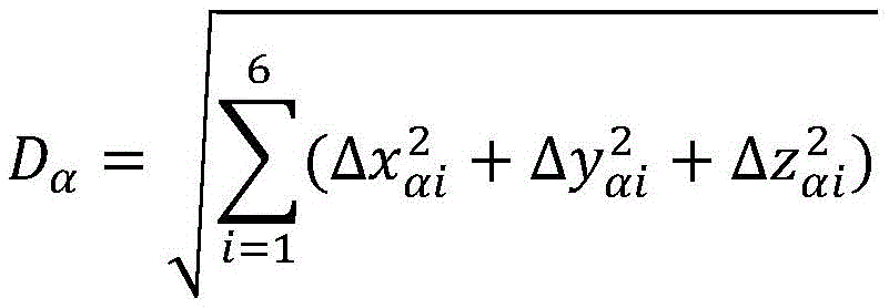
S6: according to Δ xi、Δyi、ΔziDefining the integrated nominal distance of the control points:

values of alpha, beta and gamma are obtained which correspond to the minimum of the combined nominal distance D of the control points.
On the basis of the technical scheme, the comprehensive nominal distance D of the control points is minimized, and the values of alpha, beta and the bending degree of freedom gamma are respectively calculated, and the method specifically comprises the following steps:
only considering alpha, carrying out sensitivity analysis to minimize the comprehensive nominal distance of the control point and obtain the value of alpha;
substituting the value of alpha to carry out sensitivity analysis, so that the comprehensive nominal distance of the control point is minimum, and a value of beta is obtained;
substituting the values of alpha and beta to carry out sensitivity analysis, so that the comprehensive nominal distance of the control points is minimum, and the value of the bending degree of freedom gamma is obtained.
On the basis of the technical scheme, the coordinate increment generated by alpha, beta and gamma specifically comprises the following steps:
α yields the respective control point coordinate increments as:
dyαi=|yi|·(1-cosα)
dzαi=|yi|·tanα
dxαi=0
β yields control point coordinate increments of:
dxβi=|xi|·(1-cosβ)
dzβi=|xi|·tanβ
dyβi=0
the coordinate increment of the control point generated by the bending degree of freedom gamma is as follows:
dxγi=ri·(1-cosγ)
dyγi=ri·sinγ
dzβi=0
riis the distance of the control point to the centroid.
On the basis of the technical scheme, the coordinate difference delta x of the ith control point after the linear centroids are alignedi、Δyi、ΔziComprises the following steps:
Δxi=0+|xi|·(1-cosβ)+ri·(1-cosγ)+dx
Δyi=|yi|·(1-cosα)+0+ri·sinγ+dy
Δzi=|yi|·tanα+|xi|·tanβ+0+dz
on the basis of the technical scheme, sensitivity analysis is carried out by only considering alpha, so that the comprehensive nominal distance of the control points is minimum, and the value of the alpha is obtained, and the method specifically comprises the following steps:


and carrying out sensitivity analysis on alpha to minimize the comprehensive nominal distance of the control points so as to obtain the value of alpha. On the basis of the technical proposal, the device comprises a shell,
on the basis of the technical scheme, sensitivity analysis is performed on alpha, so that the comprehensive nominal distance of the control points is minimum, and the value of the alpha is obtained, and the method specifically comprises the following steps:
according to the actual application of the engineering, two alpha values in the engineering application range are taken to obtain(α1,D1)、(α2,D2) Can fit a straight line, take alpha1、α2The opposite number of (c) to obtain (-alpha)1,D1)、(-α2,D2) Another straight line can be fitted, and the intersection point of the two straight lines is (alpha)i1,Di1),αi1I.e. alpha.
Compared with the prior art, the invention has the advantages that: the linear centroids of the control points measured twice are taken as the coordinate difference of the reference translation, 3 translation freedom solutions are directly obtained, then the 3 rotation freedom solutions are integrally solved by iteration, the convergence speed is high, alpha, beta and gamma can be quickly solved, the calculation time can be saved, the construction efficiency is improved, and the parameters can guide the matching connection between two adjacent segments.
Drawings
FIG. 1 is a schematic diagram of the positions of various control points in an embodiment of the present invention;
FIG. 2 is a schematic diagram of α solution in an embodiment of the present invention;
FIG. 3 is a schematic diagram of a control point line formed by control points according to an embodiment of the present invention;
fig. 4 is a schematic diagram of iterative solution results of α, β, and γ in an embodiment of the present invention.
Detailed Description
The present invention will be described in further detail with reference to the accompanying drawings and examples.
The embodiment of the invention provides a bridge segment short-line method prefabrication matching connection method, which comprises the following steps:
s1: establishing a coordinate system at the middle point of a fixed end mould of a pouring section, arranging a plurality of control points at preset positions, sequentially connecting the control points to form a control point line shape, measuring the coordinates of the control points for the first time after the maintenance of the pouring section is finished, and calculating to obtain the centroid coordinates of the control point line shape formed by the control points for the first time. As shown in fig. 1, in the present embodiment, the control points of a segment are symmetrical about the central axis of the segment. As shown in fig. 3, the control point line shape is a line shape in which the control points are connected in the order in the engineering application.
Specifically, a starting section is poured, the pouring section is poured by taking the starting section as a matched beam, a plurality of control points are arranged at preset positions of the pouring section, and the linear centroid of the control points is calculated according to the coordinates of the control points measured for the first time. Ready for subsequent translation.
S2: and taking the casting section as a matched beam of the next casting section, measuring coordinates of each control point of the casting section serving as the matched beam for the second time after the maintenance of the next casting section is finished, and calculating to obtain the linear centroid coordinates of the control points formed by each control point measured for the second time.
Specifically, after the maintenance of the initial segment is completed, the initial segment is hoisted to a storage area. And taking the cured casting section as a matched beam of the next casting section, and measuring the coordinates of each control point of the casting section serving as the matched beam for the second time after the curing of the next casting section is finished to obtain the linear centroid of each control point measured for the second time. And when the coordinates of each control point of the casting section serving as the matched beam are measured for the second time, the coordinates of each control point of the next casting section are measured for the first time, and preparation is made for obtaining the matching parameters when the casting section serving as the matched beam is cast for the next casting section.
S3: the difference between the two centroid coordinates is calculated to solve for the 3 translational degrees of freedom dx, dy, dz. Specifically, 3 translational degrees of freedom dx, dy, and dz are obtained from the centroid coordinate difference of the line formed by measuring each control point twice.
In this embodiment, dx is a coordinate difference in the x direction, dy is a coordinate difference in the y direction, and dz is a coordinate difference in the z direction.
S4: the 3 rotational degrees of freedom defining sequential rotations along the x, y and z axes of the poured segment as a matched beam are respectively: alpha, beta and a mean bending degree of freedom gamma, and coordinate increments generated by the alpha, beta and gamma are calculated. In this embodiment, α is a rotational degree of freedom along the x-axis of the cast section as the mating beam, β is a rotational degree of freedom along the y-axis of the cast section as the mating beam, and γ is a rotational degree of freedom along the z-axis of the cast section as the mating beam.
S5: from alpha, beta and gammaAnd 3 translational degrees of freedom dx, dy and dz, and calculating the coordinate difference delta x of the ith control point after the linear centroids of the control points are alignedi、Δyi、Δzi。
Preferably, α produces respective control point coordinate increments of:
dyαi=|yi|·(1-cosα)
dzαi=|yi|·tanα
dxαi=0
β yields control point coordinate increments of:
dxβi=|xi|·(1-cosβ)
dzβi=|xi|·tanβ
dyβi=0
the coordinate increment of the control point generated by the bending degree of freedom gamma is as follows:
dxγi=ri·(1-cosγ)
dyγi=ri·sinγ
dzγi=0
riis the distance of the control point to the centroid.
Calculating the delta x according to the coordinate increment generated by alpha, beta and gamma and the 3 translation freedom degrees dx, dy and dzi、Δyi、Δzi,
Δxi=0+|xi|·(1-cosβ)+ri·(1-cosγ)+dx
Δyi=|yi|·(1-cosα)+0+ri·sinγ+dy
Δzi=|yi|·tanα+|xi|·tanβ+0+dz
S6: according to Δ xi、Δyi、ΔziDefining the integrated nominal distance of the control points:

values of alpha, beta and gamma are obtained which correspond to the minimum of the combined nominal distance D of the control points.
Preferably, the method for minimizing the combined nominal distance D of the control points and determining the values of α, β and the translational degree of freedom γ respectively comprises:
sensitivity analysis was performed considering only α, minimizing the integrated nominal distance of the control points, resulting in a value of α. Specifically, the method comprises the following steps:

because DαIs a concave function, so DαThere are minimum values, and the procedure is specifically demonstrated as follows.
Control point y at the central axis i0, all control points approximately symmetrical about the central axisiSubstantially equal is set to y, then:

since α is a tiny amount, tan α ≈ sin α, which is simplified as:

taking the first term of Taylor expansion of its sine function as:
Dα≈2|y|·|α|
so that the distance DαIs a concave function of alpha, and sensitivity analysis is carried out on alpha to ensure that the comprehensive nominal distance of the control points is minimum to obtain the value of alpha.
Sensitivity analysis is carried out on alpha, as shown in figure 2, according to the practical application of engineering, two alpha values in the engineering application range are taken, and then (alpha) can be obtained1,D1)、(α2,D2) Can fit a straight line, take alpha1、α2The opposite number of (c) to obtain (-alpha)1,D11)、(-α2,D22) Another straight line can be fitted, and the intersection point of the two straight lines is (alpha)i1,Di1),αi1I.e. alpha.
In other embodiments, may be at αi1Within a set interval, take one more alpha3Obtaining (alpha)3,D3) And (α)i1,Di1) Combining to fit a straight line, taking alphai1、α3The opposite number of (c) to obtain (-alpha)i1,Di1)、(-α3,D33) Another straight line can be fitted, and the intersection point of the two straight lines is (alpha)i2,Di2),αi2I.e. alpha.
As shown in fig. 4, the exact solution of α can be found through two iterations of multiple verification calculations, and this method can save the time for finding α. Of course, in other embodiments, more iterations may be performed to obtain a more accurate result.
And substituting the value of alpha to carry out sensitivity analysis, wherein the adopted method is consistent with the method of alpha, so that the comprehensive nominal distance of the control points is minimum, and the value of beta is obtained.
Likewise, considering only β, one can obtain:


control point x at the central axis i0, all control points x approximately symmetrical about the central axisiSubstantially equal is set to x, then:

since β is a minor amount, tan β ≈ sin β, which is simplified as:

taking the first term of Taylor expansion of its sine function as:
Dβ≈2|x|·|β|
distance DβIs a concave function of beta, distance DβThere is also a minimum value.
Substituting the values of alpha and beta to carry out sensitivity analysis, and leading the comprehensive nominal distance of the control point to be minimum and the value of the bending degree of freedom gamma to be flat by adopting a method consistent with the method of alpha.
Likewise, the distance D can be obtained by considering only the degree of freedom γ of the flat bendingγIs a concave function of gamma. Substituting the values of alpha and beta, so performing sensitivity analysis, wherein the adopted method is consistent with the method of alpha, the comprehensive nominal distance of the control point is minimum, and the value of the bending degree of freedom gamma is obtained.
In summary, the coordinate difference of the control point linear centroid measured twice as the reference translation is directly obtained to obtain 3 translation freedom solutions, and then the 3 rotation freedom solutions are integrally solved by iteration, so that the convergence speed is high, alpha, beta and gamma can be rapidly solved, the calculation time can be saved, the construction efficiency can be improved, and the parameters can guide the matching and the connection between two adjacent sections.
The present invention is not limited to the above-described embodiments, and it will be apparent to those skilled in the art that various modifications and improvements can be made without departing from the principle of the present invention, and such modifications and improvements are also considered to be within the scope of the present invention. Those not described in detail in this specification are within the skill of the art.
Claims (6)
1. A bridge segment short-line method prefabrication matching connection method is characterized by comprising the following steps:
s1: establishing a coordinate system at the middle point of a fixed end mould of a pouring section, arranging a plurality of control points at preset positions, sequentially connecting the control points to form a control point line shape, measuring the coordinates of the control points for the first time after the maintenance of the pouring section is finished, and calculating to obtain the centroid coordinates of the control point line shape formed by the control points for the first time;
s2: taking the casting section as a matched beam of the next casting section, measuring coordinates of each control point of the casting section serving as the matched beam for the second time after the maintenance of the next casting section is finished, and calculating to obtain the linear centroid coordinates of the control points formed by each control point measured for the second time;
s3: calculating the difference value of the coordinates of the two centroids to obtain 3 translation degrees of freedom dx, dy and dz;
s4: the 3 rotational degrees of freedom defining sequential rotations along the x, y and z axes of the poured segment as a matched beam are respectively: alpha, beta and gamma, and calculating coordinate increment generated by the alpha, the beta and the gamma;
s5: according to the coordinate increment generated by alpha, beta and gamma and 3 translation degrees of freedom dx, dy and dz, the coordinate difference delta x of the ith control point after the linear centroids of the control points are aligned is solvedi、Δyi、Δzi;
S6: according to Δ xi、Δyi、ΔziDefining the integrated nominal distance of the control points:

values of alpha, beta and gamma are obtained which correspond to the minimum of the combined nominal distance D of the control points.
2. The bridge segment stub method prefabrication matching engagement method of claim 1, wherein obtaining corresponding values of α, β and γ when the combined nominal distance D of the control points is minimized specifically includes:
only considering alpha, carrying out sensitivity analysis to minimize the comprehensive nominal distance of the control point and obtain the value of alpha;
substituting the value of alpha to carry out sensitivity analysis, so that the comprehensive nominal distance of the control point is minimum, and a value of beta is obtained;
substituting the values of alpha and beta to carry out sensitivity analysis, so that the comprehensive nominal distance of the control points is minimum, and the value of the bending degree of freedom gamma is obtained.
3. The bridge segment stub method prefabricated mating connection method of claim 1, wherein the coordinate increments generated by α, β and γ specifically include:
α yields the respective control point coordinate increments as:
dyαi=|yi|·(1-cosα)
dzαi=|yi|·tanα
dxαi=0
β yields control point coordinate increments of:
dxβ=|xi|·(1-cosβ)
dzβ=|xi|·tanβ
dyβ=0
the coordinate increment of the control point generated by the bending degree of freedom gamma is as follows:
dxγ=ri·(1-cosγ)
dyγ=ri·sinγ
dzγ=0
riis the distance of the control point to the centroid.
4. The bridge segment stub method prefabrication matching and joining method of claim 3, wherein the coordinate difference Δ x after alignment of the line centroids of the ith control pointi、Δyi、ΔziComprises the following steps:
Δxi=0+|xi|·(1-cosβ)+ri·(1-cosγ)+dx
Δyi=|yi|·(1-cosα)+0+ri·sinγ+dy
Δzi=|yi|·tanα+|xi|·tanβ+0+dz
5. the bridge segment stub method prefabricated mating joining method of claim 4, wherein: and only considering alpha, carrying out sensitivity analysis to minimize the comprehensive nominal distance of the control points to obtain a value of alpha, wherein the method specifically comprises the following steps:


and carrying out sensitivity analysis on alpha to minimize the comprehensive nominal distance of the control points so as to obtain the value of alpha.
6. The bridge segment stub method prefabricated mating joining method of claim 5, wherein: and carrying out sensitivity analysis on alpha to minimize the comprehensive nominal distance of the control points to obtain a value of alpha, wherein the sensitivity analysis specifically comprises the following steps:
according to the actual application of the engineering, two alpha values in the engineering application range are taken to obtain (alpha)1,D1)、(α2,D2) Can fit a straight line, take alpha1、α2The opposite number of (c) to obtain (-alpha)1,D1)、(-α2,D2) Another straight line can be fitted, and the intersection point of the two straight lines is (alpha)i1,Di1),αi1I.e. alpha.
Priority Applications (1)
| Application Number | Priority Date | Filing Date | Title |
|---|---|---|---|
| CN201910625628.3A CN110374005B (en) | 2019-07-11 | 2019-07-11 | Bridge segment short-line method prefabrication matching connection method |
Applications Claiming Priority (1)
| Application Number | Priority Date | Filing Date | Title |
|---|---|---|---|
| CN201910625628.3A CN110374005B (en) | 2019-07-11 | 2019-07-11 | Bridge segment short-line method prefabrication matching connection method |
Publications (2)
| Publication Number | Publication Date |
|---|---|
| CN110374005A CN110374005A (en) | 2019-10-25 |
| CN110374005B true CN110374005B (en) | 2021-03-16 |
Family
ID=68252792
Family Applications (1)
| Application Number | Title | Priority Date | Filing Date |
|---|---|---|---|
| CN201910625628.3A Active CN110374005B (en) | 2019-07-11 | 2019-07-11 | Bridge segment short-line method prefabrication matching connection method |
Country Status (1)
| Country | Link |
|---|---|
| CN (1) | CN110374005B (en) |
Families Citing this family (3)
| Publication number | Priority date | Publication date | Assignee | Title |
|---|---|---|---|---|
| CN110777669A (en) * | 2019-11-15 | 2020-02-11 | 中铁北京工程局集团有限公司 | High-speed rail continuous beam short line matching prefabricated cantilever assembly line shape control method |
| CN111622114B (en) * | 2020-05-08 | 2021-08-10 | 中铁大桥科学研究院有限公司 | Bridge segment prefabrication construction line shape error adjusting method |
| CN112192741B (en) * | 2020-09-09 | 2022-04-01 | 瀚阳国际工程咨询有限公司 | Numerical control method for measuring accuracy analysis of segmental precast bridge |
Citations (7)
| Publication number | Priority date | Publication date | Assignee | Title |
|---|---|---|---|---|
| JPH08142034A (en) * | 1994-11-24 | 1996-06-04 | Kumagai Gumi Co Ltd | Automatic control device of form for short line match casting |
| JP2000290933A (en) * | 1999-04-07 | 2000-10-17 | Yokogawa Bridge Corp | Method for controlling form of precast segment, and method for erecting bridge by precast segment construction method |
| CN101942805A (en) * | 2010-09-17 | 2011-01-12 | 广州瀚阳工程咨询有限公司 | Three-dimensional numerical control method for bridge section precasting technology |
| CN102733311A (en) * | 2012-07-02 | 2012-10-17 | 中铁大桥局集团武汉桥梁科学研究院有限公司 | Line shape control method for short line method segment prefabrication construction |
| CN106223201A (en) * | 2016-07-26 | 2016-12-14 | 中南大学 | The method for correcting error of beam section bridge linear monitoring |
| CN208421548U (en) * | 2018-08-12 | 2019-01-22 | 广州瀚阳工程咨询有限公司 | A kind of automatic control system applied to short-line prefabrication bridge subsection |
| CN109543216A (en) * | 2018-10-16 | 2019-03-29 | 华南理工大学 | A kind of segment girder precast linear control method based on slug matching |
Family Cites Families (2)
| Publication number | Priority date | Publication date | Assignee | Title |
|---|---|---|---|---|
| CN101028726A (en) * | 2006-09-21 | 2007-09-05 | 中铁大桥局股份有限公司 | Precast PC case beam process by short-line method |
| CN108731598B (en) * | 2018-05-22 | 2022-10-25 | 上海贝英吉工程咨询有限公司 | Matched beam section positioning method based on distance control |
-
2019
- 2019-07-11 CN CN201910625628.3A patent/CN110374005B/en active Active
Patent Citations (7)
| Publication number | Priority date | Publication date | Assignee | Title |
|---|---|---|---|---|
| JPH08142034A (en) * | 1994-11-24 | 1996-06-04 | Kumagai Gumi Co Ltd | Automatic control device of form for short line match casting |
| JP2000290933A (en) * | 1999-04-07 | 2000-10-17 | Yokogawa Bridge Corp | Method for controlling form of precast segment, and method for erecting bridge by precast segment construction method |
| CN101942805A (en) * | 2010-09-17 | 2011-01-12 | 广州瀚阳工程咨询有限公司 | Three-dimensional numerical control method for bridge section precasting technology |
| CN102733311A (en) * | 2012-07-02 | 2012-10-17 | 中铁大桥局集团武汉桥梁科学研究院有限公司 | Line shape control method for short line method segment prefabrication construction |
| CN106223201A (en) * | 2016-07-26 | 2016-12-14 | 中南大学 | The method for correcting error of beam section bridge linear monitoring |
| CN208421548U (en) * | 2018-08-12 | 2019-01-22 | 广州瀚阳工程咨询有限公司 | A kind of automatic control system applied to short-line prefabrication bridge subsection |
| CN109543216A (en) * | 2018-10-16 | 2019-03-29 | 华南理工大学 | A kind of segment girder precast linear control method based on slug matching |
Non-Patent Citations (8)
| Title |
|---|
| 《基于斜率最小二乘法的短线预制修正》;詹朝敬;《低温建筑技术》;20111130;第57-59页 * |
| 《基于连续梁桥短线法施工控制的结构参数敏感性分析》;黄跃;《中国港湾建设》;20110430;第10-12页 * |
| 《基于非线性最小二乘的短线法节段预制线形控制研究》;侍刚;《世界桥梁》;20141231;第36-40页 * |
| 《大型短线拼装桥梁的施工监控及损伤预后研究》;司旭龙;《中国优秀硕士学位论文全文数据库工程科技Ⅱ辑》;20180228;全文 * |
| 《大曲率短线匹配连续刚构桥空间几何线形控制》;罗锦;《铁道科学与工程学报》;20180731;第1738-1746页 * |
| 《节段式混凝土桥梁预制阶段线形与姿态控制系统》;王侃;《中国优秀硕士学位论文全文数据库工程科技Ⅱ辑》;20080831;全文 * |
| 《节段箱梁预制拼装连续梁体系关键技术研究》;朱新安;《中国优秀硕士学位论文全文数据库工程科技Ⅱ辑》;20150731;全文 * |
| 《连续梁桥短线预制阶段施工线形控制系统研究》;陈前融;《中国优秀硕士学位论文全文数据库工程科技Ⅱ辑》;20190228;全文 * |
Also Published As
| Publication number | Publication date |
|---|---|
| CN110374005A (en) | 2019-10-25 |
Similar Documents
| Publication | Publication Date | Title |
|---|---|---|
| CN110374005B (en) | Bridge segment short-line method prefabrication matching connection method | |
| CN109543216B (en) | Segment beam prefabricated line shape control method based on stub matching method | |
| CN106223201B (en) | The method for correcting error of beam section bridge linear monitoring | |
| CN102733311B (en) | Line shape control method for short line method segment prefabrication construction | |
| US9435633B2 (en) | Quasi-virtual locate/drill/shim process | |
| CN106903663B (en) | A kind of positioning and marking method, the apparatus and system of the built-in part of revolving shell | |
| CN111622114B (en) | Bridge segment prefabrication construction line shape error adjusting method | |
| JP2000290933A (en) | Method for controlling form of precast segment, and method for erecting bridge by precast segment construction method | |
| CN109184819B (en) | Method for measuring radial through-flow gap of steam turbine by laser tracking measurement system | |
| CN110411338B (en) | Welding gun tool parameter three-dimensional scanning calibration method for robot arc additive repair | |
| CN109469333B (en) | Multi-angle multi-bracket complex node inclined hanging column accurate positioning method | |
| CN115659479B (en) | Bridge short-line method prefabricated construction beam section matching method | |
| CN104775612A (en) | Three-dimensional distorted rotating inclined reinforced concrete frame structure template and construction method thereof | |
| US20150096707A1 (en) | Method for positioning and fixing mold parts in casting molds | |
| CN115075296A (en) | Calibration method for curve section pipe joint | |
| CN114232506B (en) | Construction method for main arch rib of steel box girder tie bar steel arch bridge | |
| CN108762059A (en) | A kind of automatic control system applied to short-line prefabrication bridge subsection | |
| CN115923181A (en) | Method and system for measuring winding track precision of composite material shell | |
| CN208421548U (en) | A kind of automatic control system applied to short-line prefabrication bridge subsection | |
| CN116579046A (en) | Steel structure pre-assembling method with center registration and joint self-holding device | |
| CN108120430B (en) | Paying-off method for gate mounting hole in nuclear island containment vessel | |
| JP3165339B2 (en) | Automatic formwork control system for short line match casting | |
| CN112726407B (en) | Prefabricated line shape control method matched with prefabricated bridge deck and storage medium | |
| CN109243626A (en) | ACP1000 nuclear pressure container cylinder insulating layer installation method | |
| CN107170494A (en) | The groove measurement processing method of main pipeline in AP1000 nuclear power stations |
Legal Events
| Date | Code | Title | Description |
|---|---|---|---|
| PB01 | Publication | ||
| PB01 | Publication | ||
| SE01 | Entry into force of request for substantive examination | ||
| SE01 | Entry into force of request for substantive examination | ||
| GR01 | Patent grant | ||
| GR01 | Patent grant |