CN110306552B - Method for breaking hard underwater layer - Google Patents
Method for breaking hard underwater layer Download PDFInfo
- Publication number
- CN110306552B CN110306552B CN201910360208.7A CN201910360208A CN110306552B CN 110306552 B CN110306552 B CN 110306552B CN 201910360208 A CN201910360208 A CN 201910360208A CN 110306552 B CN110306552 B CN 110306552B
- Authority
- CN
- China
- Prior art keywords
- pile
- steel pipe
- hard layer
- steel
- pipe piles
- Prior art date
- Legal status (The legal status is an assumption and is not a legal conclusion. Google has not performed a legal analysis and makes no representation as to the accuracy of the status listed.)
- Active
Links
- 238000000034 method Methods 0.000 title claims abstract description 19
- 229910000831 Steel Inorganic materials 0.000 claims abstract description 70
- 239000010959 steel Substances 0.000 claims abstract description 70
- 238000005553 drilling Methods 0.000 claims abstract description 16
- 238000010276 construction Methods 0.000 claims abstract description 13
- XLYOFNOQVPJJNP-UHFFFAOYSA-N water Substances O XLYOFNOQVPJJNP-UHFFFAOYSA-N 0.000 claims abstract description 10
- 238000003466 welding Methods 0.000 claims abstract description 10
- 230000000149 penetrating effect Effects 0.000 claims abstract description 4
- 238000009527 percussion Methods 0.000 claims abstract description 3
- 230000035515 penetration Effects 0.000 claims description 5
- 238000013467 fragmentation Methods 0.000 claims description 2
- 238000006062 fragmentation reaction Methods 0.000 claims description 2
- 238000005516 engineering process Methods 0.000 description 5
- 238000005422 blasting Methods 0.000 description 2
- 241000287509 Piciformes Species 0.000 description 1
- 230000009286 beneficial effect Effects 0.000 description 1
- 238000001514 detection method Methods 0.000 description 1
- 230000000694 effects Effects 0.000 description 1
Images


Classifications
-
- E—FIXED CONSTRUCTIONS
- E02—HYDRAULIC ENGINEERING; FOUNDATIONS; SOIL SHIFTING
- E02D—FOUNDATIONS; EXCAVATIONS; EMBANKMENTS; UNDERGROUND OR UNDERWATER STRUCTURES
- E02D7/00—Methods or apparatus for placing sheet pile bulkheads, piles, mouldpipes, or other moulds
- E02D7/18—Placing by vibrating
-
- E—FIXED CONSTRUCTIONS
- E21—EARTH OR ROCK DRILLING; MINING
- E21B—EARTH OR ROCK DRILLING; OBTAINING OIL, GAS, WATER, SOLUBLE OR MELTABLE MATERIALS OR A SLURRY OF MINERALS FROM WELLS
- E21B1/00—Percussion drilling
Landscapes
- Engineering & Computer Science (AREA)
- Mining & Mineral Resources (AREA)
- Life Sciences & Earth Sciences (AREA)
- Geology (AREA)
- General Life Sciences & Earth Sciences (AREA)
- Paleontology (AREA)
- General Engineering & Computer Science (AREA)
- Structural Engineering (AREA)
- Mechanical Engineering (AREA)
- Physics & Mathematics (AREA)
- Environmental & Geological Engineering (AREA)
- Fluid Mechanics (AREA)
- Civil Engineering (AREA)
- Geochemistry & Mineralogy (AREA)
- Earth Drilling (AREA)
- Piles And Underground Anchors (AREA)
- Placing Or Removing Of Piles Or Sheet Piles, Or Accessories Thereof (AREA)
Abstract
The invention belongs to the technical field of underwater hard layer crushing, and particularly relates to a method for crushing an underwater hard layer, which comprises the following steps: s1, taking three pile positions, and drilling pile position holes in the three pile positions by using a geological drilling machine; s2, penetrating the three steel pipe piles into three pile position holes in the hard layer by adopting a vibration hammer, welding a hanger at the position, 1.5m away from the water surface, of the middle steel pipe pile, and mounting a pulley on the hanger; s3, releasing three steel pipe pile position sub-points for the carrying pole beam; then, lugs are welded at other points of the carrying pole beam where the steel pipe piles need to be driven, and pulleys are installed on the lugs; s4, erecting the shoulder pole beam on the three steel pipe piles; s5, hoisting the percussion drill to the specified position of the steel trestle bridge floor system, and performing reinforced connection with the steel trestle bridge floor system; s6, releasing the steel wire rope by the impact drilling machine, and connecting the steel wire rope with a 6t heavy hammer; and S7, starting to hammer the hard layer by the hammer drill to carry out crushing construction. The invention can safely and effectively crush the underwater hard layer, thereby enabling the steel pipe pile to smoothly penetrate.
Description
Technical Field
The invention belongs to the technical field of underwater hard layer crushing, and particularly relates to a method for crushing an underwater hard layer.
Background
Along the development of cities, construction planes are narrower and narrower, so that more and more urban viaducts and bridges need to be constructed on water. The steel trestle is as the construction way commonly used of operation on water, and the steel-pipe pile basis is adopted in general design, and DZA series vibratory hammer carries out the bridge construction on water. Taking model DZ90A as an example, the specific parameters are as follows: the vibration exciting force is 0-579 KN, the no-load amplitude is 0-6.6 mm, the mass of the hammer body is 6200kg, the power of the motor is 90KW, and the rotating speed is 0-960 r/min. When a DZA series vibration hammer is used for driving a steel pipe pile and a hard layer is arranged on the bottom of a canal or a river, the steel pipe pile is difficult to penetrate into a geological layer. The hard layer is broken by underwater cutting, blasting, steel cofferdam and other modes by divers, the cost is overhigh, the safety is low, and the construction period is longer.
Disclosure of Invention
In view of the above technical problems, an object of the present invention is to provide a method for breaking an underwater hard layer, which can safely and effectively break the underwater hard layer, so that a steel pipe pile can be smoothly inserted.
In order to achieve the purpose, the technical scheme adopted by the invention is as follows:
a method of underwater hard layer fragmentation characterized by the steps of:
s1, taking three pile positions transversely arranged along the steel trestle bridge floor system in a water area at the front end of the steel trestle bridge floor system, and drilling pile position holes on underwater hard layers corresponding to the three pile positions by using a geological drilling machine;
s2, penetrating the three steel pipe piles into the three pile position holes in the hard layer by adopting a vibration hammer, leveling the three steel pipe piles after the steel pipe piles reach the required penetration degree, and welding pile caps; welding a hanger at the position of 1.5m of the middle steel pipe pile exposed out of the water surface, and mounting a pulley on the hanger;
s3, measuring the carrying pole beam and releasing three steel pipe pile position sub-points; then, lugs are welded at other points of the carrying pole beam where the steel pipe piles need to be driven, and pulleys are installed on the lugs;
s4, erecting the shoulder pole beam on the three steel pipe piles, and firmly welding;
s5, hoisting the percussion drill to the specified position of the steel trestle bridge floor system, and performing reinforced connection with the steel trestle bridge floor system;
s6, releasing the steel wire rope by the impact drilling machine, sequentially passing through the pulleys 4 in the steps S2 and S3, and connecting the pulleys with a 6t heavy hammer;
and S7, tightening the steel wire rope by the impact drilling machine, and starting to apply and beat a hard layer to perform crushing construction.
Further, in the step S1, nine holes are drilled in the pile position circumferential direction by using a drill bit with a diameter of 220mm for each pile position hole.
Furthermore, two sides of the steel trestle bridge deck system 2 are respectively provided with a Bailey beam used as an operating platform.
The invention has the beneficial effects that:
(1) the method adopts common engineering equipment and processes for combination to form a new technology for crushing the underwater hard layer, and compared with the conventional common schemes (blasting, underwater woodpeckers and the like) for underwater crushing, the technology can reduce the construction time and greatly reduce the mechanical and labor costs.
(2) The technology has the advantages of simple and easy-to-use equipment, strong operability, remarkable crushing effect and suitability for most of underwater strata.
(3) The technology can be operated on shore by utilizing equipment, underwater operation is not needed, and compared with the common scheme of underwater crushing, the technology has the advantages of higher safety and greatly reduced mechanical and labor costs.
Drawings
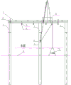
FIG. 1 is a schematic side view of the construction process of the present method in the embodiment.
FIG. 2 is a schematic front view of the construction process of the present method in the embodiment.
FIG. 3 is a schematic top view of the embodiment in which the method is used in construction.
In the figure: 1-steel pipe pile, 2-steel trestle bridge deck system, 3-shoulder pole beam, 4-pulley, 5-lifting lug, 6-impact drilling machine, 7-heavy hammer, 8-Bailey beam and 9-hard layer.
Detailed Description
For a better understanding of the present invention, the technical solutions of the present invention will be further described below with reference to the following examples and accompanying drawings.
As shown in fig. 1, 2 and 3, a method for breaking an underwater hard layer comprises the following steps:
s1, taking three pile positions (the three pile positions comprise two ends and a middle position) transversely arranged along the steel trestle bridge floor system 2 at the front end water area of the steel trestle bridge floor system 2, and drilling pile position holes (9 holes are drilled by a drill bit with the diameter of 220 mm) on an underwater hard layer corresponding to the three pile positions by using a geological drilling machine;
s2, penetrating the three steel pipe piles 1 into three pile position holes in the hard layer by adopting a DZ90A vibration hammer 7, leveling the three steel pipe piles 1 after the steel pipe piles 1 reach the required penetration degree, and welding pile caps; welding a lifting lug 5 at a position 1.5m above the water surface of the middle steel pipe pile 1, and mounting a pulley 4 on the lifting lug 5 (using a 50t crawler crane to lift the pulley 4 to the lifting lug 5 and connecting the pulley with a lifting ring);
s3, measuring the carrying pole beam 3, and releasing 1-position sub-points of the three steel pipe piles; then, a lifting lug 5 is welded at a point of the carrying pole beam 3 where the steel pipe pile 1 (except the three steel pipe piles 1) is required to be driven, and a pulley 4 is installed on the lifting lug 5 (the pulley 4 is lifted to the corresponding lifting lug 5 below the carrying pole beam 3 by a 50t crawler crane and connected by a lifting ring);
s4, erecting the carrying pole beam 3 on the three steel pipe piles 1, and firmly welding;
s5, hoisting the impact drilling machine 6 to the specified position of the steel trestle bridge floor system 2 by using a 50t crawler crane, and performing reinforced connection with the steel trestle bridge floor system 2; two sides of the steel trestle bridge floor system 2 are respectively provided with a Bailey beam 8 used as an operating platform;
s6, releasing a steel wire rope by a hammer drill 6, sequentially passing through the pulley 4 (model HQGK1-20 t) in the steps S2 and S3, and connecting with a 6t heavy hammer 7;
s7, the impact drill 6 tightens the steel wire rope (after the steel wire rope is stressed, safety and stability detection is carried out), and crushing construction is carried out on the hard layer 9 (the impact drill 6 is used for driving in the same process as the common impact drill 6, the penetration depth of the heavy hammer 7 is controlled according to the thickness of the hard layer 9, and the penetration depth is generally 500 mm-1000 mm).
And in the step S1, nine holes are drilled in the pile position circumferential direction by adopting a drill bit with the diameter of 220mm for each pile position hole.
S8, after the hard layer 9 is broken, the steel trestle bridge deck system 2 enters a general construction procedure, and the geological drilling rig drills a next row of pile positions in advance. And repeating the steps when the steel trestle bridge deck system 2 is constructed to the next row of steel pipe piles.
The steel pipe pile 1, phi 630 and the pile foundation part of the steel trestle also play a role of a support of the shoulder pole beam.
The shoulder pole beam 3 is H-shaped steel (HW 600x300 b) and transmits the force of the pulley 4 to the steel pipe pile 1.
The pulley 4 (HQGK 1-20 t) is used for guiding the steel wire rope;
the lifting lugs 5 are used for connecting the pulleys 4 with the carrying pole beams 3 and the steel pipe piles 1;
the weight 7 weighs 6t and is used for smashing the hard layer 9 underwater.
The Bailey beam 8 is 321 type and is used for supporting a simple operating platform.
The above description is only an application example of the present invention, and certainly, the present invention should not be limited by this application, and therefore, the present invention is still within the protection scope of the present invention by equivalent changes made in the claims of the present invention.
Claims (3)
1. A method of underwater hard layer fragmentation characterized by the steps of:
s1, taking three pile positions transversely arranged along the steel trestle bridge floor system (2) in the front water area of the steel trestle bridge floor system (2), and drilling pile position holes on the underwater hard layer corresponding to the three pile positions by using a geological drilling machine;
s2, penetrating the three steel pipe piles (1) into the three pile position holes in the hard layer by adopting a vibration hammer, leveling the three steel pipe piles (1) after the steel pipe piles (1) reach the required penetration degree, and welding pile caps; welding a lifting lug (5) at a position 1.5m above the water surface of a middle steel pipe pile (1), and mounting a pulley (4) on the lifting lug (5);
s3, measuring the carrying pole beam (3) and releasing the position points of the three steel pipe piles (1); then, lugs (5) are welded at the positions of the shoulder pole beam (3) where the steel pipe piles (1) are required to be driven, and pulleys (4) are installed on the lugs (5);
s4, erecting the carrying pole beam (3) on the three steel pipe piles (1) and firmly welding;
s5, hoisting the percussion drill (6) to the designated position of the steel trestle bridge floor system (2), and performing reinforced connection with the steel trestle bridge floor system (2);
s6, releasing the steel wire rope by the impact drilling machine (6), sequentially passing through the pulleys (4) in the steps S2 and S3, and then connecting with a 6t heavy hammer (7);
s7, the impact drilling machine (6) tightens the steel wire rope and starts to beat the hard layer (9) for crushing construction.
2. The method for underwater hard layer breaking according to claim 1, wherein each of the pile site holes in the step S1 is drilled nine holes along the circumference of the pile site by using a drill bit with a diameter of 220 mm.
3. A method for breaking up an underwater hard layer according to claim 1, characterized in that a bery beam (8) is provided on each side of the steel trestle deck system (2) as an operating platform.
Priority Applications (1)
| Application Number | Priority Date | Filing Date | Title |
|---|---|---|---|
| CN201910360208.7A CN110306552B (en) | 2019-04-30 | 2019-04-30 | Method for breaking hard underwater layer |
Applications Claiming Priority (1)
| Application Number | Priority Date | Filing Date | Title |
|---|---|---|---|
| CN201910360208.7A CN110306552B (en) | 2019-04-30 | 2019-04-30 | Method for breaking hard underwater layer |
Publications (2)
| Publication Number | Publication Date |
|---|---|
| CN110306552A CN110306552A (en) | 2019-10-08 |
| CN110306552B true CN110306552B (en) | 2021-01-19 |
Family
ID=68075378
Family Applications (1)
| Application Number | Title | Priority Date | Filing Date |
|---|---|---|---|
| CN201910360208.7A Active CN110306552B (en) | 2019-04-30 | 2019-04-30 | Method for breaking hard underwater layer |
Country Status (1)
| Country | Link |
|---|---|
| CN (1) | CN110306552B (en) |
Family Cites Families (3)
| Publication number | Priority date | Publication date | Assignee | Title |
|---|---|---|---|---|
| JPH10140565A (en) * | 1996-11-06 | 1998-05-26 | Kubota Corp | Embedding method of steel pipe pile and steel pipe pile used for it |
| CN203361116U (en) * | 2013-06-13 | 2013-12-25 | 中交路桥华南工程有限公司 | Drilling construction platform |
| CN105133506B (en) * | 2015-09-11 | 2016-09-14 | 中铁四局集团有限公司 | Construction method and facilities of steel trestle bridge with percussion drilling limit hole implantation combined with crawler crane |
-
2019
- 2019-04-30 CN CN201910360208.7A patent/CN110306552B/en active Active
Also Published As
| Publication number | Publication date |
|---|---|
| CN110306552A (en) | 2019-10-08 |
Similar Documents
| Publication | Publication Date | Title |
|---|---|---|
| CN101736755B (en) | Clean water hole pile foundation constructing method | |
| CN109797749B (en) | An underwater foundation pit construction device and construction method | |
| CN111236215A (en) | Rock-socketed construction process of large-diameter steel pipe inclined pile of offshore wind power high-rise pile cap foundation | |
| CN107034884A (en) | Construction device and method of steel casing with steep rock surface inclination in shallow overburden and deep water area | |
| CN115652927A (en) | Construction method of steel pipe pile sinking in deep water diversion hole | |
| CN119041476A (en) | Foundation construction method of offshore special-shaped root-opened rock-socketed jacket pile | |
| CN114370234A (en) | Bare rock riverbed steel pipe pile construction equipment and construction method | |
| CN217580865U (en) | Large-diameter steel casing drilling platform under deep water slope bare rock geological condition | |
| CN104805830A (en) | Uplift pile construction method without rock blasting | |
| CN110306552B (en) | Method for breaking hard underwater layer | |
| CN113417287B (en) | Construction method for removing underground secant pile by full-casing full-slewing drilling machine | |
| WO2022116916A1 (en) | Construction method for pulling out concrete pipe pile on water and pile pulling-out tool | |
| CN109989346B (en) | Bridge large-diameter precast concrete pipe column foundation and its construction method | |
| CN206859219U (en) | Steel casing construction device with large flow velocity and inclined rock face in deep water area of shallow overburden layer | |
| CN215367361U (en) | Open caisson pile clamping breaking structure | |
| CN113026688B (en) | System for expanding piles to form wall by using foundation rocks at bottom of concrete guide wall foundation | |
| CN217629873U (en) | Assembly for breaking existing prestressed anchor cable in pile foundation construction | |
| JP2000154538A (en) | Plumb bob type device for driving steel pipe in inner moat and plumb bob type construction method of driving steel pipe in inner moat | |
| CN115897581A (en) | A construction method for super-long and super-large-diameter locking steel pipe piles under complex geological conditions | |
| CN210163888U (en) | Quick construction structure of major diameter socketed pile | |
| JPH1030229A (en) | Steel pipe pressing-in method at narrow space portion with upper limitation | |
| CN218521809U (en) | Deep water high strength bare rock's fluting construction system | |
| JP2017190635A (en) | Construction method for steel pipe pile | |
| CN219732049U (en) | Construction structure of wading sand pebble stratum fore shaft steel pipe pile cofferdam | |
| CN220469840U (en) | Underwater blasting drilling drill pipe installation and disassembly auxiliary fixture |
Legal Events
| Date | Code | Title | Description |
|---|---|---|---|
| PB01 | Publication | ||
| PB01 | Publication | ||
| SE01 | Entry into force of request for substantive examination | ||
| SE01 | Entry into force of request for substantive examination | ||
| GR01 | Patent grant | ||
| GR01 | Patent grant |